1. Introduction
Maritime transportation is responsible for approximately 2.5% of global greenhouse gas (GHG) emissions, while projections indicate a significant increase, if mitigation measures are not properly and timely implemented [
1,
2,
3]. This rising concern about GHG emissions necessitates a shift towards sustainable shipping practices. In response, the International Maritime Organization (IMO) has established a target for international shipping to achieve net-zero greenhouse gas (GHG) emissions by 2050. It also establishes a commitment to promote the adoption of zero or near-zero GHG fuels by 2030, along with indicative emission reduction targets for the years 2030 and 2040.
Among various proposed solutions, Wind-Assisted Propulsion Systems (WAPS) have emerged as a promising alternative that leverages a free and abundant zero-emission energy source. Studies have demonstrated that WAPS can potentially reduce fuel consumption (and relevant CO
2 emissions) and the maritime industry is starting to adopt these technologies, with the number of commercial vessels currently utilizing WAPS steadily increasing. More specifically, the deployment of WAPS in commercial shipping has shown a clear upward trend in recent years. According to the European Maritime Safety Agency (EMSA), 30 vessels had WAPS installed by mid-2023 [
4]. More recent data from the International Windship Association (IWSA) indicate that by the end of the third quarter of 2024, approximately 45 vessels were equipped with WAPS, with at least 34 additional installations planned. In addition, ten vessels have been classified as “wind-ready,” nine of which were built between 2023 and 2024 [
5].
IWSA further reported in August 2024 that WAPS installations had tripled compared to the preceding 12-month period. This growth reflects increasing confidence in wind propulsion, driven by accumulating operational experience and the economic advantages it offers—particularly in the context of elevated fuel prices and the rising cost of low-emission alternatives.
While considerable progress has been made in studying the integration of WAPS into vessel designs [
6,
7,
8], current approaches mostly focus on retrofitting conventional ship designs with WAPS, rather than incorporating these systems into the initial design stages. There are studies that focus on the optimization of the number and placement of WAPS [
9], as well as the aerodynamic design characteristics of the WAPS themselves [
10] or optimization of energy efficiency of hybrid systems (e.g., sail, main engine and shaft generator) [
11]. However, limited attention has been given to the optimization of the vessel’s own design characteristics when equipped with wind-assisted propulsion systems.
Existing simulation and design tools have significantly advanced our knowledge about complex physical phenomena governing the operation of ships fitted with WAPS and their design [
10,
12,
13,
14,
15] and their viability as a potential investment [
16], though opportunities and gaps remain for further development in areas such as:
Expanding versatility for modeling multiple WAPS configurations and their arrangement
Enhancing economic assessment frameworks to better mode long-term value WAPS projects (business scenarios), while integrating the steadily evolving regulatory measures (Life Cycle Cost and Assessment, LCC and LCA).
Addressing the inherent complexity of multi-parameter, multi-objective and multi-constrained optimization in this domain
Thus, additional research and tool development is necessary to complement existing work and to support naval architects and marine engineers in the evolving field of WAPS integration.
This paper presents a versatile design optimization and assessment platform in line with previous works of the authors in the field [
17,
18], which will facilitate the holistic design of ships with WAPS [
19]. The platform integrates hydrodynamic, aerodynamic, economic, and regulatory considerations within a unified design software environment. Our approach enables the optimization across multiple objectives from the earliest conceptual design phases and an early assessment of the viability of WAPS projects. A key advantage of the presented platform over existing WAPS simulation and optimization tools lies in its capability to simultaneously optimize the vessel’s principal design characteristics—such as hull form, engine selection, and propeller parameters—while explicitly accounting for the influence of wind-assisted propulsion systems. One example of hull design optimization in the context of wind-assisted propulsion focuses on refining the hull form to improve resistance and propeller efficiency in wind-assisted vessels [
20]. However, this approach is tailored to later design stages and is not suitable for application during the conceptual design phase, where broader decisions regarding the vessel’s main particulars must be made.
The research presented in this paper contributes to ongoing efforts toward decarbonization in the maritime sector by providing a tool that helps bridge the gap between theoretical wind propulsion benefits and their practical implementation in commercial vessel design. The paper is structured as following: after a brief introduction,
Section 2 outlines the design philosophy behind the developed platform, followed by
Section 3, which presents the formulation of the integrated simulation and optimization framework.
Section 4 features a case study of a wind-assisted bulk carrier operating on a transpacific route between China and the USA, demonstrating the platform’s capabilities. The paper concludes with key findings, limitations and final remarks.
2. Design Philosophy of the Platform
To effectively serve the evolving needs of naval architects, ship owners, and operators interested in wind-assisted propulsion, the herein developed simulation and optimization platform is specifically designed with expandability and versatility being its primary features. This ensures adaptability to diverse operational scenarios, to different vessel types and sizes, to multiple wind propulsion technologies, and to a range of evaluation and optimization methods with adjustable levels of detail. The fundamental design requirements guiding the platform’s development include the key aspects elaborated in the following:
2.1. Adaptability to Different Routes and Environmental Conditions
The platform allows users to define customized vessel routes and combine them with historical or statistical weather data to simulate realistic operational conditions. Each route is divided into a discrete number of legs, with associated wind and wave parameters used to estimate the propulsion demand and fuel consumption. Environmental inputs are sourced from validated global weather datasets (e.g., ERA5), ensuring consistent and representative simulations.
To account for the variability in environmental conditions, the platform supports the simulation of multiple weather scenarios along the same route. This approach helps reduce uncertainty stemming from seasonal or year-to-year fluctuations, offering a more robust estimation of WAPS performance. Nevertheless, it should be noted that the energy savings predicted by the platform are likely conservative. Since fixed routes are assumed, the full benefit of wind-assisted propulsion is not fully captured. Maximum fuel savings can only be achieved through optimized weather routing, which dynamically adjusts the vessel’s course to exploit favorable wind conditions [
21].
2.2. Flexibility in WAPS Technology Integration
Recognizing the broad spectrum of available and emerging wind-assisted propulsion technologies, the platform is built to integrate alternative WAPS, whether passive (e.g., rigid wing sails, soft sails) or active (e.g., rotor sails, suction wings). To achieve this versatility, the platform requires minimal and standardized inputs for each WAPS type, including:
WAPS characteristics (dimensions, weights, center of mass, aerodynamic force application point etc.)
Aerodynamic performance data (lift and drag coefficients, operational limits, calculation of resulting forward thrust and side force)
Power consumption profiles as functions of wind characteristics (applicable to active WAPS)
This approach ensures a rapid adaptability to novel propulsion solutions as they emerge and allows users to efficiently evaluate different WAPS scenarios or configurations.
2.3. Versatile Ship Type Compatibility
The platform provides capabilities for analyzing diverse ship type categories, such as bulk carriers, tankers and containerships (present status). Each vessel type involves unique characteristics and constraints related to cargo handling, stability requirements, freeboard regulations, propulsion power requirements, and operational profiles. Especially for containerships, the tightly packed container layout and varying stack heights pose significant challenges for integrating wind propulsion systems, but these constraints are not considered here as the present study focuses on a bulk carrier.
Type-specific calculations and regulatory checks are incorporated into the platform’s logic, facilitating realistic modeling and accurate comparative analyses among various ship classes when employing WAPS technologies.
2.4. Scalable Analysis: Quick Estimations and Detailed Assessments
Acknowledging different stages and needs during ship design and optimization, the platform offers two distinct analysis pathways:
The availability of both analysis levels enables designers to seamlessly transition from broad conceptual explorations to in-depth technical evaluations within a unified simulation environment.
2.5. Integrated and Modular Optimization Capabilities
A key strength of the developed platform lies in its ability to perform simultaneous optimization of all major ship design components, including the hull form, main engine, propeller, and wind-assisted propulsion system. By treating the vessel as an interconnected system rather than a collection of independent parts, the platform captures critical interactions—such as how a WAPS affects propulsion power requirements, engine loading, and optimal propeller characteristics. This holistic approach allows for more balanced and efficient design solutions that maximize performance and compliance while minimizing fuel consumption and cost.
At the same time, the platform maintains full flexibility through its modular optimization functionality, enabling focused studies on individual components. For instance, designers may choose to optimize the propeller alone for a fixed hull and WAPS configuration or assess the impact of engine selection on operational efficiency under predefined aerodynamic and hydrodynamic loads. This makes the tool equally valuable for full-ship concept design as well as targeted retrofit evaluations or component-specific studies.
The ability to toggle between integrated and component-level optimization ensures broad applicability of the platform across various design tasks and project phases, from early concept development to performance refinement of specific subsystems.
2.6. Balancing Conflicting Objectives in Ship Design
Ship design is inherently a multi-criteria process, where different performance objectives often come into conflict. Focusing exclusively on a single goal may result in design solutions that fall short in other essential areas, ultimately compromising the viability or competitiveness of the vessel [
23].
To address this challenge, the platform adopts a multi-objective design philosophy that treats competing criteria not as isolated targets but as interdependent factors within a broader optimization context. Rather than assuming one dominant objective, the platform allows designers to consider multiple objectives simultaneously and to explore the trade-offs between them in a systematic and transparent way.
A structured framework is provided for weighing and combining different objectives, enabling users to express project-specific priorities and derive balanced design solutions accordingly. This approach supports both focused single-objective studies and more comprehensive evaluations involving multiple, competing goals.
By embedding this philosophy into its architecture, the platform ensures that optimization outcomes are not only technically feasible and regulation-compliant, but also aligned with real-world economic and operational priorities.
2.7. Integration of Life Cycle Assessment Aspects
The platform incorporates key components that align with a life cycle assessment (LCA) perspective, enabling more informed decision-making over the vessel’s entire operational lifespan. The economic evaluation accounts for long-term factors such as investment period, operational expenditures, regulatory compliance costs, and the vessel’s residual value at the end of its service life. These features support a holistic evaluation of design alternatives from both economic and sustainability standpoints.
In addition, the simulation framework reflects real-world operational conditions by modeling performance along specific routes under varying environmental scenarios. This allows for consistent estimation of fuel consumption and emissions over time, providing a foundation for more lifecycle-relevant assessments.
While a full environmental LCA has not yet been implemented, the platform’s modular architecture readily allows for its future integration. This ensures adaptability as LCA methodologies and sustainability requirements continue to evolve within the maritime sector.
It is noted that, in the present study, the wind propulsion system is assumed to be installed at the vessel’s delivery and to remain operational throughout the investment period, under the assumption of proper maintenance. While this approach is appropriate for early-stage assessments, future developments of the platform could incorporate more detailed modeling of WAPS life cycles, including potential replacement or refurbishment scenarios, in order to further refine long-term economic evaluations and sustainability metrics.
2.8. Regulatory Awareness During Early Design Stages
The platform is developed to reflect the increasing regulatory complexity facing ship designers and operators, especially concerning energy efficiency and emissions control. To support future-proof decision-making, the simulation framework integrates key regulatory requirements at the earliest design stages, enabling proactive compliance planning.
The implementation includes simplified representations of major EU and IMO energy-related regulations with direct relevance to wind-assisted propulsion. The Energy Efficiency Design Index (EEDI) [
3], applicable to newbuildings since 2013, incorporates credits for WAPS under updated IMO guidelines [
24], facilitating compliance with more stringent phases. The Carbon Intensity Indicator (CII) [
25], effective from 2023, enables the rating of ships based on operational CO
2 performance—an area where WAPS contribute directly to improved scores. Furthermore, the EU Emissions Trading System (ETS) [
26], which began applying to shipping in 2024, introduces a carbon pricing mechanism that increases the economic incentive for CO
2 abatement. From 2025 onward, FuelEU Maritime [
27] rewards wind propulsion systems with direct reductions in GHG intensity, thus lowering potential financial penalties and improving the vessel’s net present value (NPV).
Additionally, the upcoming IMO Net-Zero Framework [
28]—further elevates the importance of early-stage emissions reduction strategies. The framework introduces a well-to-wake-based annual GHG fuel intensity (GFI) target, a crediting and trading system for surplus emission reductions, and a compliance mechanism structured around benchmark carbon prices. These measures are designed to align international shipping with a net-zero trajectory by or around 2050, with increasingly stringent targets to be applied from 2030 onward.
By embedding these evolving regulations, the platform enables designers to evaluate compliance risks and emissions-related costs early in the design process, supporting informed trade-offs between environmental performance, regulatory alignment, and long-term economic viability.
3. Formulation of the Simulation and Optimization Framework
The foundation of the presented simulation and optimization platform lies in its ability to represent ship performance using a set of mathematical models that are both computationally efficient and physically representative. These models cover the entire ship design procedure—from the estimation of the hydrodynamic resistance in calm water and in waves, the aerodynamic thrust generation, the propeller-engine performance, the economic viability and the regulatory compliance. The platform is developed using MATLAB (version R2024a) [
29] and it is designed to be modular and extensible, allowing various levels of methods’ fidelity to be incorporated depending on the design stage and user needs. In the context of multi-objective optimization, the mathematical modeling framework enables rapid evaluation of thousands of candidate designs, forming the basis for intelligent design decision-making under complex and often conflicting criteria. The following section presents the basic mathematical models that constitute the core of the platform.
3.1. Steady-State Force Equilibrium
The platform applies a one-degree-of-freedom (1-DOF) model in the surge direction under steady-state assumptions, where the ship is assumed to move at constant speed along discrete legs of a predefined route. Dynamic effects such as sway, yaw, and roll are herein neglected, as the focus is placed on the net balance of longitudinal forces. This simplification is particularly suitable for conceptual design studies where the primary objective is to rapidly compare design alternatives. Previous research [
14] has shown that 1-DOF models offer sufficiently accurate estimates of fuel savings in the early-stage design of wind-assisted vessels. However, in scenarios involving large rudder angles or excessive heel induced by WAPS, the application of reefing or other control strategies may become necessary, thereby reducing the expected savings. As such, caution is needed in later design stages, where more detailed modeling should be employed to refine sail sizing and placement in order to mitigate these effects and preserve performance gains.
The equilibrium equation governing propulsion in the longitudinal direction is:
In this expression,
denotes the calm water resistance, calculated using the Holtrop and Mennen method [
30,
31].
is the added resistance due to waves, estimated by the semi-empirical SNNM method [
32,
33]. Wind resistance
, acting on the above-water hull and superstructure, is computed following ISO 15016 [
33]. The aerodynamic force generated by the WAPS,
, represents the net forward thrust provided by the system. Details about the performance of the WAPS have been provided by Oceanbird [
34] and are confidential. The required propeller thrust
is the unknown solved from the equation.
To incorporate heel effects resulting from the lateral sail force, a hydrostatic estimation is introduced. The heeling moment is calculated by assuming that the aerodynamic side force acts at a fixed height above the waterline, and the corresponding heel angle is derived by balancing it with the vessel’s hydrostatic righting moment. This heel angle is then used to adjust the effective sail area and the vertical location of the aerodynamic force application point.
3.2. Wind Propulsion System Modeling
Wind-Assisted Propulsion Systems (WAPS) are modeled through their aerodynamic characteristics, provided in the form of lift and drag coefficients (
and
respectively). These coefficients are defined as functions of the apparent wind angle (
). Lift and drag forces are defined using the below formulas:
where
is the density of air,
is the apparent wind speed and
is the sail area.
Using vector decomposition, these aerodynamic forces are transformed into forward thrust (contributing to ship propulsion) and lateral force as follows:
For active systems, power consumption as a function of is also included in the simulation.
While the interaction between multiple WAPS units is not explicitly modeled, it is assumed that the system operates in an optimized arrangement that maximizes total thrust while respecting safety and operational constraints such as visibility, stability, maximum wind speeds and sail interaction [
35].
3.3. Propulsion System and Engine Modeling
The propulsion system model includes the propeller and main engine. Propeller performance is evaluated using the Wageningen B-screw series [
36,
37], allowing the estimation of thrust, torque, and efficiency across a range of advance coefficients, including also the effect of cavitation in the calculations [
38]. The propeller’s pitch-to-diameter ratio (P/D) and expanded area ratio (A
E/A
0) are included as design variables.
The engine model uses manufacturer-provided curves to simulate power and fuel consumption under different load conditions [
39]. While the platform assumes that the main engine remains active throughout the voyage, it is acknowledged that in real operations, very low engine loads—caused by high wind contribution—require active management [
40]. These can include adjusting vessel speed or reducing sail force to avoid operation in inefficient regions. However, such low-load scenarios represent a small fraction of the total voyage and are not explicitly modeled in this study.
It is also recognized that ships equipped with WAPS experience highly variable propulsion loads. For this reason, Controllable Pitch Propellers (CPPs) are more suitable, as they allow better adaptation to changing thrust requirements [
41,
42]. In the present study, a Fixed Pitch Propeller (FPP) is assumed to simplify the modeling process. Nevertheless, the platform structure allows implementation of CPP behavior, for example by adjusting P/D along each route segment, but this functionality is not demonstrated in the present study.
3.4. Modeling Environmental Conditions
Environmental conditions are integrated into the simulation through the use of historical or statistical weather data. The vessel route is divided into discrete segments, each assigned specific wind and wave conditions drawn from sources such as ERA5 reanalysis [
43,
44]. To address the inherent uncertainty of weather, the platform simulates multiple weather scenarios along the same route. This ensemble approach allows for a probabilistic assessment of performance and provides robustness to the design evaluation process.
Although the current version of the platform does not include active weather routing, the use of multiple weather realizations partially compensates for this by capturing a range of possible conditions. Nevertheless, it is acknowledged that maximum WAPS benefit can only be achieved through optimized routing and speed profiles that exploit favorable winds.
3.5. Economic Evaluation
The economic performance of each design is assessed using a cost model that estimates long-term profitability and viability over the vessel’s operational lifetime [
45]. The primary economic objective is the maximization of NPV, a standard metric that reflects the total economic return on investment, accounting for both revenues and expenditures throughout the ship’s life cycle.
The
is computed as:
where:
is the annual revenue from cargo transport,
is the total annual cost in year, including fuel, crew, maintenance, insurance, port fees, and regulatory costs,
is the Series Present Worth factor (SPW), which is the multiplier to convert a number of regular (annual) payments into a present sum,
is the Present Worth factor (or discount factor), and is the multiplier to convert a future sum into a present sum, where is the discount rate (rate of return) which is assumed 10% in the present study and is the investment horizon in years (in our case, 20 years),
is the building cost or initial capital expenditure (CAPEX), including ship construction and WAPS installation.
Annual cost components are further analyzed as:
Here, includes conventional operating expenses (OPEX), while and represent additional costs arising from regulatory frameworks such as the EU ETS and FuelEU Maritime. is the annual cost arising from IMO’s Net-Zero Framework. Due to the preliminary status of the IMO Net-Zero regulatory framework, a detailed implementation has not yet been modeled in this study. Instead, the associated cost term is estimated using an approach analogous to the EU regulatory framework pricing scheme—treating the vessel as if it were fully operating under EU regulations. This approximation allows the optimization algorithm to account for an additional cost associated with CO2 emissions, thereby reflecting the economic pressure introduced by emerging global decarbonization policies.
The cost from the EU ETS is computed based on estimated annual fuel consumption and corresponding CO2 emissions, while assuming an average carbon price. The FuelEU Maritime regulation rewards or penalizes vessels depending on whether their greenhouse gas (GHG) intensity complies with yearly targets. If a vessel’s well-to-wake GHG intensity falls below the target, a financial benefit is assumed (e.g., by pooling with a non-compliant vessel). If it exceeds the limit, a penalty is applied as defined in the regulations. It should be noted that the implementation of regulatory requirements within the platform follows a simplified but targeted approach, focusing on the current phase of each regulation. For example, FuelEU Maritime is modeled based on its initial GHG intensity targets, and the cost impact of the EU ETS is estimated using a fixed CO2 price. Future regulatory phases, evolving compliance pathways, and long-term carbon price projections are not included, in order to maintain computational efficiency and avoid speculative assumptions. This level of modeling is considered appropriate for the conceptual design stage, where the primary objective is to steer the optimization toward lower-emission solutions under realistic short-term regulatory conditions. Studies involving alternative fuels are beyond the scope of this work and are planned for future extensions of the platform.
NPV metric captures the full economic impact of design decisions across the vessel’s life, including regulatory compliance, fuel savings from WAPS, and capital recovery. This makes it particularly suitable for multi-objective optimization frameworks where long-term investment value must be weighed against environmental and technical performance criteria. By framing profitability through NPV, the platform enables designers and stakeholders to identify economically viable solutions that also meet regulatory and operational targets.
Note that the metric that is used for evaluating the designs is herein the δNPV which is the difference in NPV compared to the reference vessel for the same freight. It should also be noted that the economic viability of a WAPS design concept should be jointly assessed with its environmental performance and regulatory compliance, namely be compared to an alternative regulatory compliant, decarbonized design solution.
3.6. Nearest-to-Utopian Method for Multi-Criteria Optimization
When dealing with multiple performance objectives it becomes essential to identify a design that offers a balanced compromise among all goals. In order to accomplish this, the platform employs a nearest-to-utopian approach [
46], which combines normalized objectives into a single composite metric to guide the optimization process.
The method defines an ideal (utopian) solution, where each objective function reaches its best possible value. While such a solution is typically unattainable in practice due to conflicts between objectives, it serves as a reference point. Each candidate design is evaluated based on its Euclidean distance from this utopian point in the normalized objective space. The optimization algorithm then seeks the design that minimizes this distance:
where
is the weighting factor for each objective, satisfying
,
is the value of the
-th objective for the design
,
is the utopian (ideal) value for the objective which is the result of a single objective optimization and
is the value of the
-th objective for the reference vessel.
All objectives are normalized to eliminate differences in units and magnitude, ensuring that no single objective dominates due to scale. The weights allow the user to prioritize certain objectives over others based on project-specific goals or strategic preferences.
4. Case Study: Design Optimization of a Wind-Assisted Bulk Carrier Operating Between China and the USA
To illustrate the capabilities of the developed simulation and optimization platform, a case study is performed for a wind-assisted bulk carrier operating on a transpacific route. The objective is to identify optimal ship design configurations that balance environmental performance, economic viability, and investment cost through multi-objective optimization. The study focuses on an 77,721 tons deadweight (tDWT) bulk carrier sailing at an operational speed of 12 kn. The main particulars of the reference vessel are presented in
Table 1.
4.1. Case Study Setup
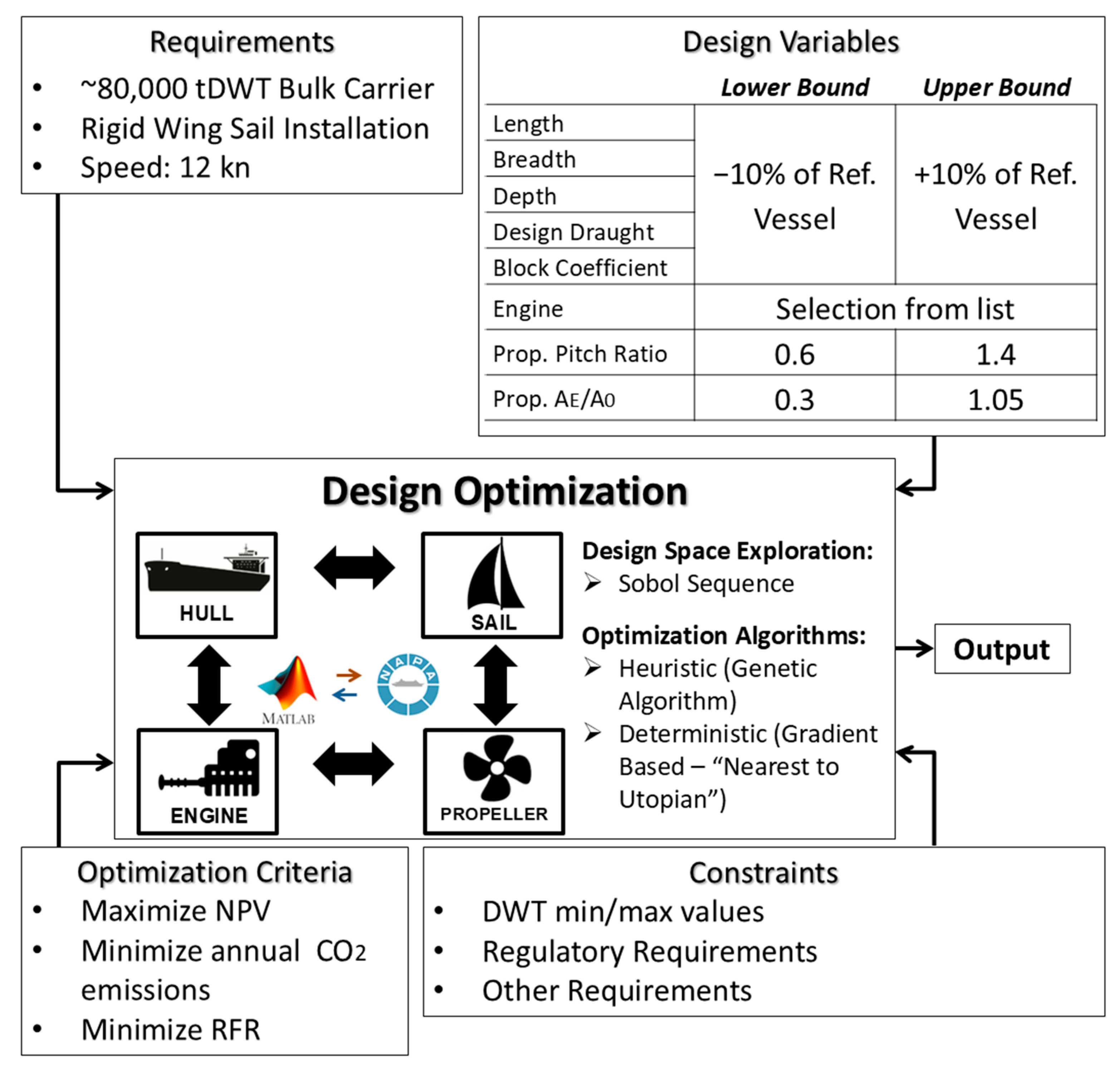
The setup of the case study defines the specific inputs and assumptions required to apply the simulation and optimization platform to a realistic design scenario. This includes the operational context, propulsion configuration, vessel characteristics, modeling resolution, optimization targets, and design variables. This enables an efficient and representative exploration of performance and economic outcomes under the influence of wind-assisted propulsion. The optimization methodology is depicted in
Figure 1.
4.1.1. Operational Route
To evaluate the performance of a wind-assisted bulk carrier under realistic environmental conditions, a transpacific route connecting China and the United States is selected, as illustrated in
Figure 2. This route reflects a commercially significant voyage that spans diverse meteorological and oceanographic zones, with varying wind and wave conditions that influence both propulsion demands and the effectiveness of WAPS.
The route is divided into 12 segments to allow localized performance estimation across discrete voyage legs. It should be noted that voyage segmentation plays a critical role in the simulation process, particularly because daily weather statistics are utilized in the performance calculations. To ensure consistency, the segmentation is ideally aligned with the vessel’s selected operating speed, such that each segment corresponds to a one-day duration. However, for the sake of simplicity and clarity in demonstration, the current study adopts a simplified segmentation scheme consisting of 12 voyage legs.
Environmental inputs for each segment—such as wind speed, wind direction, and sea state—are derived from the ERA5 dataset, developed by the Copernicus Climate Change Service (C3S). ERA5 provides hourly atmospheric reanalysis data on a global scale and is considered among the most reliable sources for long-term weather reconstruction. This ensures that each leg of the route is informed by historically representative conditions.
To account for seasonal variability and mitigate the impact of weather fluctuations on the simulation outcome, 24 distinct voyage scenarios are examined. These scenarios correspond to identical voyages initiated on different dates throughout the year 2022, thereby providing a robust statistical basis for evaluating the effect of weather conditions on WAPS performance.
Given that WAPS effectiveness is highly dependent on apparent wind speed and angle—both of which are influenced by the vessel’s course and prevailing meteorological patterns—the decision to use a fixed route without weather routing introduces a conservative bias in the results. Thus, the reported savings in fuel consumption and emissions are likely underestimated. Greater reductions could be achieved with dynamic route optimization that actively seeks favorable wind conditions.
In addition, in situations where the mean wind speed surpasses 20 m/s, the sails are considered retracted due to safety and operational constraints. Nonetheless, such high wind events are infrequent across the full voyage duration and thus are not explicitly incorporated into the present analysis.
4.1.2. Wind Propulsion System
The vessel is fitted with a rigid wing sail system, modeled after the Oceanbird concept [
20]. This system includes four wing sails, each approximately 40 m tall with an average chord length of 14 m. Aerodynamic performance data are defined through lift and drag coefficients as functions of apparent wind speed and apparent wind angle. These coefficients are processed to compute net forward thrust and lateral forces, which are incorporated into the vessel’s force equilibrium model. Sail interaction effects are not explicitly simulated, but an optimal arrangement is assumed to ensure effective operation and compliance with visibility and structural constraints.
4.1.3. Vessel Information and Design Variables
There are eight design variables: length, breadth, depth, draught, block coefficient, engine horsepower/type (selected from a predefined list), propeller pitch ratio and expanded area ratio. The design space is constrained to reflect operational, regulatory, and geometric limitations specific to this vessel category. Dimensional ratios, power requirements, and stability criteria are included as constraints in the optimization framework to ensure feasible and compliant design outcomes. During the optimization, the dimensions of the vessel are allowed to change ±10% from reference vessel assuming that there are no restrictions (e.g., port limitations).
4.1.4. Modeling Approach and Computational Resolution
To enable the efficient assessment of a large number of design alternatives, a Rapid Preliminary Assessment approach is adopted. This method relies on established semi-empirical formulas and analytical models to estimate key performance parameters, including calm water resistance, propulsion power, and aerodynamic thrust. The simulation is performed by use of the MATLAB software environment (version R2024a), without integration at first of external tools allowing for fast execution during the optimization process while maintaining sufficient fidelity for early-stage design decisions. Detailed hydrostatic, structural, and regulatory evaluations are not included in this phase but can be incorporated in future iterations or for the refinement of selected candidate designs by utilizing NAPA integration.
4.1.5. Optimization Scope
The optimization is performed for the hull form, engine selection, and propeller design, while the wind propulsion system is treated as fixed. The goal is to identify the optimal combination of these elements under the given WAPS configuration, taking into account interactions between resistance, propulsion load, and aerodynamic thrust. Engine and propeller parameters are discretized and selected from predefined sets that reflect realistic technology options. The goal is to find the optimum solution that treats all objectives with equal importance.
The developed optimization framework utilizes a structured three-step optimization methodology to identify and refine high-quality design candidates. The process consisted of: (1) Design space exploration using the Sobol sampling method to ensure uniform coverage of the feasible domain [
47]; (2) Global optimization using a genetic algorithm to identify promising Pareto-optimal solutions; and (3) Local refinement of selected designs using a gradient-based optimization algorithm for improved convergence and numerical precision.
4.1.6. Objectives
The design problem is formulated as a multi-objective optimization, simultaneously targeting three objectives:
Minimization of annual CO2 emissions, calculated based on total fuel consumption along the simulated route.
Maximization of Net Present Value (NPV), reflecting the financial profitability of the vessel investment.
Minimization of Capital Expenditure (CAPEX), including the cost of hull construction, machinery, and WAPS installation.
The outcome of the optimization is a design that improves all objective functions with equal importance using the “nearest to utopian” method that incorporates weighting factors for each objective, allowing balanced decision-making based on user-defined priorities. This design is compared to the designs that derive from optimizing each objective separately in order to observe the design trends between the different designs.
4.1.7. Constraints
To ensure realistic and regulation-compliant outcomes, the optimization framework incorporates a set of 15 design constraints. These are established to maintain technical feasibility, operational safety, and regulatory alignment throughout the design space exploration.
The constraints encompass bounds on deadweight (DWT), hull form coefficients, and dimensional ratios (such as Length/Breadth, Breadth/Draught, and Length/Draught) to ensure that the generated ship geometries remain within the typical envelope of existing bulk carrier designs, thus avoiding unrealistic configurations [
48].
Propulsion-related constraints [
49] ensure that the selected propeller operates within the engine’s power and torque envelope while avoiding unacceptable cavitation risks [
38]. Furthermore, an initial check for freeboard height [
50] and minimum propulsion power requirements [
51] are enforced based on IMO conventions. In addition, all designs must meet the 3rd phase of EEDI regulation [
3].
As an initial stability screening, a minimum intact transverse metacentric height (GM) of 3 m is imposed [
48].
The complete list of constraints applied to the bulk carrier case study is outlined below:
Min. DWT ≥ 73,835 tons (−5% from reference vessel)
Max. DWT ≤ 81,607 tons (+5% from reference vessel)
Engine limit constraint
Less than approximately 5% cavitation at the propeller
0.72 ≤ CB ≤ 0.89
0.990 ≤ CM ≤ 0.997
0.88 ≤ CWL ≤ 0.92
0.79 ≤ CP ≤ 0.84
5 ≤ L/B ≤ 7.1
2.1 ≤ B/T ≤ 3.2
10.5 ≤ L/D ≤ 12.8
IMO minimum power requirement
Freeboard constraint
GM ≥ 3 m
0.2·T ≤ propeller diameter ≤ 0.55·T.
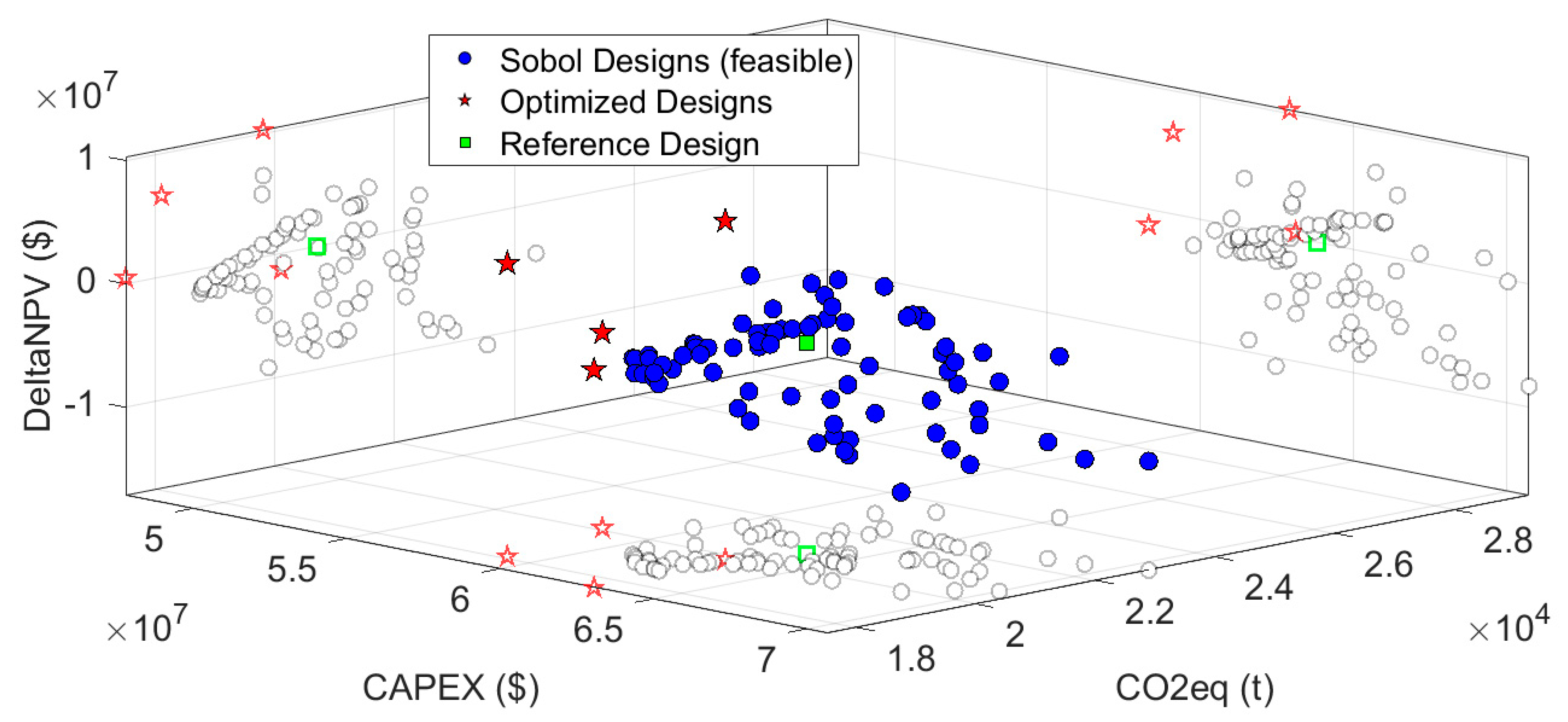
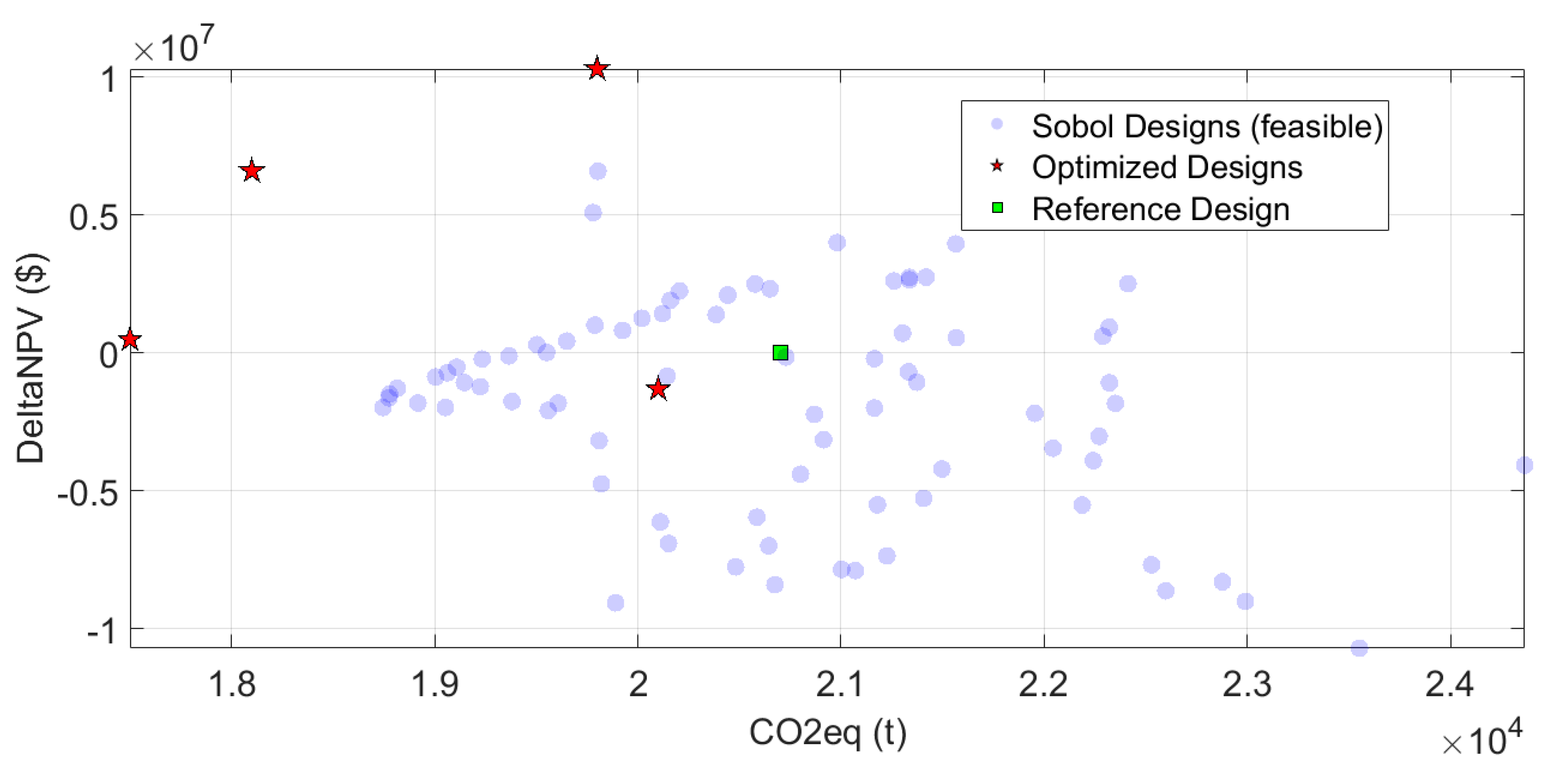
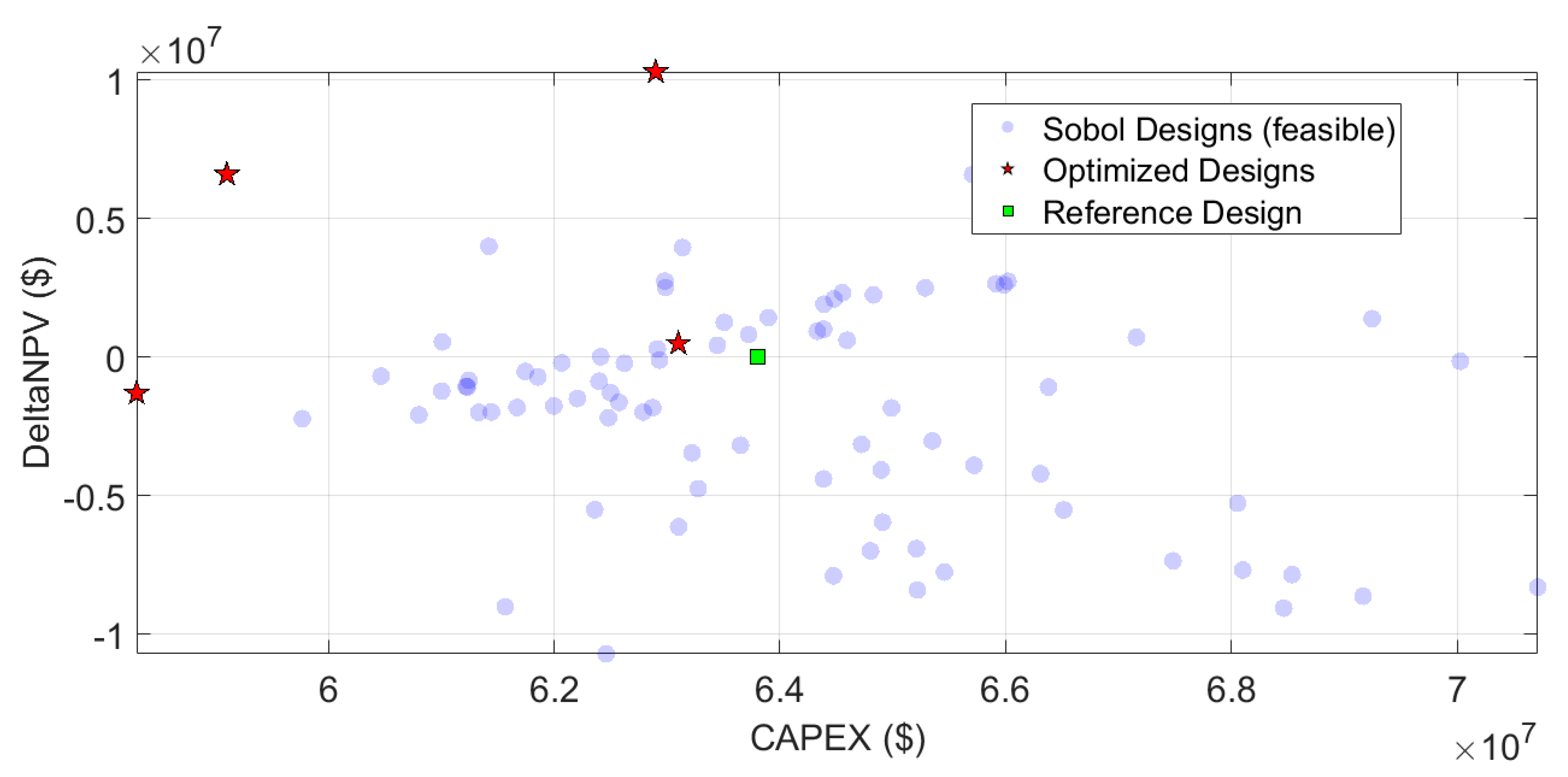
4.2. Results
The optimization yielded a diverse set of optimized designs, each representing a different trade-off between CO
2 emissions, NPV, and CAPEX. The results are presented in
Figure 3,
Figure 4,
Figure 5 and
Figure 6 and
Table 2.
In
Table 2 the optimized designs and the reference design with and without sails is presented. It can be observed that the baseline design (reference vessel without sails) has higher NPV compared to the case with sails (reference vessel with sails) but it is not meeting the EEDI phase 3 requirements, so it is an infeasible design and it is included in the table only for reference. It should be noted that the NPV is significantly influenced by the increased capital expenditure associated with WAPS installation. NPV of reference design without sails is expected to be significantly lower under a more detailed representation of regulatory compliance costs across future phases.
Analysis of the optimized designs reveals consistent trends relative to the baseline configuration. Notably, all optimized hull forms exhibit increased slenderness, reflected in a reduced block coefficient (CB), and greater design draught. Although these vessels are generally shorter in length, they are also marginally wider, which is attributed to the fact that the reference vessel was originally positioned near the upper bound of L/B ratio and CB constraints.
A strong correlation is also observed between vessel length and CAPEX, with shorter designs typically associated with lower construction costs. The inherent trade-offs among the three objective functions—CO2 emissions, CAPEX, and NPV—are clearly illustrated in the optimization results. Designs prioritizing minimum emissions tend to incur higher capital costs and reduced profitability, whereas those optimized for maximum NPV exhibit less favorable environmental performance.
Another observation is that the design optimized for minimum capital expenditure requires a higher-rated engine. This outcome stems from the vessel’s geometric characteristics—specifically its reduced length and increased block coefficient—which lead to higher propeller loading. As a result, the required propeller torque and rotational speed exceed the permissible limits of smaller engines, thereby necessitating a larger engine to satisfy engine performance constraints.
The installation of sails on the reference vessel results in an estimated CO2 emissions reduction of approximately 5.5%. However, it should be emphasized that this figure likely underestimates the true potential, as no weather routing optimization was applied in the present study.
The selected design, derived through the nearest-to-utopian methodology, represents a well-balanced solution that effectively reconciles competing objectives. This outcome demonstrates that substantial CO2 reductions are achievable without compromising economic viability, particularly when the hull form, engine configuration, and propeller are co-optimized to capitalize on the additional thrust provided by the wing sails.
5. Conclusions, Limitations and Discussion
This study presented a comprehensive simulation and optimization framework for the conceptual design of wind-assisted vessels, integrating performance modeling, regulatory compliance evaluation, and economic assessment. The platform enables simultaneous optimization of hull form, propulsion system, and wind-assisted propulsion elements, offering a practical tool for navigating the complexities of modern ship design.
Results show that even with conflicting objectives—such as minimizing emissions, reducing capital cost, and maximizing profitability—balanced improvements can be achieved through a structured optimization approach. The application of the nearest-to-utopian method led to a design that performs well across all targeted objectives.
The optimized vessel exhibited consistent design trends compared to the reference: a more slender hull, lower block coefficient, and increased draught. These modifications enhanced both hydrodynamic efficiency and the integration of wind propulsion systems.
The addition of wing sails led to a substantial reduction in CO2-equivalent emissions, easing compliance with regulations such as the EU ETS, FuelEU Maritime, and the IMO’s Net-Zero Framework. However, these savings are likely underestimated, as the study did not incorporate weather routing. The full benefit of wind-assisted propulsion can only be realized when routing adapts to prevailing wind and sea conditions.
Despite the platform’s versatility and holistic design approach, certain limitations remain. While it is well-suited for wind-assisted vessels—where the majority of the required propulsion is typically provided by the engine for most of the voyage duration—its current formulation may be insufficient for fully wind-powered vessels. In such cases, where the dominant thrust is delivered by the wind propulsion system, modeling only the surge-direction forces may not adequately capture the vessel’s dynamic behavior. Additional modeling of lateral and rotational motions (e.g., sway, yaw, and roll) may be required to accurately account for the complex aerodynamic and hydrodynamic interactions introduced by wind propulsion systems.
Finally, the developed platform serves as a practical tool for early-stage design and evaluation of vessels equipped with wind propulsion systems. Its modular architecture, compatibility with various WAPS technologies and ship types, and adaptability to different operational profiles make it especially relevant for supporting the maritime sector’s decarbonization efforts. It enables designers, engineers, and stakeholders to explore innovative configurations, assess compliance, and make informed decisions from the conceptual design phase onward.


