Article

Optimized Deployment of Generalized OCDM in Deep-Sea Shadow-Zone Underwater Acoustic Channels

1
Institute of Acoustics, Chinese Academy of Sciences, No. 21 North 4th Ring Road, Beijing 100190, China
2
University of Chinese Academy of Sciences, No. 19(A) Yuquan Road, Shijingshan District, Beijing 100049, China
3
Key Laboratory of Science and Technology on Advanced Underwater Acoustic Signal Processing, Chinese Academy of Sciences, No. 21 North 4th Ring Road, Beijing 100190, China
*
Author to whom correspondence should be addressed.
J. Mar. Sci. Eng. 2025, 13(7), 1312; https://doi.org/10.3390/jmse13071312
Submission received: 10 June 2025 / Revised: 3 July 2025 / Accepted: 5 July 2025 / Published: 8 July 2025
(This article belongs to the Section Ocean Engineering)

Abstract

Communication in deep-sea shadow zones remains a significant challenge due to high propagation losses, complex multipath effects, long transmission delays, and strong environmental influences. In recent years, orthogonal chirp division multiplexing (OCDM) has demonstrated promising performance in underwater acoustic communication due to its robustness against multipath interference. However, its high peak-to-average power ratio (PAPR) limits its reliability and efficiency in deep-sea shadow-zone environments. This study applies a recently proposed generalized orthogonal chirp division multiplexing (GOCDM) modulation scheme to deep-sea shadow-zone communication. GOCDM follows the same principles as orthogonal signal division multiplexing (OSDM) while offering the advantage of a reduced PAPR. By segmenting the data signal into multiple vector blocks, GOCDM enables flexible resource allocation, optimizing the PAPR without compromising performance. Theoretical analysis and practical simulations confirm that GOCDM preserves the full frequency diversity benefits of traditional OCDM, while mitigating PARR-related limitations. Additionally, deep-sea experiments were carried out to evaluate the practical performance of GOCDM in shadow-zone environments. The experimental results demonstrate that GOCDM achieves superior performance under low signal-to-noise ratio (SNR) conditions, where the system attains a 0 bit error rate (BER) at 4.2 dB and 6.8 dB, making it a promising solution for enhancing underwater acoustic communication in challenging deep-sea environments.

1. Introduction

The ocean covers more than 70% of the Earth’s surface, with deep-water regions exceeding depths of 3000 m accounting for over 90% of the total ocean area. The deep-sea environment hosts unique ecosystems, vast mineral resources, and numerous opportunities for scientific exploration. However, the extreme conditions of the deep sea—including high pressure, low temperatures, and complete darkness—pose significant challenges to human access and technological operations. One of the most critical challenges in deep-sea exploration is establishing reliable communication. The underwater acoustic channel is widely recognized as one of the most challenging communication media due to its inherent characteristics, including multipath propagation, scattering, high ambient noise, narrow channel bandwidth, and significant Doppler shifts [1]. Communication in the deep-sea shadow zone, compared to the deep-sea sound channel axis, is particularly difficult due to the higher propagation losses and longer multipath delays, making it a formidable technological challenge.
Given the importance of deep-sea communication, research in this field has expanded in recent years. For ocean-monitoring applications such as submarine earthquake detection, temperature and salinity measurements, and biodiversity studies, multiple sensors and devices are deployed in the deep-sea environment. Autonomous underwater vehicles (AUVs) also rely heavily on multi-user communication systems for operations such as multi-point sampling, synchronized mapping, and complex underwater tasks. A multi-user receiver designed for joint channel parameter estimation has been developed and tested in deep-sea environments [2]. To improve connectivity in deep-sea remote communication, a study in [3] demonstrated long-range acoustic transmission using large grazing angle acoustic waves, achieving error-free data transmission at rates of 15 and 7.5 bits per second over distances of 550 and 700 km, respectively, using OFDM modulation. To optimize communication performances under varying environmental conditions, an adaptive long-range underwater acoustic communication modulation method has been proposed [4]. Additionally, techniques such as space–time clustering [5] and time-reversal mirrors [6] have been explored for enhancing deep-sea acoustic communication. In [7], pseudo-random codes and wideband multiple access techniques were applied in a self-developed 6000 m acoustic release system, while [8] demonstrated that wide-beam transducers improve the SNR, thereby enhancing the performance of long-range deep-sea communication. Based on deep-sea communication characteristics, reference [9] models the deep-sea channel as two virtual users to perform channel estimation and data detection, effectively mitigating the inter-symbol interference. However, the existing deep-sea communication research has exclusively focused on sound channel axis communication and convergence zone communication, with virtually no studies addressing shadow-zone communication.
Currently, the key technologies in underwater acoustic communication include frequency hopping, direct sequence spread spectrum, single-carrier transmission, linear frequency modulation, and multicarrier modulation. Among these, OFDM has played a crucial role in terrestrial wireless communication due to its ability to counteract frequency-selective fading [10,11,12] and has also found extensive applications in underwater acoustic communication. Considering the broadband nature of underwater acoustic communication compared to radio communication, a two-step channel compensation method—comprising resampling and residual Doppler compensation—has been proposed under the assumption that the underwater acoustic channel experiences a common Doppler scaling factor across all propagation paths [13]. Low-density parity-check codes, known for their efficiency and flexibility, have also been integrated into OFDM-based underwater acoustic communication, facilitating iterative carrier frequency offset estimation, channel estimation, detection, and decoding [14]. To achieve high-data-rate transmission, MIMO technology has been incorporated into underwater acoustic communication, significantly improving both quality and reliability [15]. Subsequently, methods leveraging the sparsity of underwater acoustic channels for channel estimation have been developed [16]. When combined with equalization techniques to reduce inter-carrier interference (ICI), compressed sensing algorithms can effectively mitigate Doppler-induced channel distortions. Additionally, an ICI self-cancellation method based on index modulation has been proposed in order to further enhance underwater acoustic communication [17]. With growing interest in underwater wireless sensor networks, recent studies have explored trade-offs between underwater channel characteristics, wireless communication techniques, and overall communication quality [18].
Recently, a novel OCDM technique based on the Fresnel transform has emerged [19]. As a multicarrier modulation technique, OCDM uses chirp signals as subcarriers, achieving the same bandwidth efficiency as OFDM while maintaining compatibility with existing OFDM systems, with only a slight increase in system complexity. OCDM has been widely applied across various domains. For example, in [20], OCDM was first introduced in coherent optical communication, demonstrating superior resistance to dispersion, fading, and noise compared to OFDM.
OCDM has also shown significant promise in underwater acoustic communication. In [21], an OCDM-based system was evaluated and compared with traditional OFDM systems in underwater acoustic channels, and the experimental results show that OCDM offers superior robustness. To further optimize its performance for underwater applications, various techniques have been integrated with OCDM. For instance, a data-pick-based RAKE receiver has been designed to maintain reliable communication even with short guard intervals [22], while the incorporation of index modulation techniques has improved the system’s interference resistance [23]. Furthermore, combining OCDM with MIMO technology has been shown to enhance diversity, effectively mitigating channel fading [24]. Given its advantages, OCDM has been successfully applied to various underwater acoustic communication applications, including the underwater Internet of Things (IoT) [25] and sonar communication integration [26].
However, similar to OFDM, OCDM also suffers from a high PAPR. This issue arises because the superposition of multiple subcarriers in multicarrier modulation schemes can create peaks at certain moments, placing significant demands on the power amplifier. When the signal peaks enter the nonlinear region of the power amplifier, distortion occurs, leading to performance degradation. Additionally, the noise power in oceanic environments is generally higher than in wireless communications, and the received signal power in shadow-zone communication is particularly unstable and significantly lower than that in sound channel axis communication. This necessitates a higher transmission power, further emphasizing the importance of PAPR reduction to ensuring an efficient power amplifier operation and improving the overall system performance. Several methods have been proposed to mitigate PAPR, including amplitude modulation, partial transmit sequences, virtual carriers, PAPR constraints, and precoding techniques [27,28,29]. A modulation scheme known as OSDM, which divides the transmission frame into multiple vectors, has been shown to effectively reduce PAPR [30,31,32,33,34]. OSDM achieves partial frequency diversity on each subcarrier, whereas OCDM provides frequency diversity across the entire bandwidth for each subcarrier. Recently, a new modulation scheme, GOCDM, has emerged [35]. Similar to OSDM, GOCDM possesses PAPR reduction capabilities while combining the advantages of both OSDM and OCDM.
This paper applies GOCDM to deep-sea shadow-zone communication. The main contributions of this work are as follows:
(1)
The impact of broadband Doppler effects on the OCDM system in underwater acoustic communication is analyzed.
(2)
A GOCDM-based underwater acoustic communication system, including transmitter and receiver design, is proposed. By deriving the system model, a theoretical analysis demonstrates that GOCDM inherits the full subcarrier frequency diversity and multipath resilience advantages of OCDM. Simulations confirm GOCDM’s effectiveness in mitigating multipath effects and reducing the PAPR, as well as evaluating the impact of the carrier frequency offset on these modulation schemes.
(3)
Deep-sea experiments were conducted to evaluate the performance of OFDM, OCDM, and GOCDM in shadow-zone communication. To the best of our knowledge, this is the first experimental demonstration of shadow-zone communication using the bottom-bounce method. The results demonstrate that GOCDM outperforms the other two schemes in low-SNR, complex multipath deep-sea environments.
The remainder of this paper is organized as follows. Section 2 presents the fundamental model of the deep-sea shadow-zone channel and OCDM, analyzing the effects of multipath propagation and Doppler shifts on OCDM in practical underwater acoustic communication. Section 3 introduces the GOCDM system, examining its performance in an ideal multipath channel and detailing the transmitter and receiver architecture for underwater acoustic communication. Section 4 presents simulation results, while Section 5 provides deep-sea experimental results and performance evaluations. Section 6 discusses transmission rates and computational complexity.
Notations: H , T , 1 , and     denote the Hermitian transpose, transpose, matrix inverse, and l 2 norm, respectively. denotes the Kronecker product, I M represents an M-dimensional identity matrix, and e M m indicates the m-th column of the M-dimensional identity matrix. eig represents the eigenvalues of the matrix, mod a , b denotes the remainder when a is divided by b, and ceil indicates the ceiling function.

2. Research Foundation

The strong multipath resistance of the OCDM system makes it well-suited for underwater acoustic channels, which exhibit complex multipath characteristics. However, like OFDM, OCDM suffers from a high PAPR, which is incompatible with the low SNR typical of deep-sea shadow-zone channels. This section first provides an overview of the characteristics of deep-sea shadow-zone channels, followed by a description of the OCDM modulation scheme and an analysis of the impact of broadband Doppler effects on OCDM systems in underwater acoustic communication.

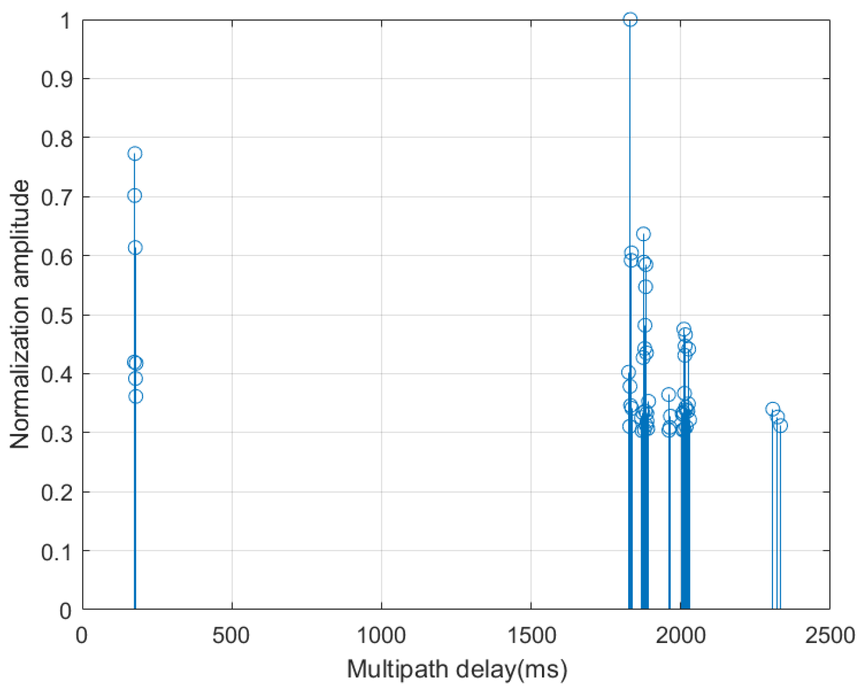
2.1. Characteristics of Deep-Sea Shadow-Zone Channels

When a sound source and hydrophone are positioned near the deep-sea surface, distinct convergence zones and shadow zones can be observed. In convergence zones, the intensity of the sound field can exceed that of a spherical spreading sound field by approximately 25 dB, as explained by normal mode theory [36]. Between these convergence zones, sound waves experience a significantly greater propagation loss than in spherical spreading conditions, forming a region known as the acoustic shadow zone, as illustrated in Figure 1.
Despite its name, the shadow zone is not entirely devoid of sound waves. Due to environmental factors such as surface waveguides and mesoscale oceanic phenomena, a fraction of the sound energy can enter the shadow zone through scattering and diffraction. However, this energy is relatively weak, highly susceptible to hydrological variations, and characterized by significant uncertainty. Additionally, sound waves can enter the shadow zone through seabed reflections, typically propagating along four primary paths: seabed reflection, seabed–surface reflection, surface–seabed reflection, and surface–seabed–surface reflection.
As the distance between the transmitter–receiver, the depths of the sound source and hydrophone, and the seabed depth vary, the multipath time delays among these different propagation paths also change. Furthermore, sound waves entering the shadow zone via reflection are significantly affected by the material composition of seabed sediments and seabed morphology, leading to additional uncertainties in signal propagation.
In summary, the low SNR at the receiver remains a major challenge for communication within the shadow zone.

2.2. Fundamentals of OCDM

OFDM is implemented using the Discrete Fourier Transform (DFT), where each subcarrier occupies only a portion of the total bandwidth. In contrast, OCDM is based on the Discrete Fresnel Transform (DFnT), where each subcarrier is a chirp signal that spans the entire bandwidth.
Chirp signals are widely used in underwater acoustic spread-spectrum communication, as they enhance reliability at the expense of spectral efficiency. OCDM employs multiple sets of orthogonal chirp signals as subcarriers, with each subcarrier extending across the full bandwidth. Similar to OFDM, OCDM can modulate information onto the amplitude and phase of its subcarrier. The core DFnT matrix of OCDM is defined as follows:
Φ N m , n = 1 N e j π 4 × e j π N m n 2 N 0   mod   2 e j π N m + 1 2 n 2   N 1     mod   2 ,
where N is the size of the square matrix.

2.3. Impact of Non-Uniform Doppler Effects on OCDM

Underwater acoustic channels are subjected to non-uniform Doppler effects, which can significantly impact the performance of OCDM systems. The following analysis examines the influence of non-uniform Doppler effects on OCDM signal transmission.
Let d(k), where k = 0, 1, 2, …, N − 1, represent the transmitted data symbols, and let g(t) denote the window function. The transmitted OCDM signal can then be expressed as follows:
s ( t ) = Re k = 0 N 1 d k e π 4 e j π N T 2 t k T N 2 g t e j 2 π f c t ,
where f c is the carrier frequency, T is the OCDM symbol duration, and the time-varying path delay of the underwater acoustic channel is denoted as τ p t = τ 0 α t . The received signal can be expressed as follows:
y ( t ) = Re p = 1 P A p   e j 2 π f c t + α t τ 0 p × k = 0 N 1 d k e π 4 e j π N T 2 t + α t τ 0 p k T N 2 g t + α t τ 0 p + w t .
After down-conversion, the baseband signal is given by the following:
y b ( t ) = p = 1 P A p e j 2 π f c τ 0 p g t + α t τ 0 p   × k = 0 N 1 d k e π 4 e j π N T 2 1 + α 2 t τ 0 p 1 + α k T N ( 1 + α ) 2 e j 2 π f c α t + w t .
where α represents the Doppler scaling factor, primarily caused by vessel motion. From the above equation, it can be observed that the chirp rate of each subcarrier in the received OCDM signal becomes 1 + α 2 times the original rate, leading to a change in subcarrier spacing:
f i = 1 2 π d d t π N T 2 1 + α t k T N 2 π N T 2 1 + α t k + 1 T N 2 = Δ f 1 + α .
It can be observed that the subcarrier spacing changes from ∆f to ∆f(1 + α), which is the same as in OFDM.
From this analysis, it is evident that the non-uniform Doppler effect in underwater acoustic communication has a significant impact on the OCDM system. To mitigate this effect, a two-step method, as proposed in [13], can be employed for Doppler equalization.

3. GOCDM Underwater Acoustic Communication System

GOCDM is an extended form of OCDM. We first present the modulation scheme of GOCDM, followed by a proof that it retains the same convolutional properties as OCDM and exhibits complete frequency band diversity for the subcarriers. We then introduce its application in transmitter and receiver systems for underwater acoustic communication.

3.1. GOCDM Modulation and Demodulation

Assume that a symbol block of length K, denoted as d = d 0 , d 1 , , d K - 1 T , is transmitted. This block is divided into N symbol vectors, each of length M, and arranged into an N × M matrix following a row-wise allocation method. Each column of this matrix is then subjected to an Inverse Discrete Fresnel Transform (IDFnT), after which the transformed data is read out row by row to obtain the transmitted signal, denoted as s. This entire process can be mathematically expressed using a formula. As shown in [33], a K × K permutation matrix is defined to represent this operation.
P N , M = I N e M T 0 I N e M T 1 I N e M T M 1 ,
The modulation scheme for GOCDM can thus be expressed as follows:
s = P N , M H I M Φ N H P N , M d = Φ N H I M d .
Similar to OSDM, GOCDM allows for adjustments to the parameters M and N. When M = 1, the system reduces to OCDM, and, when M = K, the system becomes Single-Carrier Frequency-Domain Equalization (SC-FDE). As a multicarrier modulation technique evolved from OCDM, GOCDM also requires the addition of a cyclic prefix. After removing the cyclic prefix at the receiver, the received signal r is obtained. The demodulation process is the inverse of the modulation process. Specifically, the signal r is first arranged row by row into an N × M matrix; then, DFnT is applied to each column of this matrix. The matrix is then read out row by row to obtain the demodulated signal y. The demodulation process can also be mathematically expressed as follows:
y = P N , M H I M Φ N P N , M r = Φ N I M r .
Let the demodulation matrix of GOCDM be denoted as Ψ. Since the DFnT matrix is a unitary matrix, it follows that
Ψ K 1 = Φ N I M 1 = Φ N 1 I M = Φ N H I M = Φ N I M H = Ψ K H ,
The above equation utilizes the property that the inverse of the Kronecker product of two matrices equals the Kronecker product of their respective inverses. From this equation, it is evident that Ψ K is also a unitary matrix, with its inverse given by Φ N H I M , which corresponds to the modulation matrix Ψ K H . In this paper, GOCDM is applied to the underwater acoustic communication system, and the flowchart is shown in Figure 2.

3.2. Properties of GOCDM

Building upon the methodology of [13], the complete receiver system workflow employed in this paper consists of the following: Doppler factor estimation-resampling-carrier frequency offset estimation-carrier frequency offset equalization-channel estimation-channel equalization. After completing the aforementioned four steps, the channel matrix can be approximately treated as a circulant matrix. We then analyze the properties of the GOCDM modulation and demodulation method based on the circulant matrices.
Assuming that the cyclic prefix of the signal is sufficiently long, the ideal multipath channel matrix can be represented as a circulant matrix H K . Neglecting the impact of noise, the signal modulated by GOCDM and transmitted through the ideal multipath channel can be expressed as follows:
y = Φ N I M H K Φ N H I M d = Ψ K H K Ψ K H d .
To analyze the properties of the GOCDM modulation matrix Ψ K with respect to the circulant matrix, consider the matrix product H ^ K = Ψ K H K Ψ K H . For simplicity, in the following proof, all matrix and vector indices will start from 1.
To obtain the value in the m-th row and n-th column of matrix H ^ K m , n , the m-th row of Ψ K H K must be multiplied by the n-th column of Ψ K H . The n-th column of Ψ K has a non-zero value only at the row index, mod n , M , mod n , M + M , , mod n , M + N 1 M , which corresponds to the ceil(n/M)-th column of Φ N H . Let matrix Ψ K H K be represented as H ˜ K ; then, H ^ K m , n can be expressed as follows:
H ^ K m , n = k = 0 N 1 H ˜ K m , mod n , M + k M Φ N H k + 1 , ceil n M ,
To obtain H ˜ K m , mod n , M + N 1 M , similar to the previous step, the m-th row of Ψ K needs to be multiplied by the mod n , M + N 1 M -th column of H K . Since the m-th row of Ψ K has a non-zero value only at the column index, mod m , M , mod m , M + M , , mod m , M + N 1 M , which corresponds to the ceil(m/M)-th row of Φ N , H ˜ K m , mod n , M + k M can be expressed as follows:
H ˜ K m , mod n , M + k M = v = 0 N 1 Φ N ceil m M , v + 1 × H K mod m , M + v M , mod n , M + k M .
Substituting (12) into (11), we obtain the following:
H ^ K m , n = k = 0 N 1 v = 0 N 1 Φ N ceil m M , v + 1 × H K mod m , M + v M , mod n , M + k M × Φ N H k + 1 , ceil n M .
Next, extract all elements from H K with row indices mod m , M , mod m , M + M , , mod m , M + N 1 M and column indices mod n , M , mod n , M + M , , mod n , M + N 1 M , and arrange them in sequence to form a new matrix H N , where the element in the a-th row and b-th column of H N can be expressed as follows:
H N a , b = H K mod m , M + a 1 M , mod n , M + b 1 M ,
H N is also a circulant matrix, which allows (13) to be simplified as follows:
H ^ K m , n = Φ N ceil m M , : H N Φ N H : , ceil n M .
According to the linear convolution properties of the Fresnel transform described in Section 2, we obtain the following:
H ^ K m , n = H N ceil m M , ceil n M = H K mod m , M + ceil m M 1 M , mod n , M + ceil n M 1 M = H K m , n .
Therefore, the GOCDM modulation and demodulation matrix through the ideal multipath channel can be expressed as follows:
H ^ K = Φ N I M H K Φ N H I M = Ψ K H K Ψ K H = H K .
From the above expression, it can be observed that the GOCDM modulation method retains the same properties as the OCDM modulation method under circulant matrices. This indicates that, for ideal multipath channels, the proposed GOCDM modulation method inherits the multipath resistance performance of OCDM.
Similarly, based on the modulation and demodulation matrices of OCDM with circulant matrices, the linear convolution properties of the GOCDM transform can be derived. Assume three matrices S, H, and Ψ, where S and H are circulant matrices. By modulating the convolution of s and h with Ψ, we obtain the following:
r ^ = Ψ r = Ψ H Ψ H Ψ s = Ψ S Ψ H Ψ h = H Ψ s = H s ^ = S Ψ h = S h ^ ,
Thus, the GOCDM demodulation matrix also preserves the linear convolution properties.

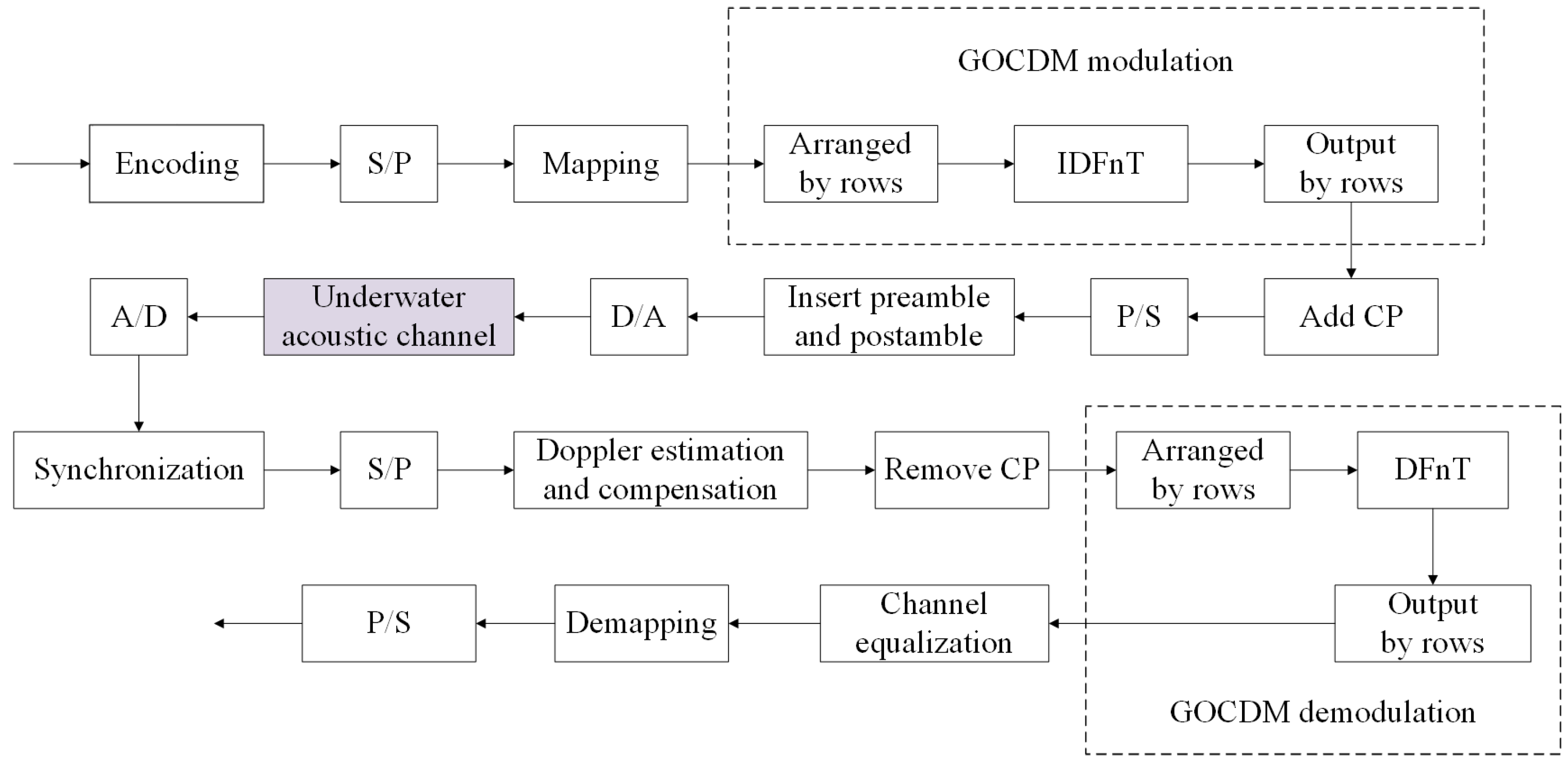
3.3. Underwater Acoustic Communication GOCDM System

The first part of this section introduced the modulation and demodulation methods of GOCDM. To apply GOCDM in an underwater acoustic communication system, channel estimation and equalization are also necessary. After performing essential synchronization, Doppler scaling factor estimation, nonuniform Doppler compensation via resampling, carrier frequency offset estimation, and carrier frequency offset compensation at the receiver [13], the effects of other noise in the marine environment can be approximated as additive white Gaussian noise. Under this assumption, the received signal can be expressed as follows:
y = Ψ K H K Ψ K H d + Ψ K w = H K d + v ,
where w represents Gaussian white noise. Since Ψ is a unitary matrix, v can also be regarded as Gaussian white noise. When using block pilots for channel estimation, the received signal can be expressed as r = P K h + z , where P K is a circulant matrix with the pilot sequence p as its first column, and h is the time-domain response vector of the channel. Least Squares (LS) and Minimum Mean Square Error (MMSE) methods can be applied for channel estimation; however, both methods suffer from a high computational complexity. Alternatively, a sparse channel estimation method can be employed by appropriately designing the pilot sequence, though this approach requires prior knowledge of the exact number of channel multipaths. Another efficient approach leverages the flexibility of GOCDM by setting the modulation parameter M of the estimation sequence to 1, assigning a value to only one subcarrier in the pilot sequence, thereby transforming the pilot sequence into a chirp signal and enabling the use of the channel estimation method described in [37].
Similar to OCDM, GOCDM supports low-complexity equalization algorithms. By performing a direct FFT on the received signal, we obtain the following:
x = F K H K Ψ K H d + F K w .
By utilizing the property whereby a circulant matrix can be diagonalized by the DFT matrix, two IFFT and FFT operations are inserted in the middle of the above equation:
x = F K H K F K H F K Ψ K H F K H F K d + v = Λ K T K H F K d + v ,
where Λ K = F K H K F K H is the channel frequency response, and T K H = F K Ψ K H F K H is the coefficient matrix. It follows from the above equation that each subcarrier in the GOCDM modulation scheme achieves full diversity across the frequency band.
Given that, for the DFnT matrix [19], Γ K H = F K Φ K H F K H , the diagonal matrix Γ K contains the eigenvalues of the DFnT matrix relative to the IDFT matrix, given by the following:
Γ K k = e j π N k 2 .
To determine the coefficient matrix, the eigenvalues of Ψ K relative to the IDFT matrix must be known. Since Φ N is a symmetric matrix, the following property holds for symmetric matrices:
eig Φ N I M = eig Φ N eig I M T
Thus, the coefficient matrix T K is given by the following:
T K k = e j π N k 2 k = 0 , 1 , , N 1 e j π N mod k , N 2 k = N , N + 1 , , N M .
To equalize the signal, the phase shift caused by the diagonal matrix T K must first be removed. Then, the channel equalization matrix R K is applied to compensate for the channel effects. Finally, the signal undergoes an IFFT, as follows:
d ^ = F K H R K T K x = F K H R K T K Λ K T K H F K d + F K H R K T K v = F K H R K Λ K F K d + F K H R K T K v ,
The equalization matrix R K is a diagonal matrix. For zero-forcing (ZF) equalization,
R K k = Λ K 1 k ,
and, for minimum mean square error (MMSE) equalization,
R K k = Λ K k Λ K k 2 + ρ 1 ,
where ρ is the signal-to-noise ratio (SNR).

4. Simulation

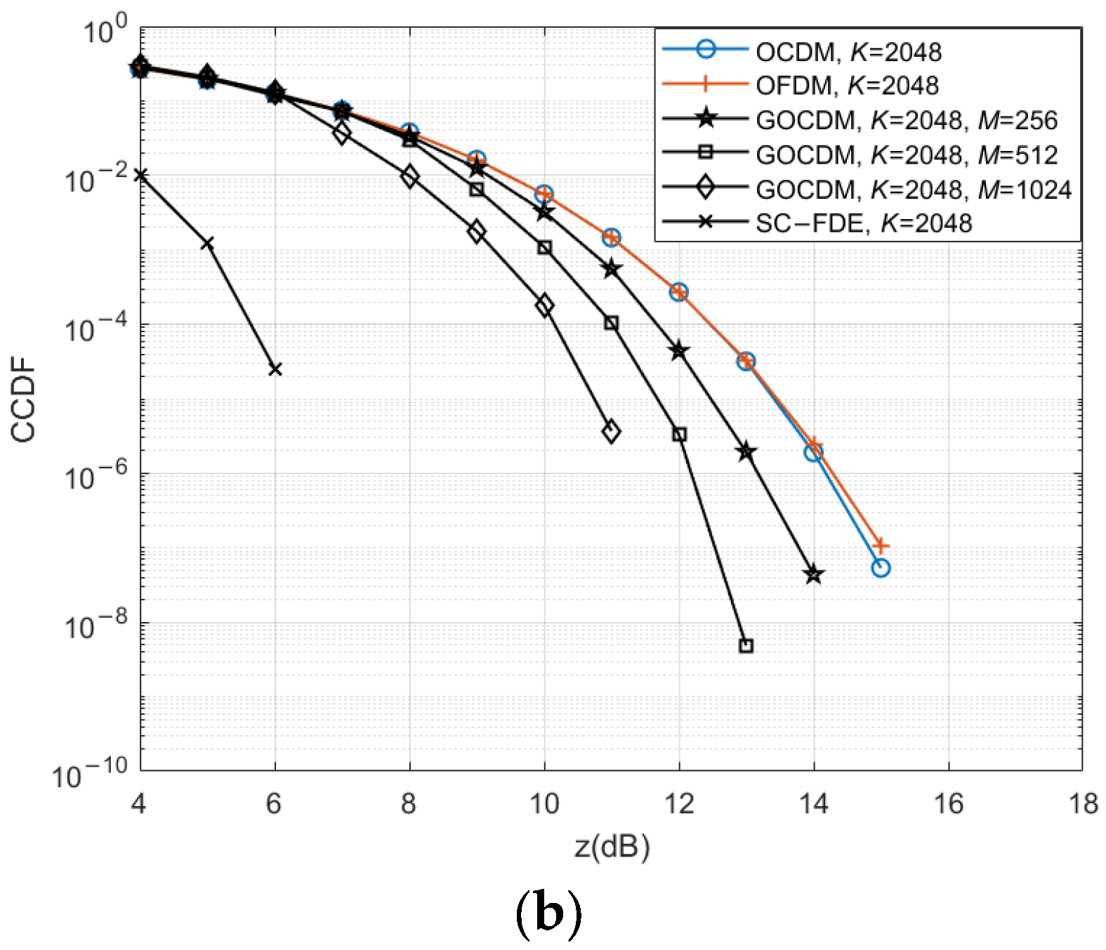
4.1. Peak-to-Average Power Ratio Performance

In this subsection, we evaluate the PAPR performance of GOCDM through simulations. In deep-sea communication, a relatively high number of subcarriers is typically required in order to counteract the long multipath delay of the channel. We consider two cases, with subcarrier counts of 1024 and 2048. For the 1024-subcarrier case, we simulate three scenarios with M = 128, M = 256, and M = 512. For the 2048-subcarrier case, we use M = 256, M = 512, and M = 1024. The modulation scheme used is QPSK.
We analyze the PAPR performance of different modulation schemes using the Complementary Cumulative Distribution Function (CCDF), which represents the probability that the root mean square of the signal’s PAPR exceeds a given threshold z. As shown in Figure 3, the PAPR of GOCDM is consistently lower than that of conventional OFDM and OCDM. In Figure 3a, it is evident that conventional OFDM and OCDM exhibit the same PAPR characteristics. However, the proposed GOCDM method significantly reduces the PAPR compared to these conventional schemes. Specifically, for cases where the PAPR exceeds 12 dB, increasing the M leads to a reduction in the probability of high PAPR occurrences in GOCDM modulation by 1 to 3 orders of magnitude compared to OFDM and OCDM.
When M is set to K, GOCDM evolves into SC-FDE and simultaneously transitions from multicarrier modulation to single-carrier modulation, whereby the PAPR reaches its minimum value. Subsequently, we compared other performance aspects of the communication system under different M values and summarized the findings in Section 6. Users may adjust the M value based on practical requirements to achieve optimal performance.
In deep-sea shadow-zone communication, the signal-to-noise ratio (SNR) at the receiver is typically low, and the high-power portions of signals with a high PAPR are more susceptible to medium non-uniformities, such as density variations in the thermocline. This can lead to increased energy loss, refraction, or reflection. Conversely, the lower-power portions of the signal may lack sufficient energy to penetrate these non-uniform regions, resulting in inconsistent signal attenuation across different power levels and increasing transmission uncertainty. Overall, the reduced PAPR of GOCDM makes it particularly well-suited for deep-sea shadow-zone communication.

4.2. Performance in an Ideal Multipath Channel

In this subsection, we evaluate the performance of GOCDM in an ideal multipath channel. The simulation is based on a measured deep-sea shadow-zone communication channel, as depicted in Figure 4. Since this subsection focuses solely on an ideal multipath channel, time-varying effects are not considered. We simulate two cases with subcarrier counts of 1024 and 2048, respectively. When the number of subcarriers is 2048, the cyclic prefix is longer than the channel’s multipath delay, ensuring an ideal multipath channel condition. Conversely, when the number of subcarriers is 1024, the cyclic prefix is shorter than the channel’s multipath delay, allowing for a comparison of different modulation schemes under conditions where the cyclic prefix is insufficient.
The results are presented in Figure 5. From Figure 5a, it can be observed that GOCDM exhibits performance similar to OCDM. This is because GOCDM inherits the advantages of conventional OCDM, where subcarriers achieve full frequency diversity, as theoretically analyzed in Section 3. In Figure 5b, when the cyclic prefix is insufficient, both GOCDM and OCDM experience significant performance degradation, while OFDM shows less degradation. This is because, compared to OCDM, OFDM demonstrates better robustness in frequency-selective fading conditions with poor channel estimation.
Additionally, in Figure 5b, the BER curves of OCDM and GOCDM do not coincide. When the cyclic prefix is insufficient, the leading portion of each data block is affected. As N decreases, the proportion of original data impacted by GOCDM-modulated data decreases; however, the severity of the impact increases. Particularly when M equals K, GOCDM degenerates into SC-FDE, where the initial few information bits of each data block suffer severe interference. At lower signal-to-noise ratios, the SNR constitutes the dominant factor affecting bit error rates, rendering the impact of different M values on BER negligible. Conversely, at higher SNR levels, inter-symbol interference dominates as the primary error contributor. As a single-carrier modulation scheme, SC-FDE experiences the most severe inter-symbol interference, consequently exhibiting a higher BER. Therefore, selecting an appropriate N based on the specific multipath delay characteristics is crucial. The constellation diagrams for K = 2048 and an SNR of 25 dB are shown in Figure 6. From these diagrams, it is evident that both OCDM and GOCDM offer superior resistance to multipath interference compared to OFDM.

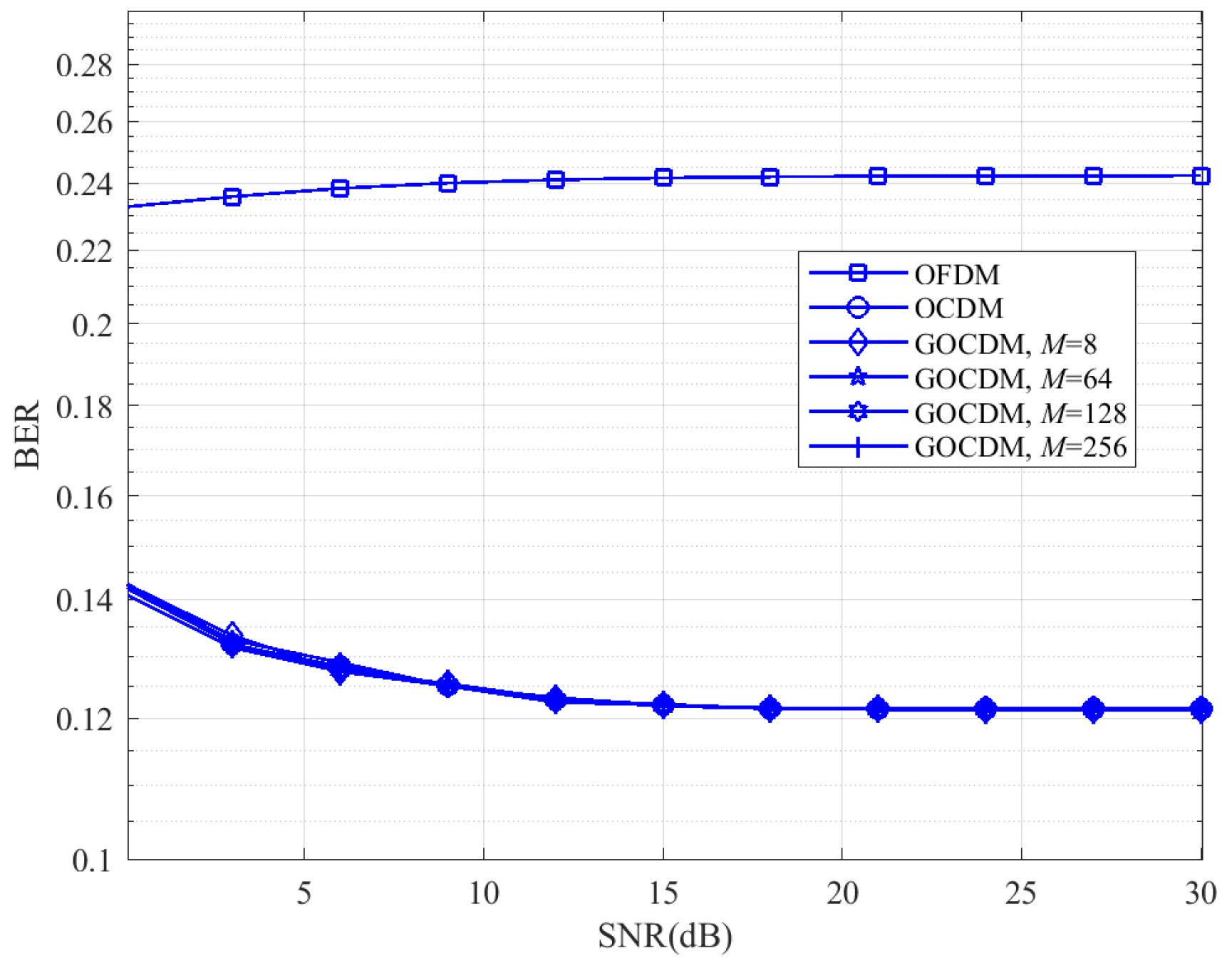
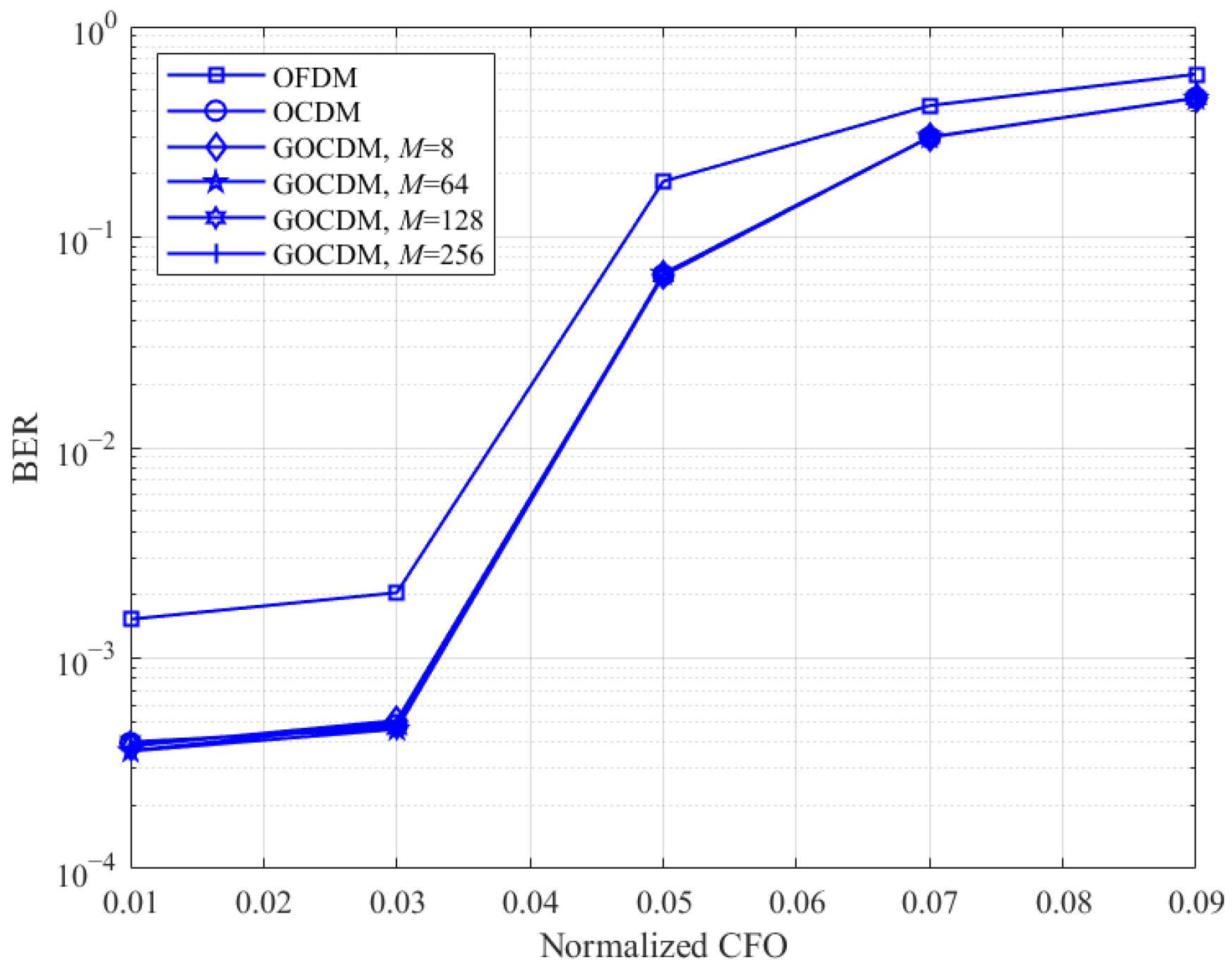
4.3. Impact of Doppler Shift

In this subsection, we evaluate the impact of Doppler effects on OFDM, OCDM, and GOCDM using the deep-sea shadow zone channel described in the previous subsection. First, a normalized Doppler shift of 0.1 is introduced, and no equalization is applied to observe the direct impact of the Doppler shift on the different modulation schemes. The simulation results are presented in Figure 7. It is evident that theDoppler shift severely affects all modulation schemes, with OCDM and GOCDM exhibiting similar levels of degradation. However, compared to OFDM, both OCDM and GOCDM maintain superior performance under Doppler-induced distortions.
Next, we investigate the impact of different Doppler shifts on communication performance. The results, shown in Figure 8, indicated that, as the Doppler shift increases, all modulation schemes experience significant degradation. The degree of impact is similar across all schemes, confirming the theoretical conclusions presented in Section 2.

5. Deep-Sea Experiment

To validate the performance advantages of the GOCDM underwater acoustic communication system, a deep-sea experiment was conducted in the waters adjacent to China at a location with an average depth of approximately 5000 m. Utilizing the deep-sea channel propagation characteristics introduced in Section 2 and carefully controlling the transmission–reception distance ensured that the receiving hydrophone remained within the shadow zone. Both the transmitting and receiving vessels traveled at speeds ranging from 3.8 to 5.0 knots, introducing a significant Doppler effect. The transducer depth varied between 80 and 94 m, while the hydrophone depth ranged from 307 to 360 m. Based on these conditions, the channel in this experiment can be classified as a deep-sea shadow zone channel.
Communication was conducted using OFDM, OCDM, and GOCDM, with all other parameters kept consistent. The number of subcarriers was set to 1024, and the sampling rate was 50 kHz. Table 1 provides a summary of the transmitted signal parameters and experimental result.
A portion of the received signal spectrum is shown in Figure 9. The first segment consists of an OCDM signal with a single carrier, which can be regarded as a linear frequency modulation signal and serves as a pilot for channel estimation. The latter part contains GOCDM-modulated data signals. The spectrum indicates that the received signal exhibits a low SNR due to the shadow zone reception, consistent with the theoretical analysis presented earlier in this paper.
The multipath delay characteristics for the three propagation paths considered in this experiment are shown in Figure 10, with results summarized in Table 2. Figure 10a illustrates the A–B channel multipath response, showing that the acoustic energy arriving via scattering, refraction, and multiple reflections is almost entirely attenuated, leaving only a single cluster of seabed reflection paths. This results in the lowest received signal SNR. Figure 10b presents the C–D channel multipath response, where the initial cluster is presumed to correspond to paths formed by scattering and diffraction. The channel exhibits a longer overall multipath delay and a more complex multipath structure, with a relatively higher received SNR. Figure 10c shows the E–F channel multipath response, where most of the acoustic energy arriving via scattering and diffraction is significantly attenuated. The remaining two propagation paths likely correspond to seabed reflection and combined seabed–surface reflection.
According to the simulation results in Section 4, the Doppler effect impacts all three modulation schemes similarly. Therefore, despite the high Doppler factor in this experiment, it does not significantly affect the comparative performance of the modulation schemes. As shown in Table 2, when the received SNR is 4.2 dB and 6.8 dB, only GOCDM achieves a BER of zero, while OCDM shows a lower BER than OFDM due to its superior multipath resistance. GOCDM inherits the multipath resistance of OCDM while significantly reducing the PAPR compared to both OFDM and OCDM, making it particularly advantageous for low-SNR environments such as deep-sea shadow-zone communication. It is worth noting that, although SC-FDE achieves the lowest PAPR, its resistance to inter-symbol interference is relatively low as a single-carrier modulation scheme, resulting in a less effective performance in high-delay shadow-zone communications.
At an SNR of 0.016 dB, the BER of OFDM is lower than that of OCDM. Under extremely poor channel conditions, the channel estimation and equalization degrade significantly, and the frequency-selective fading characteristics of OFDM result in a lower BER than OCDM. However, because the low SNR has a reduced impact on GOCDM, its channel estimation and equalization performance are enhanced, enabling it to fully leverage its multipath resistance capabilities. Meanwhile, given that this channel lacks multiple reflection paths and exhibits a low multipath delay, SC-FDE demonstrates a notably high performance with a bit error rate of merely 0.06.
In summary, this deep-sea experiment demonstrates that the proposed GOCDM modulation technique effectively reduces the PAPR while improving the resistance to multipath effects. These advantages make GOCDM well-suited for deep-sea shadow-zone communication, where the received signal SNR is low, and multipath conditions are complex. Additionally, we need to determine the optimal value of M for GOCDM by considering both the communication distance and transmit power in order to achieve the best communication performance.

6. Discussion

6.1. Performance Analysis

Let the modulation order be denoted as M and the channel coding rate as R c . The transmission rate for a single GOCDM block is, then, given by R s = N R c log 2 M T CP T T CP + T .
Next, the computational complexity of the GOCDM underwater acoustic communication system is analyzed. Since GOCDM modulation applies a DFnT to MN-dimensional vectors, the computational complexity at the transmitter is O ( M N   log 2   N ) , lower than OCDM and OFDM. At the receiver, channel equalization requires a K-point FFT, resulting in a computational complexity of O K   log 2   K . It follows that the computational complexity of GOCDM remains comparable to that OFDM and OCDM, ensuring practical feasibility in underwater acoustic communication systems.
We then include SC-FDE in the discussion. At the receiver side, the implementation complexity of SC-FDE is identical to that of GOCDM, with both being O K   log 2   K . On the transmitter side, SC-FDE requires a pulse-shaping filter. Assuming the filter order is P, SC-FDE exhibits an additional complexity of K P 1 2 K   log 2   K compared to OFDM. Furthermore, to mitigate inter-symbol interference, SC-FDE needs to increase the symbol duration, which, consequently, reduces the transmission rate to some extent.
The performance comparison between SC-FDE and OCDM has been thoroughly discussed in [19]. Specifically, OCDM is equivalent to SC-FDE when the cyclic prefix is sufficient, while OCDM outperforms SC-FDE when the channel multipath delay exceeds the cyclic prefix length. This advantage stems from OCDM’s multicarrier nature, which distributes the localized interference across all subcarriers to mitigate its impact when the partial time-domain signals are corrupted. Similarly, GOCDM inherits this advantage as a multicarrier scheme. In contrast, SC-FDE, being a single-carrier system, lacks this capability and, consequently, suffers a significant performance degradation under excessive multipath delay conditions.

6.2. Summary and Future Research Recommendations

The simulation and sea trial results demonstrate that GOCDM achieves a remarkable performance in deep-sea shadow-zone communication. Since the trials were conducted in winter when surface ducts rarely form, only bottom-bounce sound channels existed during shadow-zone communication, resulting in relatively short overall channel delays—a favorable condition for communication. However, during summer shadow-zone communication, surface ducts are highly likely to exist, and signals may also reach the shadow zone through scattering. Under such conditions, the total channel delay could extend to several seconds, significantly degrading communication performance. Therefore, I suggest that further research should first focus on designing an appropriate frame structure to address these long delays, and then we should conduct simulations using tools like Bellhop. Subsequently, we should conduct a series of sea trials under summer conditions with surface ducts to validate system performance.

7. Conclusions

To address the challenges of a low SNR and complex multipath propagation in deep-sea shadow-zone communication, this study applies GOCDM to underwater acoustic communication systems, and performed deep-sea shadow-zone communication trials. The results confirm that GOCDM inherits the benefits of both OCDM and OSDM while mitigating their respective drawbacks. Both simulations and experimental results demonstrate that applying GOCDM to deep-sea shadow area communication significantly reduces the bit error rate and improves system performance. Future research can focus on the clustering characteristics of underwater acoustic communication methods in deep-sea shadow zones, further analyzing the energy distribution and time delay characteristics of scattered and reflected acoustic signals. Additionally, designing more optimized underwater acoustic communication systems based on these insights could enhance communication reliability and efficiency in challenging underwater environments.

Author Contributions

Literature search, H.Y. and C.C.; figures, H.Y.; study design, H.Y., C.C., Y.F., Z.P., W.W. and L.Y.; data collection, H.Y., C.C., Y.F., Z.P., W.W., L.Y., Y.L. and H.H.; data analysis, H.Y. and C.C.; data interpretation, H.Y.; writing, H.Y.; resources, C.C., Y.L. and H.H.; project administration, C.C., Y.L. and H.H. All authors have read and agreed to the published version of the manuscript.

Funding

This research was funded by the National Natural Science Foundation of China, grant number E3111301. The APC was funded by internal research grants from the Institute of Acoustics, Chinese Academy of Sciences.

Data Availability Statement

The data presented in this study are available upon request from the corresponding author for confidentiality reasons.

Conflicts of Interest

The authors declare no conflict of interest.

References

  1. Stojanovic, M.; Preisig, J. Underwater acoustic communication channels: Propagation models and statistical characterization. IEEE Commun. Mag. 2009, 47, 84–89. [Google Scholar] [CrossRef]
  2. Zvonar, Z.; Brady, D.; Catipovic, J. An adaptive decentralized multi-user receiver for deep-water acoustic telemetry. J. Acoust. Soc. Amer. 1997, 101, 2384–2387. [Google Scholar] [CrossRef]
  3. Kang, T.; Song, H.C.; Hodgkiss, W.S. Long-range multi-carrier acoustic communication in deep water using a towed horizontal array. J. Acoust. Soc. Amer. 2012, 131, 4665–4671. [Google Scholar] [CrossRef] [PubMed]
  4. Huang, J.; Diamant, R. Adaptive Modulation for Long-Range Underwater Acoustic Communication. IEEE Trans. Wirel. Commun. 2020, 19, 6844–6857. [Google Scholar] [CrossRef]
  5. Li, J.; Zakharov, Y.V. Efficient Use of Space-Time Clustering for Underwater Acoustic Communications. IEEE J. Ocean. Eng. 2018, 43, 173–183. [Google Scholar] [CrossRef]
  6. Du, P.; Zhu, X.; Wang, C. Experimental Demonstration of Underwater Acoustic Communication over Deep-sea Channel. In Proceedings of the 2019 IEEE International Conference on Signal, Information and Data Processing (ICSIDP), Chongqing, China, 11–13 December 2019; pp. 1–4. [Google Scholar] [CrossRef]
  7. Shi, Y.; Guo, L.; Wang, S. Long Distance Commucation Technology of Deep sea Acoustic Release Transponder. In Proceedings of the 2019 IEEE International Conference on Signal, Information and Data Processing (ICSIDP), Chongqing, China, 11–13 December 2019; pp. 1–4. [Google Scholar] [CrossRef]
  8. Zhou, T.; He, Z.; Zhang, B.; Fan, M.; Wang, Y. Research on Deep-sea Acoustic Communication Method Based on Directional Transducer. In Proceedings of the 2023 6th International Conference on Information Communication and Signal Processing (ICICSP), Xi’an, China, 23–25 September 2023; pp. 1–6. [Google Scholar] [CrossRef]
  9. Wang, Z.-H.; Zhou, S.; Catipovic, J.; Huang, J. OFDM in deep water acoustic channels with extremely longdelay spread. In Proceedings of the 5th International Workshop on Underwater Networks, Woods Hole, MA, USA, 30 September–1 October 2010; Association for Computing Machinery: New York, NY, USA, 2010. [Google Scholar]
  10. Moose, P.H. A technique for orthogonal frequency division multiplexing frequency offset correction. IEEE Trans. Commun. 1994, 42, 2908–2914. [Google Scholar] [CrossRef]
  11. Schmidl, T.M.; Cox, D.C. Robust frequency and timing synchronization for OFDM. IEEE Trans. Commun. 1997, 45, 1613–1621. [Google Scholar] [CrossRef]
  12. van de Beek, J.J.; Sandell, M.; Borjesson, P.O. ML estimation of time and frequency offset in OFDM systems. IEEE Trans. Signal Process. 1997, 45, 1800–1805. [Google Scholar] [CrossRef]
  13. Li, B.; Zhou, S.; Stojanovic, M.; Freitag, L.; Willett, P. Multicarrier Communication Over Underwater Acoustic Channels With Nonuniform Doppler Shifts. IEEE J. Ocean. Eng. 2008, 33, 198–209. [Google Scholar] [CrossRef]
  14. Kang, T.; Iltis, R.A. Iterative Carrier Frequency Offset and Channel Estimation for Underwater Acoustic OFDM Systems. IEEE J. Sel. Areas Commun. 2008, 26, 1650–1661. [Google Scholar] [CrossRef]
  15. Li, B.; Huang, J.; Zhou, S.; Ball, K.; Stojanovic, M.; Freitag, L.; Willett, P. MIMO-OFDM for High-Rate Underwater Acoustic Communications. IEEE J. Ocean. Eng. 2009, 34, 634–644. [Google Scholar] [CrossRef]
  16. Berger, C.R.; Zhou, S.; Preisig, J.C.; Willett, P. Sparse Channel Estimation for Multicarrier Underwater Acoustic Communication: From Subspace Methods to Compressed Sensing. IEEE Trans. Signal Process. 2010, 58, 1708–1721. [Google Scholar] [CrossRef]
  17. Wen, M.; Cheng, X.; Yang, L.; Li, Y.; Cheng, X.; Ji, F. Index modulated OFDM for underwater acoustic communications. IEEE Commun. Mag. 2016, 54, 132–137. [Google Scholar] [CrossRef]
  18. Jouhari, M.; Ibrahimi, K.; Tembine, H.; Ben-Othman, J. Underwater Wireless Sensor Networks: A Survey on Enabling Technologies, Localization Protocols, and Internet of Underwater Things. IEEE Access 2019, 7, 96879–96899. [Google Scholar] [CrossRef]
  19. Ouyang, X.; Zhao, J. Orthogonal Chirp Division Multiplexing. IEEE Trans. Commun. 2016, 64, 3946–3957. [Google Scholar] [CrossRef]
  20. Ouyang, X.; Zhao, J. Orthogonal Chirp Division Multiplexing for Coherent Optical Fiber Communications. J. Light. Technol. 2016, 34, 4376–4386. [Google Scholar] [CrossRef]
  21. Bouvet, P.-J.; Auffret, Y.; Aubry, C. On the analysis of orthogonal chirp division multiplexing for shallow water underwater acoustic communication. In Proceedings of the OCEANS 2017—Aberdeen, Aberdeen, UK, 19–22 June 2017; pp. 1–5. [Google Scholar] [CrossRef]
  22. Zhu, P.; Xu, X.; Tu, X.; Chen, Y.; Tao, Y. Anti-Multipath Orthogonal Chirp Division Multiplexing for Underwater Acoustic Communication. IEEE Access 2020, 8, 13305–13314. [Google Scholar] [CrossRef]
  23. Jia, Z.; Zhang, R.; Chen, Z.; Yuan, F. OCDM with Index Modulation for Autonomous Underwater Vehicles Communication. IEEE Trans. Intell. Veh. 2024, 1–16. [Google Scholar] [CrossRef]
  24. Lu, D.; Wang, Y.; Liu, L.; Ma, X. Channel Estimation for MIMO-OCDM with Fresnel Domain Pilots. In Proceedings of the ICC 2024—IEEE International Conference on Communications, Denver, CO, USA, 9–13 June 2024; pp. 3128–3133. [Google Scholar] [CrossRef]
  25. Wang, B.; Wang, Y.; Li, Y.; Guan, X. Underwater Acoustic Communications Based on OCDM for Internet of Underwater Things. IEEE Internet Things J. 2023, 10, 22128–22142. [Google Scholar] [CrossRef]
  26. Wang, J.; Tao, Q.; Han, G.; Fu, X.; Wang, Q. Orthogonal Chirp Division Multiplexing Based on Dictionary Theory for Integrated Sonar and Communication System. IEEE Commun. Lett. 2024, 28, 1688–1692. [Google Scholar] [CrossRef]
  27. Jiang, T.; Xiang, W.; Richardson, P.C.; Qu, D.; Zhu, G. On the Nonlinear Companding Transform for Reduction in PAPR of MCM Signals. IEEE Trans. Wirel. Commun. 2007, 6, 2017–2021. [Google Scholar] [CrossRef]
  28. Wang, Y.-C.; Luo, Z.-Q. Optimized Iterative Clipping and Filtering for PAPR Reduction of OFDM Signals. IEEE Trans. Commun. 2011, 59, 33–37. [Google Scholar] [CrossRef]
  29. Slimane, S.B. Reducing the Peak-to-Average Power Ratio of OFDM Signals Through Precoding. IEEE Trans. Veh. Technol. 2007, 56, 686–695. [Google Scholar] [CrossRef]
  30. Suehiro, N.; Han, C.; Imoto, T. Very efficient wireless fyequency usage based on pseudo-coherent addition of multipath signals using kronecker product with rows of dft matrix. In Proceedings of the IEEE International Symposium on Information Theory, Yokohama, Japan, 4 July 2003; p. 385. [Google Scholar] [CrossRef]
  31. Ebihara, T.; Mizutani, K. Underwater Acoustic Communication With an Orthogonal Signal Division Multiplexing Scheme in Doubly Spread Channels. IEEE J. Ocean. Eng. 2014, 39, 47–58. [Google Scholar] [CrossRef]
  32. Ebihara, T.; Leus, G. Doppler-Resilient Orthogonal Signal-Division Multiplexing for Underwater Acoustic Communication. IEEE J. Ocean. Eng. 2016, 41, 408–427. [Google Scholar] [CrossRef]
  33. Han, J.; Chepuri, S.P.; Zhang, Q.; Leus, G. Iterative Per-Vector Equalization for Orthogonal Signal-Division Multiplexing Over Time-Varying Underwater Acoustic Channels. IEEE J. Ocean. Eng. 2019, 44, 240–255. [Google Scholar] [CrossRef]
  34. Han, J.; Zhang, L.; Zhang, Q.; Leus, G. Low-Complexity Equalization of Orthogonal Signal-Division Multiplexing in Doubly-Selective Channels. IEEE Trans. Signal Process. 2019, 67, 915–929. [Google Scholar] [CrossRef]
  35. Liu, Y.; Zhao, H.; Yao, H.; Hu, Z.; Cui, Y.; Wan, D. Generalized Orthogonal Chirp Division Multiplexing in Doubly Selective Channels. IEEE Internet Things J. 2024, 12, 18495–18507. [Google Scholar] [CrossRef]
  36. Xiao, P.; Yang, K.D. Temporal coherence of acoustic signal transmissions in a fluctuating deep ocean. J. Comput. Acoust. 2016, 24, 3. [Google Scholar] [CrossRef]
  37. Pecknold, S.P.; Renaud, W.M.; McGaughey, D.R.; Theriault, J.A.; Marsden, R.F. Improved Active Sonar Performance Using Costas Waveforms. IEEE J. Ocean. Eng. 2009, 34, 559–574. [Google Scholar] [CrossRef]
Figure 1. Propagation characteristics of the acoustic field in deep-sea channels.
Jmse 13 01312 g001
Figure 2. GOCDM underwater acoustic communication system diagram.
Jmse 13 01312 g002
Figure 3. The CCDF of OFDM, OCDM, SC-FDE, and GOCDM: (a) K = 1024, and (b) K = 2048.
Jmse 13 01312 g003aJmse 13 01312 g003b
Figure 4. Measured deep-sea shadow zone channel multipath.
Jmse 13 01312 g004
Figure 5. The BER of OFDM, OCDM, SC-FDE, and GOCDM: (a) K = 2048, and (b) K = 1024.
Jmse 13 01312 g005
Figure 6. The constellation diagrams of (a) OFDM, (b) OCDM, and (c) GOCDM for K = 2048 and SNR of 25 dB.
Jmse 13 01312 g006aJmse 13 01312 g006b
Figure 7. The BER of OFDM, OCDM, and GOCDM when the normalized CFO is 0.1.
Jmse 13 01312 g007
Figure 8. The BER of OFDM, OCDM, and GOCDM when the SNR is 30 dB.
Jmse 13 01312 g008
Figure 9. Received signal time-frequency spectrum.
Jmse 13 01312 g009
Figure 10. Channel multipath delay in the deep-sea channel: (a) A–B, (b) C–D, and (c) E–F.
Jmse 13 01312 g010
Table 1. Transmitted signal parameters.
System ParametersValue
Sampling rate64 kHz
Bandwidth2 kHz
Number of subcarriers1024
Constellation mappingQPSK
Channel estimation MMSE
Coding rate1/2
Table 2. Deep-sea experiment results.
Transmitter and Receiver LocationsModulation SchemeTransmitter Vessel Speed/knReceiver Vessel Speed/knTransducer Depth/mHydrophone Depth/mReceived Signal SNR/dBBER
A–BOFDM4.15.0803600.0160.19
OCDM0.33
SC-FDE0.06
GOCDM0.08
C–DOFDM3.84.1943606.80.12
OCDM0.03
SC-FDE0.04
GOCDM0
E–FOFDM4.33.8853074.20.23
OCDM0.05
SC-FDE0.01
GOCDM0
Disclaimer/Publisher’s Note: The statements, opinions and data contained in all publications are solely those of the individual author(s) and contributor(s) and not of MDPI and/or the editor(s). MDPI and/or the editor(s) disclaim responsibility for any injury to people or property resulting from any ideas, methods, instructions or products referred to in the content.

