Article

Numerical Investigation of Offshore CCUS in Deep Saline Aquifers Using Multi-Layer Injection Method: A Case Study of the Enping 15-1 Oilfield CO2 Storage Project, China

by
Jiayi Shen
1,2,3,
Futao Mo
1,2,
Zhongyi Tao
1,2,
Yi Hong
2,3,4,*,
Bo Gao
5 and
Tao Xuan
5
1
Ocean College, Zhejiang University, Zhoushan 316021, China
2
Donghai Laboratory, Zhoushan 316021, China
3
Hainan Institute, Zhejiang University, Sanya 572025, China
4
College of Civil Engineering and Architecture, Zhejiang University, Hangzhou 310058, China
5
Engineering Technology Branch, CNOOC Energy Development Co., Ltd., Binhai 300463, China
*
Author to whom correspondence should be addressed.
J. Mar. Sci. Eng. 2025, 13(7), 1247; https://doi.org/10.3390/jmse13071247
Submission received: 20 May 2025 / Revised: 19 June 2025 / Accepted: 24 June 2025 / Published: 28 June 2025
(This article belongs to the Special Issue Advanced Studies in Offshore Geotechnics)

Abstract

Geological storage of CO2 in offshore deep saline aquifers is widely recognized as an effective strategy for large-scale carbon emission reduction. This study aims to assess the mechanical integrity and storage efficiency of reservoirs using a multi-layer CO2 injection method in the Enping 15-1 Oilfield CO2 storage project which is the China’s first offshore carbon capture, utilization, and storage (CCUS) demonstration. A coupled Hydro–Mechanical (H–M) model is constructed using the TOUGH-FLAC simulator to simulate a 10-year CO2 injection scenario, incorporating six vertically distributed reservoir layers. A sensitivity analysis of 14 key geological and geomechanical parameters is performed to identify the dominant factors influencing injection safety and storage capacity. The results show that a total injection rate of 30 kg/s can be sustained over a 10-year period without exceeding mechanical failure thresholds. Reservoirs 3 and 4 exhibit the greatest lateral CO2 migration distances over the 10-year injection period, indicating that they are the most suitable target layers for CO2 storage. The sensitivity analysis further reveals that the permeability of the reservoirs and the friction angle of the reservoirs and caprocks are the most critical parameters governing injection performance and mechanical stability.

1. Introduction

Carbon capture, utilization, and storage (CCUS) is one of the most effective technologies to reduce CO2 emissions, and the use of CCUS technology is expected to achieve net-zero emissions from fossil energy utilization [1,2]. Deep saline aquifers are widely distributed in marine sedimentary basins, and their enormous CO2 storage capacity is conducive to the implementation of CCUS projects [3,4].
With the widespread implementation of CCUS projects worldwide [5,6,7,8], the safe and economical injection of CO2 has become an important research topic for CCUS [9,10]. As a large amount of CO2 is injected into the saline aquifer, phenomena such as pressure accumulation and transmission, CO2 migration, etc., will occur in the deep saline aquifer. If the pressure increases to a certain extent, it will affect the mechanical stability of the reservoir and caprock, thereby increasing the risk of CO2 leakage and ultimately affecting the storage safety of the entire storage site [11,12].
Research has shown that in geological settings characterized by heterogeneous and low-permeability reservoirs, CO2 sequestration in a single reservoir is often insufficient to meet the goals of efficient and cost-effective carbon storage [13,14]. In contrast, the use of multiple reservoirs facilitates multi-directional lateral pressure diffusion, especially in formations with different permeabilities and storage capacities. This approach fosters a more isotropic stress response within the surrounding rock mass and contributes to long-term hydro-mechanical stability. As a result, stress redistribution is smoother, and the structural integrity is better preserved. From an operational perspective, multi-layer injection not only enhances storage capacity but also improves safety margins for large-volume CO2 storage in offshore sedimentary basins [15,16].
Zhu et al. [17] and Shi et al. [18] investigated the geomechanical response of reservoirs in the Shenhua CCUS project under CO2 multi-layer injection conditions. It is found that due to the differences in permeabilities between injection layers, CO2 is preferentially injected into reservoirs with relatively high permeability, and the pore pressure rapidly diffuses along the horizontal direction of the reservoirs. However, in the low-permeability layers, CO2 injection and pore pressure diffusion are relatively slow. Therefore, in order to enhance the carbon storage potential of multi-layer reservoirs, it is necessary to control the CO2 injection rate based on the permeability of each injection layer [19]. The CO2 injection pressure is a key factor determining reservoir risk, as an increase in CO2 injection pressure significantly increases the risk of CO2 leakage [20]. Ma et al. [21] studied the influence of CO2 multi-layer injection method on the sealing of the caprock in the Ordos Basin. They also employed tornado analysis for sensitivity evaluation and screened out factors that have a significant impact on the sealing of the caprock. The research results indicate that the main controlling factors of caprock sealing are Poisson’s ratio, Young’s modulus, reservoir thickness, permeability coefficient, and injection rate. Li et al. [22] evaluated the CO2 storage potential in the offshore region of the western Taiwan Basin using a numerical model. Their findings indicate that CO2 injection causes a rapid and extensive increase in formation pressure. Li et al. [23] conducted numerical simulations of CO2 injection in the Pearl River Estuary offshore basin in China. The results demonstrate that the injection rate, reservoir pressure, CO2 migration distance, and the amount of CO2 dissolved in the aquifer exhibit nonlinear characteristics. Overall, research on CO2 injection into multiple reservoirs has mainly focused on onshore CCUS. Although onshore CCUS offers advantages such as technological maturity and construction convenience, it imposes higher demands on the subsurface space utilization and may conflict with other underground resource uses, such as groundwater extraction and geothermal energy development. By contrast, offshore CCUS benefits from extensive sedimentary basins providing favorable geological conditions for long-term storage. In addition, offshore CCUS is typically situated away from densely populated areas, which reduces the risk that potential CO2 leakage poses to public safety and freshwater resources, and is generally linked to lower environmental sensitivity.
CO2 geological storage sites in Chinese marine sedimentary basins have the characteristics of insufficient reservoir thickness, mostly consisting of thin layers overlapping vertically [24]. Therefore, traditional CO2 single-reservoir injection methods cannot meet the needs of marine CCUS [25]. This study aims to assess the mechanical integrity and storage efficiency of reservoirs using a multi-layer CO2 injection method in the Enping 15-1 Oilfield group in the Pearl River Mouth Basin, which is China’s first offshore CCUS demonstration. Firstly, numerical models are established using the TOUGH-FLAC coupling simulation, a numerical approach used to describe the interaction between underground multiphase fluid flow and geomechanical responses to analyze the responses of the reservoir and caprock under multi-layer injection conditions. Secondly, the tornado analysis method is used to analyze the coupling response of reservoir and caprock parameters and injection rates to the flow stress coupling of the multi-layer system and to determine the optimal multi-layer injection rate in the target area. The results of this study can provide technical support for the evaluation of target storage capacity under CO2 multi-layer injection conditions.

2. Numerical Model

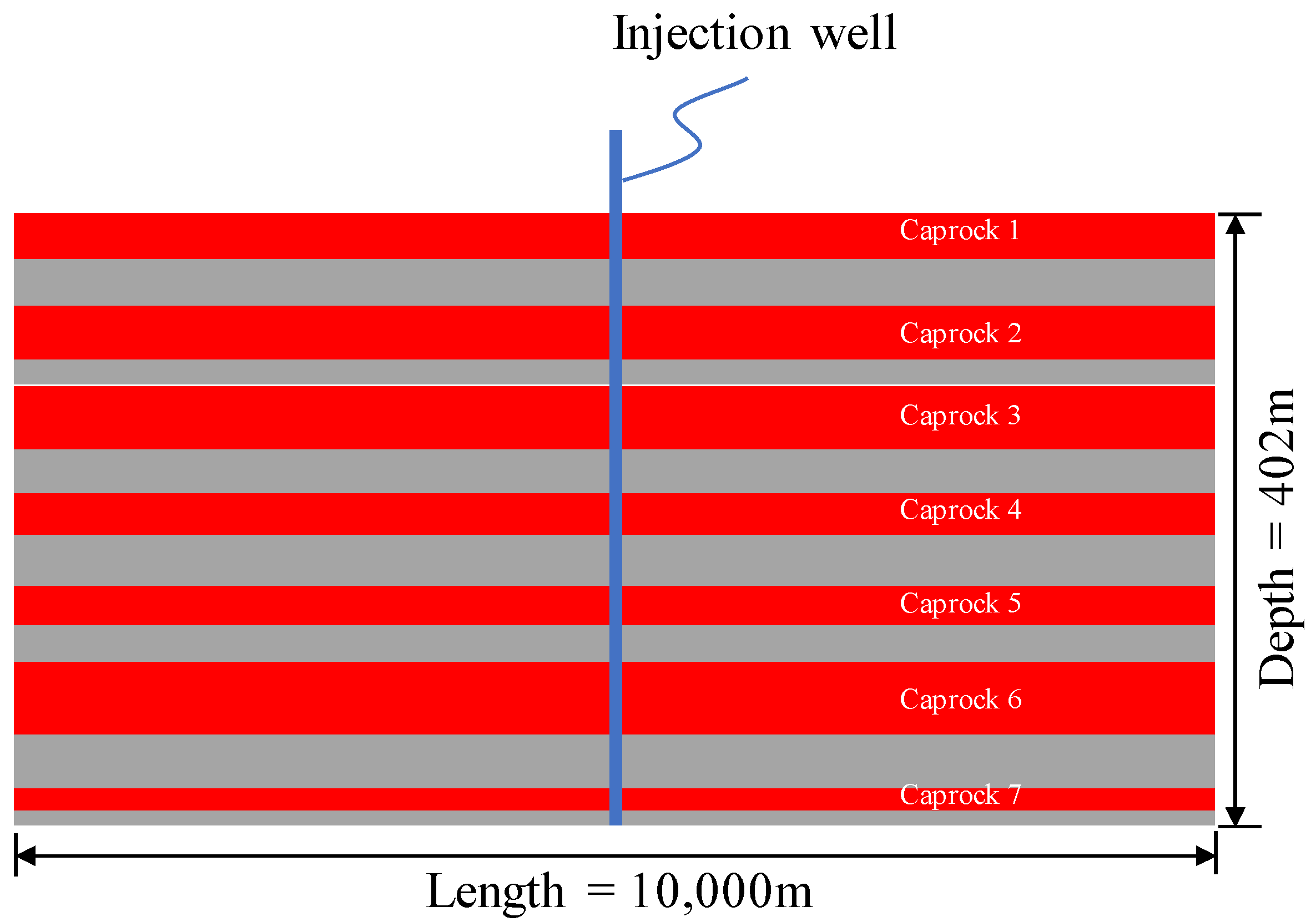
2.1. Location of the CCUS Project

The Huizhou hydrocarbon field, located in the north of the Pearl River Mouth Basin, has an area of approximately 11,000 km2, which provides favorable conditions for the application of the CCUS project. The 3D lithofacies model, which contains sandstone and mudstone interlayers of the reservoir, is shown in Figure 1. This lithology model is constructed based on well logging curves, as well as sandstone and mudstone layer data derived from seismic inversion.
The Enping 15-1 oilfield group, located in the Huizhou hydrocarbon field, was selected as the target area. The caprock is buried at a depth of approximately 1500 m, as shown in Figure 2. Sandstone and mudstone layers are interbedded in the target area; therefore, the multi-layer injection method is employed in this study.

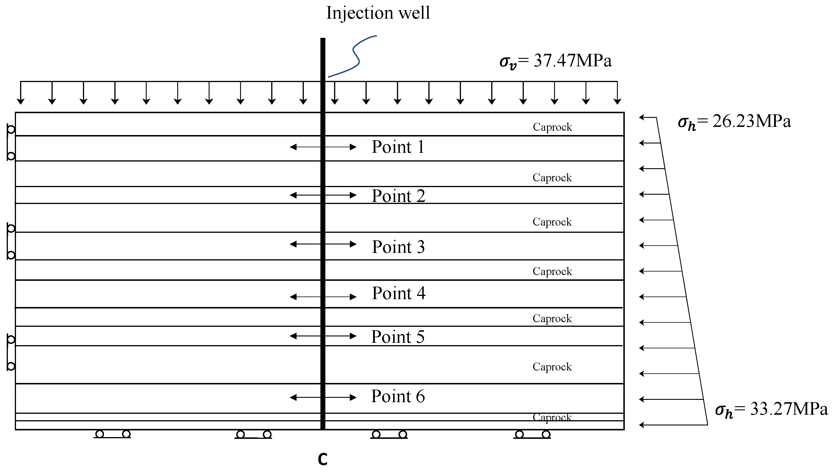
2.2. TOUGH-FLAC Model

TOUGH-FLAC coupling simulation is a numerical approach used to describe the interaction between underground multiphase fluid flow and geomechanical responses [26]. Within this coupling framework, TOUGH calculates multiphase flow, heat conduction, and mass transport in porous media, enabling simulations of subsurface processes such as CO2 injection and thermal energy storage. FLAC, in turn, solves stress-induced deformations and fracture propagation in the formations resulting from fluid injection or pressure variations. The TOUGH-FLAC model has been widely applied in areas such as CO2 geological storage [27], geothermal energy extraction [28], and unconventional oil and gas development [29], offering a robust predictive tool for geotechnical engineering.
Indeed, Thermo–Hydro–Mechanical–Chemical (T–H–M–C) coupling plays a critical role in long-term CO2 geological storage, particularly in assessing the evolution of reservoir properties over decades to centuries. However, this study focuses on the short-term behavior (10 years) of CO2 injection into offshore saline aquifers. During this period, the dominant factor influencing storage integrity is pore pressure. Therefore, we adopted a Hydro–Mechanical (H–M) coupling approach, which captures the essential interactions between fluid flow and rock deformation. This simplification is consistent with other studies that focus on injection-phase assessments [30,31].
The basic assumptions of numerical models are as follows: (1) not considering the impact of chemical reactions generated by CO2 injection on the response of geomechanical response; (2) not considering the impact of pore pressure caused by CO2 injection on porosity of rocks; (3) not considering the thermal stress caused by CO2 injection; (4) the formation is in a fully saturated state before injection and flow follows Darcy’s law.
A two-dimensional multi-layer reservoir and caprock model is established using the TOUGH-FLAC framework for investigating the interaction between mechanical deformations and fluid flows during CO2 injection, as shown in Figure 3.
The model contains six high-permeability reservoirs and six low-permeability caprocks. From top to bottom, the thicknesses of the caprocks are 30, 36, 42, 24, 24, 48, and 12 m, and the thicknesses of the reservoirs are 30, 18, 30, 36, 24, 36, and 12 m.
CO2 is injected into the numerical model using the multi-layer injection method. There are six injection points in the injection well, and these points are located in the middle of the upper six reservoirs at depths of −1543, −1603, −1669, −1729, −1777, and −1855 m. The injection rate is assigned to each layer according to Equation (1).
q i = k i H i i k i H i q
where q is the total flow, qi is the flow of each layer, ki is the permeability of each layer, and Hi is the thickness of each layer. In this research, the target total injection volume of the numerical simulation is 1.0 million tons/year which is equal to 30 kg/s. Equation (1) is used to calculate the injection rate for each layer, and the results are 5.2, 3.1, 5.2, 6.2, 4.1, and 6.2 kg/s, respectively. The reservoirs and the caprocks are considered elastoplastic and described using the Mohr–Coulomb model. The hydrologic and mechanical parameters are shown in Table 1.
The boundary conditions of the numerical model are also shown in Figure 3. The upper boundary is a constant pressure with σv = 37.47 MPa and is calculated from the self-weight of the overlying rock. The left side is set as a fixed displacement boundary. The right side is set as a static water pressure boundary, which increases linearly from top to bottom along the depth, and the top horizontal stress σh is 26.23 MPa, which is 0.7 times the vertical stress σv. The vertical and horizontal displacements of the bottom boundary are both limited to zero.

3. Numerical Simulation Results
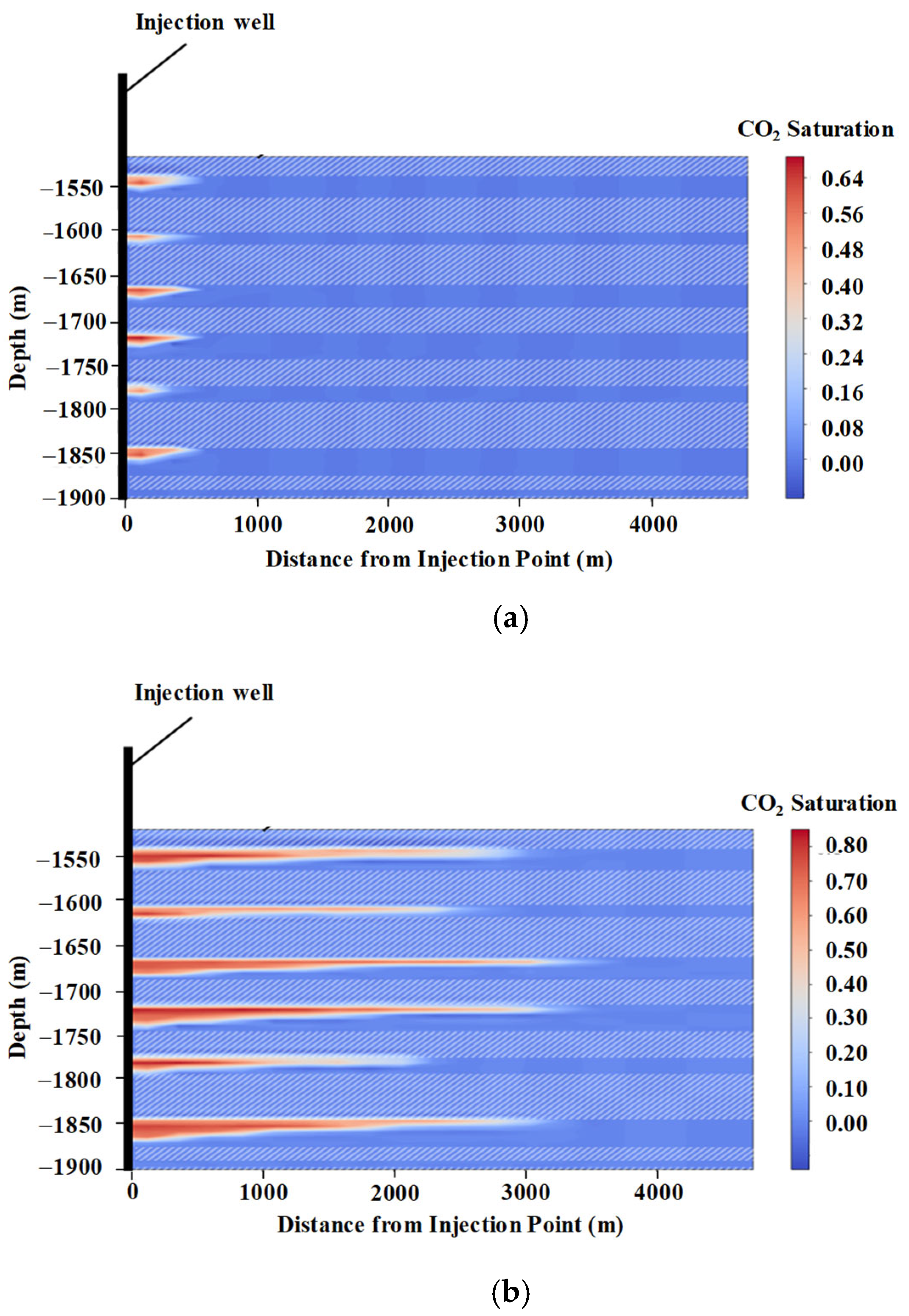
In the early stages of injection, CO2 migrates upwards and accumulates at the bottom of the caprock. When the saturation of accumulated CO2 reaches a certain value, CO2 begins to displace reservoir fluid and diffuse further away, which can cause uplift and deformation of the caprock [32]. If the pore pressure of the reservoir exceeds the rupture pressure of the caprock, the interface between the reservoir and the caprock is subjected to shear or tension, which can easily cause hydraulic rupture of the caprock and generate high permeability channels, leading to CO2 leakage. Therefore, CO2 saturation, pore pressure, and Coulomb failure stress were selected as indices to evaluate the influence of sensitivity parameters on CO2 sequestration capacity in this research.

3.1. CO2 Saturation

Figure 4 shows the distribution of CO2 saturation in the reservoirs after one year and ten years of CO2 injection. It can be observed that the distribution of CO2 in the reservoir roughly presents an inverted triangle shape. This is because the density of the injected CO2 is lower than that of the reservoir fluid. Therefore, CO2 first migrates upward to the bottom of the caprock. When the saturation of accumulated CO2 reaches a certain value, CO2 begins to displace the reservoir fluid and diffuse further along the bottom of the caprock, gradually forming an inverted triangle distribution shape of CO2 in the reservoir.
The values of the horizontal migration distance of CO2 are shown in Table 2. It can be found that after one year of injection, the maximum and minimum CO2 horizontal migration distances are 572.0 and 400.0 m, respectively, with an average migration distance of 531.3 m. After ten years of CO2 injection, the maximum and minimum CO2 horizontal migration distances increase to 3300.0 and 2270.0 m, respectively, with an average migration distance of 2988.8 m, which is 5.6 times that of the first year of injection.
This phenomenon reflects buoyancy-driven CO2 migration and lateral pressure dissipation, which are characteristic of offshore deep saline aquifers. In addition to the overall migration trend, an analysis of individual reservoir layers reveals that Reservoirs 3 and 4 exhibit the greatest CO2 migration distances—3505 m and 3300 m, respectively—during the 10-year injection period, as shown in Table 2. These results suggest that Reservoirs 3 and 4 are the most favorable targets for CO2 storage, and the injection strategies should prioritize them to enhance storage efficiency and safety.

3.2. Pore Pressure

The distribution of reservoir pore pressure increments ΔP after injecting CO2 into the reservoir for one year and ten years is shown in Figure 5 and Table 3.
From the results of Figure 5 and Table 3, it is found that the value of ΔP near the injection point decreases slowly with an increase in injection time. The values of ΔP at Points A and C are 1.3 and 0.91 MPa after one year of CO2 injection, and these values decrease to 1.1 and 0.76 MPa, respectively, after ten years of CO2 injection. This is because at the initial stage of injection, CO2 accumulates at the bottom of the caprock, causing an increase in pore pressure. When the saturation of accumulated CO2 reaches a certain value, CO2 begins to displace reservoir fluid and the pore pressure gradually dissipates. In contrast, the pore pressure far from the injection point continues to increase slowly with the increase in injection time. The values of ΔP at Points B and D which are located at a horizontal distance of 3000 m from the injection point are 0.56 and 0.37 MPa, and these values slightly increase to 0.64 and 0.38 MPa after ten years of CO2 injection.
Figure 5 also shows the stress state at the injection points. After one year of CO2 injection, the average effective stress at Point C in the deep reservoir is 39.5 MPa, which is larger than the 33.0 MPa at Point A in the shallow reservoir. The Mohr circle of Point C is far away from the rock failure line, which means that the deep reservoir is safer than the shallow reservoir. After ten years of CO2 injection, the average effective stress at Point C in the deep reservoir remains unchanged, but the average effective stress at Point A in the shallow reservoir decreases to 32.0 MPa.

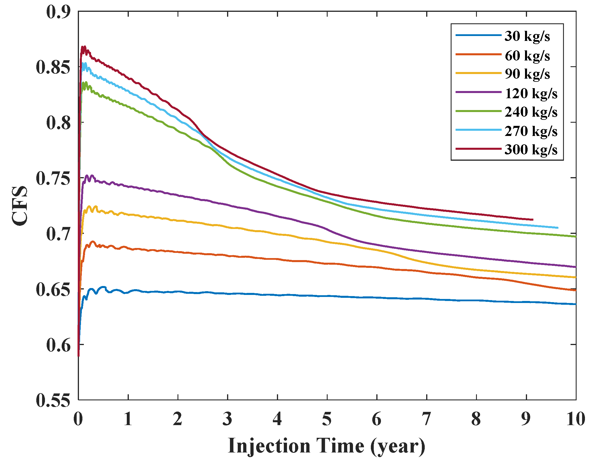
3.3. The Coulomb Failure Stress

In general, a high injection rate can increase the CO2 storage capacity. However, it can also increase the pore pressure in the reservoir, leading to reservoir and caprock fractures and increasing the risk of CO2 leakage. Therefore, it is necessary to determine a reasonable injection rate based on the safety of caprocks and the economy of the reservoirs.
In this research, the Coulomb failure stress (CFS) is selected as the indicator to identify the impact of injection rate on the safety of the caprocks during numerical simulations. The value of the CFS can be calculated from Equation (2).
C F S = τ / ( C + μ ( σ + P ) )
where τ is the magnitude of the shear stress on the plane, σ is the normal stress on the plane, P is the pore pressure, C is the cohesion force, and μ is the friction coefficient. The larger the CFS is, the worse the stability of the caprock. When the value of CFS is greater than or equal to 1, it indicates that the rock stress reaches its failure state.
The maximum CFS values that occur in the reservoirs and the caprocks at different injection rates (30, 60, 90, 120, 240, 270, and 300 kg/s) were monitored. The simulation results are shown in Figure 6. It is found that the CFS value reaches its peak at 0.65 within one year when the injection rate is 30 kg/s. Then, as the injection time increases, the pore pressure gradually dissipates, resulting in a slow decrease in the CFS value. After ten years of injection, the value of CFS decreases by 1.5%. In addition, it is found that under the same conditions, the higher the injection rate, the higher the CFS value. At an injection rate of 300 kg/s, the CFS value peaks at 0.87 within one year. However, as the injection time increases, the CFS value rapidly decreases; the CFS value is 0.72 after ten years of injection, a decrease of 17.2% compared to the peak condition.
Numerical results show that a CO2 injection rate of 30 kg/s, corresponding to an annual injection volume of 1 million tons, results in acceptable increases in pore pressure and CFS values, staying within safe operational thresholds over a 10-year injection period. This indicates that the proposed injection plan is both technically feasible and geomechanically stable under multi-layer injection scenarios.

4. Sensitivity Analysis for Each Site Parameter

Parameters influencing CO2 storage capacity can be categorized into three types, namely, physical parameters, mechanical parameters, and geological parameters. Physical parameters (e.g., permeability, porosity, density) are directly associated with the flow properties of the reservoir rocks, determining the injectivity of CO2. High porosity and permeability enhance CO2 migration and storage, while density influences buoyancy-driven flow dynamics. Mechanical parameters (e.g., Young’s modulus, Poisson’s ratio, friction angle) govern the stress–strain behavior and mechanical integrity of both reservoir and caprock. They are critical in evaluating the risk of shear failure or tensile fracturing under elevated pore pressures during injection. Geological parameters (e.g., depth, thickness of reservoirs and caprocks) affect the initial stress regime through lithostatic loading and constrain the vertical and lateral extent of CO2 migration. Deeper and thicker formations typically provide more confinement and a greater safety buffer for injection.
The influence of reservoir and caprock parameters on caprock stability during the CO2 single-layer injection processes has been investigated by many researchers [33,34,35]. It is found that the depth, thickness, Young’s modulus, permeability, and injection rate of the reservoir have a significant impact on caprock stability. As the seepage–stress coupling mechanism of reservoir and caprock under multi-layer injection is much more complex than that of the single-layer injection, sensitivity analyses were therefore carried out in this research using the tornado analysis method [36,37] to quantify the response of caprock sealing capacity caused by the reservoir and caprock parameters.
In this study, 60%, 80%, 100%, 120%, and 140% of the benchmark parameter values were taken as the values for a single simulation. The geological survey shows that the range of values from 60% to 140% is sufficient to cover the characteristics of rocks. The parameter values for the tornado analysis are shown in Table 4.
Numerical simulations were conducted at different CO2 injection rates to determine the maximum injection capacity that the site can withstand under a specific combination of the physical and mechanical parameters of the reservoir and caprock listed in Table 4. The ratio of the maximum injection capacity of four parameter levels (80%, 100%, 120%, 140%) to the benchmark value (100%) which is 18 million tons/year calculated in Figure 7 is taken as the index to quantify the effect of caprock and reservoir parameters on the maximum injection capacity of CO2. Tornado sensitivity analysis results are shown in Figure 7.
It is found that among the 14 input parameters, the reservoir permeability kr has the greatest impact on the maximum injection capacity of CO2. This result is consistent with the finding by Wei et al. [38]. The values of kr decrease and increase by 40% under the benchmark conditions, resulting in a decrease of 39% and an increase of 25% in the maximum injection capacity, respectively.
The caprock friction angle ϕc and the reservoir friction angle ϕr have a significant impact on the maximum injection capacity. The values of ϕc and ϕr are reduced by 20% under the benchmark conditions, resulting in a decrease of 21% and 19% in the maximum injection capacity, respectively. This is because the friction angle directly enters into the CFS in Equation (2), where the friction coefficient μ = tanϕ. Therefore, both ϕr and ϕr critically control the threshold between safe storage and mechanical failure. This effect is particularly pronounced in offshore settings, where high in situ stresses amplify the mechanical response.
The Poisson’s ratio νr of the reservoir and the Poisson’s ratio νc of the caprock also have a certain impact on the maximum injection capacity. When the value of νr increases by 40%, the maximum injection capacity decreases by 2.5%, whereas when the value of νc increases by 40%, the maximum injection capacity increases by 2%.
On the other hand, the caprock dry density ρc, the caprock void ratio nc, and the reservoir dry density ρr have the smallest impact on the maximum injection capacity. When these three parameters are changed by 80–140% under the benchmark conditions, the change in the maximum injection capacity is less than 1%.
In conclusion, the sensitivity analysis identified the permeability of the reservoirs and the friction angle of the reservoirs and caprocks as critical parameters influencing the storage performance. This finding implies that accurate characterization of these parameters is essential in field applications to ensure caprock integrity and optimized injection design.

5. Conclusions

This study presented a Hydro–Mechanical (H–M) coupled simulation of short-term CO2 geological storage in the Enping 15-1 offshore saline aquifer, China. Numerical simulations using the TOUGH-FLAC model were carried out to estimate pore pressure, CO2 migration, and Coulomb failure stress (CFS) of the reservoir and caprock to assess the mechanical stability and storage performance under various geological and operational conditions using a multi-layer injection method. The main findings are summarized as follows:
  • A total injection rate of 30 kg/s (equivalent to 1 Mt/year), distributed across six reservoir layers, was demonstrated to be geomechanically safe over a 10-year period, with the CFS values remaining below the critical thresholds in saline aquifers.
  • The average CO2 migration distance increased by 5.6 times over the injection period, with Reservoirs 3 and 4 showing the greatest lateral migration distances (3505 m and 3300 m), indicating high storage potential and favorable containment conditions. From an engineering perspective, the results provide practical guidance for offshore CO2 storage site selection and injection planning.
  • Sensitivity analyses showed that the permeability of the reservoirs and the friction angle of the reservoirs and caprocks were the dominant factors influencing mechanical safety and injection efficiency. This finding implies that accurate characterization of these parameters is essential in field applications to ensure caprock integrity and optimized injection design.
It should be noted that the model does not incorporate thermochemical effects and mineralization due to long-term chemical reactions. Moreover, the absence of site-specific field validation introduces uncertainty in the absolute predictions. Future research should aim to develop fully coupled Thermo–Hydro–Mechanical–Chemical (T–H–M–C) models and utilize field monitoring data to calibrate and validate the simulation results. Long-term post-injection migration and trapping mechanisms should also be assessed to support safe and sustainable offshore carbon storage operations.

Author Contributions

Conceptualization, J.S. and Y.H.; methodology, J.S., F.M. and Z.T.; software, F.M. and Z.T.; validation, F.M. and J.S.; formal analysis, J.S., F.M. and Z.T.; investigation, J.S., F.M., and Y.H.; resources, Y.H., T.X. and B.G.; writing—original draft preparation, J.S.; writing—review and editing, J.S., F.M., B.G., T.X. and Y.H.; supervision, Y.H.; project administration, T.X. and Y.H.; funding acquisition, J.S. and Y.H.; All authors have read and agreed to the published version of the manuscript.

Funding

This study was funded by the Donghai Laboratory (DH-2022ZY0007); National Natural Science Foundation of China (42477144, U24A20609).

Data Availability Statement

The data used to support the findings and results of this study are available from the corresponding author upon request.

Conflicts of Interest

Author Bo Gao and Tao Xuan were employed by the company Engineering Technology Branch, CNOOC Energy Development Co., Ltd. The remaining authors declare that the research was conducted in the absence of any commercial or financial relationships that could be construed as a potential conflict of interest.

References

  1. Luo, P.; Zhang, Z.; Zhang, L.; Liu, X.; Liu, X. Influence of different CO2 phase states on fluid flow pathways in coal: Insights from image reconstruction and fractal study. Bull. Eng. Geol. Environ. 2023, 82, 266. [Google Scholar] [CrossRef]
  2. Leng, J.; Bump, A.; Hosseini, S.; Meckel, T.; Wang, Z.; Wang, H. A comprehensive review of efficient capacity estimation for large-scale CO2 geological storage. Gas Sci. Eng. 2024, 126, 205339. [Google Scholar] [CrossRef]
  3. Kumar, S.; Foroozesh, J.; Edlmann, K.; Rezk, M.; Lim, C. A comprehensive review of value-added CO2 sequestration in subsurface saline aquifers. J. Nat. Gas Sci. Eng. 2020, 81, 103437. [Google Scholar] [CrossRef]
  4. Qin, J.; Zhong, Q.; Tang, Y.; Rui, Z.; Qiu, S.; Chen, H. CO2 storage potential assessment of offshore saline aquifers in China. Fuel 2023, 341, 127681. [Google Scholar] [CrossRef]
  5. Calvo, R.; Taragan, R.; Rosenzweig, R. Influence of geostatistical interpolation method and cell-size resolution on CO2 storage capacity estimates: Application to saline aquifers with sparse data availability in Israel. Int. J. Greenh. Gas Control 2022, 130, 104013. [Google Scholar] [CrossRef]
  6. Ye, L.; Liu, Z.; Du, J.; Jia, C.; Zhu, H.; Liu, F. Geological storage test and transport rule of CO2 in saline aquifers: A case study of Dezhou carbon storage demonstration zone in Shandong Province. Fuel 2024, 377, 132752. [Google Scholar] [CrossRef]
  7. Wang, F.; Cao, J.; Zhang, Y.; Aviso, K.; Tan, R.; Li, Z.; Jia, X. Safety risk assessment of the large-scale carbon capture, utilization, and storage demonstration project in Dongying, China. J. Clean. Prod. 2023, 414, 137699. [Google Scholar] [CrossRef]
  8. Marshall, J. A social exploration of the West Australian Gorgon Gas, carbon capture and storage project. Clean Technol. 2016, 86, 371–380. [Google Scholar] [CrossRef]
  9. Chen, B.; Li, Q.; Tan, Y.; Zhang, Y.; Yu, T.; Zhong, Y.; Ma, J.; Li, X. Key indicators of caprock sealing assessment with consideration of faults in potential CO2 geological storage sites in Subei Basin, China. Gas Sci. Eng. 2024, 129, 205414. [Google Scholar] [CrossRef]
  10. Xu, J.; Wan, H.; Wu, Y.; Liu, S.; Yan, B. Study on CO2-Enhanced Oil Recovery and Storage in Near-Depleted Edge–Bottom Water Reservoirs. J. Mar. Sci. Eng. 2024, 12, 2065. [Google Scholar] [CrossRef]
  11. Agada, S.; Kolster, C.; Williams, G.; Vosper, H.; MacDowell, N.; Krevor, S. Sensitivity analysis of the dynamic CO2 storage capacity estimate for the Bunter Sandstone of the UK Southern North Sea. Energy Procedia 2017, 114, 4564–4570. [Google Scholar] [CrossRef]
  12. Li, Q.; Cai, B.; Chen, F.; Liu, G.; Liu, L. Review of environmental risk assessment methods for carbon dioxide geological storage. Environ. Eng. 2019, 37, 13–21. [Google Scholar]
  13. Lu, P.; Hao, Y.; Bai, Y.; Liu, W.; Chen, X.; Zheng, H.; Liu, J.; Chen, Y.; Gao, J. Optimum selection of favorable areas for CO2 geological storage in the Majiagou Formation in the Ordos Basin. Int. J. Greenh. Gas Control 2021, 109, 103360. [Google Scholar] [CrossRef]
  14. Zhong, Y.; Li, Q.; Xu, L.; Wen, Y.; Hou, Y.; Gao, W. Tow-phase flow behavior in CO2 geological storage considering spatial parameter heterogeneity. Greenh. Gases-Sci. Technol. 2023, 14, 11–25. [Google Scholar] [CrossRef]
  15. Liu, H.; Hou, Z.; Were, P.; Gou, Y.; Sun, X. Simulation of CO2 plume movement in multilayered saline formations through multilayer injection technology in the Ordos Basin, China. Environ. Earth Sci. 2014, 45, 216–232. [Google Scholar] [CrossRef]
  16. Li, C.; Zhang, K.; Wang, Y.; Guo, C.; Maggi, F. Experimental and numerical analysis of reservoir performance for geological CO2 storage in the Ordos Basin in China. Int. J. Greenh. Gas Control 2016, 8, 948–966. [Google Scholar]
  17. Zhu, Q.; Zuo, D.; Zhang, S.; Zhang, Y.; Wang, Y.; Wang, L. Simulation of geomechanical responses of reservoirs induced by CO2 multilayer injection in the Shenhua CCUS project, China. Int. J. Greenh. Gas Control 2015, 42, 405–414. [Google Scholar] [CrossRef]
  18. Shi, L.; Bai, B.; Wu, H.; Li, X. Evaluating reservoir risks and their influencing factors during CO2 injection into multilayered reservoirs. Geofluids 2017, 6059142. [Google Scholar] [CrossRef]
  19. Rasmusson, K.; Tsang, C.; Tsang, Y.; Rasmusson, M.; Pan, L.; Fagerlund, F.; Bensabat, J.; Niemi, A. Distribution of injected CO2 in a stratified saline reservoir accounting for coupled wellbore-reservoir flow. Greenh. Gases-Sci. Technol. 2015, 5, 419–436. [Google Scholar] [CrossRef]
  20. Bai, B.; Li, X.; Wu, H.; Wang, Y.; Liu, M. A methodology for designing maximum allowable wellhead pressure for CO2 injection: Application to the Shenhua CCUS demonstration project, China. Greenh. Gases-Sci. Technol. 2017, 7, 158–181. [Google Scholar] [CrossRef]
  21. Ma, J.; Cheng, G.; Li, X. Influencing factors of caprock sealing performance of CO2 multi-formation injection technology. Rock Soil Mech. 2024, 45, 3447–3460. [Google Scholar]
  22. Li, C.; Tien, N.; Zhang, K.; Jen, C.; Hsieh, P.; Huang, S.; Maggi, F. Assessment of large-scale offshore CO2 geological storage in Western Taiwan Basin. Int. J. Greenh. Gas Control 2013, 19, 281–298. [Google Scholar] [CrossRef]
  23. Li, P.; Zhang, Y.; Zhou, D.; Liang, X. Geological characterization and numerical modelling of CO2 storage in an aquifer structure offshore Guangdong Province, China. Energy Procedia 2018, 154, 48–53. [Google Scholar] [CrossRef]
  24. Tang, W.; Xie, X.; Wang, Y.; Xiong, L.; Guo, J.; Li, X. Evolution of Cenozoic sedimentary architecture in Central and Southern South China Sea basins. J. Palaeogeogr. 2024, 13, 35–53. [Google Scholar] [CrossRef]
  25. Izadpanahi, A.; Blunt, M.; Kumar, N.; Ali, M.; Tassinari, C.; Sampaio, M. A review of carbon storage in saline aquifers: Mechanisms, prerequisites, and key considerations. Fuel 2024, 369, 131744. [Google Scholar] [CrossRef]
  26. Rutqvist, J.; Tsang, C.F. A study of caprock hydromechanical changes associated with CO2-injection into a brine formation. Environ. Geol. 2002, 42, 296–305. [Google Scholar] [CrossRef]
  27. Kim, T.; Park, C.; Watanabe, N.; Park, E.; Park, J.; Jung, Y.; Kolditz, O. Numerical modeling of two-phase flow in deformable porous media: Application to CO2 injection analysis in the Otway Basin, Australia. Liquids 2021, 80, 121. [Google Scholar] [CrossRef]
  28. Basmanov, O.; Kiryukhin, A.; Maguskin, M.; Dvigalo, V.; Rutqvist, J. Thermo-hydrogeomechanical modeling of vertical ground deformation during the operation of the Mutnovskii Geothermal Field. J. Volcanol. Seismol. 2016, 10, 138–149. [Google Scholar] [CrossRef]
  29. Qi, L.; Zhang, Y. Numerical simulation analysis of parameters in an artificial gas cap of CO2 enhanced oil recovery and storage. Chem. Technol. Fuels Oils 2025, 61, 258–267. [Google Scholar] [CrossRef]
  30. Jiang, X. A review of physical modelling and numerical simulation of long-term geological storage of CO2. Appl. Energy 2011, 88, 3557–3566. [Google Scholar] [CrossRef]
  31. Lin, K.; Wei, N.; Zhang, Y.; Liu, S.; Ali, M.; Wang, W.; Chen, Q.; Wang, Y. Hydro-mechanical interactions in CO2 storage: Critical parameters influencing coal mine at Shenhua’s CCUS site. Eng. Geol. 2025, 352, 108087. [Google Scholar] [CrossRef]
  32. Kim, Y.-H.; Park, Y.-G. A Review of CO2 Plume Dispersion Modeling for Application to Offshore Carbon Capture and Storage. J. Mar. Sci. Eng. 2024, 12, 38. [Google Scholar] [CrossRef]
  33. Cheng, Q.; Tang, J.; Liu, Y.; Jia, Y.; Lu, Y.; Sun, X.; Zhao, G.; Liu, Y. Pore alteration of Yanchang shale after CO2-brine-rock interaction: Influence on the integrity of caprock in CO2 geological sequestration. Fuel 2024, 363, 130952. [Google Scholar] [CrossRef]
  34. Petersen, H.; Springer, N.; Weibel, R.; Schovsbo, N. Sealing capability of the Eocene MioceneHorda and Lark formations of the Nini West depleted oil field implications for safe CO2 storage in the North Sea. Int. J. Greenh. Gas Control 2022, 118, 103675. [Google Scholar] [CrossRef]
  35. Li, C.; Laloui, L. Impact of material properties on caprock stability in CO2 geological storage. Geomech. Energy Environ. 2017, 11, 28–41. [Google Scholar] [CrossRef]
  36. Chen, B.; Li, Q.; Tan, Y.; Zhang, Y.; Yu, T.; Ma, J.; Zhong, Y.; Li, X. Caprock sealing integrity and key indicators of CO2 geological storage considering the effect of hydraulic-mechanical coupling: X field in the Bohai Bay Basin, China. Eng. Geol. 2024, 342, 107741. [Google Scholar] [CrossRef]
  37. Lan, Z.; Gong, B. Uncertainty analysis of key factors affecting fracture height based on box-behnken method. Eng. Fract. Mech. 2020, 228, 106902. [Google Scholar] [CrossRef]
  38. Wei, X.; Li, Q.; Li, X.; Sun, Y. Impact indicators for caprock integrity and induced seismicity in CO2 geosequestration: Insights from uncertainty analyses. Nat. Hazards 2016, 81, 1–21. [Google Scholar] [CrossRef]
Figure 1. The 3D lithofacies model of the Huizhou hydrocarbon fields.
Jmse 13 01247 g001
Figure 2. Numerical model of the multi-layer reservoirs.
Jmse 13 01247 g002
Figure 3. Boundary conditions used in the numerical model.
Jmse 13 01247 g003
Figure 4. CO2 saturation and migration distance in the reservoir. (a) 1 year; (b) 10 years.
Jmse 13 01247 g004
Figure 5. Increment of pore pressure in the reservoir. (a) 1 year; (b) 10 years.
Jmse 13 01247 g005
Figure 6. CFS values of the caprock surface under different injection rates.
Jmse 13 01247 g006
Figure 7. The relative change in the maximum injection capacity using tornado analysis.
Jmse 13 01247 g007
Table 1. Parameters of the caprock and the reservoir used in the numerical model.
IndicatorsParametersValuesUnits
Caprock
Young’s modulusEc8GPa
Poisson’s ratioνc0.3-
Permeabilitykc1 × 10−17m2
Void rationc0.01-
Angle of frictionφc30°
Dry densityρc2550kg/m3
Reservoir
Young’s modulusEr8GPa
Poisson’s ratioνr0.3-
Permeabilitykr5 × 10−13m2
Void rationr0.24-
Angle of frictionφr30°
Dry densityρr2550kg/m3
Table 2. Horizontal migration distance of CO2 in the reservoir.
Number of ReservoirInjection Rate, kg/sThickness of Reservoir, mHorizontal Migration Distance, m
1 Year10 Years
15.5305723008
23.1185002650
35.2305723505
46.2365723300
54.1244002270
66.2365723200
Table 3. Increase in pore pressure and average effective stress in the reservoir.
LocationIncrease in Pore Pressure, MPaEffective Stress, MPa
1 Year10 Years1 Year10 Years
A1.31.133.032.0
B0.560.6432.832.5
C0.910.7639.539.5
D0.370.3839.539.5
Table 4. Ranges of input parameters used in the tornado analysis.
Indicators 60%80%100%120%140%
Depth, mZ898.81198.414981797.62097.2
Top caprock thickness, mH1824303642
Caprock
Young modulus, GPaEc4.86.48.09.611.2
Poisson’s ratioνc0.180.240.30.360.42
Permeability,
10−17 m2
kc0.60.81.001.201.40
Void rationc0.0060.0080.010.0120.014
Angle of friction, °φc1824303642
Dry density, kg/m3ρc15302040255030603570
Reservoir
Young modulus, GPaEr4.86.48.09.611.2
Poisson’s ratioνr0.180.240.30.360.42
Permeability,
10−13 m2
kr3.004.005.006.007.00
Void rationr0.1440.1920.240.2880.336
Angle of friction, °φr1824303642
Dry density, kg/m3ρr15302040255030603570
Disclaimer/Publisher’s Note: The statements, opinions and data contained in all publications are solely those of the individual author(s) and contributor(s) and not of MDPI and/or the editor(s). MDPI and/or the editor(s) disclaim responsibility for any injury to people or property resulting from any ideas, methods, instructions or products referred to in the content.

