Article

Lateral Performance of Monopile Foundations for Offshore Wind Turbines in Clay Soils: A Finite Element Investigation

by
Yazeed A. Alsharedah
Department of Civil Engineering, College of Engineering, Qassim University, Buraydah 52541, Qassim, Saudi Arabia
J. Mar. Sci. Eng. 2025, 13(7), 1222; https://doi.org/10.3390/jmse13071222
Submission received: 13 May 2025 / Revised: 5 June 2025 / Accepted: 15 June 2025 / Published: 25 June 2025
(This article belongs to the Special Issue Offshore Renewable Energy, Second Edition)

Abstract

The continued upscaling of offshore wind turbines (OWTs) necessitates the development of foundation systems capable of sustaining increased lateral loads. As monopiles remain the most widely used foundation type for OWTs, a detailed investigation into their lateral behavior and soil flow under operational loading is warranted. This study utilized a nonlinear three-dimensional finite element model (FEM) to assess the lateral performance of monopiles supporting a 5 MW turbine in clayey soils. The results revealed that the lateral capacity and deformation behavior are governed primarily by soil shear strength and the monopile’s length-to-diameter ratio (L/D). In softer soils, increasing the L/D ratio led to notable enhancements in lateral resistance, up to fivefold, as well as significant reductions in pile head displacement and rotation. In contrasts, monopiles in stiff clay exhibited distinct failure patterns and less sensitivity to L/D variations. Soil deformation patterns at the ultimate state varied depending on stiffness, indicating distinct failure mechanisms in soft and stiff clays. These findings highlight the importance of incorporating realistic soil behavior and geometric influences in monopile foundation design for large OWTs.

1. Preface

The transition to renewable energy continues to be a global priority, with offshore wind energy playing a growing role in reducing reliance on fossil fuels. Advances in turbine technology have led to offshore wind turbines (OWTs) with capacities exceeding 21 MW, necessitating more robust support structures [1]. Among the various foundation types, monopiles remain dominant due to their installation efficiency and established performance in marine environments [2,3]. Figure 1 presents the key statistics and wind energy trends in different European countries in the year of 2024 [4].
Monopile foundations, however, must evolve to accommodate larger turbines and increasing water depths. As foundation systems can represent up to 40% of total project costs, optimizing their design is both economically and structurally critical. Traditional design methods for monopiles under lateral loading include analytical methods such as Brom’s method [5], beam of Winkler foundation (BWF) [6,7,8,9], the API p–y curve approach (Beam on nonlinear Foundation, BNLWF) by [10] and finite element methods such as [11,12] have been widely applied to slender piles. However, these formulations were developed under assumptions that may not hold for the large-diameter monopiles used in OWTs, as the mode of deflection and rotations and the soil response can be fundamentally different [13,14,15,16,17,18,19].
Challenges in applying conventional p–y curves to large-diameter monopiles with low L/D ratios include inaccurate stiffness predictions and failure to account for diameter effects, base shear, side resistance, and cyclic loading behavior. Recent efforts including field tests such as the PISA project [13,20,21] laboratory studies by [22,23,24,25,26,27,28,29] and finite element analyses by [30,31,32,33,34] have introduced improved formulations and emphasized the need for more representative models. These works highlight the importance of side and base shear, installation effects, and reconsolidation in predicting monopile behavior.
To address the current design limitations, this study employed advanced three-dimensional finite element modeling to examine monopile behavior under lateral loading in cohesive soils. A series of simulations was conducted for a 5 MW wind turbine supported by monopiles of varying embedded lengths, tested across a range of soft to stiff clay profiles. The primary goal was to assess the impacts of soil stiffness and L/D ratio on lateral capacity, soil displacement patterns, and failure mechanisms, providing insights to improve the reliability and efficiency of monopile design for future offshore wind developments.

2. Scope of Work

This study investigates the soil structure interactions of monopile foundations supporting a 5 MW offshore wind turbine (OWT) in clayey sediments using a parametric finite element (FE) modeling approach. The goal is to evaluate how changes in pile slenderness (length-to-diameter ratio (L/D)) and soil strength (Su) influence the soil displacement behavior, bending moment profiles, and failure mechanisms.
A total of 42 simulations were conducted in PLAXIS 3D using a non-linear hardening soil model (Hs), with pile embedment lengths ranging from 20 m to 80 m, all with a fixed pile diameter of 6 m (L/D from 3.33 to 13.33), Table 1. Figure 2 presents the geometric notations of the monopile. A lateral load was applied at 40.1 m above the mudline (i.e., 6.83*D) to replicate realistic turbine-induced overturning moments and shear forces. Six representative clay profiles were modelled (Su1 to Su6), encompassing a range from very soft (such as those at the Gulf of Mexico (N.C)) to very stiff cohesive soils (such as those at the North Sea (O.C clays)). A structured and systematic approach was adopted in constructing these profiles, ensuring that the values of Su, Eoed/50/ur, ko, and OCR were interrelated and consistent, Figure 3.

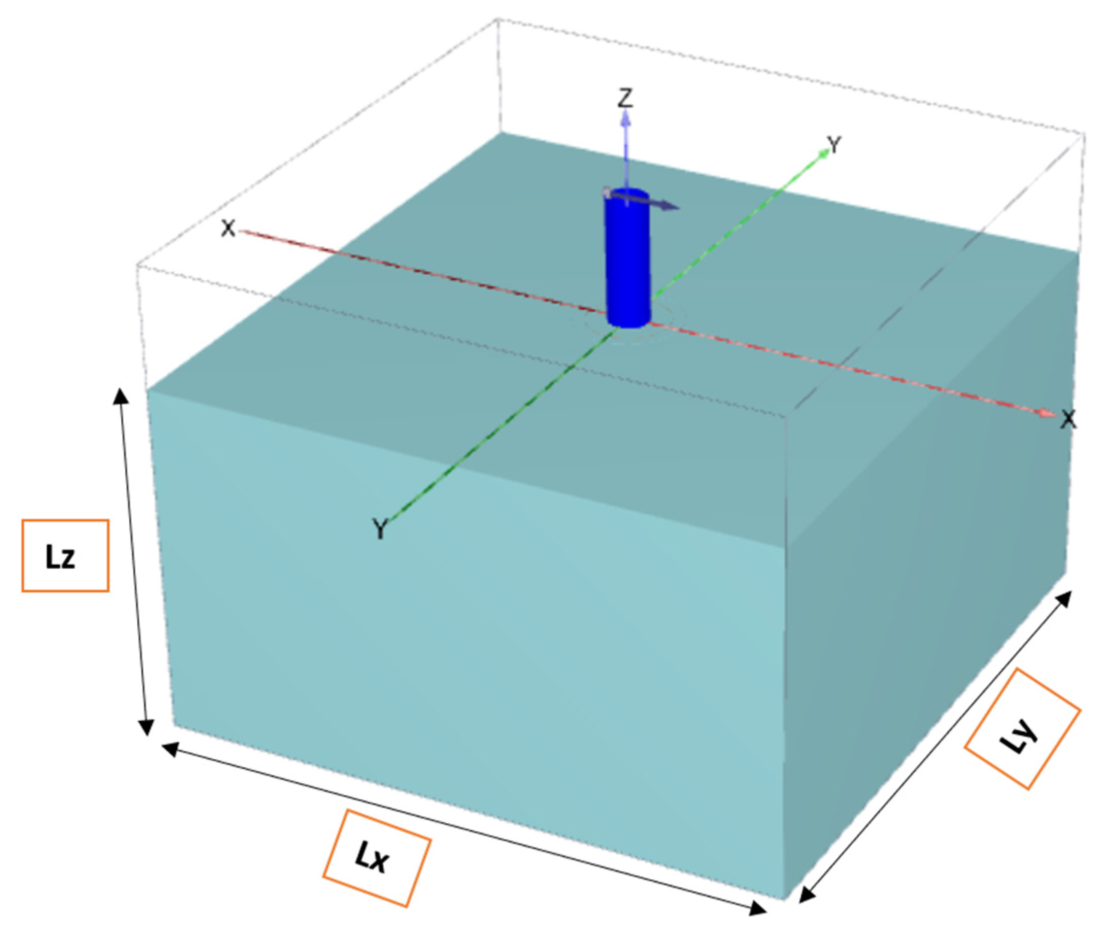
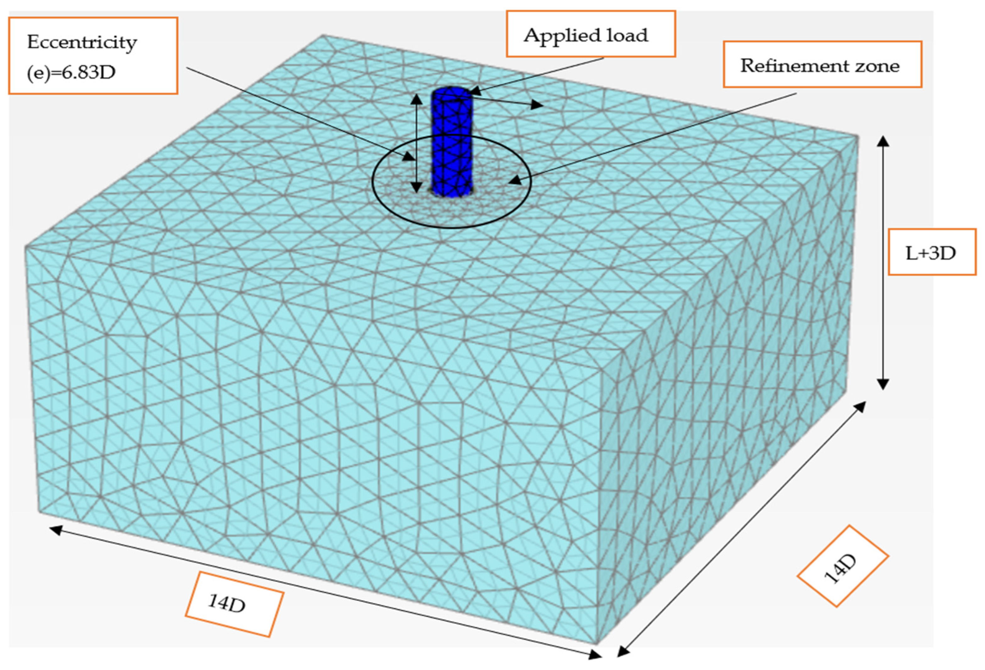
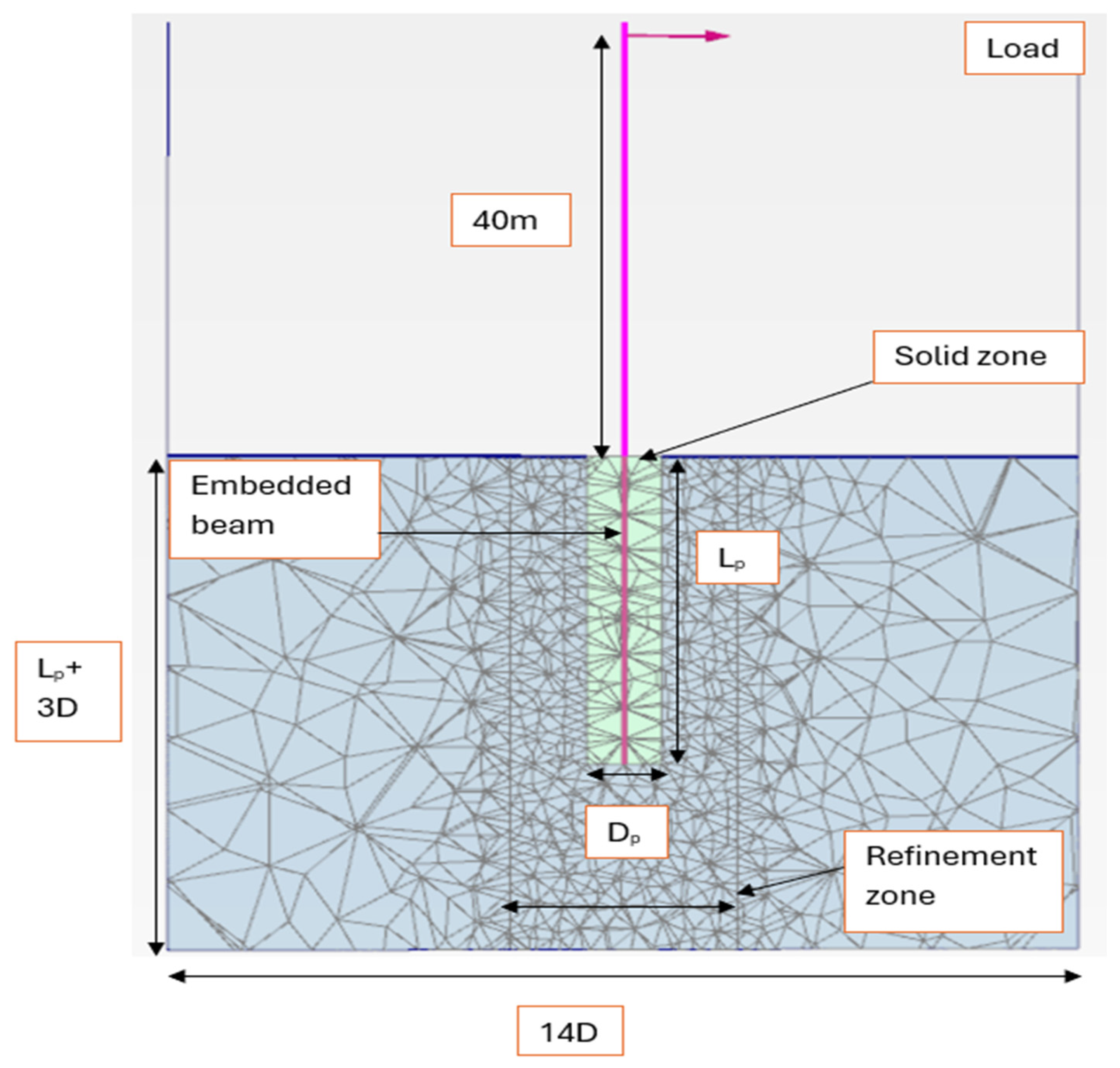
2.1. Finite Element Modeling

A 3D finite element framework was adopted to simulate the lateral response of monopiles embedded in clay. The pile and tower were modeled using embedded beam elements while soil behavior was represented by 10-noded tetrahedral elements. The embedded beam formulation allowed for accurate assessment of flexural performance without explicitly modeling the pile volume. A solid zone surrounding the pile was introduced to approximate open-ended pile behavior, following the recommendations of [13].
To reflect realistic pile flexibility, the Young’s modulus of the pile was reduced by a factor of 10⁶ during modeling, and bending moments were scaled accordingly. Structural failure was defined by exceeding a flexural capacity of 665,000 kN·m while geotechnical failure was determined from load–displacement trends [35].
The hardening soil (HS) model governed the soil response, incorporating non-linear stiffness and stress-dependent parameters [36]. Soil stiffness moduli (E50, Eoed, and Eur) were depth-dependent and linked to the reference pressure using exponential relationships. Interface elements were included at the pile–soil boundary, with a reduction factor (Rint) applied to simulate realistic frictional behavior (Rint = 1.0 for soft clays and 0.3 for stiff clays [37].

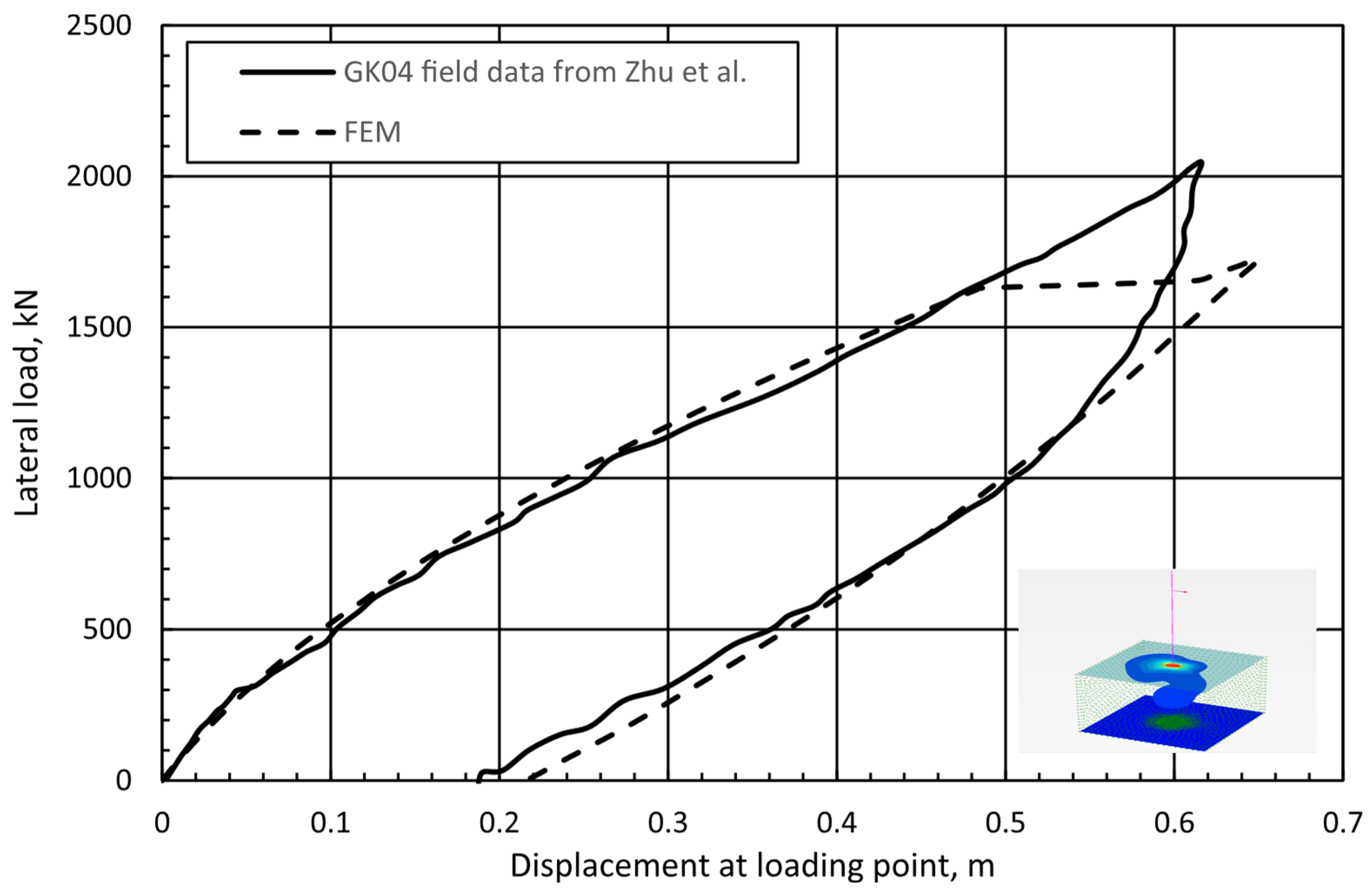
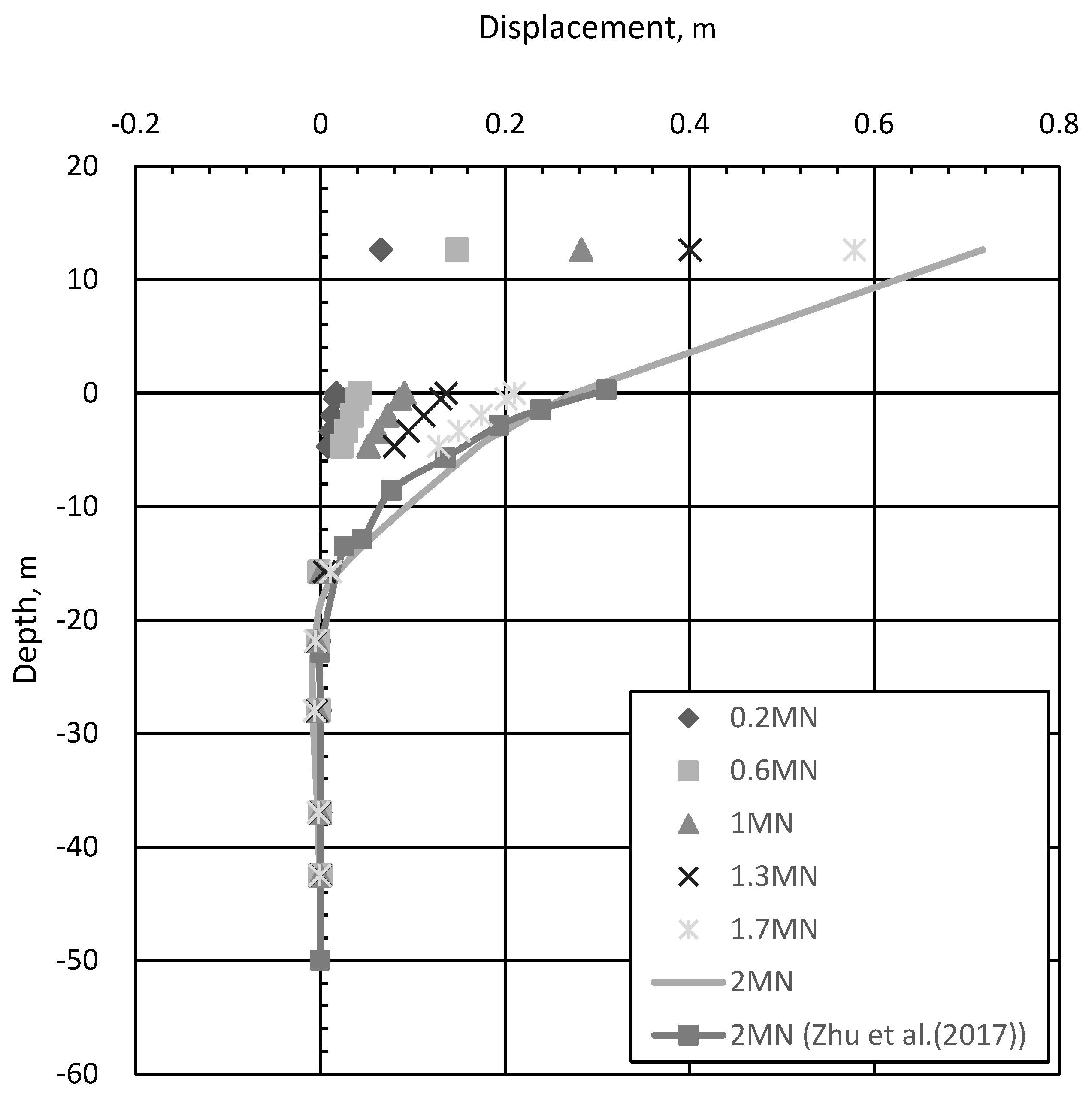
2.1.1. Validation of FE Model

The finite element model was validated against field data from [8], involving a driven steel pile with a diameter of 2.2 m (7.2 ft) and an embedded depth of approximately 57 m (187 ft) in soft clay seabed conditions. Soil parameters were derived from cone penetration test (CPT) results and verified using isotopically consolidated undrained triaxial (CIUC) tests.
The undrained shear strength, Su, was estimated based on the following empirical correlation with cone tip resistance, qc:
Su = 0.07qc + 2 (kPa)
The field-derived Su profile aligned closely with laboratory measurements, confirming the formula’s validity. The small-strain shear modulus Go was derived from both field and calibration data, enabling accurate stiffness modeling. The coefficient of earth pressure at rest, ko, was estimated using Jaky’s empirical formula, and an iterative approach was used to back-calculate the friction angle ϕ′ to produce a similar profile as that from the field CPT data based on Hs model as in Equation (2) [15].
Figure 4 and Figure 5 illustrate the matching profiles of Su, OCR, and Go from field tests and numerical calibration based on Equations (2) and (3) while Table 2 displays the soil physical parameters estimated from the SCPT sounding and the model calibration process.
S u = ( c c o t ( ϕ ) σ 3 ) 2 s i n ( ϕ ) 1 s i n ( ϕ ) 2
Go = G o , ref   ( c c o s ϕ σ 3 s i n ϕ c c o s ϕ + p r e f s i n ϕ ) m

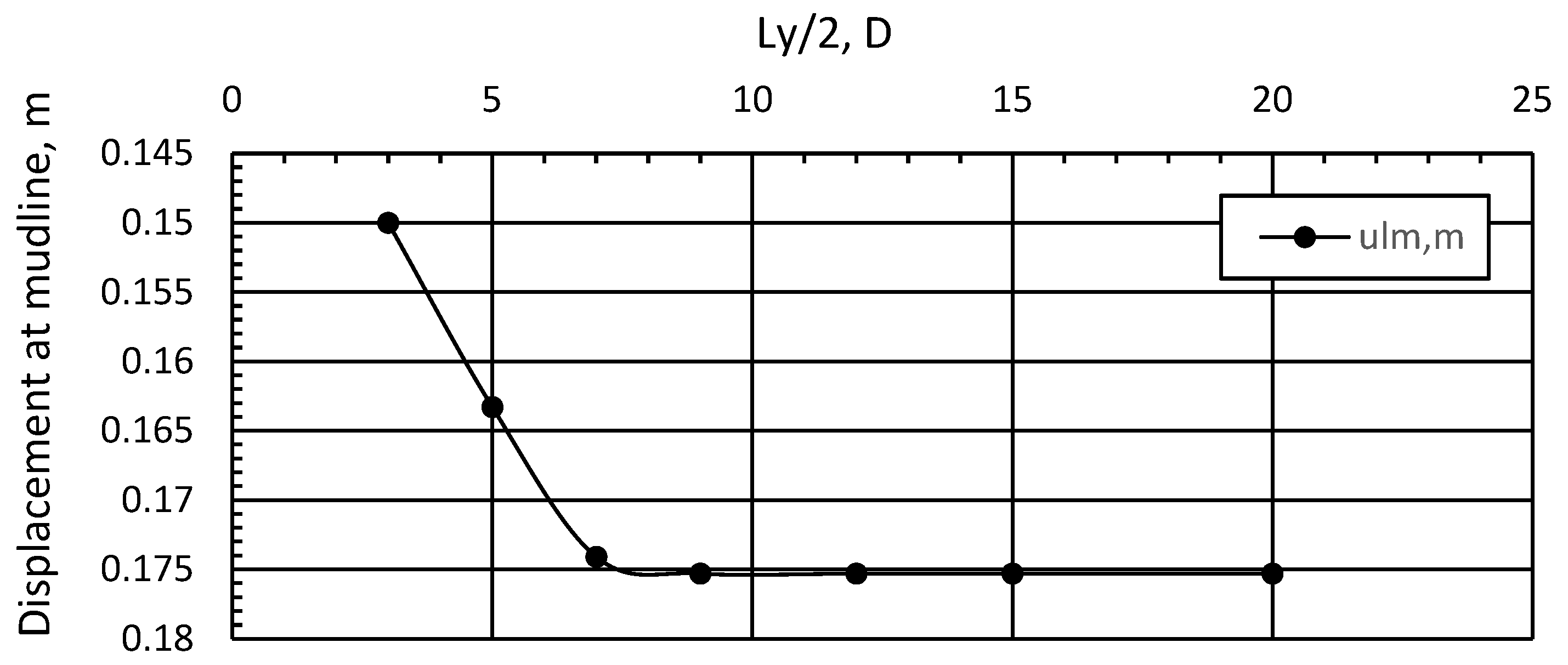
2.1.2. Sensitivity Analysis of Mesh and Boundary Effects
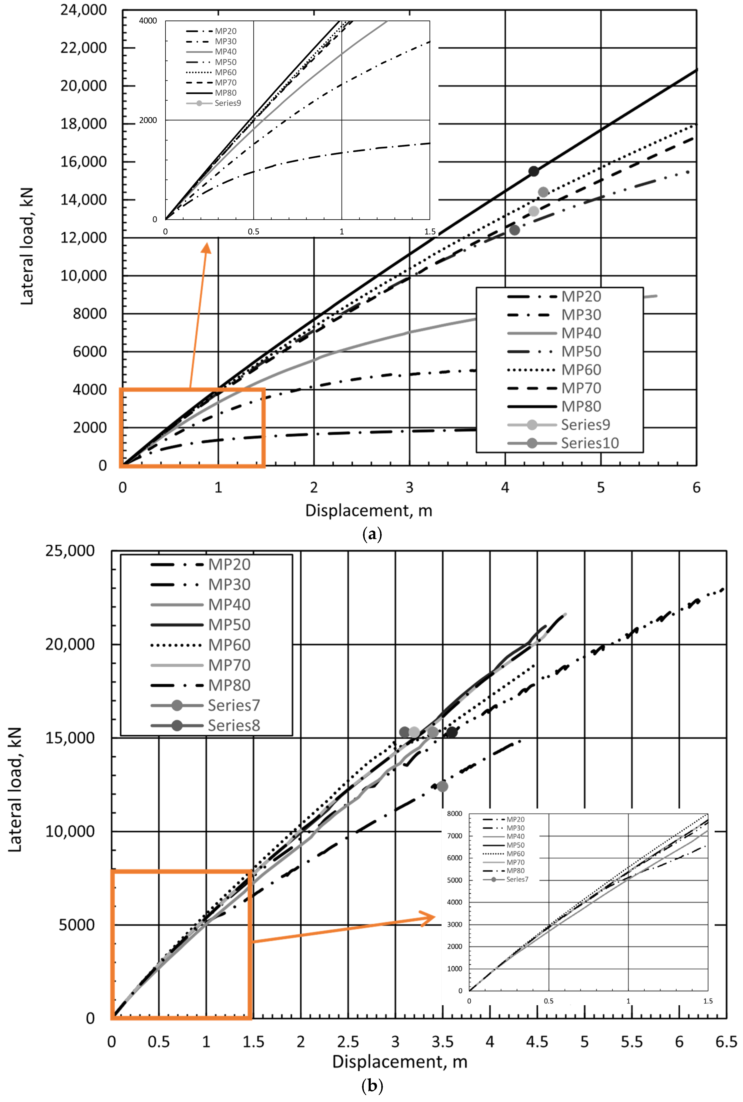
A sensitivity analysis was conducted to evaluate the influence of the model boundary limits and mesh density on the numerical results. The study assessed various domain dimensions (particularly Lz, Lx, and Ly in Figure 6) and refinement zones (Figure 7) to ensure model efficiency without sacrificing accuracy. In all FE analyses, a medium global element size was used, with refinement zones of 3D, 5D, and 7D applied around the monopile, featuring a variable coarseness factor, cf (Figure 8 and Figure 9). Over 100 runs were carried out fixing one parameter and varying the others to obtain the optimal response. In addition to medium-grade meshes, fine-grid simulations were also conducted within the 3D, 5D, and 7D refinement zones by decreasing the global coarseness factor and reducing local element size in the pile–soil interaction region. Comparison of displacement and moment outcomes between fine and medium mesh configurations showed deviations below 4%, justifying the selection of a medium refinement zone with a 3D radius as an optimal solution. For brevity, a one sample analysis of the sensitivity calculations for the case of Ly is displayed in Figure 8 for illustration (7 runs). The optimal scenario was achieved with the refinement zone diameter set to three diameters from the model centerline (Figure 8), Appendix A also shows the full results of a sample scenario.
The optimal configuration used a refinement radius of 3D (three times the pile diameter) around the monopile, resulting in a mesh with 20,000–25,000 elements.
Based on the sensitivity analysis, boundaries were extended 14D in both the x and y directions, with a refinement volume of three monopile diameters around the centerline, resulting in a denser mesh around the zone of influence. Vertical boundaries along the z-axis were restricted horizontally but allowed vertical movement while the bottom boundary was fixed in all directions. This approach aligns with the methodology outlined by [11].
The final mesh configuration and boundary setup are shown in Figure 7 and Figure 9. Vertical boundaries were constrained horizontally but allowed vertical movement while the bottom boundary was fully fixed. These settings ensured accurate deformation and load transfer without artificial boundary influence.
The load–displacement response obtained from the finite element (FE) analysis is showcased in Figure 10, along with the corresponding data from [8] The figure illustrates a notable agreement between the predicted and measured curves, confirming the proficiency of the established finite element model in accurately replicating the behavior of large-diameter piles installed in cohesive soils. Additionally, the comparison of bending moment and inclinometer data in Figure 11 further highlights an excellent correspondence between the model estimates and observed measurements.

3. Results

To determine the lateral ultimate capacity of monopiles, load–displacement responses were analyzed for various pile lengths across soft and stiff clay profiles. Failure was defined by structural yielding or geotechnical instability, with ultimate capacity estimated as the average of the last two stable load points prior to failure.
The monopile SSI behavior—particularly concerning the soil flow around the monopile—pivot point location, and bending moments were assessed at lateral ultimate capacities. As shown in Figure 12, increasing the pile length (i.e., higher L/D ratios) led to significantly stiffer responses and increased lateral capacity in soft clays (Su1). For these soils, even modest increases in embedment depth produced substantial improvements in stiffness and resistance.
In contrast, the monopiles in stiff clays (Su6) exhibited less variation in stiffness and strength with increasing L/D ratio. This indicates that beyond a certain depth, additional embedment offers diminishing returns in terms of lateral resistance. Figure 13 illustrates these behavioral trends and the incremental displacements at failure stage.
It is important to note that, due to elastic modeling of pile elements, load–displacement curves were truncated once flexural capacity was reached. This ensured that the results remained within realistic structural limits. These truncations were observed across both soil types but were more prominent in stiff clay, where moments reached critical values more quickly.

4. Discussion

This section presents the results of the FE modelling program, the behavior of the pile’s conditions, and the flow conditions observed along with relevant structural observation being discussed and highlighted.

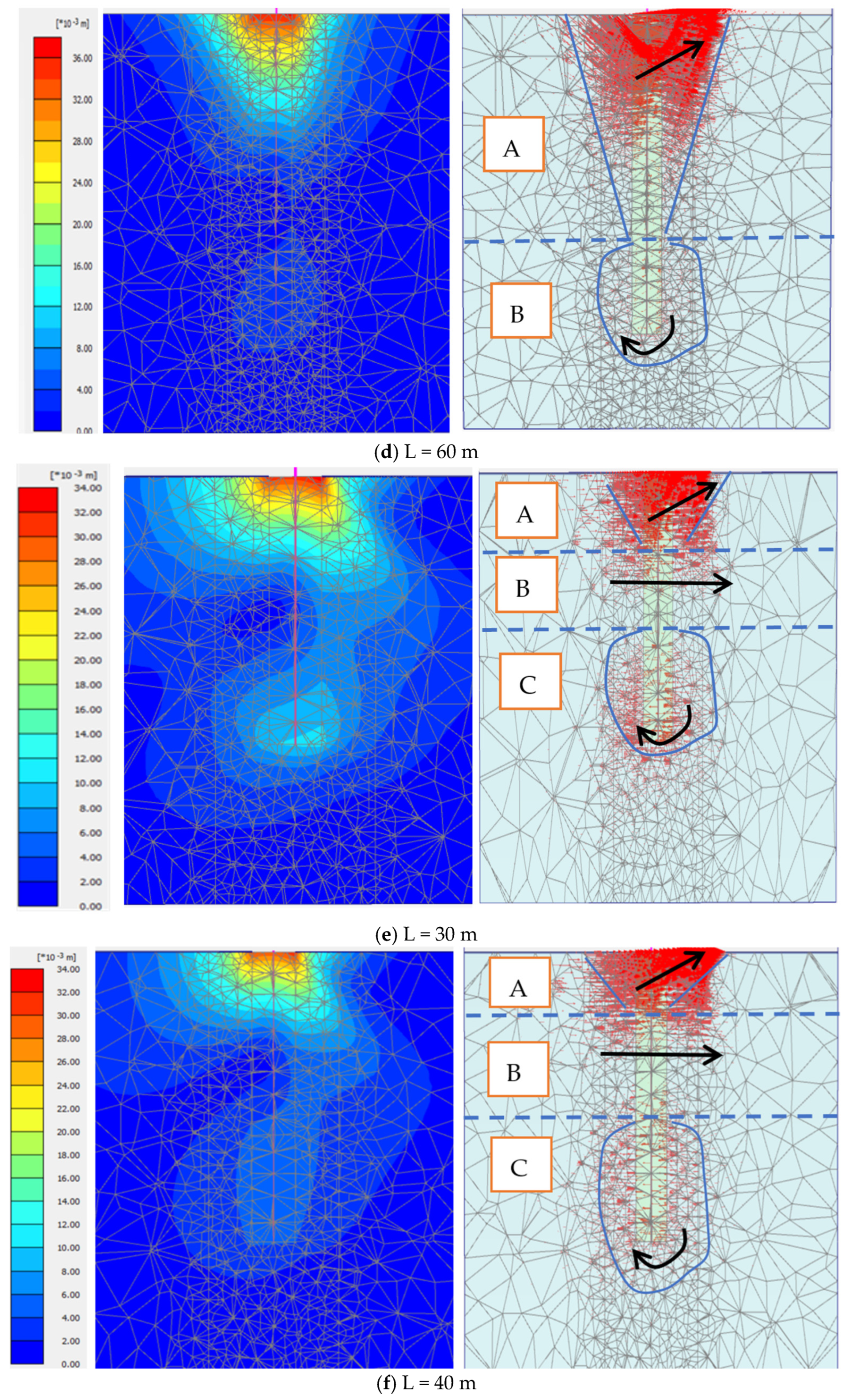
4.1. Behavior at Lateral Ultimate Capacity

Figure 13 illustrates the soil displacement fields at ultimate load levels for various monopile lengths and soil types. In soft clay (su1), the failure mechanism comprised two primary zones:
  • Zone A: a shallow wedge-type failure near the pile head, representing soil movement in a triangular fashion;
  • Zone B: a deeper rotational zone beneath the pile tip, resembling spherical flow patterns.
These zones reflect a rigid pile response, where significant soil mass contributes to resistance. [17] defined upper and lower bound values of EpIp/EsL4 for flexible and rigid piles as 0.0025 and 0.208, respectively. As L/D increased, both the depth and extent of Zone B expanded, enhancing capacity. The depth of Zone A ranges between 0.7 and 0.75 of the pile length whereas the remaining portion of the soil surrounding the pile experiences the rotational movements.
In stiff clay (su6), the displacement fields revealed a more complex failure mechanism for shorter monopiles (L/D ≤ 6.67), including three identifiable regions:
  • Zone A: shallow wedge failure;
  • Zone B: a lateral soil movement region;
  • Zone C: localized rotation beneath the pile tip.
For higher L/D ratios (≥8), the influence of Zone C diminished, and deformation localized near the upper half of the pile. This indicates a shift toward more flexible pile behavior, reducing overall soil mobilization. In the smaller L/D ratios (below 8), the depth of zone A was around 0.25 L while zone B where lateral confined flow happened was observed at lengths from 0.25 to 0.5 L. The remaining pile length experienced flow rotation (Zone C). For larger L/D ratios, Zone C disappeared due to localized failure conditions (long or flexible pile) in the pile material hence smaller soil mass contribution was observed. In this case, Zone A covered the upper 0.25 L, and the lateral flow region (Zone B) was observed until 0.5–0.6 L where the failure took place.

4.2. Max Flexural Moment at Ultimate State

Flexural moment profiles offer further insight into soil–structure interactions. In soft clay, the moment distribution along the pile depth exhibited a rigid response, with negligible negative moments. As L/D increased, bending moments shifted deeper, indicating an extended zone of load transfer.
In stiff clay, shorter piles displayed notable negative moments below the pivot point, indicating partial fixity and transition toward a flexible regime. This change in moment curvature confirms that higher stiffness soils promote pile behavior that differs significantly from soft clay conditions.
It should be noted that the bending moment distributions shown in Figure 14 and Figure 15 are derived from different applied lateral loads, each corresponding to the pile’s ultimate capacity. While this does not permit direct comparison of absolute moment magnitudes across cases, the plots effectively demonstrate how the location and shape of the moment profiles shift with pile length and soil stiffness.

4.3. Effects of Soil Strength on Monopile Performance

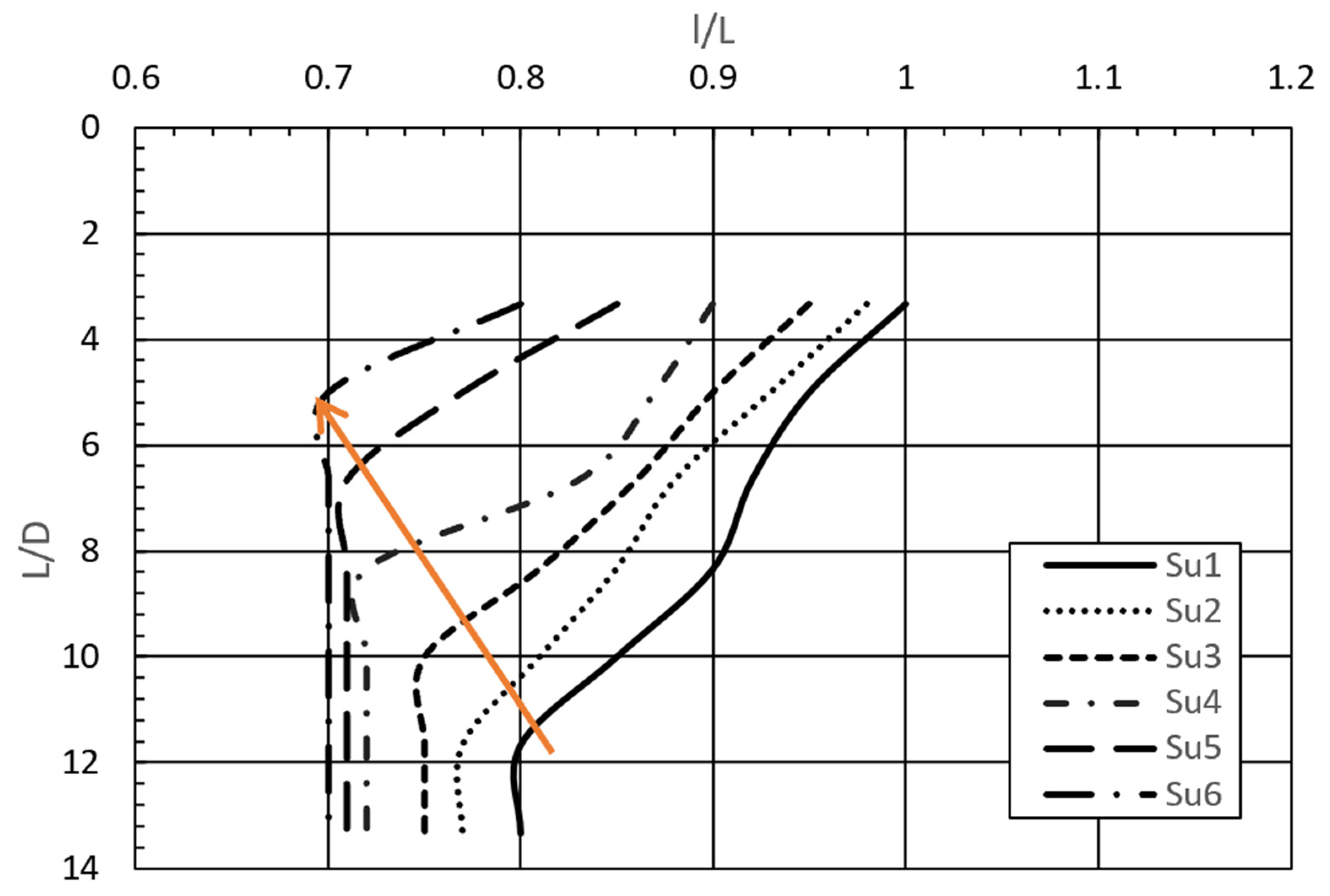
4.3.1. Pivot Point Location

Pile rotation around a neutral axis—the pivot point—is influenced by soil stiffness. Figure 16 presents a comparison of the pile’s pivot point depth (l) as a function of the pile’s length (l/L) at ultimate capacity condition for all piles considered herein versus the L/D ratio. In Figure 16, the normalized pivot depth was tracked and compared across profiles. In softer soils, increasing L/D ratio shifted the pivot point deeper (around 70% of pile’s length), correlating with more substantial soil mobilization. In stiffer clays, pivot movement was minimal beyond a certain pile length, indicating that soil confinement dominated the system response (Figure 16). The added arrow explains this trend of decreasing pivot point depth with increasing shoil shear strength (and decreased relative pile/soil rigidity). For practical considerations, it is suggested to use L/D ratios of above 10 to enhance the geotechnical capacity and improve the overall response when constructing piles in soft clays (shear strengths below 50 kPa) while, in harder clays, the recommended optimal L/D ratio of 8 should be used to save on project cost against unnecessary pile material and installation costs. Moreover, while the results obtained from thins study are valuable information for practical consideration, it is of importance to keep in mind the cyclic nature of loading on these monopiles and the degradation effects that comes from the fatigue loading of up t0 107 cycles expected throughout the lifetime of the OWT.

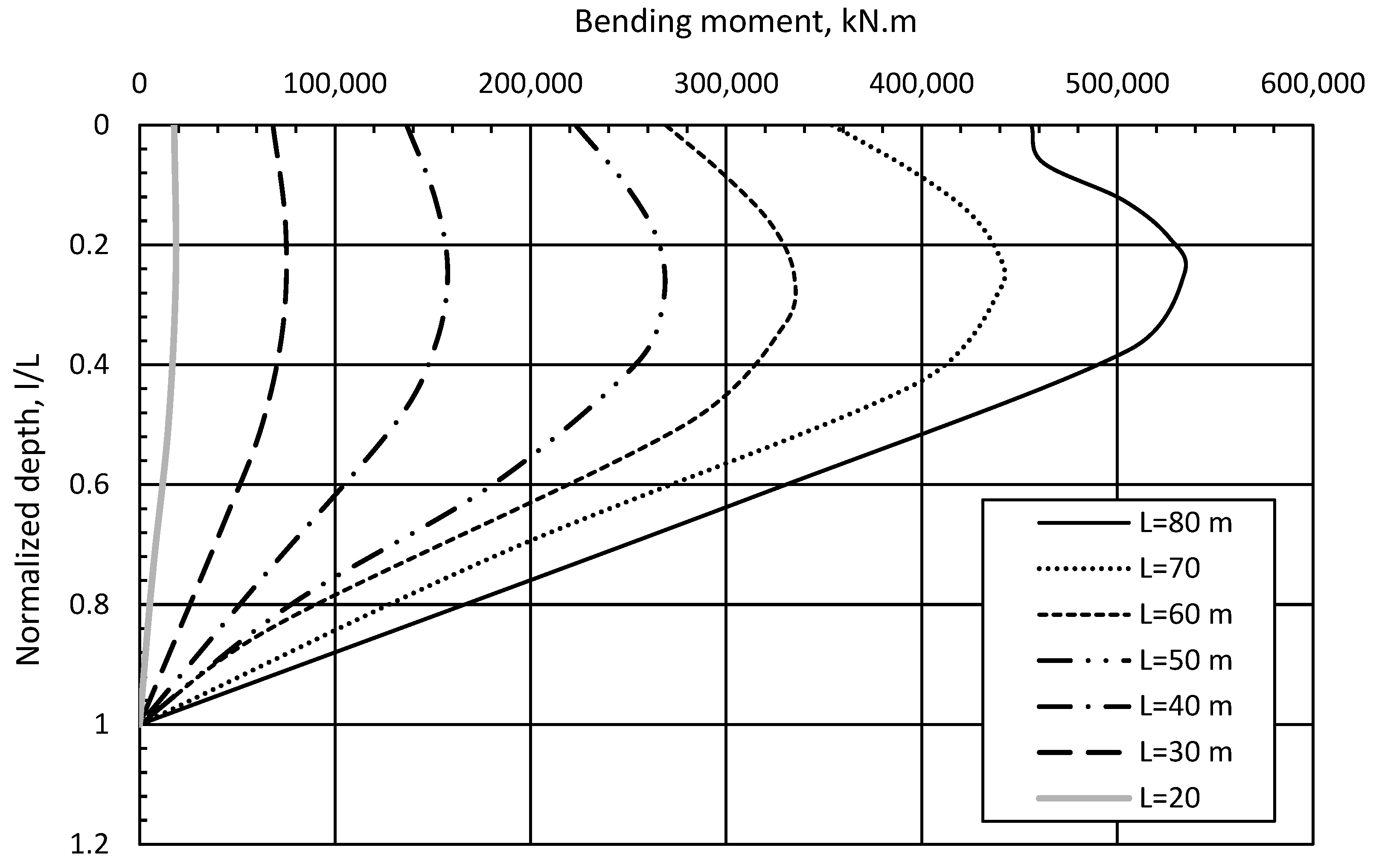
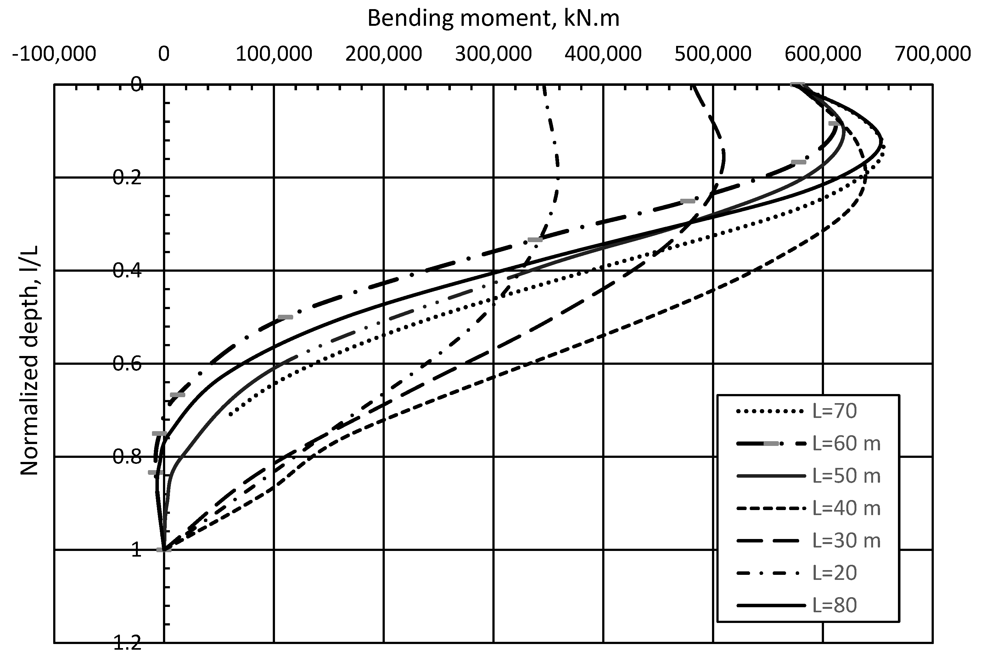
4.3.2. Bending Moment Trends

The maximum bending moments recorded at the pile head varied with both soil strength and L/D ratio. For soft clay, the moment capacity increased significantly with depth, reflecting deeper load transfer. In contrast, stiff soils reached critical bending moments sooner—particularly for short piles—due to limited plastic deformation in the surrounding soil.
The difference in moment magnitudes between pile lengths was modest (around 3–6%) but informative. For example, reducing penetration from 40 to 30 m in soft clay reduced the bending moment due to shallower pivot depths. Figure 17 illustrates these variations across different soil profiles.

5. Conclusions

Monopile foundations remain a practical solution for supporting offshore wind turbines (OWTs), especially as turbine capacities and hub heights continue to increase. This study investigated the lateral performance of monopiles in cohesive soils using 3D finite element analysis, focusing on how variations in soil strength and pile geometry affect load resistance and deformation behavior. It is very important to note that, while this study focuses on monotonic analyses serving as a critical first step in understanding fundamental soil–pile interaction mechanisms, long-term cyclic loading can cause stiffness degradation, accumulated displacements and rotations, and potential pore pressure buildup in cohesive soils—phenomena that may significantly alter pile behavior. As such, it is recommended to extend this work using advanced cyclic constitutive models (e.g., Hss or advanced plasticity model) to evaluate performance under realistic offshore load spectra).
Key conclusions drawn from the numerical analysis are as follows:
  • Effect of Pile Length in Soft Clay (Su1): Increasing the pile length from 20 to 80 m significantly deepened the pivot point and expanded the volume of soil contributing to lateral resistance. The failure mechanism in these cases remained rigid, with clear wedge and rotational soil flow patterns.
  • Failure Pattern in Hard Clay (Su6): For stiff soils, increasing pile length had a limited effect on expanding the resistance zone. A critical depth was observed beyond which additional length did not improve capacity, and local failures occurred near the pile tip. The response was more flexible for higher L/D ratios, concentrating deformation near the pile head.
  • Differences in Failure Zones: In soft clay, failure typically involved two zones—a shallow wedge and deep rotation—whereas hard clay exhibited up to three zones, including lateral confinement effects. These differences emphasize the need to consider soil-specific failure mechanisms during design.
  • Influence on Bending Moments and Shear Forces: Adjusting the pile length relative to a 30 m reference pile resulted in minor variations in maximum bending moment (approximately ±3%) but more noticeable changes in shear force, ranging from 20% to 30%. These shifts correspond to changes in the location of the pile’s rotation axis and soil mobilization depth.
These insights demonstrate the critical influences of soil type and pile geometry on monopile performance. The results contribute to better-informed design practices for OWT foundations; particularly in clay-dominated offshore environments, where balancing rigidity and embedment depth can lead to cost-effective yet structurally robust solutions.

Funding

This research received no external funding.

Data Availability Statement

Data can be shared at a reasonable request.

Acknowledgments

The Researcher would like to thank the Deanship of Graduate Studies and Scientific Research at Qassim University for financial support (QU-APC-2025).

Conflicts of Interest

The author declares no conflicts of interest.

Glossary

SuUndrained shear strength of the soil
DPile diameter
EsYoung’s modulus of the soil
E50refYoung’s modulus of soil at 50% of ultimate reference pressure
EoedrefOedmeter stiffness of the soil at the reference pressure
p p o p , Mean preconsolidation pressure
EpYoung’s modulus of the pile material
RfExponent
FLateral load applied on the foundation
B.MBending moment applied to the foundation
HuMaximum horizontal load capacity
hTower height (m)
koCoefficient of earth pressure at rest
eini.Initial void ratio
PIPlasticity index
LpPile length
M.LMudline
ρ/uDisplacement at M.L
ΘRotation at M.L
MAn exponent describing the variation of soil stiffness with overburden
PrefReference pressure
ULSUltimate limit state
SLSServiceability limit states
c′Soil cohesion
φ′Soil friction angle
ΨDilation angle
ɣsSoil unit weight
vurPoisson’s ratio

Appendix A

Table A1. Variation of ground line displacement for the case of (Lx/2 = 15D) when changing local confinement factor around the monopile for the case of zoning of 3D. (Other tables for 5D and 7D around monopile exists but are not included for brevity.).
TrialDisplacement at 2MNcf (Global)# of ElementsLx/2, ly/2% Difference
10.1930.928,50015D0
20.21870.833,50015D13.3
30.21780.735,05615D12.8
40.21640.641,91315D12.1
50.2220.557,69315D15.0
60.23050.479,94015D19.4

References

  1. OffshoreWind.biz. Siemens Gamesa to Soon Install 21 MW Offshore Wind Turbine Prototype at Danish Test Site—Reports. 10 December 2024. Available online: https://www.offshorewind.biz/2024/12/10/siemens-gamesa-to-soon-install-21-mw-offshore-wind-turbine-prototype-at-danish-test-site-reports/ (accessed on 30 May 2025).
  2. Jeanjean, P.; Zakeri, A.; Zhang, Y.; Andersen, K.H. The new ISO/API P–Y curves in clays and their reconciliation with the PISA framework. In Proceedings of the Offshore Technology Conference, Houston, TX, USA, 2–5 May 2022. OTC-31860-MS. [Google Scholar]
  3. Prendergast, L.J.; Igoe, D. Examination of the reduction in natural frequency of laterally loaded piles due to strain-dependence of soil shear modulus. Ocean Eng. 2022, 258, 111614. [Google Scholar] [CrossRef]
  4. European Wind Energy Association. The European Offshore Wind Industry–Key Trends and Statistics. January 2024. Available online: https://windeuropeb2c.b2clogin.com/windeuropeb2c.onmicrosoft.com/oauth2/v2.0/authorize?client_id=eaec5e8b-1a23-4a93-ab75-ef3d94f47828&response_type=code+id_token&redirect_uri=https%3A%2F%2Fwindeurope.org%2Fsignin&response_mode=form_post&scope=openid&state=https%3A%2F%2Fwindeurope.org%2Fintelligence-platform%2Fproduct%2Foffshore-wind-in-europe-key-trends-and-statistics-2024%2F&nonce=12345&p=b2c_1a_signup_signin (accessed on 29 May 2025).
  5. Broms, B.B. Lateral resistance of piles in cohesive soils. J. Soil Mech. Found. 1964, 90, 27–64. [Google Scholar] [CrossRef]
  6. McClelland, B.; Focht, J.A., Jr. Soil modulus for laterally loaded piles. Trans. Am. Soc. Civ. Eng. 1958, 123, 1049–1063. [Google Scholar] [CrossRef]
  7. Matlock, H. Correlations for design of laterally loaded piles in soft clay. In Proceedings of the 2nd Offshore Technology Conference, Houston, TX, USA, 22–24 April 1970; Volume 1, pp. 577–594. [Google Scholar]
  8. Reese, L.C.; Cox, W.R.; Koop, F.D. Field testing and analysis of laterally loaded piles in stiff clay. In Proceedings of the 7th Offshore Technology Conference, Houston, TX, USA, 5–8 May 1975; Volume 2, pp. 671–690. [Google Scholar]
  9. Berry, H.; Reese, L.C. Analysis of Single Piles Under Lateral Loading; FHWA/TX-79/38+244-l; Center for Highway Research, University of Texas at Austin: Austin, TX, USA, 1979. [Google Scholar]
  10. American Petroleum Institute. Recommended Practice for Planning, Designing, and Constructing Fixed Offshore Platforms; API RP 2A-WSD; API: Washington, DC, USA, 1993. [Google Scholar]
  11. Gerolymos, N.; Giannakos, S.; Drosos, V. Generalized failure envelope for laterally loaded piles: Analytical formulation, numerical verification and experimental validation. Géotechnique 2020, 70, 248–267. [Google Scholar] [CrossRef]
  12. Wang, Z.; Hong, Y.; Ng, C.W.W.; Wang, L.Z.; Mašín, D.; He, B. Cyclic lateral response and failure mechanisms of semi-rigid pile in soft clay: Centrifuge tests and numerical modelling. Can. Geotech. J. 2017, 54, 806–824. [Google Scholar] [CrossRef]
  13. Byrne, B.W.; McAdam, R.; Burd, H.J.; Houlsby, G.T.; Martin, C.M.; Zdravković, L.; Taborda, D.M.G.; Potts, D.M.; Jardine, R.J.; Sideri, M. New design methods for large diameter piles under lateral loading for offshore wind applications. In Proceedings of the Third International Symposium on Frontiers in Offshore Geotechnics, Oslo, Norway, 10–12 June 2015; pp. 705–710. [Google Scholar]
  14. Abdelkader, A.M.R. Investigation of Hybrid Foundation System for Offshore Wind Turbine. Ph.D. Thesis, The University of Western Ontario, London, ON, Canada, 2016. [Google Scholar]
  15. El-Marassi, M. Investigation of Hybrid Monopile-Footing Foundation Systems Subjected to Combined Loading. Ph.D. Thesis, The University of Western Ontario, London, ON, Canada, 2011. [Google Scholar]
  16. Alsharedah, Y.A.; Newson, T.; El Naggar, M.H.; Black, J.A. Lateral ultimate capacity of monopile foundations for offshore wind turbines: Effects of monopile geometry and soil stiffness properties. Appl. Sci. 2023, 13, 12269. [Google Scholar] [CrossRef]
  17. Alsharedah, Y.A.; Black, J.A.; Newson, T.N.; El Naggar, M.H. Centrifuge testing of improved monopile foundation for offshore wind turbines. Ocean Eng. 2023, 285, 115421. [Google Scholar] [CrossRef]
  18. Alsharedah, Y.A.; Black, J.A.; Newson, T.N.; El Naggar, M.H. Monopile and Hybrid Foundation Comparisons Under Lateral Loading. In Proceedings of the 10th International Conference on Physical Modelling in Geotechnics (ICPMG2022), Daejeon, Republic of Korea, 19–23 September 2022; Available online: https://www.issmge.org/publications/publication/monopile-and-hybrid-foundation-system-comparisons-under-monotonic-lateral-loading (accessed on 10 May 2025).
  19. Alsharedah, Y.A. Behavior of Hybrid and Monopile Foundation Systems for Offshore Wind Turbines: Centrifuge Testing and Numerical Modelling. Ph.D. Thesis, The University of Western Ontario, London, ON, Canada, 2022. Available online: https://ir.lib.uwo.ca/etd/8580 (accessed on 10 May 2025).
  20. Byrne, B.W.; McAdam, R.; Burd, H.J.; Houlsby, G.T.; Martin, C.M.; Gavin, K.; Doherty, P.; Igoe, D.; Zdravković, L.; Taborda, D.M.G. Field testing of large diameter piles under lateral loading for offshore wind applications. In Proceedings of the XVI European Conference on Soil Mechanics and Geotechnical Engineering, Edinburgh, UK, 13–17 September 2015; pp. 1255–1260. [Google Scholar]
  21. Zhu, B.; Zhu, Z.; Li, T.; Liu, J.; Liu, Y. Field tests of offshore driven piles subjected to lateral monotonic and cyclic loads in soft clay. J. Waterw. Port Coast. Ocean Eng. 2017, 143, 5017003. [Google Scholar] [CrossRef]
  22. Jeanjean, P. Re-assessment of P–Y curves for soft clays from centrifuge testing and finite element modeling. In Proceedings of the Offshore Technology Conference, Houston, TX, USA, 4–7 May 2009. [Google Scholar] [CrossRef]
  23. Lai, Y.; Wang, L.; Hong, Y.; He, B. Centrifuge modeling of the cyclic lateral behavior of large-diameter monopiles in soft clay: Effects of episodic cycling and reconsolidation. Ocean Eng. 2020, 200, 107048. [Google Scholar] [CrossRef]
  24. Terceros, M.; Achmus, M. An alternative p–y method for piles in cohesive soils under monotonic lateral loading. Geotechnik 2023, 46, 254–270. [Google Scholar] [CrossRef]
  25. Bayton, S.M.; Black, J.A.; Klinkvort, R.T. Centrifuge modelling of long-term cyclic lateral loading on monopiles. In Physical Modelling in Geotechnics, 1st ed.; Routledge: London, UK, 2018; pp. 689–694. [Google Scholar] [CrossRef]
  26. Bisoi, S.; Haldar, S. Dynamic analysis of offshore wind turbine in clay considering soil-monopile-tower interaction. Soil Dyn. Earthq. Eng. 2014, 63, 19–35. [Google Scholar] [CrossRef]
  27. Cherchia, M. Centrifuge Modeling of Hybrid Foundations for Offshore Wind Turbines. Ph.D. Dissertation, Rensselaer Polytechnic Institute, Troy, NY, USA, 2016. [Google Scholar]
  28. Haigh, S. Foundations for offshore wind turbines. In Proceedings of the 8th International Conference on Physical Modelling in Geotechnics, Perth, Australia, 14–17 January 2014; PY-/01/14SP—SN—978-1-138-00152-7T1. [Google Scholar] [CrossRef]
  29. Lehane, B.; Powrie, W.; Doherty, J. Centrifuge model tests on piled footings in clay for offshore wind turbines. In Proceedings of the International Conference in Physical Modelling in Geotechnics, Zurich, Switzerland, 28 June–1 July 2010. [Google Scholar]
  30. Lau, B. Cyclic Behaviour of Monopile Foundations for Offshore Wind Turbines. Ph.D. Dissertation, ProQuest Publishing, University of Cambridge, Ann Arbor, MI, USA, 2015. [Google Scholar]
  31. Wang, X.; Zeng, X.; Yang, X.; Li, J. Feasibility study of offshore wind turbines with hybrid monopile foundation based on centrifuge modeling. Appl. Energy 2018, 209, 127–139. [Google Scholar] [CrossRef]
  32. Zhang, G. A centrifuge study of the seismic response of pile–raft systems embedded in soft clay. Géotechnique 2017, 67, 479–490. [Google Scholar] [CrossRef]
  33. Heidari, M.; Jahanandish, M.; El Naggar, M.H.; Ghahramani, A. Nonlinear cyclic behavior of laterally loaded pile in cohesive soil. Can. Geotech. J. 2014, 51, 129–143. [Google Scholar] [CrossRef]
  34. Klinkvort, R.T.; Hededal, O. Effect of load eccentricity and stress level on pile support for offshore wind turbines. Can. Geotech. J. 2014, 51, 966–974. [Google Scholar] [CrossRef]
  35. Dao, T.P.T. Validation of PLAXIS Embedded Piles for Lateral Loading. Master’s Thesis, Delft University of Technology, Delft, The Netherlands, 2011. [Google Scholar]
  36. Schanz, T.; Vermeer, P.A.; Bonnier, P.G. The hardening soil model: Formulation and verification. In Beyond 2000 in Computational Geotechnics—10 Years of PLAXIS; Balkema: Rotterdam, The Netherlands, 1999; p. 27. [Google Scholar] [CrossRef]
  37. Canadian Geotechnical Society. Canadian Foundation Engineering Manual, 4th ed.; BiTech Publishers: Richmond, BC, USA, 2006; ISBN 0-920505-28-7. [Google Scholar]
Figure 1. Cumulative installed OWT output in various European countries in 2024 [4].
Jmse 13 01222 g001
Figure 2. Geometric notations of the MP (not to scale).
Jmse 13 01222 g002
Figure 3. (a) Shear strength profiles; (b) OCR profiles; (c) ko profiles; (d) E50 profiles.
Jmse 13 01222 g003aJmse 13 01222 g003b
Figure 4. Su/OCR profiles versus depth [21].
Jmse 13 01222 g004
Figure 5. Profiles of the Go field, calibrated versus depth [21].
Jmse 13 01222 g005
Figure 6. Boundary condition notations.
Jmse 13 01222 g006
Figure 7. Isometric snapshot of the FE model.
Jmse 13 01222 g007
Figure 8. Results from the sensitivity analysis.
Jmse 13 01222 g008
Figure 9. Mesh elevation perspective.
Jmse 13 01222 g009
Figure 10. Field versus FE load–displacement curves [21].
Jmse 13 01222 g010
Figure 11. Inclinometer flexural moment data (dots) versus FE results (solid line) [21].
Jmse 13 01222 g011
Figure 12. Monopile load–displacement curves in (a) Su1 and (b) Su6.
Jmse 13 01222 g012
Figure 13. (ad) Monopiles in soft clay; (eh) monopiles in hard clay.
Jmse 13 01222 g013aJmse 13 01222 g013bJmse 13 01222 g013c
Figure 14. Bending moment versus normalized depth for MP in soft soil (CL1).
Jmse 13 01222 g014
Figure 15. Bending moment versus normalized depth for the stiff soil (CL6) profile.
Jmse 13 01222 g015
Figure 16. Effects of soil profiles on normalized pivot location.
Jmse 13 01222 g016
Figure 17. Effects of soil shear strength on the maximum bending moment.
Jmse 13 01222 g017
Table 1. Geometries of the FE models.
L, mL/DFoundation Systeme/DtV, kN
203.33Monopile6.83Own weight 1
3056.83
406.676.83
508.336.83
60106.83
7011.676.83
8013.336.83
D: pile’s diameter; L: depth of embedment; e: eccentricity of applied loads (m); Dt: tower’s diameter; 1: uniformly distributed.
Table 2. Calibrated model soil properties of the case study of [8].
ParameterClay1Clay2Clay3
c′, kPa4.23613
Ψ, degrees000
ϕ, degrees10100
p p o p , k P a 151515
p r e f , k P a 4171100
eini.4.233.2853.285
ɣ, kN/m317.91515
E o e d r e f , k P a 140620002000
E 50 r e f , k P a 175825002500
E u r r e f , k P a 500075007500
vur0.20.20.2
m0.60.81
PI, %808080
ko, NC0.540.540.54
Rf0.90.90.9
Depth, m0–55–1010–24.5
Type of analysisUndrained AUndrained AUndrained B
Disclaimer/Publisher’s Note: The statements, opinions and data contained in all publications are solely those of the individual author(s) and contributor(s) and not of MDPI and/or the editor(s). MDPI and/or the editor(s) disclaim responsibility for any injury to people or property resulting from any ideas, methods, instructions or products referred to in the content.

