

Optimizing Catamaran Hull Form for Resistance Reduction: Methodology and Case Study

 ,
, 
 ,
,
Abstract
1. Introduction
- (1)
- A structured methodology is proposed to assist engineers in identifying optimal catamaran geometric parameters—specifically, vessel length, demihull separation, and hull symmetry—during the design stage. This approach supports the parameter selection, definition of variation limits, and selection of appropriate resistance evaluation techniques tailored to the design task;
- (2)
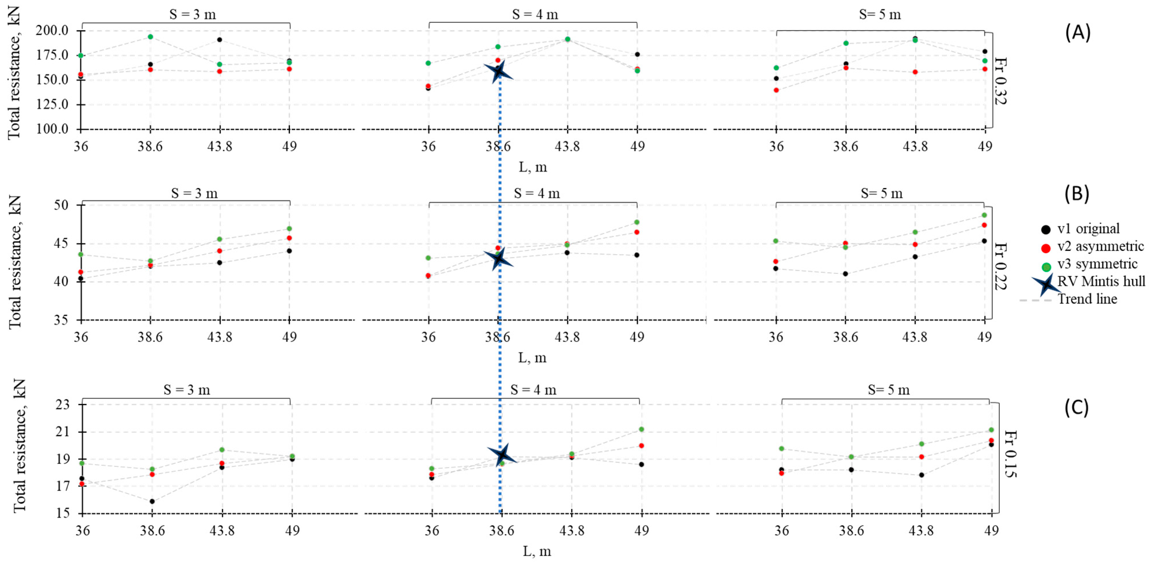
- A graphical system for presenting simulation results is introduced, allowing an intuitive interpretation of total resistance trends across various geometric configurations and operational speeds. This method, illustrated in paragraph of results, enables a comprehensive comparison of multiple design variants within a clear visual framework;
- (3)
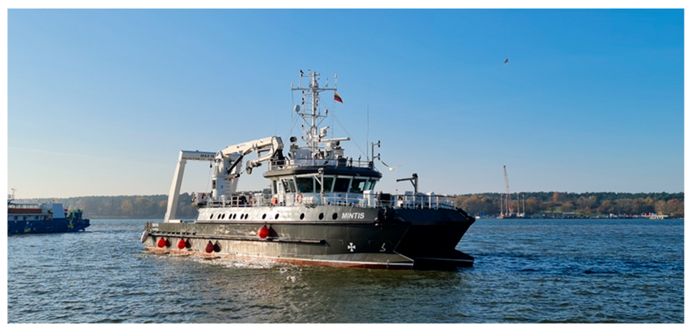
- The methodology is applied and validated through a case study of the research vessel Mintis, using CFD simulations verified by experimental data. This demonstrates the practical value of the approach in supporting resistance-based optimization during vessel design stage.
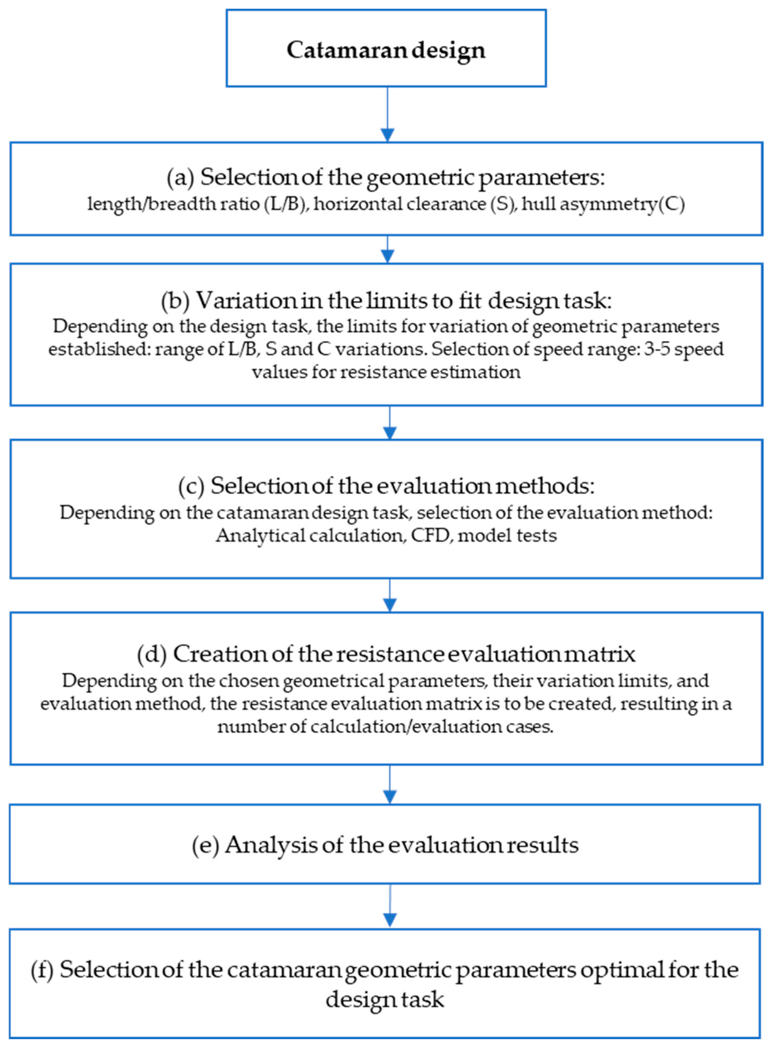
2. Methodology
- -
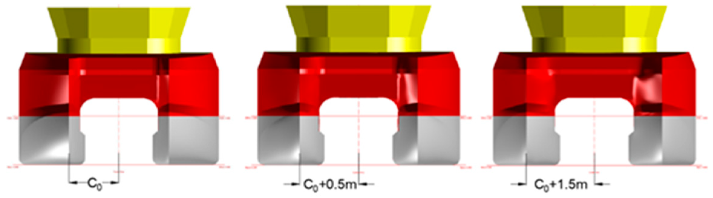
- Selection of geometric parameters based on design task limitations (length, demihull separation, hull asymmetry, etc.);
- -
- Guidelines for setting the variation limits of the vessel’s geometric parameters, including advice on establishing limits and variation steps;
- -
- Selection of evaluation method, depending on design task parameters (hull form, vessel speed);
- -
- Creation of an evaluation matrix and calculation of vessel total resistance;
- -
- Analysis of the evaluation results and selection of optimal geometric parameters for the design task.
- (1)
- The proposed methodology enables a more in-depth analysis of geometric parameters that can be varied during the design process within the framework of the design task. This allows the introduction of key design modifications that positively impact the vessel’s operational performance;
- (2)
- The proposed methodology streamlines the selection process of optimal catamaran geometric characteristics by supporting the definition of their variation limits, selection of total resistance evaluation methods, and, most importantly, the application of effective received data analysis principles to determine the optimal catamaran configuration;
- (3)
- The proposed representation methods of the total resistance evaluation results supports engineers in determining appropriate design geometric parameters, thereby minimizing potential negative impacts during the vessel exploitation phase.
3. Case Study Conditions
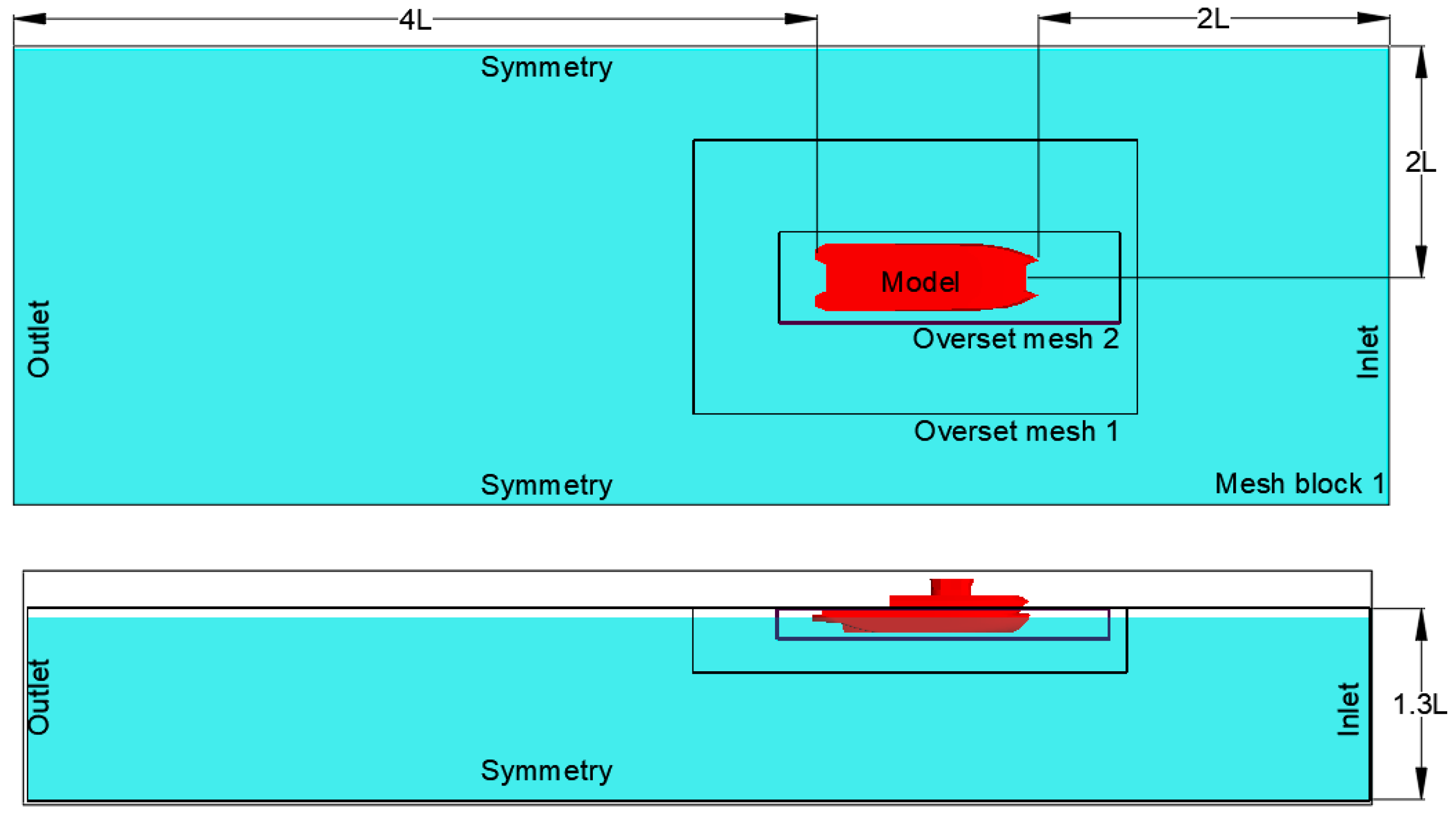
4. Computational Method
Verification of the CFD Code
5. Validation of CFD Code
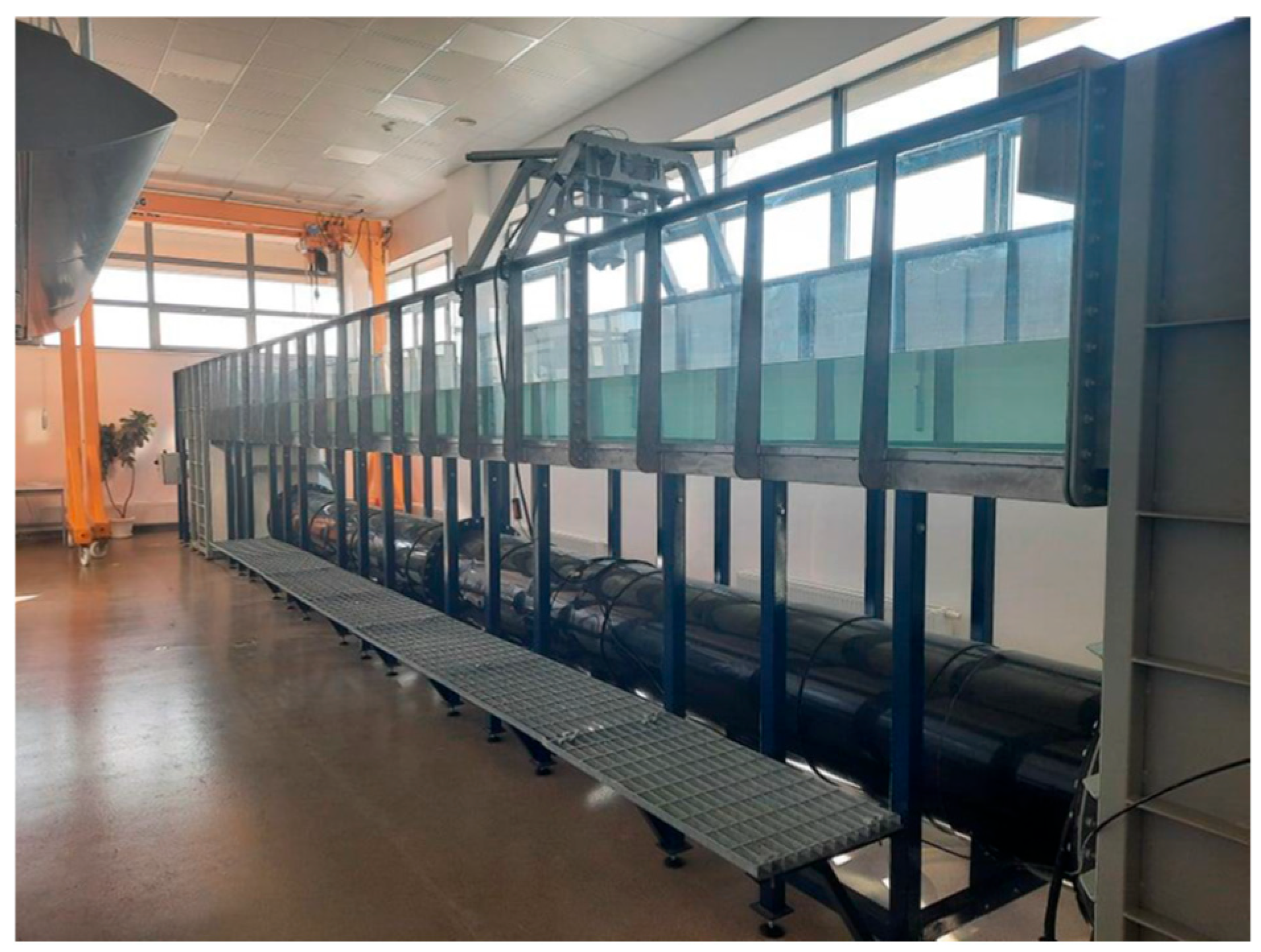
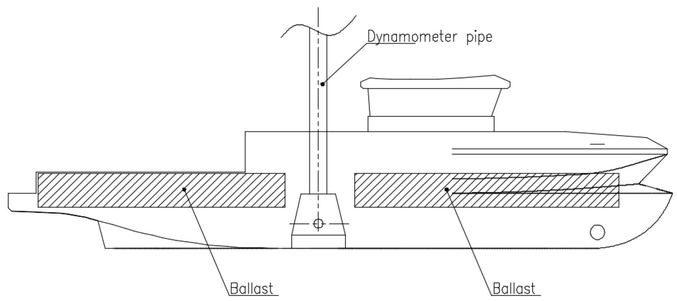
Experimental Conditions
6. Results and Discussion
7. Conclusions
Author Contributions
Funding
Data Availability Statement
Conflicts of Interest
Abbreviations
| CFD | Computational fluid dynamics |
| RANS | Reynolds-Averaged Navier–Stokes |
| RV | Research vessel |
| ITTC | International Towing Tank Conference |
| SEEMP | Ship Energy Efficiency Management Plan |
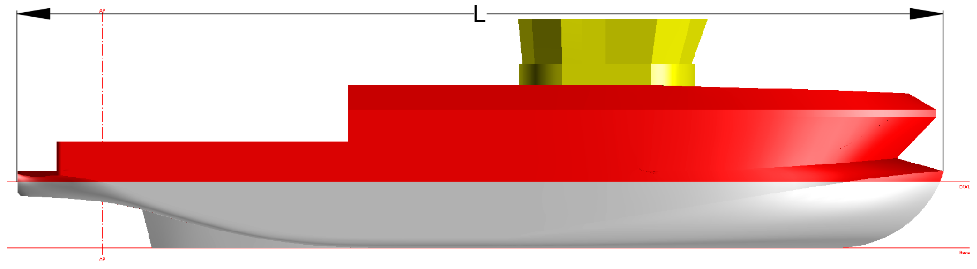
| L | Ship length |
| B | Ship breadth |
| D | Ship draught |
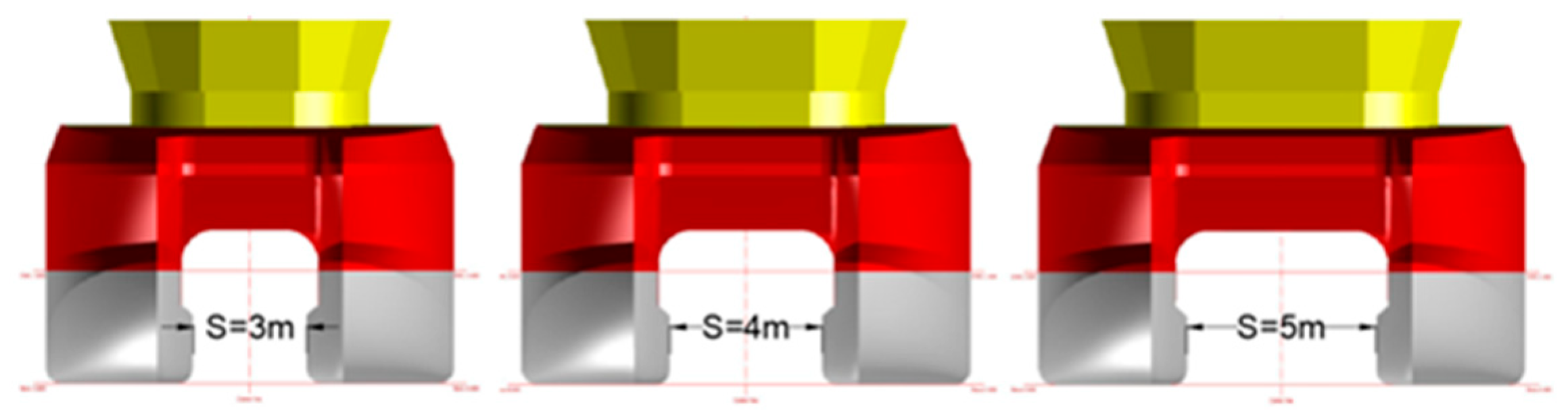
| S | Catamaran demihull separation |
| C0 | Original RV “Mintis” symmetry value |
| Fr | Froude number |
| VOF | Volume of fluid method |
| GHG | Greenhouse gas |
| EEDI | Energy Efficiency Design Index |
| IMO | International Maritime Organization |
| V | Velocity vector field |
| t | Time |
| Kinematic viscosity factor | |
| Vector Laplace operator | |
| Nabla operator | |
| Density | |
| Pressure | |
| F | Field of mass forces |
Appendix A
Appendix A.1

| Hull Version 1 (S/L Ratio) | Hull Length L, m | Demihull Spacing S, m | Resistance, kN (Fr 0.15/Fr 0.22/Fr 0.32) |
|---|---|---|---|
| v 1-1 (0.071) | 49.0 | 5 | 20.08/45.32/179.00 |
| v 1-2 (0.079) | 43.8 | 5 | 17.80/43.26/192.09 |
| v 1-3 (0.081) | 49.0 | 3 | 19.00/44.00/169.03 |
| v 1-4 (0.090) | 38.6 | 5 | 15.86/42.00/165.89 |
| v 1-5 (0.091) | 43.8 | 3 | 18.36/42.50/190.48 |
| v 1-6 (0.091) | 49.0 | 4 | 18.58/43.48/175.53 |
| v 1-7 (0.097) | 36.0 | 5 | 18.20/41.70/151.54 |
| v 1-8 (0.100) | 43.8 | 4 | 19.10/43.80/191.29 |
| v 1-9 (0.103) | 38.6 | 3 | 19.20/43.00/161.88 |
| v 1-10 (0.110) | 36.0 | 3 | 17.54/40.44/153.41 |
| v 1-11 (0.110) | 38.6 | 4 | 18.20/41.00/166.57 |
| v 1-12 (0.125) | 36.0 | 4 | 17.62/40.72/141.52 |
| Hull Version 2 (S/L Ratio) | Hull Length L, m | Demihull Spacing S, m | Resistance, kN (Fr 0.15/Fr 0.22/Fr 0.32) |
|---|---|---|---|
| v 2-1 (0.071) | 49.0 | 5 | 20.36/47.38/161.22 |
| v 2-2 (0.079) | 43.8 | 5 | 19.16/44.86/157.86 |
| v 2-3 (0.081) | 49.0 | 3 | 19.22/45.70/161.22 |
| v 2-4 (0.090) | 38.6 | 5 | 19.14/45.02/162.13 |
| v 2-5 (0.091) | 43.8 | 3 | 18.68/44.00/158.42 |
| v 2-6 (0.091) | 49.0 | 4 | 19.96/46.44/161.22 |
| v 2-7 (0.097) | 36.0 | 5 | 17.96/42.62/139.37 |
| v 2-8 (0.100) | 43.8 | 4 | 19.26/44.96/190.95 |
| v 2-9 (0.103) | 38.6 | 3 | 17.88/42.14/160.42 |
| v 2-10 (0.110) | 36.0 | 3 | 17.16/41.24/155.51 |
| v 2-11 (0.110) | 38.6 | 4 | 18.62/44.36/169.71 |
| v 2-12 (0.125) | 36.0 | 4 | 17.86/40.80/143.71 |
| Hull Version 3 (S/L Ratio) | Hull Length L, m | Demihull Spacing S, m | Resistance, kN (Fr 0.15/Fr 0.22/Fr 0.32) |
|---|---|---|---|
| v 3-1 (0.071) | 49.0 | 5 | 21.16/48.68/169.32 |
| v 3-2 (0.079) | 43.8 | 5 | 20.10/46.48/189.95 |
| v 3-3 (0.081) | 49.0 | 3 | 19.20/46.90/167.38 |
| v 3-4 (0.090) | 38.6 | 5 | 19.16/44.50/186.84 |
| v 3-5 (0.091) | 43.8 | 3 | 19.66/45.54/165.64 |
| v 3-6 (0.091) | 49.0 | 4 | 21.20/47.72/159.06 |
| v 3-7 (0.097) | 36.0 | 5 | 19.76/45.30/161.84 |
| v 3-8 (0.100) | 43.8 | 4 | 19.36/44.74/191.48 |
| v 3-9 (0.103) | 38.6 | 3 | 18.24/42.72/193.36 |
| v 3-10 (0.110) | 36.0 | 3 | 18.68/43.56/174.67 |
| v 3-11 (0.110) | 38.6 | 4 | 18.66/43.64/183.46 |
| v 3-12 (0.125) | 36.0 | 4 | 18.30/43.08/166.64 |
References
- International Maritime Organization (IMO). Energy Efficiency Design Index (EEDI) and Ship Energy Efficiency Management Plan (SEEMP); MARPOL Annex VI, Resolution MEPC.203(62); International Maritime Organization (IMO): London, UK, 2011. [Google Scholar]
- Dubrovskiy, V.A. Attractive potential of multi-hulls. Naval Architect; The Royal Institution of Naval Architects: London, UK, 1997; pp. 18–19. [Google Scholar]
- Miao, A.; Zhao, M.; Wan, D. CFD based multi-objective optimization of S60 Catamaran considering demi hull shape and searation. Appl. Ocean Res. 2020, 97, 102071. [Google Scholar] [CrossRef]
- Campana, E.F.; Peri, D.; Tahara, Y.; Stern, F. Shape optimization in ship hydrodynamics using computational fluid dynamics. Comput. Methods Appl. Mech. Eng. 2006, 196, 634–651. [Google Scholar] [CrossRef]
- Stern, F.; Wilson, R.; Longo, J.; Carrica, P.; Xing, T.; Tahara, Y.; Simonsen, C.; Kim, J.; Shao, J.; Irvine, M.; et al. Paradigm for development of simulation based design for ship hydrodynamics. In Proceedings of the 8 th International Conference on Numerical Ship Hydrodynamics, Busan, Republic of Korea, 22–25 September 2003. [Google Scholar]
- Papanikolaou, A. A Holistic Approach to Ship Design; Springer Internation Publishing: Berlin/Heidelberg, Germany, 2019; ISBN 978-3-030-02809-1. [Google Scholar]
- Dogrul, A.; Kahramanoglu, E.; Cakici, F. Numerical prediction of interference factor in motions and added resistance for Delft catamaran 372. Ocean Eng. 2021, 223, 108687. [Google Scholar] [CrossRef]
- Cheng, X.; Huang, X.; Xu, D.; Zhao, Z.; Liu, H.; Kong, M.; Ji, R. Ship optimization based on fully-parametric models for hull, propeller and rudder. J. Mar. Sci. Eng. 2024, 12, 1635. [Google Scholar] [CrossRef]
- ITTC Recommended Procedures and Guidelines. Practical Guideline for Ship Resistance CFD. 2014. Available online: https://www.ittc.info/media/11718/0_0.pdf (accessed on 1 January 2025).
- Haase, M.; Zurcher, K.; Davidson, G.; Binns, J.B.; Thomas, G.; Bose, N. Novel CFD-based full-scale resistance prediction for large medium-speed catamarans. Ocean Eng. 2016, 111, 198–208. [Google Scholar] [CrossRef]
- Kleven Godø, J.M.; Steen, S.; Faltinsen, O.M. An Efficient Method for Design and Powering Prediction of Fast Slender Catamarans. Ocean Eng. 2023, 286, 115589. [Google Scholar] [CrossRef]
- Djačkov, V.; Žapnickas, T.; Čerka, J.; Mickevičienė, R.; Ašmontas, Ž.; Norkevičius, L.; Ronkaitytė, I.; Zhou, P.; Blanco-Davis, E. Numerical simulation of a research vessel’s aftpart hull form. Ocean Eng. 2018, 169, 418–427. [Google Scholar] [CrossRef]
- Zaraphonitis, G.; Spanos, D.; Papanikolaou, A. Numerical and Experimental Study on the Wave Resistance of Fast Displacement Asymmetric Catamarans. In Proceedings of the International Euro Conference on High Performance Marine Vehicles, HIPER’01, Hamburg, Germany, 2–5 May 2001. [Google Scholar]
- Farkas, A.; Degiuli, N.; Martić, I. Numerical investigation into the interaction of resistance components for a series 60 catamaran. Ocean Eng. 2017, 146, 151–169. [Google Scholar] [CrossRef]
- Jamaluddin, A.; Utama, I.K.A.P.; Aryawan, B.W.; Widodo, B. Experimental investigations into the resistance components of asymmetrical catamarans with variation of hull spacing and stagger. Trans. RINA Int. J. Small Craft Technol. 2012, 154 Pt B1, B13–B18. [Google Scholar]
- Wang, H.; Zhu, R.; Zha, L.; Gu, M. Experimental and numerical investigation on the resistance characteristics of a high-speed planing catamaran in calm water. Ocean Eng. 2022, 258, 111837. [Google Scholar] [CrossRef]
- Xing-Kaeding, Y.; Papanikolaou, A. Optimization of the Propulsive Efficiency of a Fast Catamaran. J. Mar. Sci. Eng. 2021, 9, 492. [Google Scholar] [CrossRef]
- Aung, M.Z.; Nazemian, A.; Boulougouris, E.; Wang, H.; Duman, S.; Xu, X. Establishment of a design study for comprehensive hydrodynamic optimisation in the preliminary stage of the ship design. Ships Offshore Struct. 2024, 19, 793–806. [Google Scholar] [CrossRef]
- Bari, G.S.; Matveev, K.I. Hydrodynamics of single-deadrise hulls and their catamaran configurations. Int. J. Nav. Archit. Ocean Eng. 2017, 9, 205–314. [Google Scholar] [CrossRef]
- He, J.; Zhang, C.; Zhu, Y.; Zou, L.; Li, W.; Noblesse, F. Interference effects on the Kelvin wake of a catamaran represented via a hull-surface distribution of sources. Eur. J. Mech. B/Fluids 2016, 56, 1–12. [Google Scholar] [CrossRef]
- Shi, G.; Matveev, K.I. Numerical Investigation of the Resistance of a Zero-Emission Full-Scale Fast Catamaran in Shallow Water. J. Mar. Sci. Eng. 2021, 9, 563. [Google Scholar] [CrossRef]
- Broglia, R.; Jacob, B.; Zaghi, S.; Stern, F.; Olivieri, A. Experimental investigation of interference effects for high-speed catamarans. Ocean Eng. 2014, 76, 75–85. [Google Scholar] [CrossRef]
- Zaghi, S.; Broglia, R.; Di Mascio, A. Analysis of the interference effects for high-speed catamarans by model tests and numerical simulations. Ocean Eng. 2011, 38, 2110–2122. [Google Scholar] [CrossRef]
- Yun, L.; Bliault, A.; Rong, H.Z. High Speed Catamarans and Multihulls. Technology, Performance and Applications; Springer: New York, NY, USA, 2019; ISBN 978-1-4939-7889-2. [Google Scholar] [CrossRef]
- Alferjev, M.Y.; Madorsky, G.S. Inland Transport Catamarans; USSR, UDK 629.541.001.2; Transport Press: Moscow, Russia, 1976. (In Russian) [Google Scholar]
- Irkal, M.A.; Nallayarasu, S.; Bhattacharyya, S. CFD approach to roll damping of ship with bilge keel with experimental validation. Appl. Ocean. Res. 2016, 55, 1–17. [Google Scholar] [CrossRef]
- Ghadimi, P.; Dashtimanesh, A.; Faris, M.; Najafi, A. Investigation of free surface flow generated by a planing flat plate using smoothed particle hydrodynamics method and FLOW3D simulations. IMech Part M J. Eng. Marit. Environ. 2013, 227, 125–135. [Google Scholar] [CrossRef]
- Richardson, L.F. The Approximate Arithmetical Solution by Finite Differences of Physical Problems Involving Differential Equations, with an Application to the Stresses in a Masonary Dam. Philos. Trans. R. Soc. London 1910, 210, 307–357. [Google Scholar]
- Roache, P.J. Verification and Validation in Computational Science and Engineering; Hermosa Publishers: Albuquerque, NM, USA, 1998. [Google Scholar]
- Wolfson Unit [Online]. Available online: https://www.wumtia.soton.ac.uk/products/ (accessed on 10 February 2025).
- ITTC Recommended Procedures and Guidelines, 7.5-02-02-01, Resistance Test. Available online: https://ittc.info/media/1217/75-02-02-01.pdf (accessed on 1 April 2025).
- Volker, B. Practical Ship Hydrodynamics; Elsevier Ltd.: Amsterdam, The Netherlands, 2012; Chapter 3; pp. 84–93. [Google Scholar] [CrossRef]
- Dubrovsky, V. Specificity and Designing of Multi- Hull Ships and Boats; Nova Science Publishers Inc.: Hauppauge, NY, USA, 2016; ISBN 978-1-63484-615-8. [Google Scholar]
- Sun, W.; Gong, Y.; Zhang, K. Preliminary Development of a Novel Salvage Catamaran and Evaluation of Hydrodynamic Performance. J. Mar. Sci. Eng. 2025, 13, 680. [Google Scholar] [CrossRef]
- Molland, A.; Turnock, S.; Hudson, D. Ship Resistance and Propulsion: Practical Estimation of Ship Propulsive Power; Cambridge University Press: Cambridge, UK, 2011; 537p. [Google Scholar]
- Voytkunskiy, Y.I. Resistance of Ship, Ship Propulsion; Hydromechanics, Devices; Sudostroyenie: Leningrad, Russia, 1988; Volume I. (In Russian) [Google Scholar]


| Grid | Base Size | Resistance Result, kN | Convergence Index (GCI) |
|---|---|---|---|
| Coarse | 1.125 | 21.58 | - |
| Medium | 0.75 | 21.41 | 1.54% |
| Fine | 0.5 | 20.9 | 0.52% |
| Original Vessel | Unit | Value | Model | Value | Unit |
|---|---|---|---|---|---|
| Length (LN) | m | 38.6 | Length (LM) | 1.49 | m |
| Breadth (BN) | m | 12.0 | Breadth (BM) | 0.46 | m |
| Draft (dN) | m | 3.0 | Draft (dM) | 0.12 | m |
| Speed (vN) | kt | 8.5 | Speed (vM) | 1.66 | kt |
| Speed (vN) | m/s | 4.37 | Speed (vM) | 0.86 | m/s |
| Water depth (HT) | m | 0.5 | Froude number (Fr) | 0.22 | - |
| Vessel Speed, kn | Scale Model Resistance, N (Recalculated at Full Scale, kN) | Full Scale CFD Resistance, kN | Difference, % |
|---|---|---|---|
| 6 (3.1 m/s) | 1.5 (18 kN) | 19.2 kN | −6.5% |
| 8.5 (4.3 m/s) | 3.3 (41.3 kN) | 43 kN | −4.0% |
| 12.5 (6.43 m/s) | 10.7 (158.5 kN) | 161 kN | −1.5% |
Disclaimer/Publisher’s Note: The statements, opinions and data contained in all publications are solely those of the individual author(s) and contributor(s) and not of MDPI and/or the editor(s). MDPI and/or the editor(s) disclaim responsibility for any injury to people or property resulting from any ideas, methods, instructions or products referred to in the content. |
© 2025 by the authors. Licensee MDPI, Basel, Switzerland. This article is an open access article distributed under the terms and conditions of the Creative Commons Attribution (CC BY) license (https://creativecommons.org/licenses/by/4.0/).
Share and Cite
Iamshchikov, E.; Janutenienė, J.; Mažeika, P.; Mickevičienė, R.; Villa, D.; Zapnickas, T.; Djackov, V. Optimizing Catamaran Hull Form for Resistance Reduction: Methodology and Case Study. J. Mar. Sci. Eng. 2025, 13, 1160. https://doi.org/10.3390/jmse13061160
Iamshchikov E, Janutenienė J, Mažeika P, Mickevičienė R, Villa D, Zapnickas T, Djackov V. Optimizing Catamaran Hull Form for Resistance Reduction: Methodology and Case Study. Journal of Marine Science and Engineering. 2025; 13(6):1160. https://doi.org/10.3390/jmse13061160
Chicago/Turabian StyleIamshchikov, Evgenii, Jolanta Janutenienė, Pranas Mažeika, Rima Mickevičienė, Diego Villa, Tomas Zapnickas, and Vasilij Djackov. 2025. "Optimizing Catamaran Hull Form for Resistance Reduction: Methodology and Case Study" Journal of Marine Science and Engineering 13, no. 6: 1160. https://doi.org/10.3390/jmse13061160
APA StyleIamshchikov, E., Janutenienė, J., Mažeika, P., Mickevičienė, R., Villa, D., Zapnickas, T., & Djackov, V. (2025). Optimizing Catamaran Hull Form for Resistance Reduction: Methodology and Case Study. Journal of Marine Science and Engineering, 13(6), 1160. https://doi.org/10.3390/jmse13061160