Article

Stability Analysis of Marine Scaffold Under Coupled Environmental Loads

1
School of Civil Engineering, Chongqing University, Chongqing 400045, China
2
State Key Laboratory of Safety and Resilience of Civil Engineering in Mountain Area, Chongqing 400045, China
3
Key Laboratory of New Technology for Construction of Cities in Mountain Area, School of Civil Engineering, Chongqing University, Chongqing 400045, China
*
Author to whom correspondence should be addressed.
J. Mar. Sci. Eng. 2025, 13(6), 1141; https://doi.org/10.3390/jmse13061141
Submission received: 25 April 2025 / Revised: 21 May 2025 / Accepted: 3 June 2025 / Published: 8 June 2025
(This article belongs to the Section Ocean Engineering)

Abstract

:
Structural instability in marine scaffold systems often causes serious economic losses and casualties. In this study, a multi-parameter coupled model was established based on the MIDAS GEN finite element analysis platform to investigate the influence mechanisms of key parameters on the overall stability of marine scaffold systems. To quantify the impact levels of the key parameters, a sensitivity analysis framework was established using an orthogonal experimental design approach and the corresponding compliance detection index and instability early-warning mechanisms were proposed. The results indicate that the overall stability of the scaffold system initially increases and then decreases with the rise in the adjustable base height. Variations in the cantilever length of the adjustable bracket within the range of 100–650 mm have no significant effect on the system’s overall stability. The absence of diagonal brace at the bottom, top, and facade ends significantly reduces structural stability. Increased vertical offset markedly degrades stability, whereas horizontal offset within ±5 mm has a negligible effect. The key parameters affecting the structural stability, ranked in descending order of significance, are as follows: absence of diagonal braces, verticality offset of the vertical bar, height of the adjustable base, horizontality offset of the horizontal bar, and cantilever length of the adjustable bracket. Finally, an early-warning assessment system for the scaffold structure was established. The research findings provide valuable guidance for optimizing marine scaffold design, enhancing construction safety, and formulating relevant standards and specifications.

1. Introduction

The scaffold system meets the requirements of adaptability, safety, and stability of temporary support structures during the construction process, making it an essential temporary facility in project execution [1,2,3]. With modular assembly characteristics and engineering versatility [4], the marine scaffold has become the core temporary support structure of marine engineering such as ship, cross-sea bridge, and offshore platform engineering, as shown in Figure 1. Safety accidents caused by the instability of scaffold structure will lead to serious economic losses and casualties [5,6,7]. Exploring the causes of accidents that lead to the scaffold structure failure has gradually become a research hotspot [8,9,10]. The structural failure of scaffold systems may be primarily attributed to three key factors: suboptimal design configurations, deviations during the installation process, and unregulated on-site loading conditions [11,12]. Additionally, the initial geometric imperfections of the scaffold system significantly influence its buckling behavior, thereby compromising the overall structural stability [13]. Therefore, systematically analyzing the stability-influencing factors of scaffold systems and establishing a quantitative evaluation model for key parameters hold significant theoretical and practical value.
Eccentric loading substantially diminishes the ultimate bearing capacity of scaffold systems, and the ultimate bearing capacity exhibits a strong inverse relationship with transverse load magnitude [14]. The bending-induced geometric imperfections in structural members reduce the scaffold system’s ultimate bearing capacity by approximately 10% compared to the reference model under ideal conditions [15]. Properly configured diagonal brace members can substantially enhance the scaffold system’s bearing capacity while maintaining axial stresses within a limited elastic range during loading [16,17]. Without the installation of diagonal bracing, the overall stability bearing capacity of scaffold is reduced by nearly 50% [18]. When the cantilever length of the adjustable bracket and the height of the adjustable base are synchronously set to 650 mm, the scaffold system’s bearing capacity decreases to 70% of its reference value [19]. The scaffold system exhibits distinct failure modes depending on the cantilever length of adjustable brackets: overall buckling dominates under short cantilever conditions, while local instability occurs at vertical bar tops under long cantilever conditions [20]. The key factors affecting the overall stability of a scaffold system include load combination mode, initial geometric imperfections of members, arrangement of diagonal braces, cantilever length of adjustable braces, and height of adjustable base [21,22,23].
Current research on scaffold system stability predominantly adopts the single-variable control method to investigate the influence of individual parameters on structural bearing capacity and stability performance [24,25,26]. Ewa Błazik-Borowa’s research elucidates the stiffness evolution and load-bearing characteristics of joint connections under varying loading conditions [27]. Decreasing the step distance and transverse spacing of the vertical bar and arranging the diagonal braces reasonably can significantly enhance the bearing performance of scaffold system [28]. The structural form of the upper joint and its anti-slip characteristics have a significant regulatory effect on the stability and strength of the scaffold system [29]. Some scholars have carried out an overall stability analysis of scaffold systems using finite element numerical simulations, but existing models exhibit notable limitations in fully accounting for the coupled effects of member geometric imperfections, arrangement of diagonal braces, and adjustable component properties on structural stability [30,31]. Single-factor analysis may lead to unstable results and deviate from the multifactor influences present in actual working environments [32]. Furthermore, research concerning instability warning mechanisms for scaffold systems remains nascent, with no established early warning system for the key parameters currently available [33,34]. Consequently, developing a multi-parameter coupling model to investigate parameter interaction mechanisms and establish quantitative detection and grading early warning index holds substantial theoretical significance and practical engineering value.
To address the limitations in current stability assessments of marine scaffold systems, particularly the insufficient consideration of parameter interactions and unclear coupling mechanisms, this study develops a multi-parameter coupled model based on a finite element platform. The model’s accuracy is validated through comparison with field-measured modal data. Based on this validated model, a comprehensive analysis is conducted to investigate the combined effects of adjustable base height, cantilever length of the adjustable bracket, the arrangement of the diagonal braces, and bar offset on structural stability. The analysis results reveal a nonlinear “increase–then–decrease” relationship between base height and overall stability. By integrating orthogonal experimental design and sensitivity analyses, the influence weights of key parameters are quantitatively determined. Furthermore, a multi-parameter stability grading and early-warning mechanism is established, enabling timely identification of potential instability risks. The outcomes of this research provide theoretical foundations and technical support for the optimization of scaffolding design, risk control, and the development of relevant engineering standards in marine construction.

2. Methodology

2.1. Fundamental Assumption

The finite element software used in this study is MIDAS GEN 2021 (Version 3.1), which is a general-purpose structural analysis and design software developed by MIDAS Information Technology Co., Ltd. (Beijing, China). In this study, MIDAS GEN 2021 was employed to develop a finite element model of the modular scaffolding system. The platform facilitated both static and nonlinear buckling analyses to evaluate the influence of key structural parameters on global stability.
The finite element model in this study is established under the following fundamental assumptions: (1) Scaffold members are assumed to follow an ideal elastic–plastic constitutive relationship and are free from initial geometric imperfections. (2) The joint connection between the vertical bars is simulated by a rigid connection, and the joint connection between the remaining bars and the vertical bar is simulated by semi-rigid connection, as shown in Figure 2. (3) At the intersection point of the upright bar, horizontal bar, and diagonal braces within the scaffold system, the connections are assumed to exhibit no eccentric force transmission. (4) The bottom adjustable base is assumed to be hinged to the foundation with no consideration of foundation deformation.
The model adopts material parameters in accordance with the standard mechanical properties of Q235 structural steel. Detailed statistical data are shown in Table 1. The Q235 steel specimens were sourced from Chongqing Iron and Steel Group Co., Ltd. (Chongqing, China), a leading steel manufacturer in China. The composition and content of the main alloying elements in the selected steel are shown in Table 2.
The components of scaffold system include vertical bar, horizontal bar, diagonal brace, adjustable base, adjustable bracket, connectors, and other auxiliary components. Based on the actual dimensions of the scaffold system used on-site, the geometric parameters of the model are standardized: the vertical and horizontal bars have a cross-sectional diameter of 48.3 mm and a wall thickness of 2.5 mm, while the diagonal brace members have a diameter of 38 mm with the same wall thickness. The model specifications of the adjustable base and the adjustable bracket are determined according to the size of the vertical rod, including the screw bolt, nut, support, and bottom plate. Connectors and other auxiliary components are determined according to the actual needs of the project.

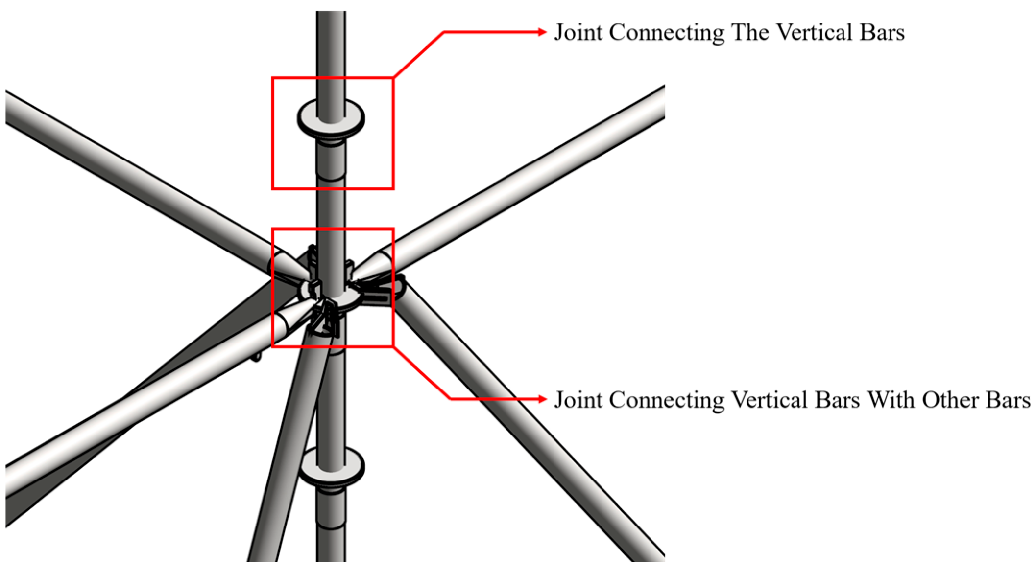
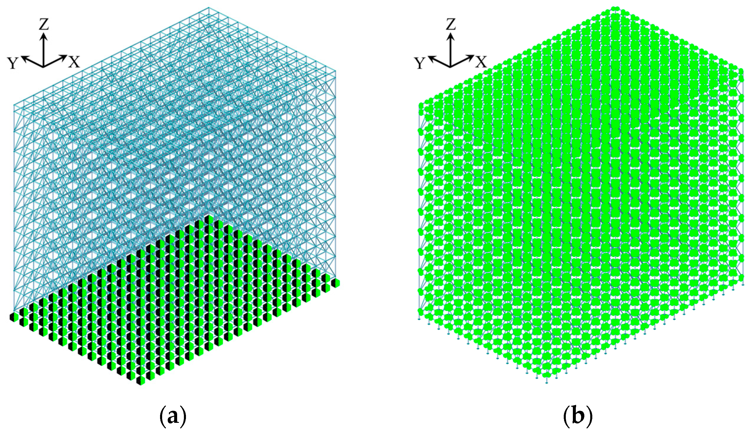
2.2. Model Construction

The width and length of the frame body are designed in unequal sizes and the differential spacing is maintained. The spacing between the vertical bars and the step distance of the horizontal bars are 0.9 m and 1.5 m, respectively, which are the conventional parameters of the project. To ensure the meaningful influence of verticality and horizontality on frame stability, the structural height is set to avoid excessively low value. To investigate the influence of the absence of whole layer of diagonal braces on the overall stability of the scaffold system, the number of layers of the scaffold structure model is designed to be ten layers, also called ten steps. To comprehensively analyze the influence of the separate loss of the diagonal brace columns, adequate scale of columns should be ensured. The width direction is an odd sequence, which is set by 5 columns, and the length direction is an even sequence, which is set by 8 columns. Finally, the model parameters are set as follows: 20 × 13 × 10 strides, vertical bar spacing is 0.9 m, horizontal bar spacing is 1.5 m, as shown in Figure 3.

2.3. Boundary Condition

The adjustable base of the scaffold incorporates a hinged connection at its bottom surface to constrain the direction of DX, DY and DZ, as shown in Figure 4a. The bar system is simulated by the beam element. The vertical bar element is treated as the axial force component. The connection of the vertical bar element is simulated by rigid connection. The connection between the vertical bar and other bar elements is achieved through a connecting disk combined with pins. The internal force transfer form is more complex, which is different from the rigid connection and hinge connection. The semi-rigid connection simulation is realized by releasing the beam end constraint to simulate the connection mode between the vertical bar and other bar elements, as shown in Figure 4b. The boundary condition diagram of the scaffold model is shown in Figure 4.

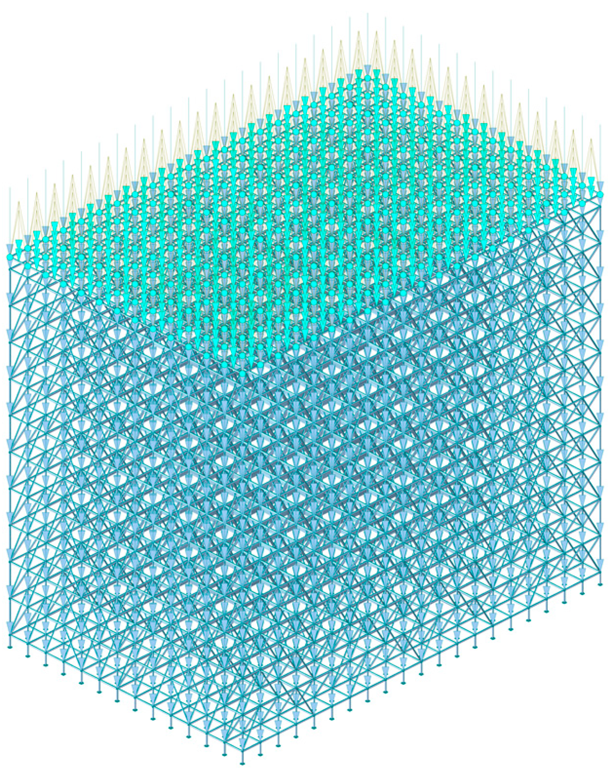
2.4. Loading Conditions

In accordance with the load specification and safety technical specification, a multi-level load system including permanent load and variable load is established. The standard value, combination modes and partial coefficient are determined accordingly. Based on the load effect combination theory, the partial coefficient method is applied to determine the load case. The basic combination is G1 + G2 + G3 + Q1 + Q3, where G1 is the self-weight of the scaffold, G2 is the self-weight of the template, G3 is the self-weight of the concrete, Q1 is the construction live load, and Q3 is the wind load. In the finite element model, the self-weight of the scaffold is applied along the Z-direction with a coefficient of −1, while the remaining loads are applied in their respective directions. The specific load values are shown in Table 3. The schematic diagram of loading conditions is shown in Figure 5.

3. Validation

This study utilizes the environmental random vibration excitation method to determine the dynamic characteristics of the scaffold system at the engineering site. The engineering reliability of the numerical model is validated through comparison with the measured modal parameters. The test system consists of integrated circuit piezoelectric (ICP) acceleration sensors and a Coca-Card data acquisition instrument from the eastern United States. The sampling interval were set at 0.01 s, corresponding to a sampling frequency of 100 Hz and the sampling time is 600 s. Based on the structural dynamic response characteristics and on-site construction layout conditions, measuring points are arranged in key sensitive areas: (1) joints connecting the vertical bar with the horizontal bar; (2) joints connecting the vertical bar with diagonal braces; (3) joints connecting the vertical bar with the vertical bar; (4) joints connecting the adjustable base with the vertical bar. The specific layout position is shown in Figure 6.
To effectively extract the modal parameters from the structural response under ambient excitation, the natural frequency of the scaffold is determined through the Stochastic Subspace Identification (SSI) method. The first four natural frequencies of the scaffold system were successfully obtained. The natural frequency results of the actual stochastic subspace identification of the scaffold are shown in Figure 7. The abscissa represents the frequency value and the ordinate represents the system order. The first four natural frequencies of the actual scaffold are 0.95 Hz, 1.02 Hz, 1.05 Hz and 1.13 Hz, respectively.
Figure 8 presents the acceleration time history response of the scaffold structure during the first 10 s under natural working conditions, as recorded by acceleration sensors. The signal predominantly exhibits low-frequency oscillations with continuous and nearly periodic waveforms. The peak acceleration is approximately ±0.04 m/s2, indicating a steady-state response under minor structural vibrations. No abrupt changes or noticeable trends are observed throughout the period, suggesting that the structure was not subjected to significant disturbances or impact excitations. The vibration response is dominated by low-frequency components, which are preliminarily attributed to the excitation of lower-order structural modes under natural stimuli such as wind loads or minor construction activities.
Based on the eigenvalue analysis function in MIDAS GEN 2021, the subspace iteration method was employed to calculate and extract the first four natural frequencies and mode shapes of the numerical model. A comparative analysis was then conducted between the simulated natural frequencies and the field measurements obtained from acceleration sensors. The results are presented in Table 4.
As shown in Table 4, the minimum error between the calculated value of the finite element model and the measured result is 2.72%, the maximum error is 5.00%, the average error is 3.50%, and the root mean square error is 3.61%. The natural frequencies obtained from the finite element model analysis are basically consistent with the actual structure, indicating that the numerical model and its analysis results have strong credibility.
Figure 9 is the natural vibration mode diagram corresponding to the first two modes. Figure 9a shows the first-order modal shape diagram of the scaffold structure. From the overall deformation pattern, it can be observed that the top level of the scaffold exhibits significant bending deformation, forming a downward concave shape. The deformation is concentrated at the top free end, while the deformation of the bottom fixed constraint area is small. Figure 9b shows the second-order natural vibration mode of the scaffold. The structure mainly shows bending deformation in local areas, especially near the middle and upper parts. Compared with Mode 1, this mode has the characteristics of more local components participating in bending deformation.

4. Results and Discussion

4.1. Key Parameters Sensitivity Analyses

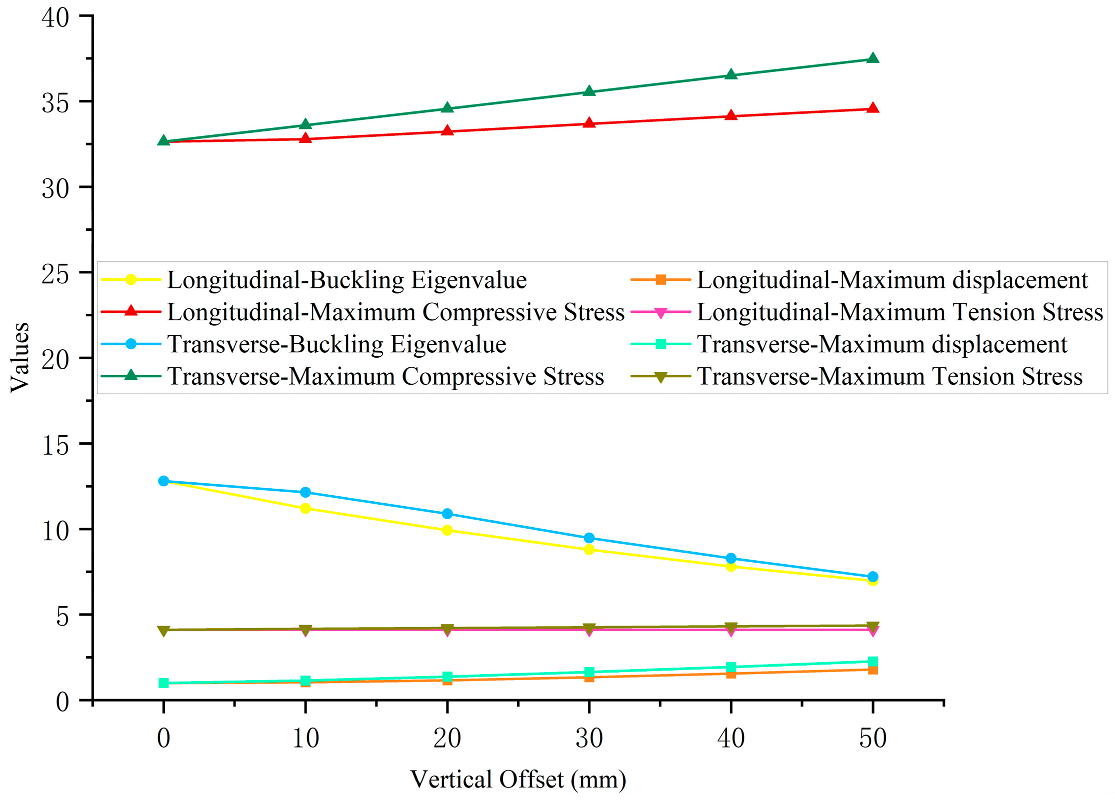
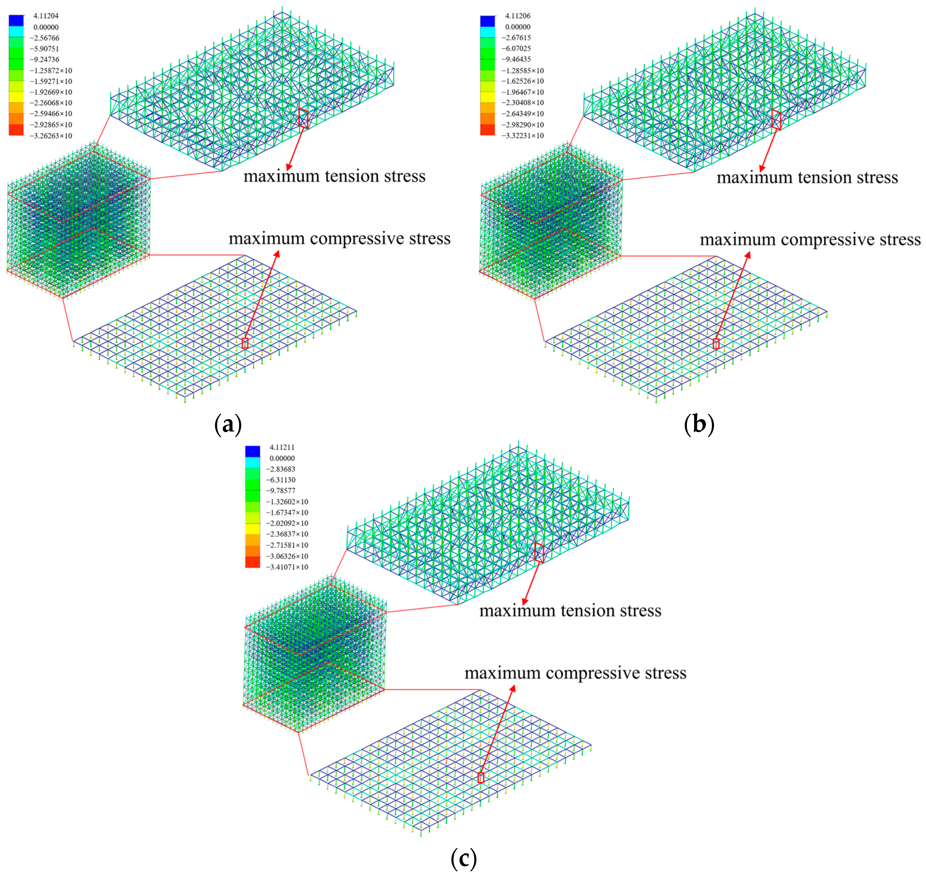
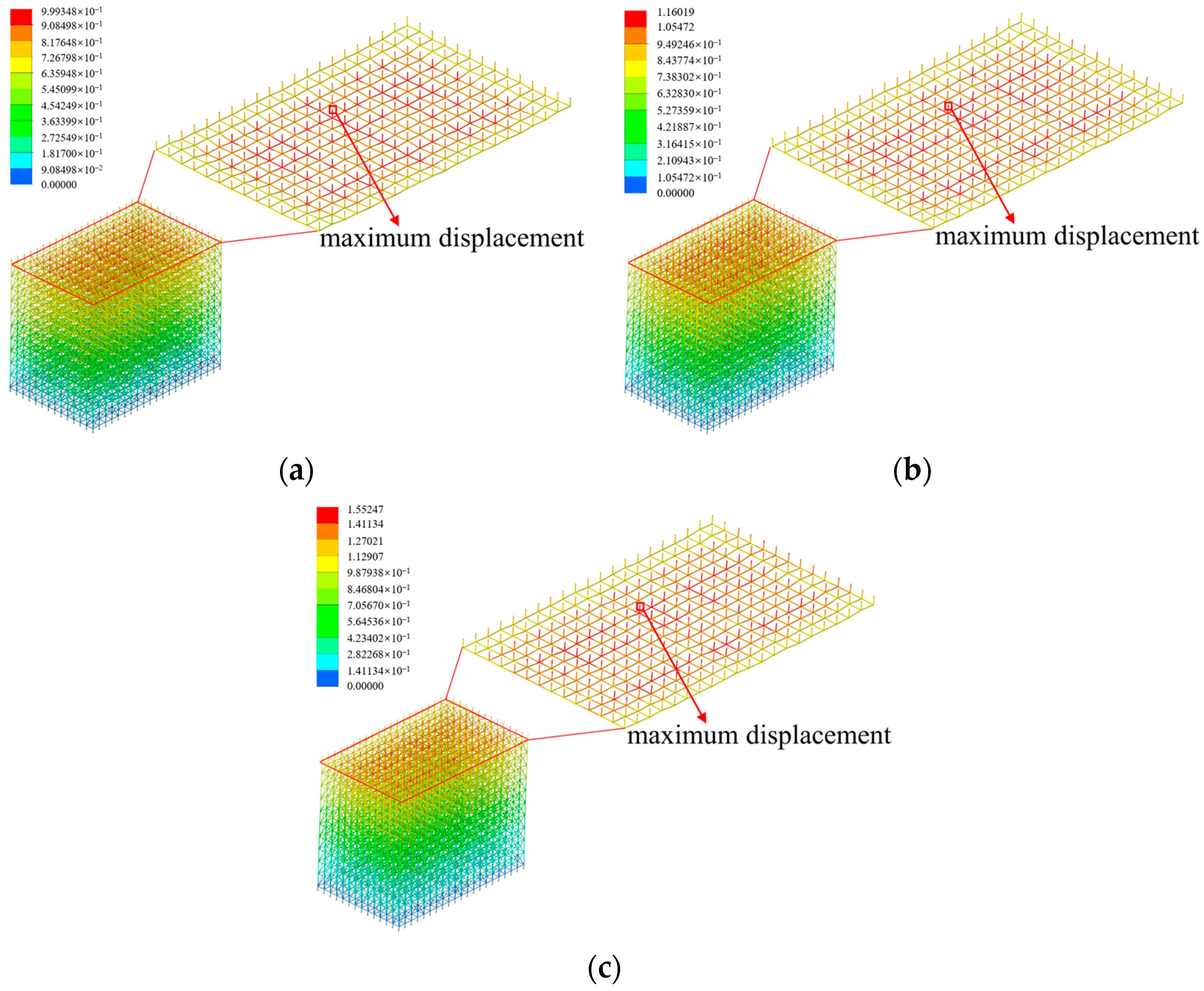
4.1.1. Bars Offset Magnitude

The bar offset degree comprehensively characterizes the verticality and horizontality offset characteristics of the scaffold system. When the offset degree exceeds the permissible threshold, it leads to a reconstruction of the structural stress system and the uneven distribution of stress, which will significantly compromise the overall stability of the structure. Figure 10 shows the longitudinal and transverse elevations of the scaffold. The model was constructed in accordance with standard specifications, and no bar offset is present.
To investigate the effects of the vertical offset and horizontal offset on the overall stability of the scaffold system, a single-factor control method was adopted to independently adjust the offset of each bar. Offset was applied along both the longitudinal and transverse directions of the scaffold, as illustrated in Figure 11. Vertical offset refers to the misalignment of vertical bars, resulting in a lack of perpendicularity to the ground, as shown in Figure 11a. Horizontal offset refers to the misalignment of horizontal bars, leading to non-parallel alignment with the ground, as shown in Figure 11b.
To analyze the effect of vertical offset independently, a step increment of 10 mm was used, and the stability of the scaffolding system was systematically evaluated within the deviation range of 0 mm to 50 mm. For the analysis of horizontal deviation, a smaller increment of 1 mm was applied, with the deviation range set between 0 mm and 5 mm.
The buckling eigenvalue is the core index to characterize the overall stability of the scaffold system, which plays a key role in key load prediction, buckling mode identification, and overall stability evaluation of structure. Therefore, this study characterizes the influence of verticality offset on the stability of the scaffold system via buckling eigenvalue, extreme value of tension and compression stress of members and extreme value of joint displacement. The specific numerical results are shown in Figure 12.
As shown in Figure 12, the buckling eigenvalue of the scaffold system is 12.80 under the reference condition without offset. With the application of verticality offsets in both the longitudinal and transverse directions, the buckling eigenvalue of the scaffold system exhibits a pronounced decreasing trend as the offset magnitude increases. The buckling eigenvalue decreases to 6.97 under 50 mm longitudinal offset condition, representing a 45.55% reduction compared to the reference condition without offset. The buckling eigenvalue decreases to 7.21 under the 50 mm transverse offset condition, representing a 43.67% reduction compared to the reference condition without offset. Under identical offset conditions, the decrease in the buckling eigenvalue caused by the longitudinal offset is 1.88 percentage points greater than that caused by the transverse offset. It shows that the detrimental impact of longitudinal verticality offset on scaffold stability is more significant compared to that of the transverse offset. Therefore, three working conditions with longitudinal verticality offsets of 0 mm, 20 mm, and 40 mm were selected to numerically analyze the stress distribution characteristics of the scaffold system. The stress cloud diagram is shown in Figure 13.
As shown in Figure 13, the stress distribution characteristics of the scaffold system under varying longitudinal verticality offset conditions are as follows: The maximum tensile stress is primarily concentrated in the diagonal braces area at the top layer of the scaffold system. The maximum compressive stress is mainly concentrated at the adjustable base at the bottom of the scaffold system. These results indicate that the longitudinal verticality offset exerts no significant influence on the spatial distribution characteristics of the compressive stress extreme value within the scaffold system. Under three kinds of longitudinal verticality offset conditions, the maximum tensile stress in the scaffold system is 4.11 N/mm2, while the corresponding maximum compressive stress is 32.63 N/mm2, 33.22 N/mm2, 34.11 N/mm2, respectively. The results indicate a weak dependence between the longitudinal vertical offset and the maximum tensile stress in the scaffold system. With the increase in longitudinal verticality offset, the maximum tensile stress remains relatively constant, while the maximum compressive stress exhibits a linear increase. The results indicate that the maximum compressive stress in the scaffold system is more sensitive to the longitudinal verticality offset than the maximum tensile stress.
Figure 14 shows the distribution characteristics of displacement of scaffold under three kinds of longitudinal verticality offset conditions. The joints with maximum displacement are concentrated in the vertex area of the adjustable bracket at the top of the scaffold system. It is noteworthy that the position of the maximum displacement joint shifts from the center toward the edge area with the increase in the longitudinal verticality offset. The maximum joint displacements in the scaffold system under the three longitudinal verticality offset conditions are 1.00 mm, 1.16 mm, and 1.55 mm, respectively. Under a longitudinal verticality offset condition of 40 mm, the nodal maximum displacement in the scaffold system is 1.55 mm, representing a 55.0% increase compared to the reference condition without offset. The scaffold system exhibits a significant positive correlation between the extreme value of the joint displacement and the longitudinal verticality offset. The maximum displacement of the joints in the scaffold system continues to increase with the increase in the longitudinal verticality offset.
To investigate the horizontal offset effect, the offset interval is set to 0–5 mm with 1 mm as the incremental gradient in the longitudinal and transverse directions, respectively. The calculation results are shown in Table 5. Under the reference condition without offset, the buckling eigenvalue is 12.80. The buckling eigenvalue of the scaffold system remains relatively constant under the condition of longitudinal and transverse horizontal offset. Concurrently, the extreme value of the joint displacement, the tensile and compressive stress of the scaffold system demonstrate negligible fluctuations. The analytical results show that the overall stability of the scaffold is not significantly affected in the range of 1–5 mm horizontality offset.
The analysis results show that the overall stability deterioration effect caused by the verticality offset of the scaffold system is more significant.

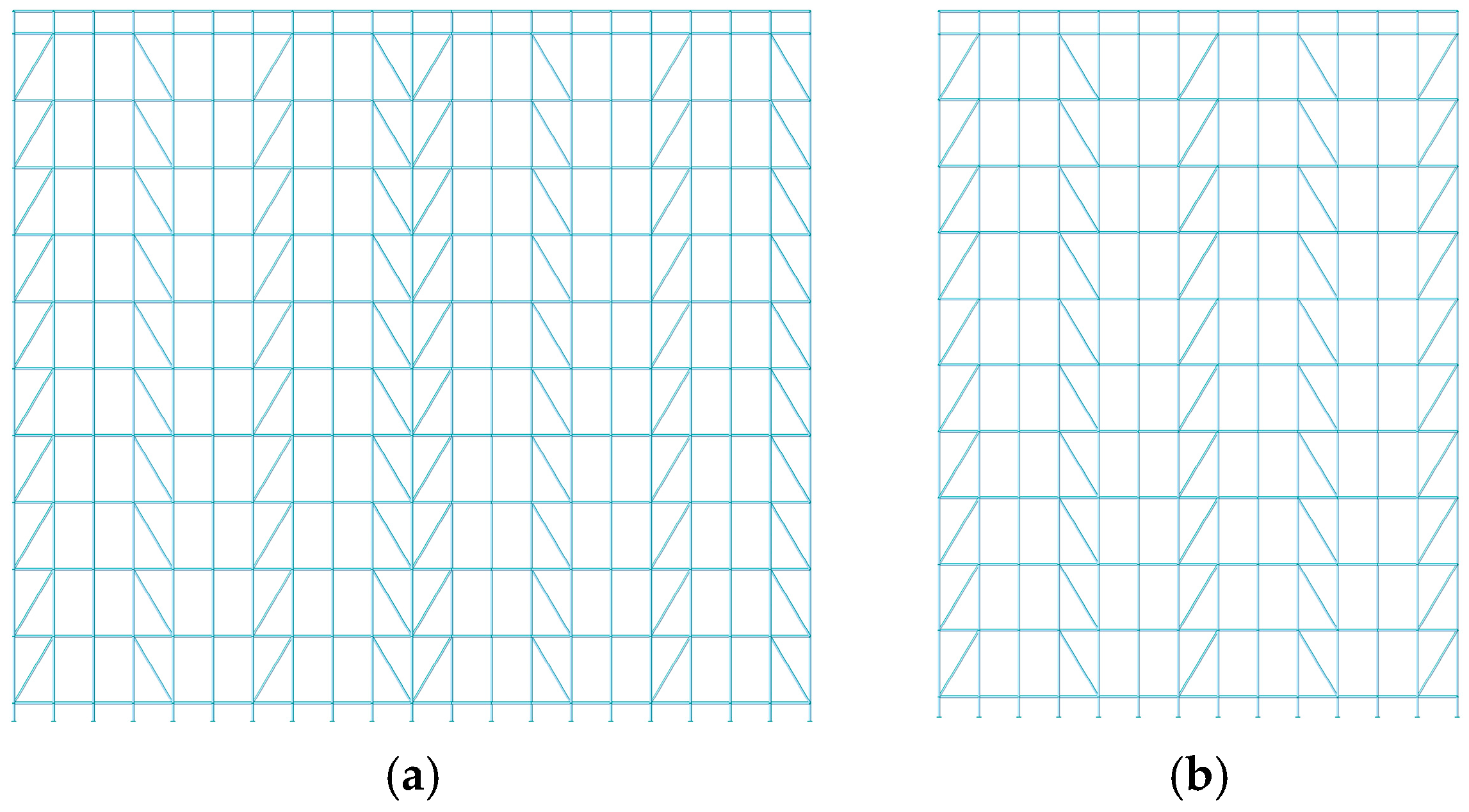
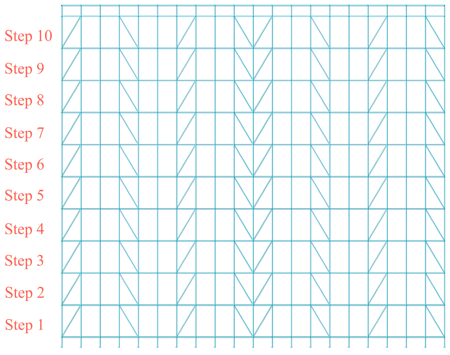
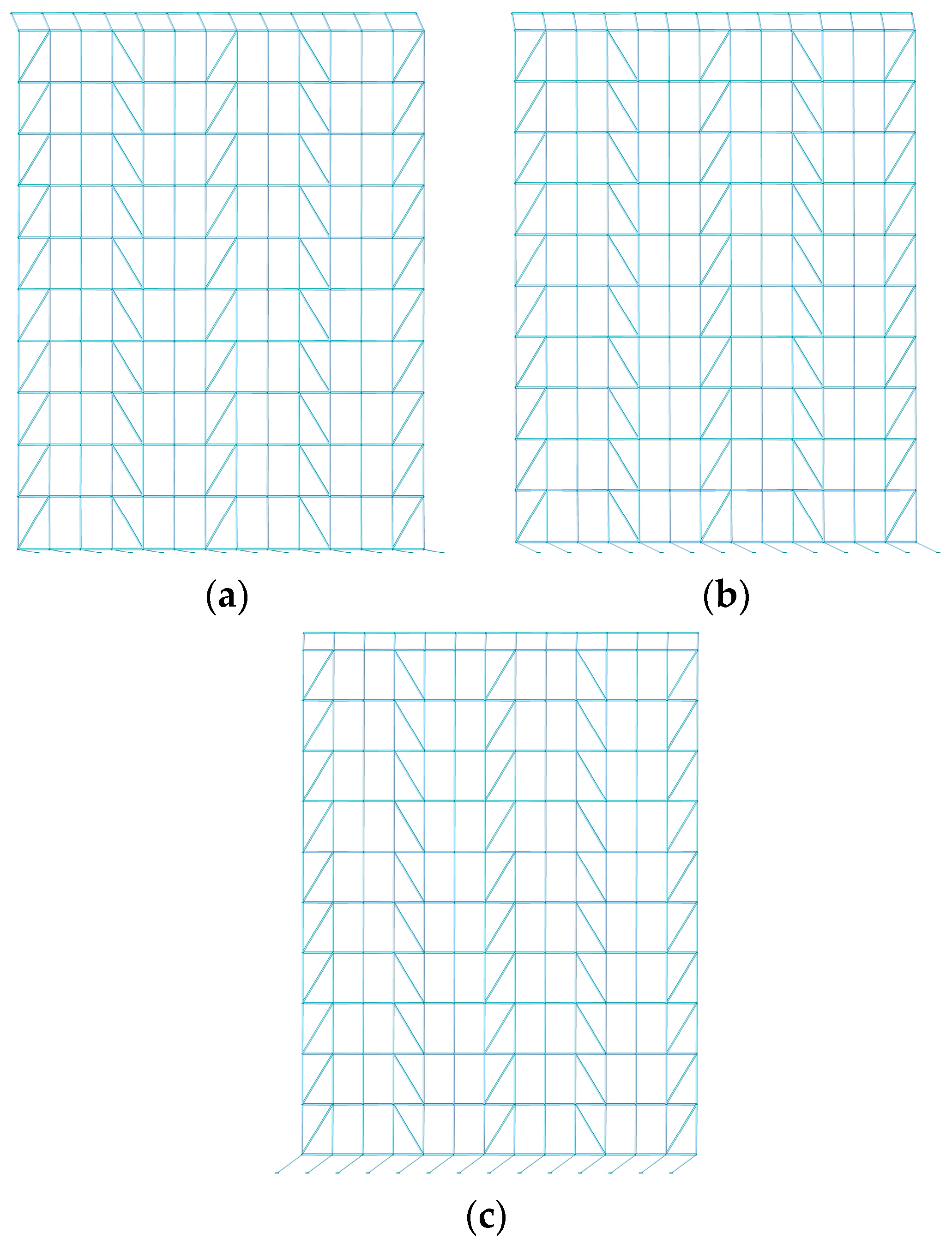
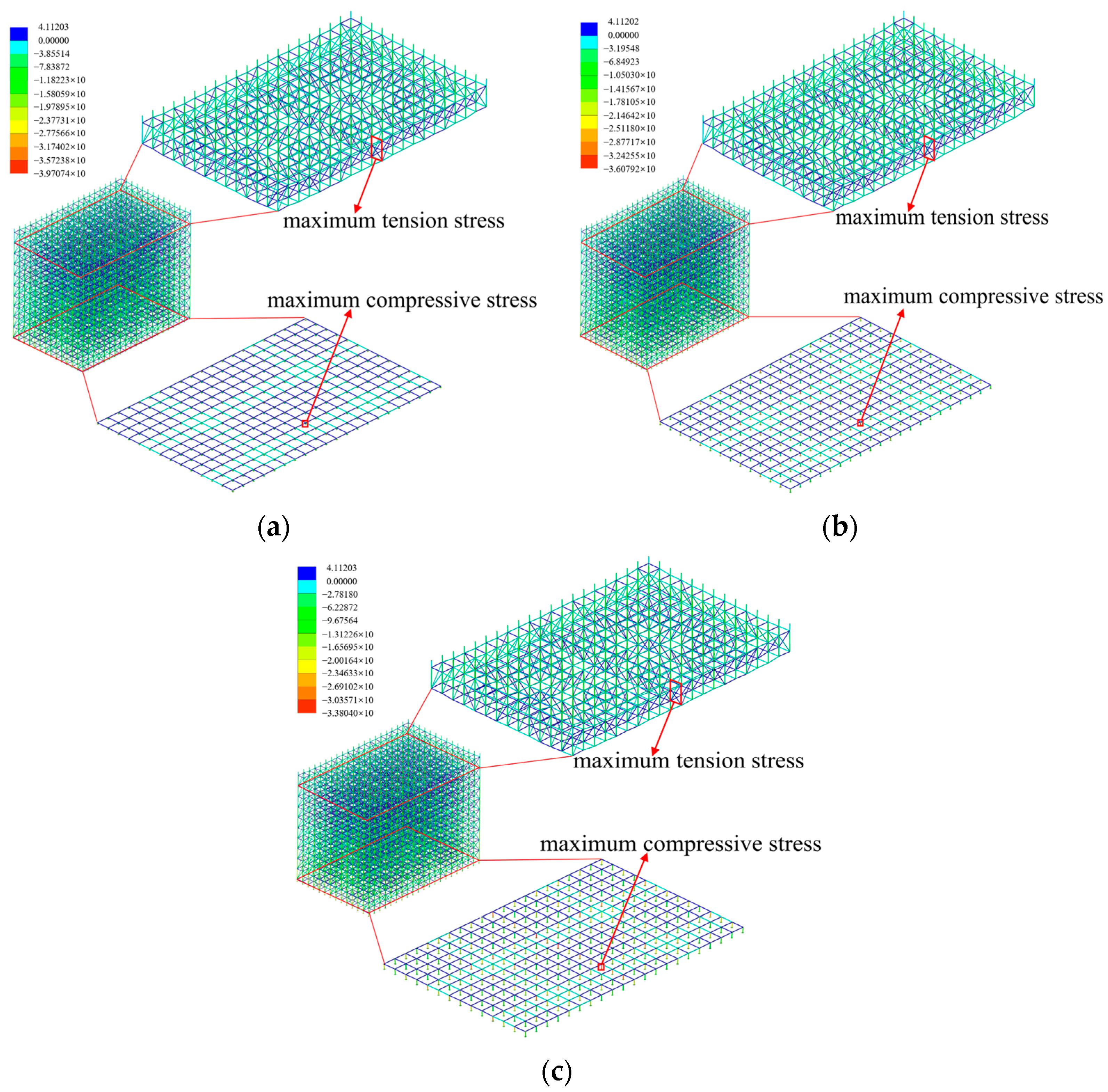
4.1.2. Layout of Diagonal Braces

To quantify the mechanical properties degradation of scaffold system caused by the absence of diagonal braces, two typical diagonal braces absence conditions are set based on the finite element numerical model under the reference condition, which are the whole step absence of diagonal braces and the whole columns absence of diagonal braces.
To investigate the influence of the whole step absence of diagonal braces on the stability of the scaffold system, the diagonal braces step-loss mode is set: the scaffold structure model consists of ten layers, also referred to as ten steps. Each step corresponds to the set of diagonal braces arranged at a specific layer. From the bottom to the top, the layers are defined as the first through tenth layers, and the diagonal braces at each respective layer are referred to as Step 1 through Step 10, as shown in Figure 15.
The finite element simulations were conducted to analyze the progressive absence process of the diagonal brace members from the first step to the tenth step. The extreme value of the tension, compression stress and the joint displacement and the buckling eigenvalue of the scaffold system under various working conditions were calculated to analyze the influence of the whole step absence of diagonal braces on the overall stability of scaffold system. The calculation results are shown in Figure 16.
The data in Figure 16 show that the buckling eigenvalue of the scaffold system is 12.80 under the complete reference condition of the diagonal braces system. Under the absence of the 10th step diagonal braces, the buckling eigenvalue is 6.32, representing a 50.63% reduction compared to the reference condition. As the position of the absent diagonal braces moves from the 10th step to the 1st step, the buckling eigenvalue increases first and then decreases. The buckling eigenvalue is 2.37 under the absence of the 1st step diagonal braces, which is 81.48% lower than the reference condition. These results indicate that the bottom diagonal braces make the most substantial contribution to the overall stability of the scaffold system. The analysis of Figure 16 shows that the integrity of the bottom and the top first step diagonal brace plays a decisive role in the stability of the scaffold system. Therefore, the two working conditions of the first step and the tenth step of the diagonal brace absence were selected to analyze the stress distribution characteristics of the scaffold system. The stress cloud diagram is shown in Figure 17.
As shown in Figure 17, the compressive stress distribution characteristics of the scaffold system under the condition of the whole step absence of diagonal brace are as follows: the maximum compressive stress is concentrated in the adjustable base at the bottom of the scaffold system, indicating that the absence of diagonal braces exerts no significant influence the spatial distribution characteristics of the compressive stress extreme value. The distribution characteristics of the maximum tensile stress are as follows: under the absence of the first step diagonal braces, the maximum tensile stress is concentrated in the diagonal brace area of the top layer of the scaffold system. The absence of the 10th step diagonal braces leads to a downward shift in the maximum tensile stress position, which is concentrated in the 9th step diagonal braces area in the upper part of the scaffold system. Under the conditions involving the absence of two different diagonal braces steps, the maximum tensile stress of the scaffold members is 4.11 N/mm2 and 4.12 N/mm2 respectively, while the maximum compressive stress is 24.18 N/mm2 and 32.31 N/mm2 respectively. The maximum tensile stress of the scaffold members is 4.11 N/mm2 and the maximum compressive stress is 32.63 N/mm2 under the reference condition with all diagonal brace intact. The maximum compressive stress under the two conditions involving the absence of different diagonal braces steps is reduced by 25.90% and 0.98%, respectively, compared with that under the reference condition. This indicates that the absence of diagonal braces can effectively reduce the maximum compressive stress of the scaffold members. However, the maximum tensile stress of the scaffold members under the condition of the absence of the diagonal braces changes by less than 1% compared with the reference condition, which indicate that the absence of the diagonal braces is weakly dependent with the maximum tensile stress of the scaffold members.
Figure 18 shows the displacement distribution characteristics of scaffold under the two conditions involving the absence of different diagonal braces steps. The maximum displacement joints are concentrated in the vertex area of the adjustable bracket at the top of the scaffold system. This indicates that the absence of the whole step of the diagonal braces exerts no significant influence on the spatial distribution of the maximum displacement joints of the scaffold. Under the reference condition with all diagonal braces intact, the maximum nodal displacement in the scaffold system is 1.00 mm. The maximum displacement of the joints under the two kinds of diagonal brace absence conditions are 1.01 mm and 0.99 mm, respectively. The changing range is less than 5% compared with the maximum displacement of the joints under the reference condition. The results indicate that the absence of diagonal braces has no significant correlation with the maximum nodal displacement of the scaffold system.
To investigate the influence of the whole columns absence of diagonal braces on the stability of the scaffold system, the diagonal brace column-loss mode is set. Figure 19 is a schematic diagram of the diagonal brace members marked in sequence in the scaffold system. The 1–8 and A–E in the figure correspond to a whole column of diagonal brace members perpendicular to the ground from the bottom to the top of the scaffold system.
Based on the principle of vertical and horizontal symmetrical arrangement, finite element simulations were conducted to analyze the progressive absence process of the diagonal brace member from the middle to both ends. The extreme value of the tension, the compression stress, the joint displacement, and the buckling eigenvalue of the scaffold system under various working conditions were calculated to analyze the influence of the diagonal braces absence with different sequence combinations on the overall stability of the scaffold system. The calculation results are shown in Table 6.
The data in Table 6 show that when the transverse sequence of the diagonal brace is missing at the same position, the buckling eigenvalue decreases first and then increases as the longitudinal sequence of the diagonal brace is missing from the middle to both ends. When the longitudinal sequence of the diagonal braces is missing at the same position, the buckling eigenvalue decreases first and then increases as the transverse bracing sequence is missing from the middle to both ends. The buckling eigenvalue is 12.80 under the reference condition with all diagonal braces intact. Among the longitudinal and transverse column sequence–diagonal brace combined absence condition, the smallest buckling eigenvalue among the combinations is 10.54 under the condition of B, D columns + 2, 7 columns, representing a 17.66% reduction compared to the reference condition. Additionally, among the combined working condition, if and only if the longitudinal 2, 7 columns are missing, the buckling eigenvalue is less than that of the diagonal brace under the reference condition with all diagonal brace intact. The data in Table 6 shows that the vertical 2, 7 columns and the horizontal B, D columns have a higher contribution to the overall stability. Therefore, the combination of diagonal braces columns absence is selected as C columns + 2, 7 columns, B, D columns + 2, 7 columns, A, E columns + 2, 7 columns. The numerical calculation is carried out to analyze the stress distribution characteristics of the scaffold system. The stress cloud diagram is shown in Figure 20.
As shown in Figure 20, the maximum compressive stress is concentrated in the adjustable base at the bottom of the scaffold system, indicating that the absence of diagonal braces exerts no significant influence on the spatial distribution of the maximum compressive stress. Under the combination absence condition of A, E columns + 2, 7 columns, the maximum tensile stress is concentrated at the horizontal bars at the bottom of the scaffold system. The maximum tensile stress is concentrated in the diagonal braces area of the top layer of the scaffold system under the combination absence condition of C columns + 2, 7 columns and B, D columns + 2, 7 columns. Under the three types of the column sequence–diagonal brace combination absence conditions, the maximum tensile stresses of the scaffold members are 3.28 N/mm2, 3.90 N/mm2, 4.16 N/mm2, and the maximum compressive stresses are 33.97 N/mm2, 25.75 N/mm2, 31.21 N/mm2. The maximum tensile stress of the scaffold members is 4.11 N/mm2 and the maximum compressive stress is 32.63 N/mm2 under the reference condition with all diagonal brace intact. Under the combination of diagonal brace–column absence condition of A, E + 2, 7, the maximum compressive stress increases by 4.11% compared with the reference condition. Inversely, under the combination of diagonal braces columns absence condition of C + 2, 7 and B, D + 2, 7, the maximum compressive stress decrease by 21.08% and 4.35%, respectively. Compared with the reference condition with all diagonal braces intact, the maximum tensile stress increases by 1.22% under the absence conditions of B, D columns + 2, 7 columns. Inversely, the maximum tensile stress decreases by 20.19% and 5.11%, respectively, under the other two conditions. It shows that the spatial position combination of the diagonal brace missing has a significant impact on the mechanical performance of the scaffold system. Especially when the missing diagonal brace is located at the intersection of columns B and D with columns 2 and 7, it induces a pronounced stress concentration effect on the key components of the system.
Figure 21 shows the displacement distribution characteristics: the maximum displacement joints are concentrated in the vertex area of the adjustable bracket at the top of the scaffold system. The position of the maximum displacement joint changes in a small range on the top floor of the scaffold under the combination condition of the absence of three kinds of a diagonal brace in the whole columns. The maximum nodal displacement in the scaffold system is 1.00 mm under the reference condition. The maximum displacements of the joints under the combination condition of three kinds of diagonal braces absence in the whole columns are 1.12 mm, 1.72 mm and 0.98 mm, respectively. Under a longitudinal verticality offset condition of 40 mm, the nodal maximum displacement in the scaffold system is 1.55 mm, representing a 55.0% increase compared to the reference condition without offset. When the combination of diagonal braces columns is B, D columns + 2, 7 columns, the maximum displacement of the joints in the frame is 1.72 mm, which is 72% higher than the maximum displacement of the joints under the reference condition.
According to the comprehensive analyses found in Table 6 and Table 7, the integrity of the bottom step and the top step diagonal brace as well as the diagonal brace of vertical 2, 7 columns and horizontal B, D columns play a decisive role in the stability of the scaffold system.

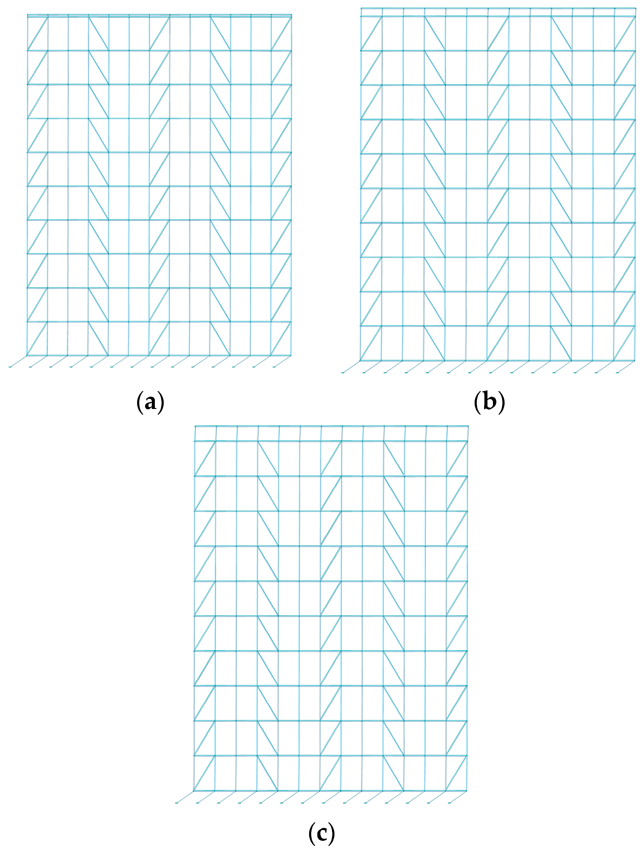
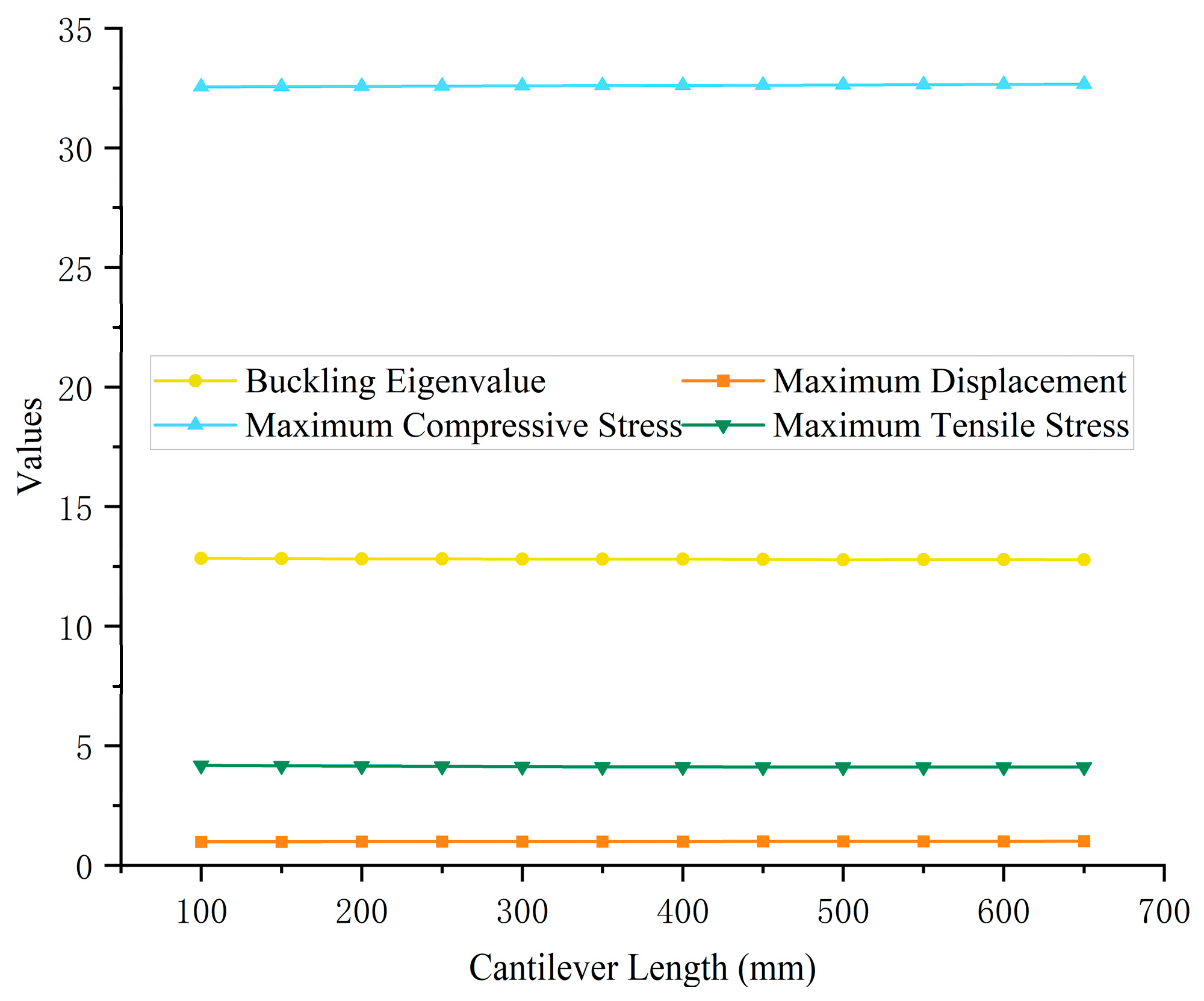
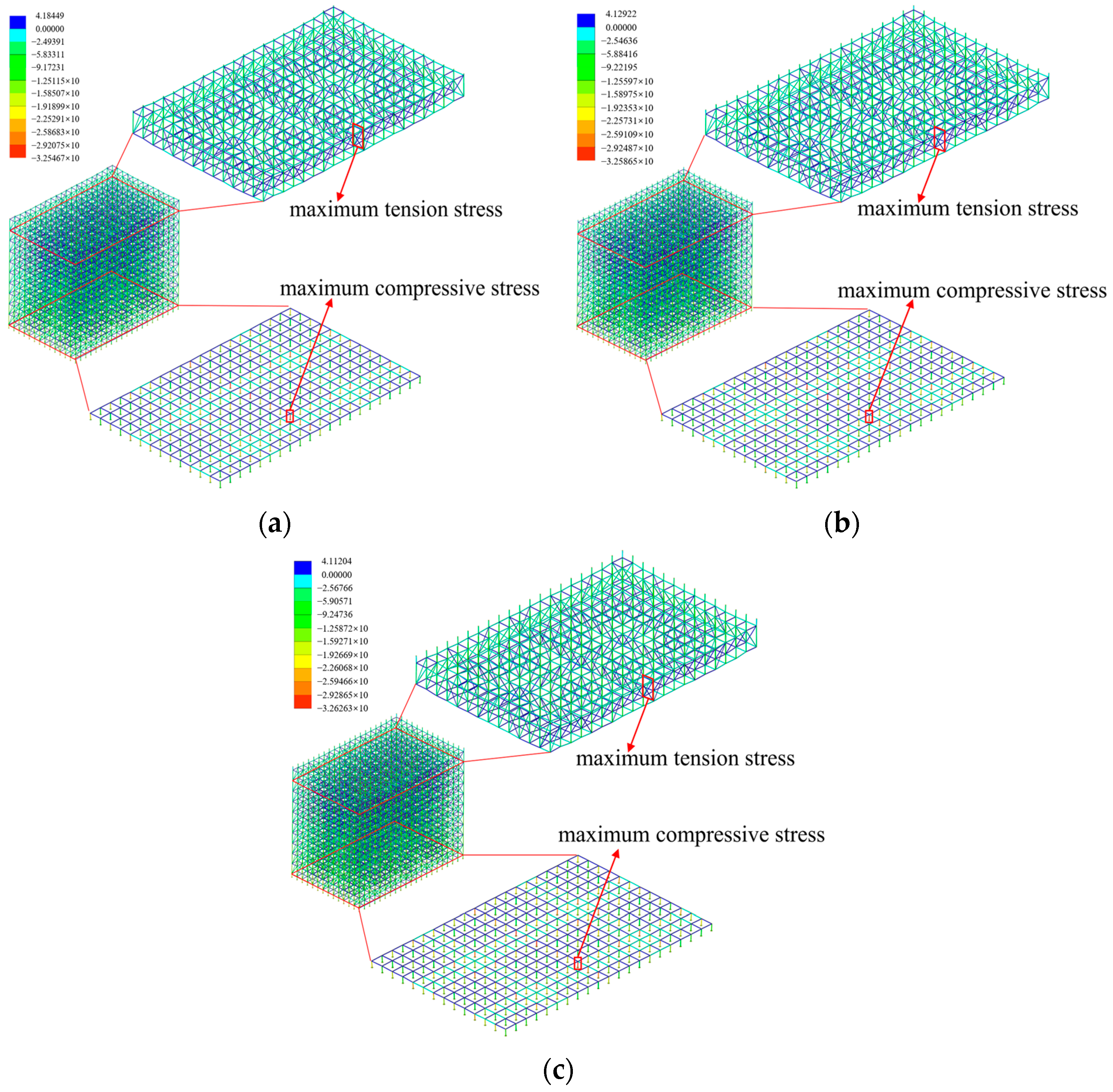
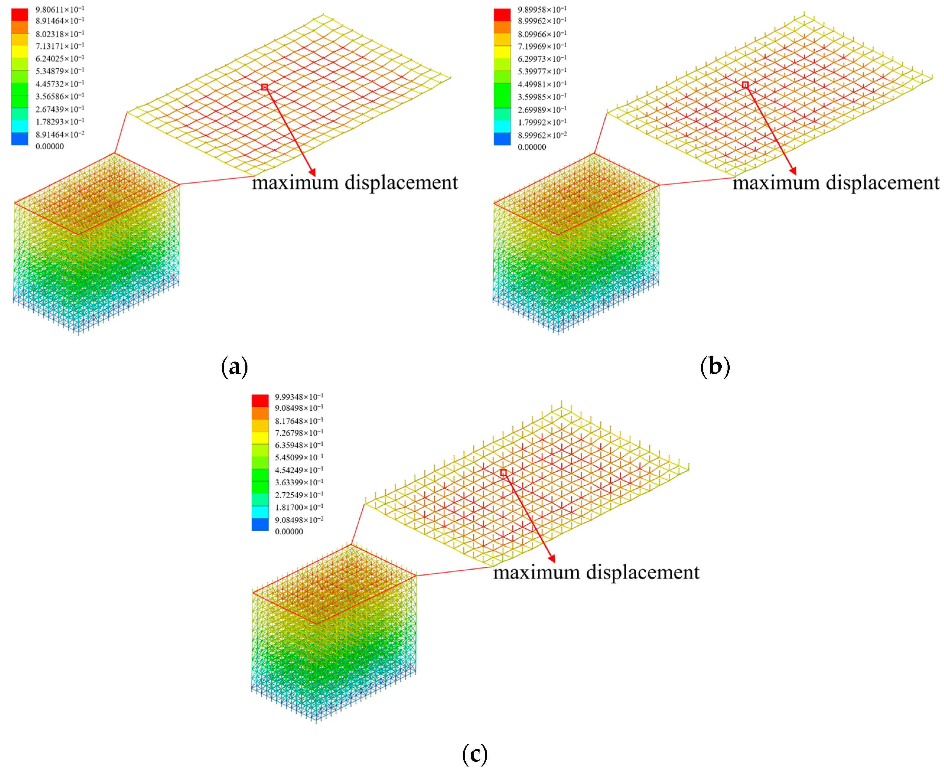
4.1.3. Adjustable Bracket Cantilever Length

The cantilever length of the adjustable brace is a key control parameter for the safety of the scaffold system, which directly affects the static balance, dynamic response and failure mode of the structure. To quantify the influence of the cantilever length variations in the adjustable bracket on the overall stability of the scaffold system, the working conditions of the adjustable bracket under 12 different cantilever lengths are set based on the finite element numerical model under the reference working condition. The unit mode is shown in Figure 22.
Using a parametric modeling approach, the stability evolution law of the scaffold system is systematically investigated within the range of 100–650 mm cantilever length with 50 mm as the incremental gradient. The buckling eigenvalue of the scaffold system, the extreme value of the tension and compression stress of the member and the extreme value of the joint displacement under various working conditions are calculated. The overall stability of the scaffold system under different cantilever length conditions is analyzed. The specific calculation results are shown in Figure 23.
The data in Figure 23 show that when the cantilever length of the adjustable brace increases from 100 mm to 650 mm, the buckling eigenvalue of the scaffold system only decreases from 12.84 to 12.78, representing a reduction of 0.47%. Meanwhile, the vertical displacement increases from 0.98 mm to 1.01 mm, with an increase of 3.06%. Existing studies have demonstrated that the increase in cantilever length can induce localized buckling deformation of the cantilever end, resulting in the eccentric compression of the upright rod, which significantly weakens the stability of the scaffold system. Therefore, three working conditions with adjustable cantilever lengths of 100 mm, 300 mm, and 500 mm are selected to analyze the stress distribution characteristics of scaffold system. The stress cloud diagram is shown in Figure 24.
As shown in Figure 24, the maximum tensile stress is concentrated in the diagonal braces area of the top layer of the scaffold system, while the maximum compressive stress is concentrated in the adjustable base at the bottom of the scaffold system. This indicates that the variations in the cantilever length of the adjustable bracket have no significant effect on the spatial distribution of tensile and compressive stress extremum of the scaffold system. Under three conditions with adjustable bracket cantilever lengths of 100 mm, 300 mm, and 500 mm, the maximum tensile stress in the scaffold members gradually decreases from 4.18 N/mm2 to 4.11 N/mm2, with a decrease of 1.67%. Adversely, the maximum compressive stress increased linearly from 32.55 N/mm2 to 32.63 N/mm2, with an increase of 0.25%. The quantitative relationship shows that the cantilever length parameter is negatively correlated with the tensile stress extreme value of the scaffold system, and positively correlated with the compressive stress extreme value.
Figure 25 shows the joint displacement distribution characteristics of the scaffold system under three conditions with varying adjustable bracket cantilever length. The maximum displacement joints are distributed in the vertex area of the adjustable bracket at the top of the scaffold system, indicating that the change in adjustable bracket cantilever length has no significant effect on the spatial distribution of the maximum displacement joints of the scaffold. The three maximum joint displacement conditions with varying adjustable bracket cantilever length are 0.98 mm, 0.99 mm, and 1.00 mm, respectively. It can be seen that with the increase in adjustable bracket cantilever length, the maximum joint displacement in the scaffold system shows a monotonically increasing trend, indicating that the adjustable bracket cantilever length is positively correlated with the maximum joint displacement in the scaffold system.

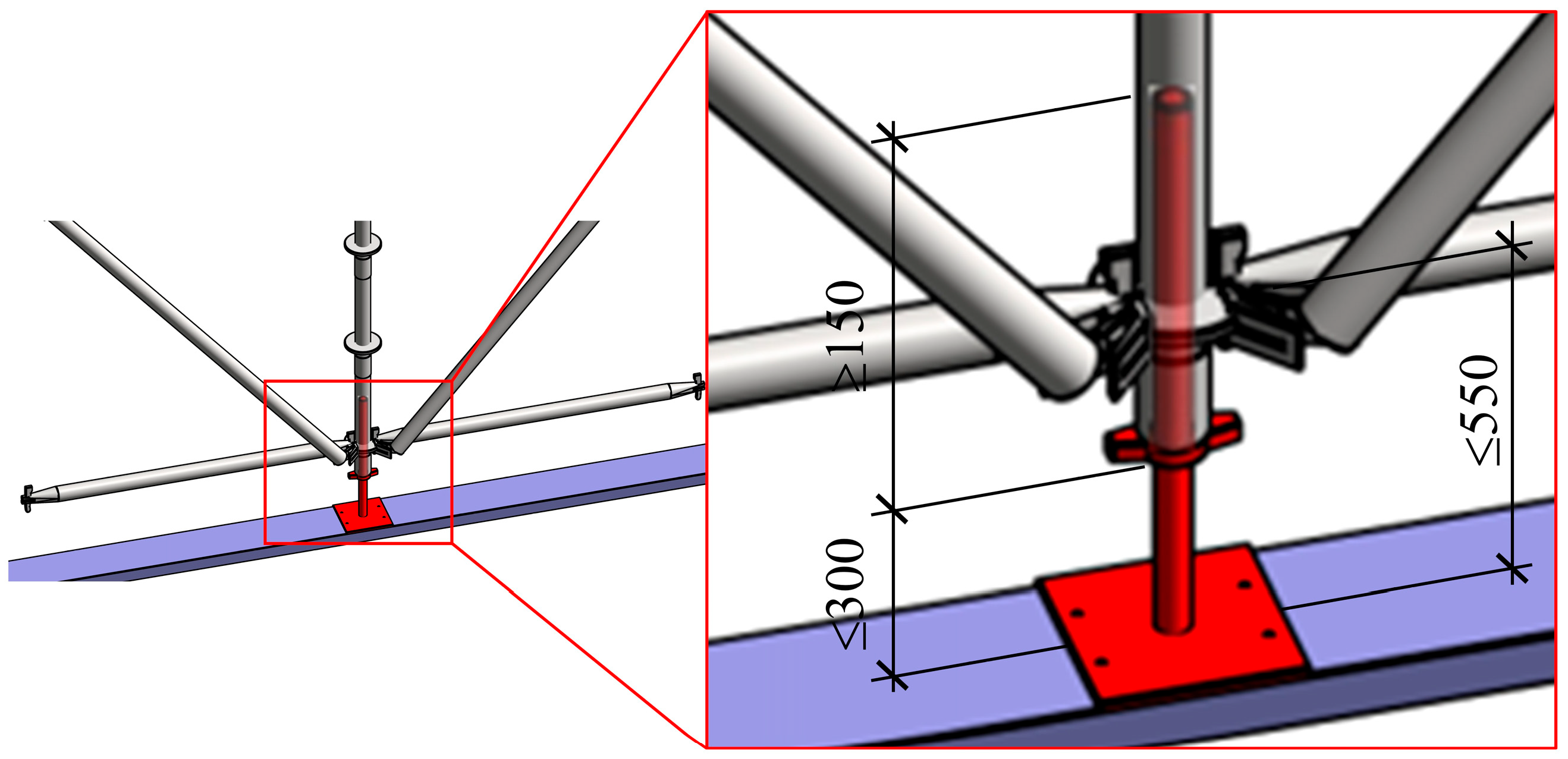
4.1.4. Adjustable Base Height

The height of the adjustable base is a key control parameter during the installation of the scaffold system, which is defined as the vertical distance from the bottom of the sweeping rod to the ground. This component, in conjunction with the bottom horizontal bars and vertical bars, forms an integrated spatial structural system, thereby enhancing the overall stiffness of the scaffold. To solve the problem of the adjustable base height differences caused by the uneven foundation in the construction site and to quantify the influence of the adjustable base height change on the overall stability of the scaffold system, 10 different adjustable base height conditions are set based on the finite element numerical model under the reference condition. The unit mode is shown in Figure 26.
Using a parametric modeling approach, the stability evolution law of the socket scaffold system in the height range of 100–550 mm adjustable base with 50 mm as the incremental gradient is systematically investigated. The buckling eigenvalue of the scaffold system, the extreme value of the tension and compression stress of the member and the extreme value of the joint displacement under various working conditions are calculated. The overall stability of the scaffold system under different adjustable base height conditions is analyzed. The specific calculation results are shown in Figure 27.
The data in Figure 27 show that as the adjustable base height increases from 100 mm to 350 mm, the buckling eigenvalue of the scaffold system increases from 10.75 to 14.33, with an increase of 33.30%. This suggests a substantial enhancement in the overall structural stability. However, when the adjustable base height exceeds 350 mm, the buckling eigenvalue of the scaffold system decreases from 14.33 to 11.59, with a decrease of 19.12%, thereby indicating a significant deterioration in overall stability. These findings demonstrate that the scaffold system exhibits optimal overall stability when the adjustable base height is 350 mm. With the adjustable base height increasing, the buckling eigenvalue of the scaffold system shows a nonlinear change trend, which increases first and then decreases. The change trend is shown in Figure 27.
Three working conditions with adjustable base heights of 100 mm, 250 mm and 400 mm were selected for numerical analysis of the stress distribution characteristics of the scaffold system. The stress cloud diagram is shown in Figure 28.
As shown in Figure 28, the stress distribution characteristics of the scaffold system under varying height adjustable base conditions are as follows: the maximum tensile stress is concentrated in the diagonal braces area of the top layer of the scaffold system, and the maximum compressive stress is concentrated in the adjustable base at the bottom of the scaffold system. This indicates that variations in adjustable base height have no significant impact on the spatial distribution of tensile and compressive stress extrema. Under three varying adjustable base height conditions, the maximum tensile stress of scaffold members remains consistent at approximately 4.11 N/mm2, while the maximum compressive stress is 39.10 N/mm2, 36.08 N/mm2 and 33.80 N/mm2 respectively. This indicates that the adjustable base height exhibits a weak correlation with the maximum tensile stress of the scaffold members, which remain largely unaffected. Adversely, the maximum compressive stress gradually decreased from 39.10 N/mm2 to 33.80 N/mm2, with a decrease of 13.55%, indicating that the adjustable base height was negatively correlated with the maximum compressive stress of the scaffold system.
Figure 29 shows the joint displacement distribution characteristics of the scaffold system under three varying adjustable base height conditions. The maximum displacement joints are distributed in the vertex area of the adjustable bracket at the top of the scaffold system, indicating that the variations in the adjustable base height have no significant impact on the spatial distribution of the maximum joint displacement in the scaffold system. The quantitative analysis shows that the maximum joint displacement under three varying adjustable base height conditions are 0.96 mm, 0.97 mm and 0.99 mm, respectively. This indicates that the maximum joint displacement of the scaffold system continues to increase with the increase in the adjustable base height, suggesting a positive correlation between the adjustable base height and nodal displacement extremum.

4.2. Establishment of Early Warning Mechanism for Frame Instability

4.2.1. Weight Analysis of Key Parameters

This study employs an orthogonal test design method to construct a multi-parameter coupling sensitivity analysis framework, which quantify the significance level of each parameter’s influence on the overall stability of scaffold system. The orthogonal test design theory selects representative test points through orthogonal tables (denoted as Ln(ab)) and replaces the full-factor test with a uniform distribution and comparable sample combination to achieve efficient analysis of multi-factor and multi-level systems. Based on the results of finite element buckling analysis, this study quantifies the sensitivity differences in five key parameters on the scaffold stability by the range method, including adjustable base height, adjustable bracket cantilever length, diagonal braces arrangement, verticality offset and horizontality offset. Each parameter is set at 4 levels, with the variation in the corresponding buckling eigenvalues required to exhibit a clear and regular trend. Furthermore, the level-setting rules for all key parameters were kept consistent to ensure comparability, as detailed in Table 7. The weight ranking of each key parameter’s influence on the scaffold stability is determined using the buckling eigenvalue as the core evaluation index.
Based on the five-parameter and four-level parameter framework outlined in Table 7, the L16(54) orthogonal array is employed to construct the multi-factor interaction test matrix. The missing positions of diagonal braces members refer to the configurations illustrated in Figure 7 and Figure 10.
Through the orthogonal array mapping mechanism, the integration of each parameter level combination is realized, thereby establishing the orthogonal test scheme of scaffold stability. The specific parameter combinations are shown in Table 8.
Based on the theoretical framework of orthogonal test design, and ignoring the interaction effect between the key parameters, a parameter sensitivity evaluation system is established using the classical range analysis method. To quantitatively assess the sensitivity level of each critical parameter, three core evaluation indicators were defined, including: comprehensive response of parameter level Ti, mean response ti and range Ri. The calculation results are shown in Table 9.
The range Ri is a key index to characterize the sensitivity of parameters, and its value is significantly positively correlated with the influence weight on the bearing capacity of the scaffold system. A larger Ri value indicates a more significant control effect of the key parameter on the scaffold system’s bearing capacity of. As shown in Table 9, the range values for the adjustable base height, adjustable bracket cantilever length, diagonal brace arrangement, verticality offset and horizontality offset are 0.62, 0.54, 4.25, 2.35, and 0.57, respectively. These results indicate that the influence weight of the five key parameters on the scaffold stability from high to low is the lack of bracing, verticality offset of the vertical bar, the adjustable base height, the horizontality offset of the horizontal bar, and adjustable bracket cantilever length.

4.2.2. Determination of Compliance Testing Indicators

There are significant differences in the sensitivity of the overall stability of the scaffold system to key parameters. Therefore, targeted compliance detection indicators are established for key parameters with different sensitivity levels.
The current technical specifications stipulate that the configuration mode of the diagonal brace for scaffold systems with a standard step of 1.5 m should be comprehensively determined according to the erection height, the frame type, and the design axial force of the vertical members. The diagonal brace layout for scaffold systems with different frame types should comply with the requirements specified in Table 10 and Table 11. For the scaffold system exceeding 16 m in height, diagonal braces must be continuously arranged across the entire span within the top step of the scaffold.
Based on the conclusion drawn in Section 4.1.2, the diagonal braces located at the bottom, top, and ends of the scaffold system contribute significantly to the overall structural stability. Therefore, a dual-index detection system is proposed for the absence of diagonal braces, incorporating both position sensitivity and early warning levels. The classification criteria for the early warning levels are shown in Figure 30. Specifically, the absence of the first diagonal brace at either the bottom or top of the scaffold triggers a red warning level. The yellow warning level corresponds to the absence of diagonal braces in 50% of the scaffold system bottom region, while the blue warning level indicates a similar loss in 50% of the top region. A green level denotes a fully intact bracing configuration. Within each warning level, the system is further divided into core areas and edge areas based on the spatial distribution of diagonal braces. The core area refers to the central 50% region measured from the centerline and is classified as secondary priority (Level 2), while the edge area refers to the outer 50% region and is classified as primary priority (Level 1).
According to the current technical specifications, the inserted depth of the adjustable base screw into the vertical bar should not be less than 150 mm, the exposed length of the screw should not exceed 300 mm, and the distance between the center line of the sweeping rod and the base plate should not exceed 550 mm, as shown in Figure 31.
When the height of the adjustable base does not exceed 350 mm, the overall stability of the scaffold system has no significant deterioration trend. However, once the height of the adjustable base exceeds 350 mm, the stability of the scaffold system shows a nonlinear attenuation characteristic. In conjunction with the current technical specifications, the early warning levels for both the adjustable base height and the exposed length of the screw are determined, as shown in Table 12.
According to current technical specifications, the adjustable bracket cantilever length should not exceed 650 mm, the exposed length of the adjustable bracket screw should not exceed 400 mm, and the inserted depth of the vertical bar or the double-slot support beam should not be less than 150 mm, as shown in Figure 32.
An excessive adjustable bracket cantilever length tends to induce the coupling effect of local buckling deformation and eccentric compression of the vertical bar, which significantly reduces the overall stability of the scaffold system. In conjunction with the current technical specifications, the early warning levels of the adjustable bracket cantilever length and the exposed length of the screw are determined, as shown in Table 13.
According to current technical specifications, the verticality control index of the vertical bar is governed by a dual-criteria approach. It must satisfy the verticality limit of H/500 mm (H is the erection height) while simultaneously ensuring that the vertical offset does not exceed 50 mm, with an allowable deviation of ±5 mm. Additionally, the horizontal offset limit of the horizontal bar is ±5 mm. With the increase in verticality offset, the overall stability of the scaffold system decreases significantly. Adversely, the overall stability of the scaffold system remains largely unaffected within the horizontal offset range of ±5 mm. In conjunction with the current technical specifications, the warning levels for verticality and horizontality offset are determined, as shown in Table 14.

5. Conclusions

In this study, a multi-parameter coupled numerical model was established to comprehensively investigate the stability evolution mechanisms of scaffold systems under multi-parameter coupling effects. The influence mechanism of adjustable base height, adjustable bracket cantilever length, layout of diagonal braces, verticality and horizontality offset on the stability of scaffold is systematically explored through nonlinear buckling analysis and eigenvalue sensitivity analysis. The principal conclusions are as follows:
(1)
With the adjustable base height increasing, the overall stability of the scaffold system shows a nonlinear change trend, which increases first and then decreases. The scaffold system exhibits optimal overall stability when the adjustable base height is 350 mm. In contrast, the overall stability of the scaffold system remains relatively constant within the range of 100–650 mm adjustable bracket cantilever length.
(2)
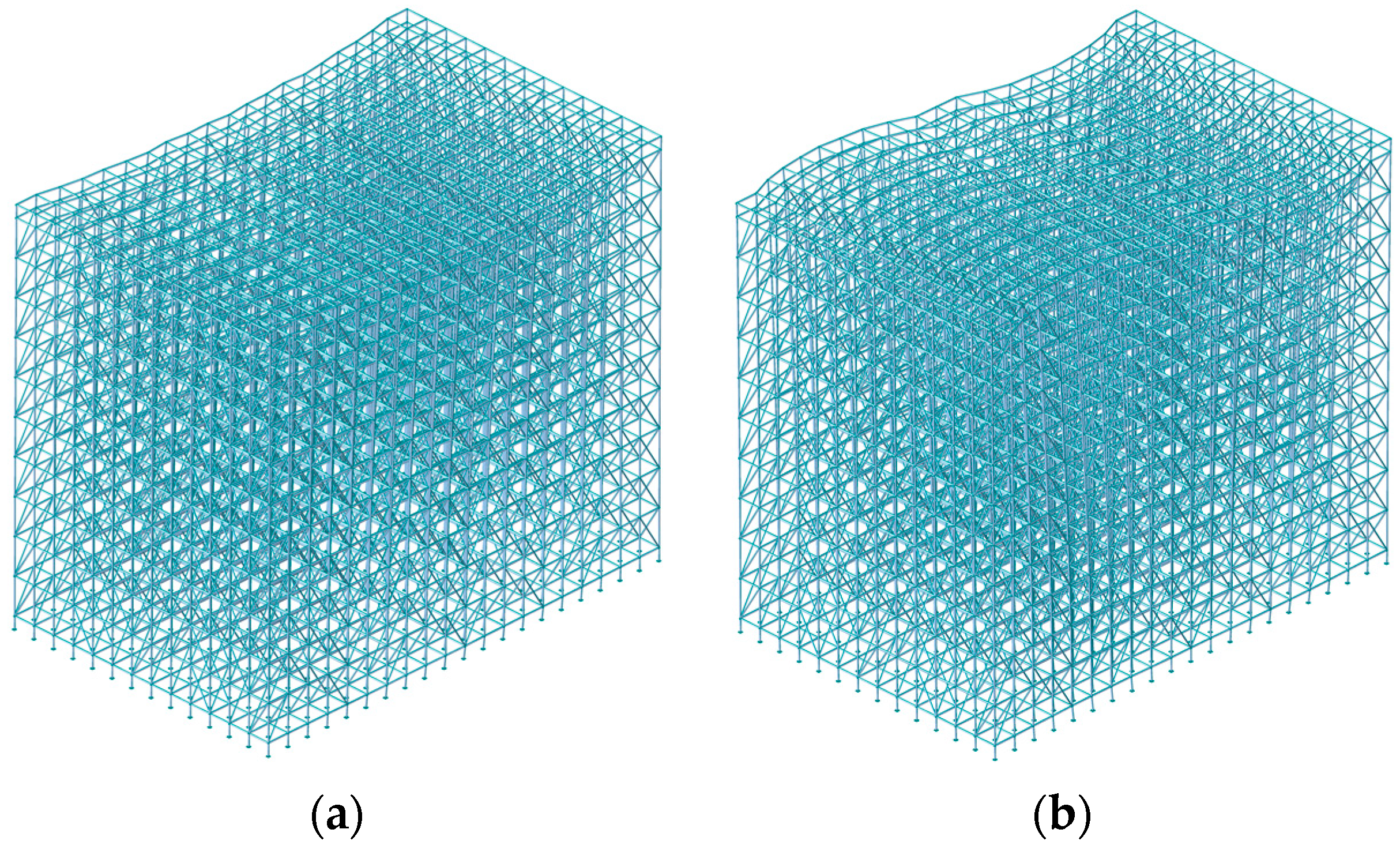
The overall stability of the scaffold system demonstrates pronounced sensitivity to the absence of diagonal braces. The absence of the diagonal braces located at the bottom, top, and ends of the scaffold system induces a significant attenuation of the overall stability, and the maximum buckling eigenvalue decreases by 81.45%. The overall stability of the scaffold system decreases significantly with the increase in the verticality offset, while the horizontality offset within the range of ±5 mm exhibits negligible influence on the overall stability of the scaffold system.
(3)
The results of orthogonal test and range analysis indicate that the influence weight of the five key parameters on the scaffold stability from high to low is the lack of bracing, verticality offset of the vertical bar, adjustable base height, horizontality offset of the horizontal bar, and adjustable bracket cantilever length.
(4)
The working conditions of the key parameters that trigger a red warning for the scaffold system are as follows: absence of the first-step diagonal brace at either the bottom or top of the scaffold; an adjustable base height less than 150 mm or an exposed screw length exceeding 300 mm; an adjustable bracket cantilever length exceeding 650 mm or an exposed screw length exceeding 400 mm; a verticality offset exceeding 50 mm; or a horizontal offset exceeding 5 mm or a verticality exceeding H/500.

Author Contributions

Conceptualization, P.W.; methodology, P.W., G.Y. and Y.Y.; software, G.Y.; validation, G.Y. and Y.Y.; formal analysis, P.W.; investigation, P.W.; resources, H.Q.; data curation, G.Y.; writing—original draft preparation, G.Y.; writing—review and editing, P.W. and Y.Y.; visualization, G.Y.; supervision, Y.Y.; project administration, Y.Y.; funding acquisition, P.W. All authors have read and agreed to the published version of the manuscript.

Funding

This work was supported by Key Technologies and Applications for Intelligent Monitoring and Assessment of Construction Scaffolding Safety by Chongqing Special Program for Technological Innovation and Application Development (Grant CSTB2022TIAD-KPXO137), Chongqing Urban Rail Express Line Full Life Cycle CIM Technology Application Research and Demonstration Research Project by Ministry of Housing and Urban-Rural Development Technology Demonstration Project (Grant No. 2022-S-062) and Chongqing Urban Railway Express Digital Construction Method and Control Research Project by Chongqing Construction Science and Technology Plan Project (Grant City Section 2023 No. 5-1).

Data Availability Statement

The data presented in this study are available on request from the corresponding author.

Conflicts of Interest

The authors declare no conflicts of interest.

References

  1. Kim, J.; Kim, J.; Kim, Y.; Kim, H. 3D Reconstruction of Large-Scale Scaffolds with Synthetic Data Generation and an Upsampling Adversarial Network. Autom. Constr. 2023, 156, 105108. [Google Scholar] [CrossRef]
  2. Al-Sadoon, Z.A.; Barakat, S.; Abed, F.; Ateyat, A.A. Stability of Structural Steel Tubular Props: An Experimental, Analytical, and Theoretical Investigation. Steel Compos. Struct. 2023, 49, 143–159. [Google Scholar]
  3. Hu, X.; Peng, G.; Niu, D.; Fan, Y. Experimental Study on Mechanical Properties of Steel Tube-Coupler Connections in Corroded Scaffolds. J. Constr. Steel Res. 2021, 176, 106383. [Google Scholar] [CrossRef]
  4. Li, H.Z.; Liu, Z.; Miao, J.Y. The Investigation of Stability Analysis of Tube and Coupler Scaffold. Adv. Mat. Res. 2012, 594–597, 730–733. [Google Scholar] [CrossRef]
  5. Chuang, K.-Y.; Tserng, H.-P. A Study of Automated Intelligent Monitoring of Scaffolding Safety for Construction Projects. J. Chin. Inst. Eng. 2024, 47, 626–642. [Google Scholar] [CrossRef]
  6. Zhang, N.; Qiu, R.; Zhao, Z.; Zhao, B.; Wang, S. Influence of Random Geometrical Imperfection on Loading Capacity of Scaffold Based on Stochastic Numerical Model. Adv. Eng. Software 2024, 197, 103737. [Google Scholar] [CrossRef]
  7. Cimellaro, G.P.; Domaneschi, M. Stability Analysis of Different Types of Steel Scaffolds. Eng. Struct. 2017, 152, 535–548. [Google Scholar] [CrossRef]
  8. Nowobilski, T.; Hoła, B. Methodology Based on Causes of Accidents for Forcasting the Effects of Falls from Scaffoldings Using the Construction Industry in Poland as an Example. Saf. Sci. 2023, 157, 105945. [Google Scholar] [CrossRef]
  9. Dogan, E.; Yurdusev, M.A.; Yildizel, S.A.; Calis, G. Investigation of Scaffolding Accident in a Construction Site: A Case Study Analysis. Eng. Fail. Anal. 2021, 120, 105108. [Google Scholar] [CrossRef]
  10. Li, X.; Guo, Y.; Ge, F.; Yang, F. Human Reliability Assessment on Building Construction Work at Height: The Case of Scaffolding Work. Saf. Sci. 2023, 159, 106021. [Google Scholar] [CrossRef]
  11. Yu, W.K.; Chung, K.F.; Chan, S.L. Structural Instability of Multi-Storey Door-Type Modular Steel Scaffolds. Eng. Struct. 2004, 26, 867–881. [Google Scholar] [CrossRef]
  12. Kim, H.; Lee, Y.; Won, J.-H.; Jeong, S.-C.; Kim, S. Investigation of the Global Structural Behavior of the Prefabricated Shoring System Considering Structural Details. Buildings 2023, 13, 494. [Google Scholar] [CrossRef]
  13. Mercier, C.; Khelil, A.; Al Mahmoud, F.; Blin-Lacroix, J.-L.; Pamies, A. Experimental Investigations of Buckling Behaviour of Steel Scaffolds. Structures 2021, 33, 433–450. [Google Scholar] [CrossRef]
  14. Zhang, H.; Rasmussen, K.J.R.; Ellingwood, B.R. Reliability Assessment of Steel Scaffold Shoring Structures for Concrete Formwork. Eng. Struct. 2012, 36, 81–89. [Google Scholar] [CrossRef]
  15. Gao, H.; Gao, W.; Li, C.X.; Huo, X.X. Influence of the Structural Performance of Steel Tubular Scaffold Based on Measured Imperfection. Appl. Mech. Mater. 2012, 256–259, 754–757. [Google Scholar] [CrossRef]
  16. Peng, J.-L.; Wu, C.-W.; Chan, S.-L.; Huang, C.-H. Experimental and Numerical Studies of Practical System Scaffolds. J. Constr. Steel Res. 2013, 91, 64–75. [Google Scholar] [CrossRef]
  17. Jia, L.; Liu, H.; Chen, Z.; Liu, Y.; Wu, Y. Experimental Study on Bearing Capacity of Reinforced Steel Tubular Scaffold under Uniform Loads. Adv. Civ. Eng. 2019, 2019, 4324528. [Google Scholar] [CrossRef]
  18. Dong, J.; Liu, H.; Lei, M.; Fang, Z.; Guo, L. Safety and Stability Analysis of Variable Cross-Section Disc-Buckle Type Steel Pipe High Support System. Int. J. Press. Vessels Pip. 2022, 200, 104831. [Google Scholar] [CrossRef]
  19. Peng, J.-L.; Wang, S.-H.; Wang, C.-S. Stability Study on Scaffolds with Inclined Surfaces and Extended Jack Bases in Construction; The Hong Kong Institute of Steel Construction: Hong Kong, China, 2021; pp. 73–83. [Google Scholar]
  20. Zhang, C.; Yang, J.; Jiang, L.; He, Y. Experimental Studies and Finite Element Analysis of Socket-Type Keyway Steel Pipe Scaffolding. Buildings 2024, 14, 245. [Google Scholar] [CrossRef]
  21. Zhang, H.; Chandrangsu, T.; Rasmussen, K.J.R. Probabilistic Study of the Strength of Steel Scaffold Systems. Struct. Saf. 2010, 32, 393–401. [Google Scholar] [CrossRef]
  22. Zhao, Z.; Liang, B.; Li, S.; Qiu, R.; Gu, X.; Zhang, N. Buckling Capacity of Socket Template Scaffold with Random Bending Stiffness and Capacity. Structures 2025, 71, 108152. [Google Scholar] [CrossRef]
  23. Chan, J.L.Y.; Chan, S.-L.; Liu, Y.-P.; Liu, S.-W. Progressive Collapse of System Scaffolds with Accidental Removal of Bracing Members. J. Constr. Steel Res. 2024, 218, 108720. [Google Scholar] [CrossRef]
  24. Huang, H.; Peng, Z.; Hou, J.; Zheng, X.; Ding, Y.; Wu, H. Study on the Ultimate Load-Bearing Capacity of Disc Buckle Tall Formwork Support Considering Uncertain Factors. Buildings 2024, 14, 828. [Google Scholar] [CrossRef]
  25. Czepiżak, D.; Ramezantitkanloo, A.; Pieńko, M. Problems of monitoring critical elements of scaffolding. Arch. Civ. Eng. 2024, 70, 233–254. [Google Scholar]
  26. Sun, M.; Zhang, L.; Li, X.; Li, X.; Li, Q. Wind Load Analysis on Temporary Scaffolding Structures in High-Altitude Venues Based on Numerical Simulation: A Case Study From the 2022 Beijing Olympics. Adv. Civ. Eng. 2024, 2024, 3746675. [Google Scholar] [CrossRef]
  27. Pieńko, M.; Błazik-Borowa, E. Experimental Studies of Ringlock Scaffolding Joint. J. Constr. Steel Res. 2020, 173, 106265. [Google Scholar] [CrossRef]
  28. Yu, H.; Guo, S.; Liu, W.; Gao, R. Experimental Study on Stable Bearing Capacity of Wheel-Buckle Formwork Support Frames. Structures 2023, 48, 1175–1189. [Google Scholar] [CrossRef]
  29. Liu, H.; Jia, L.; Wen, S.; Liu, Q.; Wang, G.; Chen, Z. Experimental and Theoretical Studies on the Stability of Steel Tube–Coupler Scaffolds with Different Connection Joints. Eng. Struct. 2016, 106, 80–95. [Google Scholar] [CrossRef]
  30. Ilcik, J.; Arora, V.; Dolejs, J. Design of New Scaffold Anchor Based on the Updated Finite Element Model. Eng. Struct. 2016, 118, 334–343. [Google Scholar] [CrossRef]
  31. Liu, H.; Meng, Y.; Jia, L.; Chen, Z.; Liu, Q.; Wen, S. Structural Behavior of Steel Tube and Coupler Scaffolds with Stability Strengthening Details. Int. J. Steel Struct. 2018, 18, 79–95. [Google Scholar] [CrossRef]
  32. Li, P.; Chu, S.; Qin, S.; Ding, H.; Luo, N.; Yu, Y.; Zhang, T.; Xiong, G. Optimisation of Prestressed Stayed Steel Columns Based on Strengthen Elitist Genetic Algorithm. J. Constr. Steel Res. 2025, 227, 109324. [Google Scholar] [CrossRef]
  33. Kim, J.; Kim, J.; Koo, N.; Kim, H. Automating Scaffold Safety Inspections Using Semantic Analysis of 3D Point Clouds. Autom. Constr. 2024, 166, 105603. [Google Scholar] [CrossRef]
  34. Sakhakarmi, S.; Park, J.; Cho, C. Enhanced Machine Learning Classification Accuracy for Scaffolding Safety Using Increased Features. J. Constr. Eng. Manag. 2019, 145, 04018133. [Google Scholar] [CrossRef]
Figure 1. Scaffold application scenarios in marine engineering. (a) Ship engineering construction; (b) cross-sea bridge construction; (c) offshore platform construction (image source: https://www.vcg.com/; https://image.baidu.com/ (accessed on 6 April 2025)).
Jmse 13 01141 g001
Figure 2. Joint connection diagram.
Jmse 13 01141 g002
Figure 3. Scaffold numerical model.
Jmse 13 01141 g003
Figure 4. Boundary condition diagram. (a) Scaffold bottom constraint; (b) end constraints of component element.
Jmse 13 01141 g004
Figure 5. Loading conditions.
Jmse 13 01141 g005
Figure 6. Acceleration sensor position diagram.
Jmse 13 01141 g006
Figure 7. Vibration stability map of stochastic subspace identification.
Jmse 13 01141 g007
Figure 8. Time history of the acceleration (First 10 s, 100 Hz Sampling).
Jmse 13 01141 g008
Figure 9. Natural vibration mode diagram. (a) Mode 1; (b) Mode 2.
Jmse 13 01141 g009
Figure 10. Longitudinal and transverse facade drawings. (a) Longitudinal facade diagram; (b) transverse facade diagram.
Jmse 13 01141 g010
Figure 11. Schematic of structural member offset. (a) Verticality offset of bar; (b) horizontality offset of bar.
Jmse 13 01141 g011
Figure 12. Impact of verticality offset on scaffold.
Jmse 13 01141 g012
Figure 13. Scaffold stress cloud diagram under longitudinal vertical offset. (a) Verticality offset 0 mm; (b) longitudinal verticality offset 20 mm; (c) longitudinal verticality offset 40 mm.
Jmse 13 01141 g013
Figure 14. Scaffold displacement cloud diagram under longitudinal vertical offset. (a) Verticality offset 0 mm; (b) longitudinal verticality offset 20 mm; (c) longitudinal verticality offset 40 mm.
Jmse 13 01141 g014
Figure 15. Stepwise marking diagram for diagonal braces.
Jmse 13 01141 g015
Figure 16. Impact of whole step absence of diagonal braces on scaffold.
Jmse 13 01141 g016
Figure 17. Stress cloud diagram of scaffold under the whole step absence of diagonal braces. (a) Diagonal braces absence of step 1; (b) diagonal braces absence of step 10.
Jmse 13 01141 g017
Figure 18. Scaffold displacement cloud diagram under the whole step absence of diagonal braces. (a) Diagonal braces absence of step 1; (b) diagonal braces absence of step 10.
Jmse 13 01141 g018
Figure 19. Column-wise marking diagram for diagonal braces. (a) Longitudinal column-wise marking for diagonal brace; (b) transverse column-wise marking for diagonal brace; (c) plane column-wise marking for diagonal brace.
Jmse 13 01141 g019
Figure 20. Stress cloud diagram of scaffold under the whole columns absence of diagonal braces. (a) Diagonal braces columns absence combination A, E + 2, 7; (b) diagonal braces columns absence combination B, D + 2, 7; (c) diagonal braces columns absence combination C + 2, 7.
Jmse 13 01141 g020
Figure 21. Scaffold displacement cloud diagram under the whole columns absence of diagonal braces. (a) Diagonal brace and column absence combination A, E + 2, 7; (b) diagonal braces and column absence combination B, D + 2, 7; (c) diagonal brace and columns absence combination C + 2, 7.
Jmse 13 01141 g021
Figure 22. Modal diagram of scaffold units under varying adjustable bracket cantilever length conditions. (a) Cantilever length 100 mm; (b) cantilever length 350 mm; (c) cantilever length 650 mm.
Jmse 13 01141 g022
Figure 23. Impact of varying adjustable bracket cantilever length conditions on scaffold.
Jmse 13 01141 g023
Figure 24. Stress cloud diagram of scaffold under varying adjustable bracket cantilever length conditions. (a) Cantilever length 100 mm; (b) cantilever length 300 mm; (c) cantilever length 500 mm.
Jmse 13 01141 g024
Figure 25. Scaffold displacement cloud diagram under varying adjustable bracket cantilever length conditions. (a) Cantilever length 100 mm; (b) cantilever length 300 mm; (c) cantilever length 500 mm.
Jmse 13 01141 g025
Figure 26. Modal diagram of scaffold units under varying adjustable base height conditions. (a) Adjustable base height 100 mm; (b) adjustable base height 300 mm; (c) adjustable base height 550 mm.
Jmse 13 01141 g026
Figure 27. Impact of varying adjustable base height conditions on scaffold.
Jmse 13 01141 g027
Figure 28. Stress cloud diagram of scaffold under varying adjustable base height conditions. (a) Adjustable base height 100 mm; (b) adjustable base height 250 mm; (c) adjustable base height 400 mm.
Jmse 13 01141 g028
Figure 29. Scaffold displacement cloud diagram under varying adjustable base height conditions. (a) Adjustable base height 100 mm; (b) adjustable base height 250 mm; (c) adjustable base height 400 mm.
Jmse 13 01141 g029
Figure 30. The early warning level classification diagram for diagonal braces absence.
Jmse 13 01141 g030
Figure 31. Schematic of adjustable base height (unit: mm).
Jmse 13 01141 g031
Figure 32. Schematic of adjustable bracket cantilever length (unit: mm).
Jmse 13 01141 g032
Table 1. Steel parameters.
Parametric IndexData
Elastic Modulus (N/mm2)2.0600 × 105
Poisson’s Ratio0.3
Linear Expansion Coefficient (1/[F])6.6667 × 10−6
Volume Weight (N/mm3)7.85 × 10−5
Tension Strength (MPa)470
Yield Strength (MPa)235
Elongation Rate (%)26
Damping Ratio0.02
Table 2. Chemical composition table of Q235B.
MaterialComposition (%)
CMnSiPFe
Q235B0.130.490.200.030.04
Table 3. Load values.
Parametric IndexStandard Value (KN/m2)
Frame Weight G1Value According to the Actual Weight
Template Weight G20.5
Ordinary Beam or Slab Reinforced Concrete Self-weight G325.1
Construction Personnel and Equipment Load Q12.5
Wind Load Q30.276
Table 4. Comparison between model results and actual measurement results.
ModeNatural Frequency (Hz)Deviation
Numerical CalculationActual Measurement
10.920.953.26%
20.991.023.03%
31.001.055.00%
41.101.132.72%
Table 5. Impact of horizontality offset on scaffold.
Horizontality OffsetBuckling
Eigenvalue
Maximum
Displacement/mm
Maximum Compressive Stress/MPaMaximum Tensile Stress/MPa
012.801.0032.634.11
Longitudinal112.801.0032.634.11
212.801.0032.634.11
312.801.0032.634.11
412.801.0032.634.11
512.801.0032.634.11
Transverse112.801.0032.634.11
212.801.0032.634.11
312.801.0032.634.11
412.801.0032.634.11
512.801.0032.634.11
Table 6. Impact of whole column absence of diagonal braces on scaffold.
Horizontal
Absence
Position/Column
Longitudinal
Absence
Position/Column
Buckling
Eigenvalue
Maximum
Displacement/mm
Maximum
Compressive Stress/MPa
Maximum Tensile Stress/MPa
completecomplete12.801.0032.634.11
C4, 512.980.9726.664.07
3, 612.920.9831.024.15
2, 710.780.9831.214.16
1, 812.910.9831.114.14
B, D4, 512.861.7021.883.78
3, 612.821.7225.593.89
2, 710.541.7225.753.90
1, 812.801.7225.673.89
A, E4, 512.971.1029.163.11
3, 612.931.1233.763.11
2, 710.781.1233.973.28
1, 812.911.1233.852.82
Table 7. Key parameters and levels.
LevelKey Parameter
Base Height/mmCantilever Length/mmAbsence Position of Diagonal BracesVerticality Offset/mmHorizontality Offset/mm
1550650Step 1505
2500600Step 2404
3450550Step 3303
4400500Step 4202
Table 8. Orthogonal test design.
Level AssemblyBase Height/mmCantilever Length/mmAbsence Position of Diagonal BracesVerticality Offset/mmHorizontality Offset/mmBuckling
Eigenvalue
1550650Step 15051.29
2550600Step 24044.75
3550550Step 33035.42
4550500Step 42027.51
5500650Step 23025.82
6500600Step 12032.03
7500550Step 45044.41
8500500Step 34054.68
9450650Step 32047.05
10450600Step 43056.42
11450550Step 14021.62
12450500Step 25034.36
13400650Step 44035.52
14400600Step 35024.32
15400550Step 22057.22
16400500Step 13041.93
Table 9. Evaluation criteria for orthogonal tests.
Evaluation IndexesBase HeightCantilever LengthAbsence of Diagonal BracesVerticality OffsetHorizontality Offset
T118.9719.686.8714.3819.61
T216.9417.5222.1516.5718.14
T319.4518.6721.4719.5917.33
T418.9918.4823.8623.8119.27
t14.744.921.723.604.90
t24.244.385.544.144.54
t34.864.675.374.904.33
t44.754.625.975.954.82
Ri0.620.544.252.350.57
Table 10. Diagonal braces arrangement in standard-type (Type B) scaffold.
Design Axial Force of Vertical Bar N (KN)Scaffold Height H (m)
H ≤ 88 < H ≤ 1616 < H ≤ 2424 < H
N ≤ 25Every 3 spansEvery 3 spansEvery 2 spansEvery 1 span
25 < N ≤ 40Every 2 spansEvery 1 spanEvery 1 spanEvery 1 span
40 < NEvery 1 spanEvery 1 spanEvery 1 spanEvery span
Table 11. Diagonal braces arrangement in heavy-duty (Type Z) scaffold.
Design Axial Force of Vertical Bar N (KN)Scaffold Height H (m)
H ≤ 88 < H ≤ 1616 < H ≤ 2424 < H
N ≤ 40Every 3 spansEvery 3 spansEvery 2 spansEvery 1 span
40 < N ≤ 65Every 2 spansEvery 1 spanEvery 1 spanEvery 1 span
65 < NEvery 1 spanEvery 1 spanEvery 1 spanEvery span
Table 12. Early warning classification of adjustable base system.
Warning LevelAdjustable Base Height H1Exposed Screw Length L1
Red warning0 mm < H1 ≤ 150 mm300 mm < L1
Blue warning150 mm < H1 ≤ 350 mm
Green warning350 mm < H1 ≤ 450 mm0 mm < L1 ≤ 300 mm
Yellow warning450 mm < H1 ≤ 550 mm
Red secondary warning550 mm < H1
Table 13. Early warning classification of adjustable bracket system.
Warning LevelAdjustable Bracket Cantilever Length H2Exposed Screw Length L2
Green warning0 mm < H2 ≤ 300 mm0 mm < L2 ≤ 400 mm
Blue warning300 mm < H2 ≤ 500 mm
Yellow warning500 mm < H2 ≤ 650 mm
Red warning650 mm < H2400 mm < L2
Table 14. Early warning classification of bar offset.
Warning LevelVerticality Offset δ1Horizontality Offset δ2
Green warning0 mm < δ1 ≤ 10 mm0 mm < δ2 ≤ 5 mm
Blue warning10 mm < δ1 ≤ 30 mm
Yellow warning30 mm < δ1 ≤ 50 mm
Red warning50 mm < δ15 mm < δ2
(Note: Verticality > H/500 triggers a red warning).
Disclaimer/Publisher’s Note: The statements, opinions and data contained in all publications are solely those of the individual author(s) and contributor(s) and not of MDPI and/or the editor(s). MDPI and/or the editor(s) disclaim responsibility for any injury to people or property resulting from any ideas, methods, instructions or products referred to in the content.

