Article

Research on Power Conversion and Control Technology of Ocean Buoy Tidal Energy Power Supply System

School of Automation, Wuxi University, Wuxi 214105, China
*
Author to whom correspondence should be addressed.
J. Mar. Sci. Eng. 2025, 13(6), 1129; https://doi.org/10.3390/jmse13061129
Submission received: 10 May 2025 / Revised: 2 June 2025 / Accepted: 3 June 2025 / Published: 5 June 2025
(This article belongs to the Section Coastal Engineering)

Abstract

:
This paper proposes a Boost + LLC converter-based power controller for ocean buoy tidal energy systems. To optimize output power across a wide input voltage range (40–120 V) and achieve effective power tracking control, we introduce two key innovations as follows: (1) a variable-mode inverter hybrid control strategy, combining smooth-mode switching with inverter control to enable wide gain range regulation. (2) An improved Grey Wolf Optimization (GWO) algorithm, enhanced by integrating a PSO-based elite wolf search strategy preventing local optima and maximizing power capture. Saber and Matlab simulations demonstrate that the proposed approach yields faster power tracking response and increases output power by 5–10% compared to traditional methods. The combined controller and improved GWO algorithm provide a stable and efficient solution for small-scale ocean energy systems, offering practical insights for power regulation in other marine energy sources like wave, wind, and solar.

1. Introduction

With the continuous deepening of research in the field of marine resources and the environment, the human cognitive demand for the ocean continues to increase. As a reliable, effective and important way of acquiring marine data [1], ocean observation buoys provide a large amount of data support for the human development of marine resources and the protection of the marine environment. Ocean buoys have the ability to collect ocean data in all-weather conditions all day, and they can realize automatic data collection, marking, and sending. At present, the power supply mode of ocean buoys mainly includes battery-independent power supplies, solar energy or wind energy auxiliary power supplies, and so on. The long communication distance and the great consumption of batteries by the ground antenna module have greatly shortened the service life of the batteries of many monitoring instruments, and they have to be replaced frequently [2,3]. However, the cost of a battery replacement is much higher than the battery cost, which is even higher than the cost of monitoring equipment. Solar or wind power supplies assisted by high winds, salt spray corrosion and coverage, and other reliability and efficiency problems, cannot meet the expansion of the buoy function [4]. Ocean tidal current energy resources are abundant, with stable, regular, all-weather characteristics; the effective use of tidal current energy generation can provide a continuous power supply for ocean buoys, and the application prospects are broad [5,6].
At present, the development and application of tidal current power generation devices are mainly aimed at large power demand [7] or grid-connected scenarios [8,9], and the research hotspots are also focused on the optimized design of hydraulic turbines [7,10]. The tidal current power generation and power control system for the power supply of ocean buoys is rarely seen. As the tidal current velocity varies relatively gently and has a wide range, the efficient and reliable permanent magnet generators (PMGs) suitable for tidal current power generation usually operate at variable speeds. While the power supply voltage required by ocean buoys is relatively stable, in order to better adapt to the characteristics of tidal current energy and the power supply needs of ocean buoys, it is necessary to design a set of responsive and efficient power conversion and control systems [11]. Due to the variability of the tidal current speed, it is difficult to apply the output power directly to the equipment power supply. Thus, access to the power conversion device should exist to improve the output voltage and current and to maintain stability in the output range, as well as to improve the output power of the power generation device in the case of low flow rate and to enable the function of over-voltage protection in order to ensure that the system operates reliably in extreme bad weather. Seawater’s severe corrosion and biological pollution means a mechanical control structure should be used in the whole generator system as little as possible, and the use of electrical unit control is more efficient in favor of prolonging the service life of the system.
Electrical control helps to adapt to the wide range of flow rate variation and high efficiency output, and the topology adopts multi-stage control. Off-grid systems can use DC/DC circuits for the post-processing of electrical energy after rectification and filtering. For the subsequent processing to access the equipment, Boost circuits are used in the circuit control system to control the shutdown of the electrical power devices and improve the power output efficiency of the generation system [12]. Currently, maximum power point tracking (MPPT) techniques that can improve the captured energy of the system have been widely used in wind and tidal energy generation systems, and common MPPT algorithms include optimal tip speed ratio control, the power signal feedback method, and the perturbation observation method [13,14]. The optimal tip speed ratio control maintains the tip speed ratio at the optimal position, which requires the addition of equipment to measure the flow velocity [12], which increases the complexity and cost of the system [15]; the optimization speed of the perturbation observation method is not ideal, and there is the problem of spike oscillations; in recent years, various intelligent algorithms, such as the PSO and artificial intelligence algorithms [16,17], have also been gradually applied to the field of MPPT, optimizing the algorithms to solve the local optimization algorithms to solve the local optimization problem. Currently, wide gain LLC circuits are attained with the demand of electric vehicles [18]. In the field of new energy, the system needs to output a constant voltage over a wide input voltage range, and LLC circuits have better efficiency, which is applied to the optimization of solar energy [19]. For the optimal design of LLC circuits, changing the topology of LLC circuits has been proposed in the literature, which improves the voltage gain range, but increasing the complexity of the circuit will increase the loss; in addition to changing the hardware topology of the circuit, the regulation range of the circuit can be increased by converting the full-bridge circuit into a half-bridge circuit through the control strategy [20], but the overly direct way of transforming the transient response changes it too much and should be avoided by all means. Changing the PWM duty cycle [21] or switching phase [22] has been proposed, but the duty cycle control in the control process of the switching device loss is large, cannot realize soft switching, and affects the output efficiency.
The authors have developed a tidal current energy power supply system applied to ocean buoys as shown in Figure 1. In this paper, the tidal current energy power generation system needs a wide flow rate operating range, as well as under different operating conditions; to improve the output power and protection circuitry to carry out research, the authors independently developed a 120 W tidal current energy generator using the design of a Boost + LLC cascade controller, combined with the system’s small-signal mathematical model and gain curves, to build a simulation model based on a Saber circuit analysis and improved gray wolf control. Thus, the circuit of the system was analyzed using a principal analysis, and the optimization of the maximum power tracking strategy using the improved Gray Wolf algorithm was achieved. Finally, a system operating curve analysis was performed. The stability of the system under operating conditions is verified through simulations and experiments.

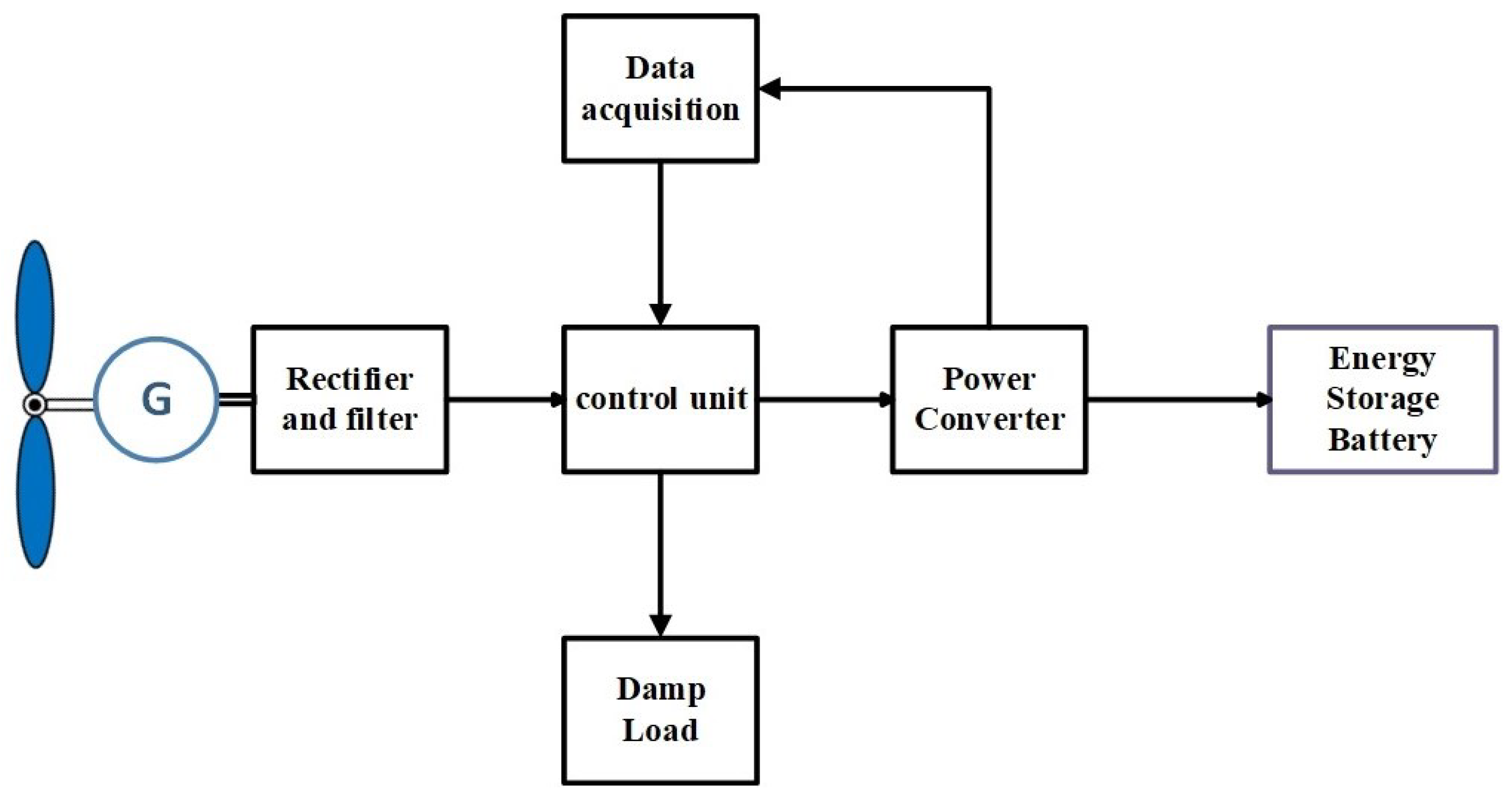
2. System Composition and Functional Requirements

A typical ocean buoy tidal energy power supply system mainly consists of a tidal energy generator, a power converter, a main controller, an energy storage battery, and a damp load, and its structure is shown in Figure 2.
The tidal current energy generator adopts a direct-drive outer rotor counter-rotating permanent magnet generator (PMG), the shape of which is shown in Figure 1. The dual outer rotor counter-rotating component captures the tidal current energy and outputs three-phase alternating current through the direct-drive permanent magnet generator. The design parameters of the tidal energy generator are shown in Table 1.
The current is able to obtain a stabilized output voltage from the generator output through the power converter, and the main controller realizes the voltage stabilization and power adaptive regulation under a wide flow rate range by controlling the power converter and the unloading load. The research objective of this paper is to determine the stabilized output voltage under wide dynamic voltage input and power adaptive regulation under the wide flow rate condition of the power converter.

3. Design and Analysis of Power Conversion Structures

3.1. Power Conversion Topologies

In this paper, a cascaded DC transformer structure for a Boost + LLC resonant converter is proposed, which consists of an input stage, an isolation stage, and an output stage. The cascaded DC/DC converter topology is shown in Figure 3.
The full−bridge LLC consists of a switching network, LLC resonant network, and isolated rectifier circuit  T 1 T 4 . In the switching network of the full-bridge LLC circuit are four power switching tubes of the converter, the resonance capacitance  C r , the series resonant inductance  L r , and the excitation inductance  L m , forming the resonant network, and the secondary side consists of the full-bridge rectifier circuit and the capacitive filtering circuit. The resonant network has two resonant frequencies, one for  L r  and  C r  and one for  L r + L m  and  C r  within which the converter operates [23].
f r = 1 2 π L r C r
f m = 1 2 π L r + L m C r
When the switching frequency is  f s < f m , the converter operates in the capacitive region, in which case the excitation current will be reversed before the switching tube is disconnected and the switching tube will not be able to realize the ZVS conduction; when the switching frequency is  f s > f m , the converter operates in the inductive region, and the switching tube on the primary side is able to accomplish the ZVS conduction; if the switching frequency of the converter is further limited to  f m < f s < f r , then the rectifier diode on the secondary side can turn off ZCS. The input voltage Vin is firstly boosted by the Boost circuit, which can realize the boost regulation of a wide input range by combining with its own boost characteristic. The low-voltage regulated output of the converter is achieved through the regulation of the rear full-bridge LLC circuit, and through the high-frequency transformer, the energy is transferred to the load through the resonant cavity and the isolation of the modular voltage input and output can be attained [17].
The resonant transformation circuit is analyzed by the fundamental wave analysis method; R e q is the equivalent resistance coupled to the primary measurement. Let the transformation ratio be 1:n, and the equivalent load is shown in Equation (3).
R e q = 8 R 0 n 2 π 2
The dc voltage gain of the LLC converter is obtained based on the fundamental equivalent circuit analysis [24].
M = 1 f n 1 f n 2 Q 2 + 1 + 1 λ 1 λ f n 2 2
where the normalized frequency  f n  is the ratio of frequency  f s  to  f r , λ  is the ratio of excitation inductance  L m  to the series resonant inductance  L s , and Q is the quality factor.
Practical implementation faces magnetic design constraints:
(a)
Core loss follows Steinmetz’s equation, requiring low-loss ferrites (e.g., 3C95) for >100 kHz operation;
(b)
Thermal derating necessitates <80% flux density at 100 °C ambient temperature;
(c)
Marine conditions reduce heat dissipation by 15% due to conformal coating. These constraints limit maximum power density to 0.8 W/cm³ in our buoy implementation.

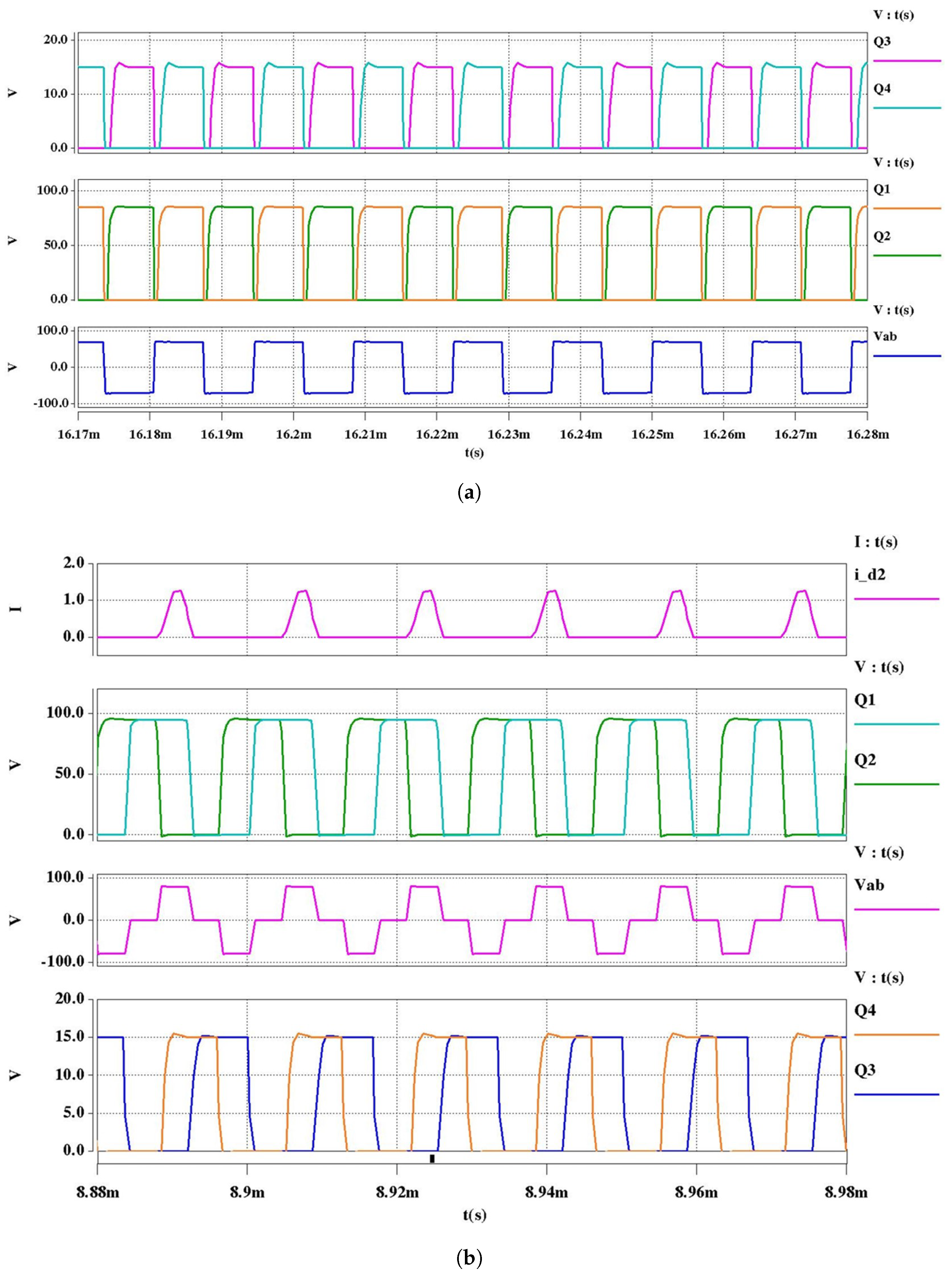
3.2. Operating Modal Analysis

The system operates over a wide input voltage range, and as the input voltage increases, the voltage stress on the switching devices and capacitors will also increase, which increases the difficulty of device selection. At the same time, the frequency variation range of the LLC resonant converter will be greatly increased, which increases the difficulty of the parameter design of the magnetic components. In order to effectively reduce the voltage and narrow the switching frequency range, two control strategies, PFM and PWM, are used to enhance the regulation range of the LLC. In general, the amplitude change of the input voltage contains three operating modes: when the voltage is less than 60 V, the Boost circuit assumes the boost and MPPT function; when the voltage is higher than 60 V and lower than 80 V, no maximum power tracking control is used through the LLC circuit for buck regulator control; and when the voltage is higher than 80 V at the same time as turning on the LLC circuit for buck control, access to the unloading voltage divider load for voltage reduction is provided.
When the converter is controlled by frequency conversion, this paper states that the converter works in frequency conversion mode (PFM), and its main working waveform is shown in Figure 4. In the figure,  Q 3  and  Q 4  are the corresponding bridge arm drive signals on the low−voltage side, Vab is the voltage at the two points AB in Figure 3, and  Q 1 Q 4 Q 2 , and  Q 3  conduct alternately to control the gain by changing the frequency. From the  Q 4  pole and pole voltage shown in Figure 4, it can be seen at this time that  Q 4  is in the zero−voltage−conduction state. The converter works in the phase shift (PWM) mode, and the switching network of the switching devices in the operating frequency fs remains unchanged by adjusting the phase shift angle of the converter to control the waveform so as to achieve the control of the converter’s operating state. This paper uses IR2104 as a driver in the Saber circuit for the modal simulation of the LLC circuit. Table 2 and Figure 4 show the specific modes of the phase shift control mode.
Thereafter, another half cycle is started with the same modes of operation as in the previous half cycle.

4. Analysis of Control Strategies

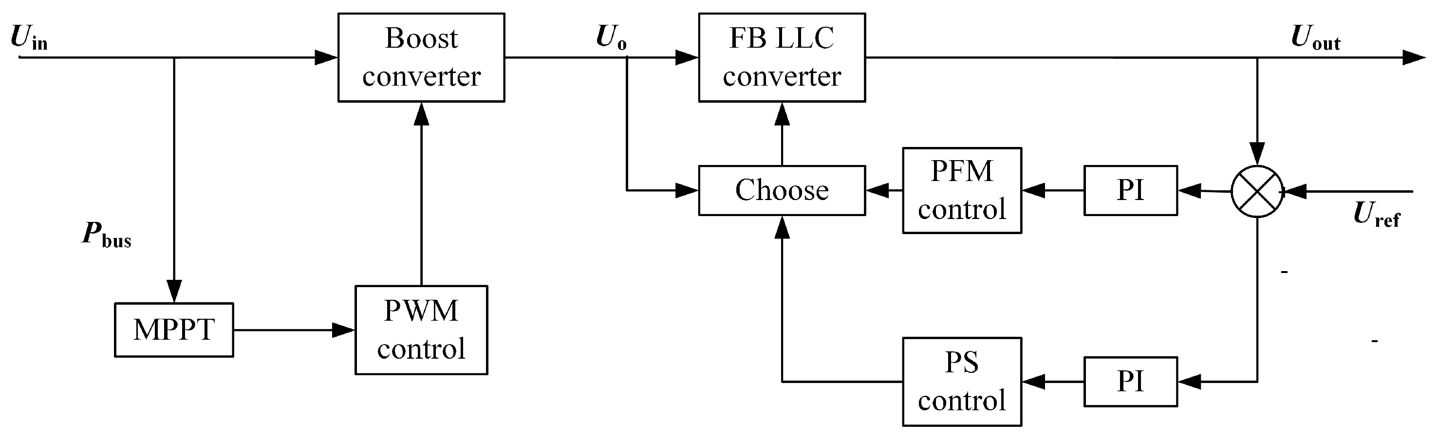
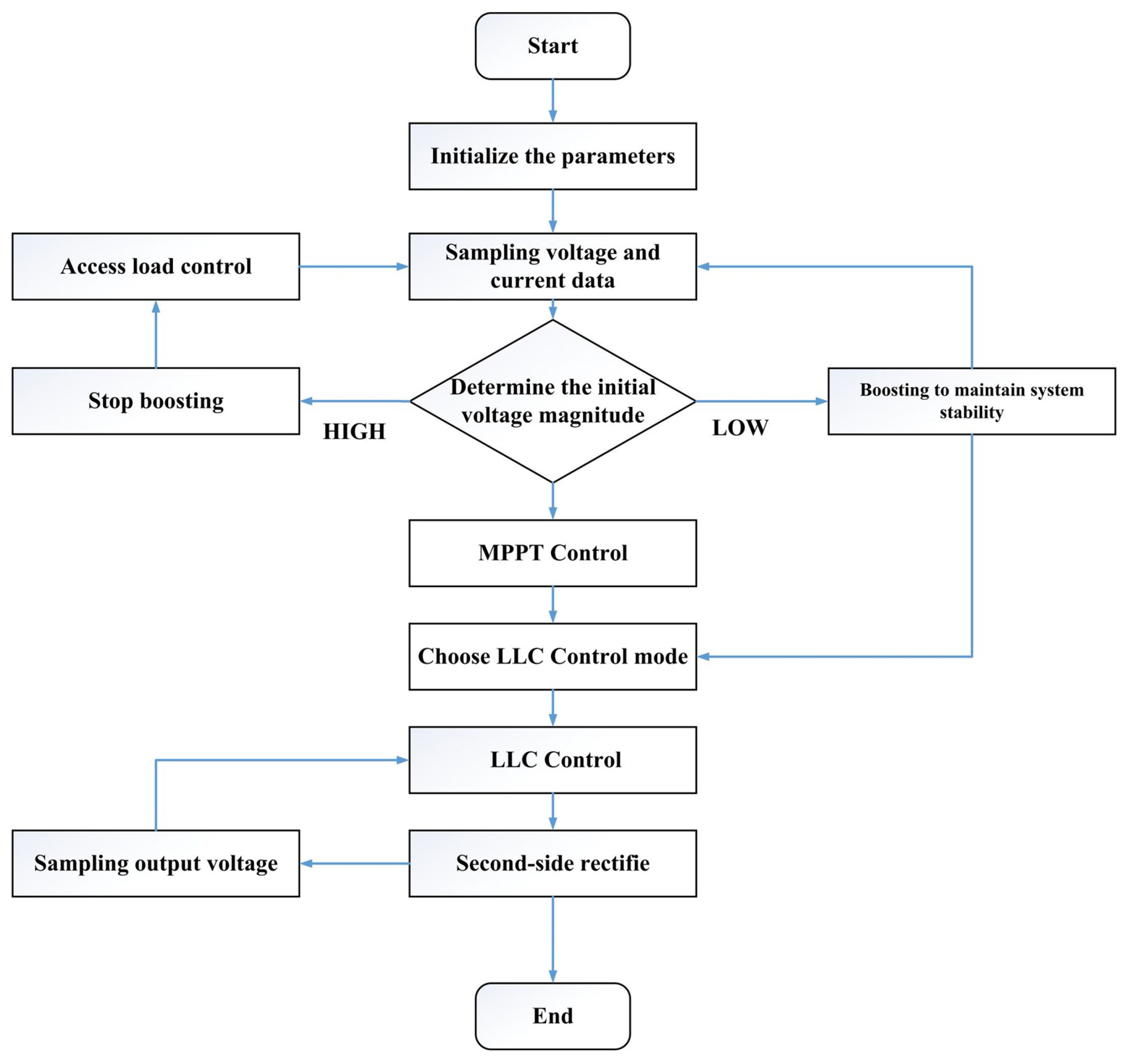
4.1. Control System Structure

The control system consists of two algorithms, namely a Boost circuit to realize the MPPT function and a full-bridge LLC circuit to ensure the stability of the output side; according to the input voltage with timely access to the protection circuit, to prevent system damage from overvoltage, the circuit system of a number of locations for the voltage and current sampling is used as an input parameter to select the appropriate form of control.
In order to realize wide voltage regulation, a variable−mode inverter hybrid control strategy is used in this paper. The control uses a simple single voltage closed-loop PFM/PWM control strategy, which can simplify the design of the control circuit and is easy to obtain [25,26]. A digital control method is used to control the drive signals of the inverter, and the control block diagram of the Boost + LLC inverter is shown in Figure 5, in which  V bus  is the bus voltage,  V ref  is the reference voltage on the output side, and  V error  is the error voltage. The system state is sampled by the sensor and communicated to the control unit, and the feedback signal of the Boost circuit comes from the motor output power as well as the bus voltage; the LLC feedback signal comes from the system output voltage. When the generator output power changes, the MPPT algorithm will control the Boost circuit to perform the maximum power tracking operation, and the LLC is responsible for selecting the operating mode to adjust the switching tube drive signal according to the input voltage so that the voltage is stabilized and remains efficient over the entire input voltage range.

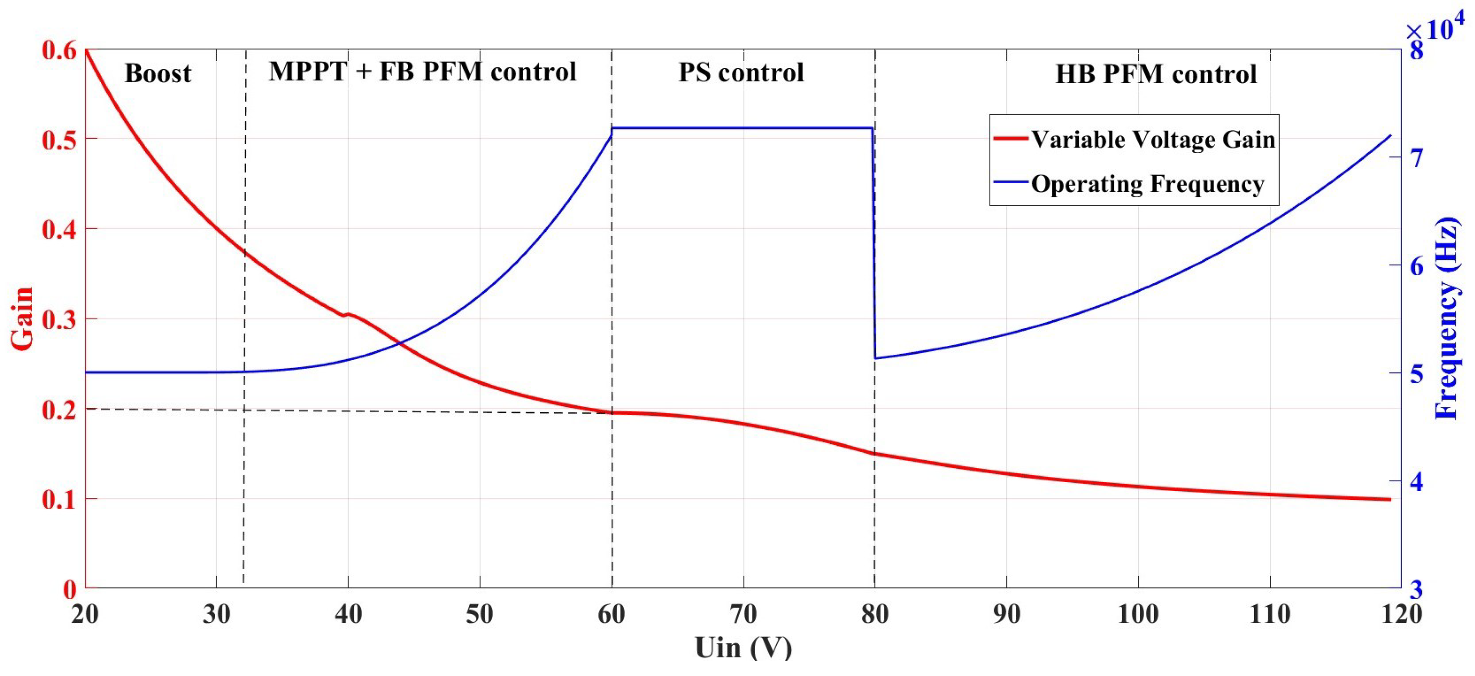
4.2. Variable Mode Frequency Control

Using the double half-bridge driver to realize the above control of the full-bridge circuit, the control is divided into the three following stages: using the sampling of the input voltage of the LLC circuit to determine the operating state, when the input voltage is low and using the full-bridge frequency control mode, the duty cycle of  50 %  frequency control, the output voltage sampling value, and the error comparison between the output voltage value as a given frequency PI controller input are determined. When the input voltage rises to a certain set value, the phase shift control mode is used to generate a phase shift angle through the input of the phase shift PI controller, at which time the switching frequency of the switching tube is constant, i.e., it is the resonant frequency, so that the change in the switching frequency can be minimized and a smooth transition can be achieved. The normalized gain of the phase-shifted LLC can be expressed as follows:
M 2 = 1 + cos θ 2 f n 1 f n 2 Q 2 + 1 + 1 λ 1 λ f n 2 2
When the input voltage is further increased to a certain value, the half-bridge frequency control mode is used to stop the PI control of the phase shift control, with  Q 1  and  Q 2  for frequency control, and the other half-bridge driver generates the constant on and constant off signals to realize the half-bridge LLC control. In order to prevent equipment damage caused by excessive voltage, the output voltage of the starting frequency of this mode is lower than the reference voltage and, therefore, further frequency control is required. The normalized gain of the half-bridge LLC can be expressed as
M 3 = 1 2 f n 1 f n 2 Q 2 + 1 + 1 λ 1 λ f n 2 2
According to Equations (5) and (6), the voltage gain of the full-bridge LLC resonant converter is two times that of the half-bridge in the case of consistent circuit parameters. Accordingly, the primary side switch tubes  S 2  and  S 4  using the control of the phase shift drive signal convert the resonant converter from the full-bridge mode transition to the phase-shift mode when the voltage output is higher, and the resonant converter naturally achieves two times the gain adjustment when combined with Formulas (4)–(6). The variable-mode control of the modulation gain is shown in Figure 6.

4.3. Power Tracking Control

4.3.1. Standard Gray Wolf Optimization Algorithm

The GWO algorithm simulates the leadership hierarchy and hunting mechanism of gray wolves in nature [27]. The potential optimal solution of the problem is regarded as the optimal prey location, and the gray wolf location is regarded as a feasible solution of the problem. The artificial wolf pack has a hierarchical organizational structure, consisting of elite wolves  α , β ,  and  δ  and ordinary wolves; by modeling the social hierarchy of the wolf pack in GWO, each low-priority artificial wolf needs to follow the instructions issued by high-priority artificial wolves in hunting activities. Under the command of elite wolves that can better grasp the optimal prey information, the artificial wolves carry out hunting activities. In order to update the position of wolves, the following mathematical model is proposed:
D = C X p ( t ) X p ( t ) X ( t + 1 ) = X p ( t ) A D
Here, t denotes the number of iterations, D, A, and C are denoted as valid vectors,  X p  represents the prey position, and X denotes the current position vector of the gray wolf [28]. The vectors A and C are computed as follows:
A = 2 a r 1 a
C = 2 r 2
where a is reduced from 2 to 0 during the iteration process and  r 1  and  r 2  are random vectors in  [ 0 , 1 ] . The search process is mainly performed under the guidance of  α ,   β , and  γ  gray wolves, and the position update method is as follows:
D α = C 1 · X α ( t ) X ( t ) D β = C 2 · X β ( t ) X ( t ) D δ = C 3 · X δ ( t ) X ( t )
X 1 = X α ( t ) A 1 · D α X 2 = X β ( t ) A 2 · D β X 3 = X δ ( t ) A 3 · D δ
X ( t + 1 ) = x 1 + X 2 + X 3 3

4.3.2. Improved Gray Wolf Optimization Algorithm (PSO-GWO)

In the process of position updating, the GWO algorithm only considers the position information of a single gray wolf and the position information of the optimal, suboptimal, and sub-suboptimal solutions of the wolf pack, which realizes the exchange of information between the individuals and the wolf pack but ignores the exchange of information between the gray wolves and their own experience, which makes the gray wolves prone to stagnate in early searching for the optimal solution when they are hunting. Therefore, the idea of the particle swarm algorithm (PSO) is introduced to improve the position update process. Thus, a hybrid PSO-GWO algorithm is formed to make the wolf pack’s optimization process memorable. In addition, an inertia constant w is introduced to enhance the PSO-GWO hybrid algorithm to balance the global search capability and local exploitation capability. Therefore, during the optimization process, the speed and position of the particles with higher adaptability are made to be updated to increase the optimization ability of the head wolf. In this paper, based on the GWO algorithm, it is easy to fall into local optimization and the search range is small. Thus, it is necessary to carry out the following improvements:
(1)
Improved Chebyshev chaotic mapping
The basic GWO algorithm uses random generation to generate the initial population, which cannot ensure that the initialized individuals are distributed as evenly as possible throughout the search area, which is not conducive to improving the global search performance of the algorithm. For this reason, this paper utilizes the randomness and traversal of chaotic sequences and selects the improved Chebyshev mapping equation to generate the initial populations so that the initial populations can be uniformly distributed in the search range, which increases the diversity of the search and avoids the local optimization phenomenon as much as possible (Figure 7). The improved Chebyshev’s mapping equation is
x ( i + 1 ) = ( cos ( i a cos ( x ( i ) ) ) + 1 ) 0.5
(2)
Nonlinear convergence factor adjustment strategy
In the basic GWO algorithm, the value of the convergence factor a decreases linearly with the increase in the number of iterations. In order to increase the global search capability in the early stage, this paper converts the convergence factor from a linear distribution to a nonlinear distribution in the early stage to increase the search range and increase the global search capability; the search for excellence in the late stage of the change in the steepness of the change is more adapted to the local search for excellence. The improvement of the nonlinear distance convergence factor a is as follows:
a = 2 2 ( ( exp ( iteration / 50 ) 1 ) / ( exp ( 1 ) 1 )
(3)
Adaptive limiting factor
In the basic GWO algorithm, there are particle boundaries to prevent the output particles from exceeding the limited range, and in the case of the input parameter, i.e., voltage and current, which is constantly changing, a single particle-limiting value will potentially subject the subsequent circuits to excessive voltages; thus, it is necessary to constrain the iterative particles in real time, and the adaptive limiting equations are as follows:
D V i n max V i n D 0.8
The maximum value of the voltage in the equation is taken as 100 V to prevent the output voltage of the Boost circuit from being too high.
(4)
PSO-GWO hybrid strategy
The PSO algorithm is a group intelligence-based optimization algorithm inspired by the foraging behavior of birds [29]. During the search process, each particle adjusts its position based on its own experience and the experience of its neighboring particles by using the optimal positions encountered by itself and its neighboring particles. The particle swarm direction is defined by a set of particles around the particle and its historical experience. The main advantage of the PSO algorithm is that it is easy to implement and has few adjustable parameters. Equation (16) shows the position update of the PSO [30]:
v i k + 1 = v i k + c 1 r 1 P best k x i k + c 2 r 2 g best x i k x i k + 1 = x i k + v i k + 1
In order to balance the search speed and global search ability, the predation process of ordinary wolves remains unchanged, while for the head wolf, the PSO algorithm is adopted to update the position and speed to increase his global search ability and improve the probability of jumping out of the local optimal solution; the algorithm flow is shown in Figure 8.
Steps of GWO algorithm
  • Initialize the gray wolf population parameters, among which are the gray wolf population size N, the maximum number of algorithmic optimization searches tmax, the spatial dimension dim, and the range of the algorithmic optimization space  [ lb , ub ] ;
  • Collect voltage and current parameters and input them into the algorithm.
  • Determine the population range based on the input parameters.
  • Carry out hybridization strategy of the gray wolf population to increase the genetic diversity of the population and update the geographic location of the gray wolf population.
  • Calculate the fitness of each individual wolf in the current gray wolf population and determine the  α  wolf,  β  wolf, and  δ  wolf.
  • Determine the parameter value of C according to the equation while confirming parameter A.
  • Update the position of each individual wolf in the gray wolf population and confirm the prey position according to Equations (5) to (8); additionally, perform particle position range restriction.
  • Update the position of individual gray wolves according to Equation (13) and recalculate the fitness value of each gray wolf.
  • Determine the optimal gray wolf individual in the current generation population and execute.

5. Simulation Modeling Analysis

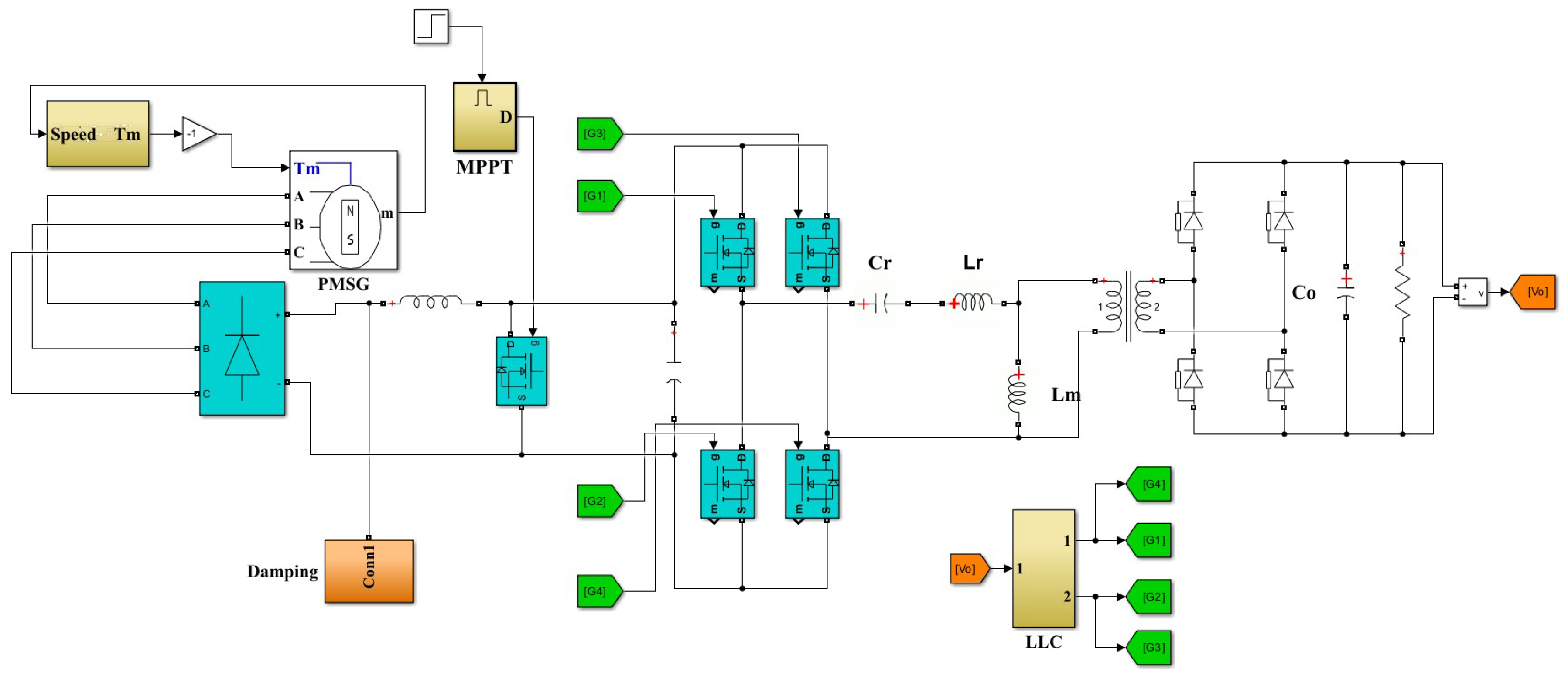
5.1. System Simulation Model

In order to verify the operation characteristics of the proposed tidal current energy converter, Saber and Matlab simulation models were constructed for verification.
In the Saber environment, an LLC full−bridge circuit with IR2104 as the driver chip was constructed, and the simulation was carried out under the conditions of different operating modes at different frequencies. The correctness of the DC gain curve was verified by analyzing and comparing the interrelationships between the input voltage of the power switching tubes,  U in , and the output voltage,  U o , in the simulation results. The simulated waveforms are shown in Figure 9.
In order to verify the effectiveness of the variable−mode, variable−frequency hybrid control, simulation was performed to check the reasonableness of the algorithm and topology by inputting the change in the seawater flow rate. The parameters of the experimental algorithm in this study were set as follows: the number of gray wolves in the artificial wolf pack was  N W = 10  and the maximum number of cycles was  N m c = 50 . The solver was set to Bogacki–Shampine, and the sampling step was not fixed. The overall structure of the simulation is shown in Figure 10.

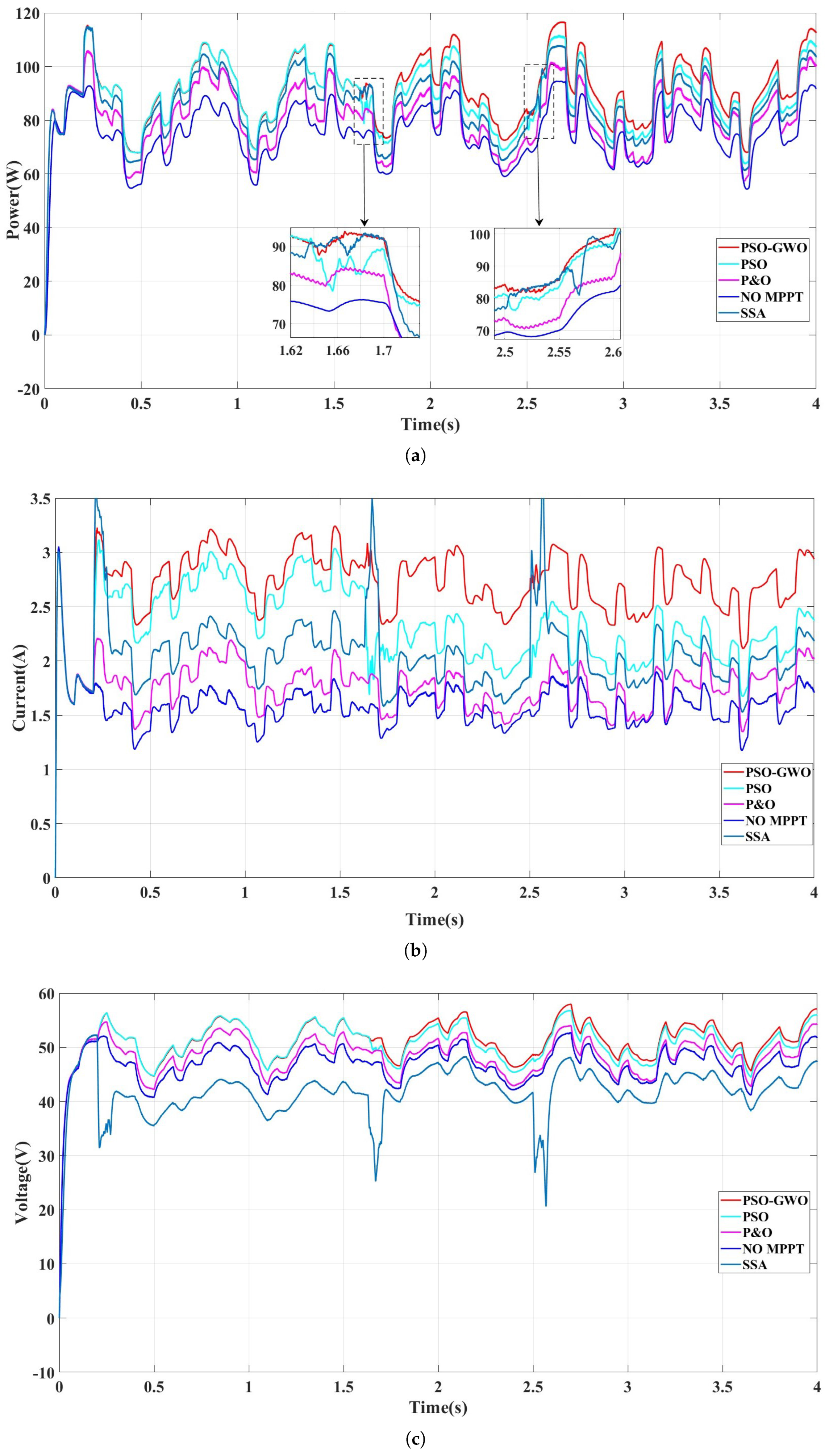
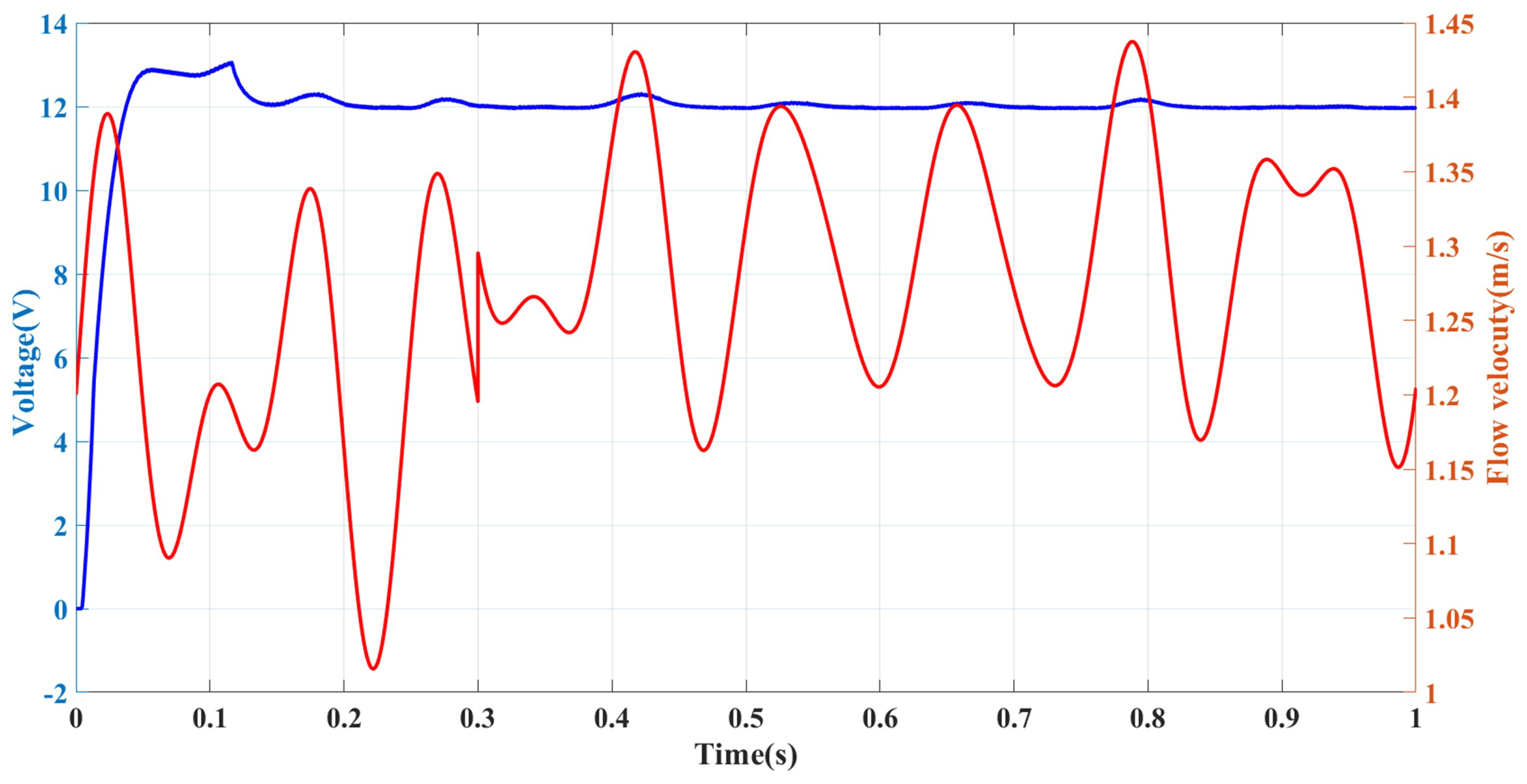
5.2. Results and Discussion

The Simulink simulation model of a tidal energy generation system based on PSO−GWO, GWO, and PSO algorithms was run under a flow velocity of  1 m / s 0.8 m / s ,  and  0.6 m / s , and the evaluation of the results was carried out, as shown in Figure 11.
Under constant flow velocity, the generator reaches a steady state after starting at 0.2 s. Accessing the maximum power tracking control simulation, the MPPT control is carried out using the P&O, PSO, GWO, and PSOGWO control algorithms, respectively, under the same conditions. The magnitude of the power increase decreases with the increase in the flow velocity, i.e., the effect of the MPPT control is more obvious at low flow velocities, in which the  0.6 m / s  flow velocity in the GWO simulation causes the motor to stall due to the no-particle boundary restriction, and the simulation stops after 0.25 s. The remaining three simulation methods effectively increase the output power of the generator, and the PSOGWO algorithm has the highest simulation enhancement. The output power is increased by 9 W compared with that of the no-control state, and it starts to converge rapidly in about 20 iterations and searches within a small range: the  P & O  algorithm is used in the searching process in the entire simulation process, so the output power is not stable; the PSO algorithm reaches convergence in 0.3 s, and there is also an oscillation phenomenon in the late stage of the optimization search; the maximum efficiency can be improved by  8 %  at a flow rate of  0.8 m / s , while at a flow rate of  1 m / s , the efficiency can be improved by  4 %  and the power output under the control of the four algorithms is not much different, with a difference of only 1–2  W . In terms of the convergence speed, compared to the other algorithms, the PSO-GWO convergence speed is faster and more stable than other algorithms.
The flow rate is in the environment of 0.7–0.9 m/s and is changing constantly; the MPPT control is carried out from  0.1 m / s , and its voltage and current changes are shown in Figure 12, which shows that most of the time, the MPPT control effectively improves the output power of the motor and the overall power output is consistent with the trend of the flow rate magnitude. This demonstrates that the power capture effect of the PSO-GWO algorithm is better than other control algorithms and the output power decreases around 0.35 s due to the position of the particles in the optimization process before jumping out of the current range in the subsequent process. Thus, the output power is also improved. The use of PSO-GWO has a high average power output.
As shown above, the system reaches a steady state after startup and is controlled by MPPT to increase the captured power; the improved GWO algorithm can increase the output power by a small amount in the rated power state, which is more stable compared to other algorithms; and the improved algorithm can increase the output power more efficiently in the low-flow rate state operation, which is more responsive compared to traditional control algorithms.
As shown in Figure 13, the back-end LLC circuit is stabilizing the output voltage by varying the input voltage control method and selecting the control method according to different input voltages.

6. Conclusions

This paper analyzes in detail the working principle and operating characteristics of the full−bridge LLC resonant converter based on which a hybrid control strategy is proposed and a specific implementation scheme is given, which retains the standard GWO algorithm’s artificial wolf pack hierarchical structure and the elite wolf dominant prey mode; additionally, it adds a brand−new elite wolf searching strategy which enhances the local and global searching ability of the PSO−GWO algorithm; optimizes the encirclement formation strategy, wolf pack prey search mode, and redundant wolf pack structure; increases the dominance weight coefficient; optimizes the wolf pack search strategy; balances the local search and global search ability in the optimization process; and ensures that the PSO−GWO algorithm can effectively detach from the local optimum in the face of nonlinearity.
The converter has the following advantages: (i) it works better in inverter and phase-shift modes and operates efficiently over a wide input voltage range; (ii) the switching tubes achieve ZVS over the full voltage and load range; (iii) the secondary rectifier tubes achieve ZCS, and their voltage stresses are the output voltages; (iv) the range of the switching frequency variation is small, which makes it easy to optimize the design of magnetic components; and (v) it achieves maximum power tracking and control in an environment of varying flow rates to increase the system’s efficiency.

Author Contributions

Methodology, C.S.; software, C.S.; validation, F.Y.; resources, F.S.; data curation, C.S.; writing—original draft preparation, C.S.; writing—review and editing, F.S. and F.Y.; supervision, F.S. All authors have read and agreed to the published version of the manuscript.

Funding

This research was supported by the Natural Science Foundation of Jiangsu Province University (grant no. 20KJB470017).

Data Availability Statement

The original contributions presented in this study are included in the article. Further inquiries can be directed to the corresponding author.

Conflicts of Interest

The authors declare no conflict of interest. The funders had no role in the design of the study; in the collection, analyses, or interpretation of data; in the writing of the manuscript, or in the decision to publish the results.

References

  1. Wang, H.; Wu, W.; Cui, L.; Wu, Y.; Zhu, L.; Koutroulis, E.; Blaabjerg, F. A new wave energy converter for marine data buoy. IEEE Trans. Ind. Electron. 2022, 70, 2076–2084. [Google Scholar] [CrossRef]
  2. Xi, F.; Pang, Y.; Liu, G.; Wang, S.; Li, W.; Zhang, C.; Wang, Z.L. Self-powered intelligent buoy system by water wave energy for sustainable and autonomous wireless sensing and data transmission. Nano Energy 2019, 61, 1–9. [Google Scholar] [CrossRef]
  3. Larcher, D.; Tarascon, J.M. Towards greener and more sustainable batteries for electrical energy storage. Nat. Chem. 2015, 7, 19–29. [Google Scholar] [CrossRef] [PubMed]
  4. Ghefiri, K.; Bouallègue, S.; Haggège, J.; Garrido, I.; Garrido, A.J. Modeling and MPPT control of a Tidal Stream Generator. In Proceedings of the 2017 4th International Conference on Control, Decision and Information Technologies (CoDIT), Barcelona, Spain, 5–7 April 2017; pp. 1003–1008. [Google Scholar]
  5. Segura, E.; Morales, R.; Somolinos, J.; López, A. Techno-economic challenges of tidal energy conversion systems: Current status and trends. Renew. Sustain. Energy Rev. 2017, 77, 536–550. [Google Scholar] [CrossRef]
  6. Bahaj, A.S. Generating electricity from the oceans. Renew. Sustain. Energy Rev. 2011, 15, 3399–3416. [Google Scholar] [CrossRef]
  7. Keysan, O.; McDonald, A.S.; Mueller, M. A direct drive permanent magnet generator design for a tidal current turbine (SeaGen). In Proceedings of the 2011 IEEE International Electric Machines & Drives Conference (IEMDC), Niagara Falls, ON, Canada, 15–18 May 2011; pp. 224–229. [Google Scholar]
  8. Ghefiri, K.; Garrido, I.; Garrido, A.J.; Bouallègue, S.; Haggège, J. Fuzzy gain scheduling of a rotational speed control for a tidal stream generator. In Proceedings of the 2018 International Symposium on Power Electronics, Electrical Drives, Automation and Motion (SPEEDAM), Amalfi, Italy, 20–22 June 2018; pp. 1271–1277. [Google Scholar]
  9. Melikoglu, M. Current status and future of ocean energy sources: A global review. Ocean Eng. 2018, 148, 563–573. [Google Scholar] [CrossRef]
  10. Djebarri, S.; Charpentier, J.F.; Scuiller, F.; Benbouzid, M. Design methodology of permanent magnet generators for fixed-pitch tidal turbines with overspeed power limitation strategy. J. Ocean Eng. Sci. 2020, 5, 73–83. [Google Scholar] [CrossRef]
  11. Uihlein, A.; Magagna, D. Wave and tidal current energy—A review of the current state of research beyond technology. Renew. Sustain. Energy Rev. 2016, 58, 1070–1081. [Google Scholar] [CrossRef]
  12. Zhang, H.B.; Fletcher, J.; Greeves, N.; Finney, S.; Williams, B. One-power-point operation for variable speed wind/tidal stream turbines with synchronous generators. IET Renew. Power Gener. 2011, 5, 99–108. [Google Scholar] [CrossRef]
  13. Shahi, A.; Bhattacharjee, C. A study & analysis of fuzzy based P&O MPPT scheme in PMSG based wind turbine. In Proceedings of the 2018 Technologies for Smart-City Energy Security and Power (ICSESP), Bhubaneswar, India, 28–30 March 2018; pp. 1–4. [Google Scholar]
  14. Sousounis, M.C.; Shek, J.K.; Mueller, M.A. Modelling, control and frequency domain analysis of a tidal current conversion system with onshore converters. IET Renew. Power Gener. 2016, 10, 158–165. [Google Scholar] [CrossRef]
  15. Abokhalil, A.G. Control System of DFIG for Wind Power Generation Systems; LAP LAMBERT Academic Publishing: Saarbrücken, Germany, 2015. [Google Scholar]
  16. Abo-Khalil, A.G.; Alghamdi, A.S. MPPT of permanent magnet synchronous generator in tidal energy systems using support vector regression. Sustainability 2021, 13, 2223. [Google Scholar] [CrossRef]
  17. De Simone, S.; Adragna, C.; Spini, C. Design guideline for magnetic integration in LLC resonant converters. In Proceedings of the 2008 International Symposium on Power Electronics, Electrical Drives, Automation and Motion, lschia, Italy, 11–13 June 2008; pp. 950–957. [Google Scholar]
  18. Wu, X.; Bai, Z.; Ma, H. An LLC converter operating in super-wide output voltage range with variable-mode control strategy. In Proceedings of the 2018 IEEE International Power Electronics and Application Conference and Exposition (PEAC), Shenzhen, China, 4–7 November 2018; pp. 1–6. [Google Scholar]
  19. Cao, Q.; Li, Z.; Wang, H. Wide voltage gain range LLC DC/DC topologies: State-of-the-art. In Proceedings of the 2018 International Power Electronics Conference (IPEC-Niigata 2018-ECCE Asia), Niigata, Japan, 20–24 May 2018; pp. 100–107. [Google Scholar]
  20. Liang, Z.; Guo, R.; Wang, G.; Huang, A. A new wide input range high efficiency photovoltaic inverter. In Proceedings of the 2010 IEEE Energy Conversion Congress and Exposition, Atlanta, GA, USA, 12–16 September 2010; pp. 2937–2943. [Google Scholar]
  21. Jovanović, M.M.; Irving, B.T. On-the-fly topology-morphing control—Efficiency optimization method for LLC resonant converters operating in wide input-and/or output-voltage range. IEEE Trans. Power Electron. 2015, 31, 2596–2608. [Google Scholar] [CrossRef]
  22. Wu, H.; Zhan, X.; Xing, Y. Interleaved LLC resonant converter with hybrid rectifier and variable-frequency plus phase-shift control for wide output voltage range applications. IEEE Trans. Power Electron. 2016, 32, 4246–4257. [Google Scholar] [CrossRef]
  23. Deng, J.; Li, S.; Hu, S.; Mi, C.C.; Ma, R. Design methodology of LLC resonant converters for electric vehicle battery chargers. IEEE Trans. Veh. Technol. 2013, 63, 1581–1592. [Google Scholar] [CrossRef]
  24. De Simone, S.; Adragna, C.; Spini, C.; Gattavari, G. Design-oriented steady-state analysis of LLC resonant converters based on FHA. In Proceedings of the International Symposium on Power Electronics, Electrical Drives, Automation and Motion SPEEDAM, Taormina, Italy, 23–26 May 2006; pp. 200–207. [Google Scholar]
  25. Yamamoto, J.; Zaitsu, T.; Abe, S.; Ninomiya, T. PFM and PWM hybrid controlled LLC converter. In Proceedings of the 2014 International Power Electronics Conference (IPEC-Hiroshima 2014-ECCE ASIA), Hiroshima, Japan, 18–21 May 2014; pp. 177–182. [Google Scholar]
  26. Yudi, X.; Xingkui, M.; Zhe, Z.; Shi, Y. New hybrid control for wide input full-bridge LLC resonant DC/DC converter. In Proceedings of the 2018 3rd International Conference on Intelligent Green Building and Smart Grid (IGBSG), Yilan, Taiwan, 22–25 April 2018; pp. 1–4. [Google Scholar]
  27. Mirjalili, S.; Mirjalili, S.M.; Lewis, A. Grey wolf optimizer. Adv. Eng. Softw. 2014, 69, 46–61. [Google Scholar] [CrossRef]
  28. Lettenmaier, T.; Von Jouanne, A.; Brekken, T. A new maximum power point tracking algorithm for ocean wave energy converters. Int. J. Mar. Energy 2017, 17, 40–55. [Google Scholar] [CrossRef]
  29. Eberhart, R.; Kennedy, J. A new optimizer using particle swarm theory. In Proceedings of the MHS’95 Sixth International Symposium on Micro Machine and Human Science, Nagoya, Japan, 4–6 October 1995; pp. 39–43. [Google Scholar]
  30. Abdelshafy, A.M.; Hassan, H.; Jurasz, J. Optimal design of a grid-connected desalination plant powered by renewable energy resources using a hybrid PSO–GWO approach. Energy Convers. Manag. 2018, 173, 331–347. [Google Scholar] [CrossRef]
Figure 1. Schematic diagram of ocean buoy observation platform based on tidal energy power supply.
Jmse 13 01129 g001
Figure 2. Structure of a typical ocean buoy tidal current energy power supply system.
Jmse 13 01129 g002
Figure 3. Cascaded DC/DC converter topology.
Jmse 13 01129 g003
Figure 4. Circuit simulation waveform. (a) PFM operating waveforms and Zero-voltage switching on under PFM; (b) PWM operating waveforms.
Jmse 13 01129 g004
Figure 5. Overall control method.
Jmse 13 01129 g005
Figure 6. Variable mode control of modulation gain.
Jmse 13 01129 g006
Figure 7. Improved mapping of Chebyshev.
Jmse 13 01129 g007
Figure 8. PSO-GWO algorithm flow.
Jmse 13 01129 g008
Figure 9. Saber circuit model.
Jmse 13 01129 g009
Figure 10. Matlab circuit model.
Jmse 13 01129 g010
Figure 11. Simulation results based on constant flow rate. (a) Based on a flow velocity of 0.6 m/s; (b) Based on a flow velocity of 0.8 m/s; (c) Simulation results based on 1 m/constant flow rate.
Jmse 13 01129 g011
Figure 12. Power control at variable flow rates. (a) Variation of power at variable flow rates; (b) Variation of current at variable flow rates; (c) Voltage variation at variable flow rates.
Jmse 13 01129 g012
Figure 13. Regulated output of different control methods.
Jmse 13 01129 g013
Table 1. Design parameters of trend energy generator.
Name ParameterValue
Rated power120 W
Rated voltage36 V
Impeller diameter Φ 1.8 m
Rated flow rate1.0 m/s
Rated speed28 rpm
Table 2. PWM operating modes.
Modal Q 1 Q 2 Q 3 Q 4 V ab i d
1ConductedConductedShutdownShutdown00
2ConductedShutdownShutdownShutdown0
3ConductedShutdownShutdownConducted+
4ShutdownShutdownShutdownConducted
5ShutdownShutdownConductedConducted00
Disclaimer/Publisher’s Note: The statements, opinions and data contained in all publications are solely those of the individual author(s) and contributor(s) and not of MDPI and/or the editor(s). MDPI and/or the editor(s) disclaim responsibility for any injury to people or property resulting from any ideas, methods, instructions or products referred to in the content.

