Article

An Examination of the Failure Envelope of Finned Suction Anchors Subjected to Combined Vertical–Horizontal Loadings in Clay Through Numerical Modeling

Department of Civil and Environmental Engineering, Kongju National University, 1223-24 Cheonan-Daero, Seobuk, Cheonan 31080, Republic of Korea
*
Author to whom correspondence should be addressed.
J. Mar. Sci. Eng. 2025, 13(6), 1104; https://doi.org/10.3390/jmse13061104
Submission received: 16 April 2025 / Revised: 19 May 2025 / Accepted: 24 May 2025 / Published: 30 May 2025
(This article belongs to the Special Issue Marine Geotechnical Applications in Marine Structures)

Abstract

The addition of fins to suction anchors has been proposed to enhance bearing capacity in combined loadings. This study examines the failure envelope of finned suction anchors subjected to combined vertical–horizontal loadings in normally and lightly over-consolidated clay using the finite element method, focusing on fin capacity enhancement and fin efficiency against penetration resistance. Parameters considered include different length-to-diameter ratios of the suction anchor, as well as different fin-to-shaft-length ratios, to evaluate the effect on capacity. The addition of fins expands the vertical–horizontal failure envelope, minimally altering the shape of the failure envelope. The fin factor (the ratio of the finned suction anchor capacity to the conventional suction anchor capacity) increases with fin lengths but exhibits minimal dependence on length-to-diameter ratios. A nonlinear relationship between fin length and fin factor (both vertical and horizontal) with a distinct trend is observed in horizontal capacity. Fin efficiency (the ratio of capacity to penetration resistance) decreases with increasing fin length except at a fin length-to-shaft ratio of unity in horizontal capacity.

1. Introduction

Suction anchors are frequently employed as anchor solutions for mooring floating production, storage, and offloading (FPSO) vessels [1] and offshore wind turbines in deep-water conditions. Their popularity arises from advantages, including ease of installation, reusability, and high load-carrying capacity, especially under combined vertical and horizontal (VH) loading, as well as under moment loading [2]. A further benefit of suction anchors is that they may be positioned with precision. For floating offshore wind substructures, suction anchors can be utilized either as a single point anchor for a single mooring line [3] or as shared anchors for multiple mooring lines [4], resulting in economic benefits. In addition, grouped suction anchor systems—consisting of two or more suction anchors rigidly connected—have been proposed to enhance overall pullout resistance [5]. The typical design of a single point anchor includes a pad eye positioned at approximately two-thirds of the skirt depth to optimize load transfer, minimize local stress concentrations, and enhance soil–anchor interaction [6].
The installation procedure for suction anchors involves self-weight penetration followed by suction-assisted penetration [7,8,9,10,11,12,13,14]. Initially, the suction anchor penetrates the seabed by gravity. After initial embedment, controlled suction pressure creates a pressure differential between the internal cavity and the surrounding soil, driving the suction anchor to its target depth. In deep-water conditions where soft clay or very-low-strength soils are present near the mudline, larger diameters and longer shaft lengths are often necessary to develop sufficient vertical and lateral resistance. The use of longer shafts (also known as “skirts”) delivers a more stable and reliable foundation [15].
Methods of enhancing axial and pullout resistance in pile foundation systems include the addition of belled piles, geogrid reinforcement [16], and the use of under-reamed piles [17,18]. In addition, modifications such as the addition of fins (also referred to as “wings”) have been explored to enhance load-bearing capacity and address the limitations of conventional cylindrical suction anchors. Fins are attached to the shaft to improve lateral resistance and rotational stiffness, thereby reducing displacement and tilting under extreme environmental loads. The effectiveness of fins was first studied in monopile foundations for offshore wind turbines, where fins were found to increase lateral stiffness and reduce bending moments at the pile head [19]. Experimental and numerical studies on finned monopiles in cohesionless soils (e.g., sand) have demonstrated that fins significantly enhance lateral capacity by mobilizing passive soil resistance [20,21,22,23,24]. Research indicates that finned monopiles can achieve 10% to 60% greater lateral (horizontal) capacity than conventional monopiles, with triangular and rectangular fin shapes being the most effective [21]. Furthermore, the maximum efficiency is observed when the fin length is approximately half the pile length [24]. Regardless of the specific shape or position of the fins, finned piles consistently exhibit a stiffer system response compared with monopiles without fins, emphasizing the overall structural benefits [21,25,26]. Increased stiffness achieved via the addition of stiffeners [27] or fins also improves fatigue performance, which is beneficial in long-term cyclic loading induced by waves and winds.
For suction anchors in clay, similar advantages have been observed [1,4,28,29]. Studies have indicated that fins enhance pullout resistance for both top- and side-loaded suction anchors [1,30]. Additionally, finned suction anchors appear to be the most optimal solution in terms of anchor efficiency (defined as capacity/weight ratio) when compared with conventional suction and torpedo anchors [29]. However, the effectiveness of fins depends on their positioning. For top-loaded suction anchors, fins are most effective when placed near the upper part of the shaft, whereas for side-loaded anchors, the optimal fin placement is near the attachment point [1]. Additionally, under top-loaded conditions, the failure envelopes of different fin positions along the skirt intersect, while no intersection occurs under side-loaded conditions. A larger volume of soil is mobilized when fins are included and extended [1]. However, further investigation is required to fully understand the effects of fin geometry (i.e., fin length) and fin location on the different length-to-diameter ( L s / D p ) ratios and failure envelopes in clay.
This study aims to examine the failure envelope of finned suction anchors subjected to combined vertical and horizontal (VH) loading in clay through numerical modeling. Specifically, it investigates the effects of fin length (in terms of L f / L s ) and the L s / D p ratio on capacity enhancement and failure mechanisms. Additionally, this study evaluates the efficiency of fins with regard to installation performance, providing insights into the optimal design for improving suction anchor performance in offshore applications.

2. Methodology

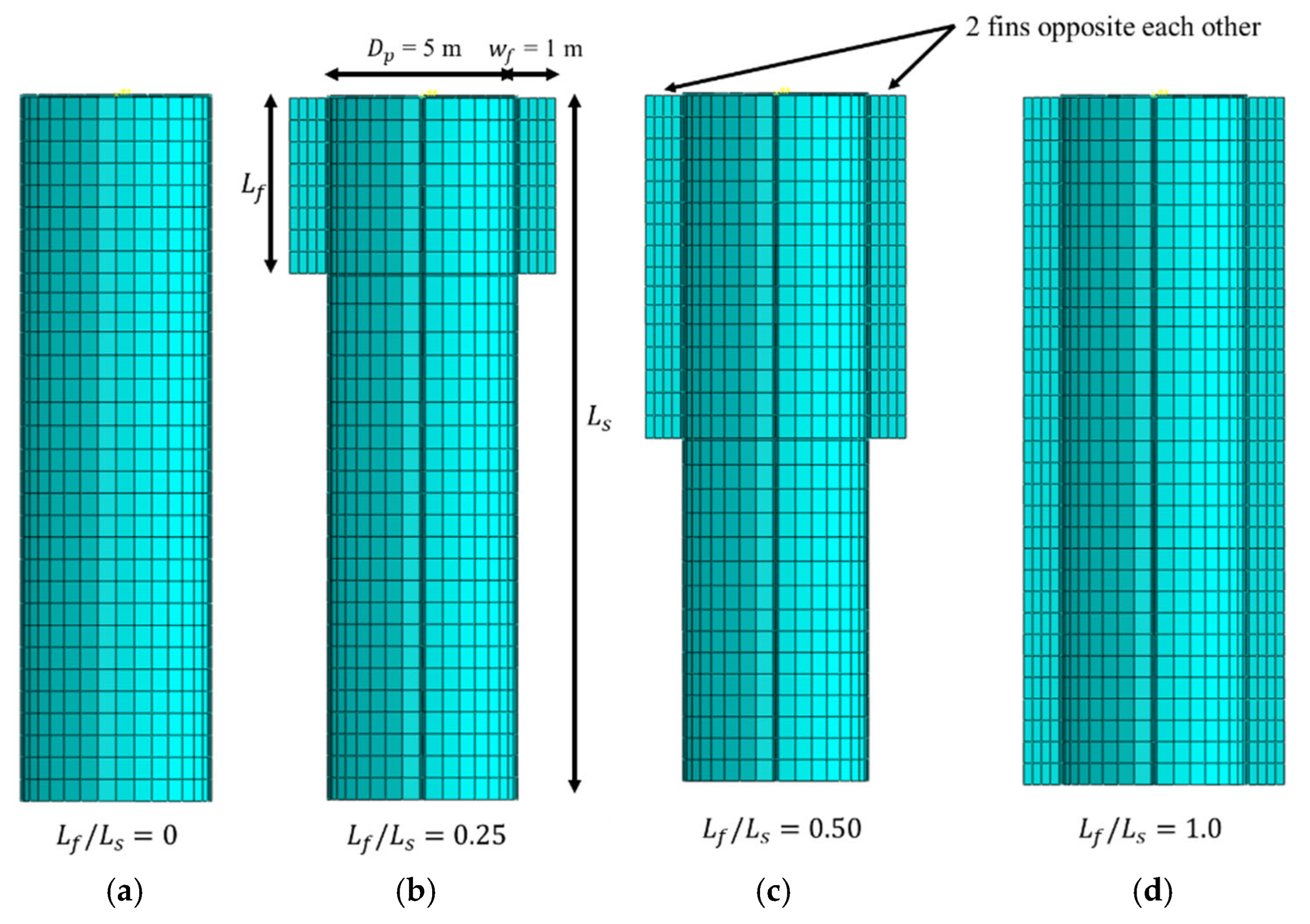
2.1. Geometry and Parameters

Figure 1 ( L s / D p = 3 cases as a representative) shows the geometry of the ratio of finned suction anchors of different fin lengths, L f , to shaft length, L s : L f / L s = 0, 0.25, 0.50, and 1.0. The length-to-diameter ratio, L s / D p , of the suction anchors varies from 1.5 to 3 and 5. The diameter, D p , is maintained at 5 m for all analyses since D p does not affect the normalized bearing capacities [31]. Four fins are considered and the width of the fins is constant at 0.2 D p (1 m) in all analyses. The fin width is adopted by Garcia and Panayides [1]. The top lid, skirt, and fin thickness, t, is fixed at 50 mm. The finned suction anchors are modeled as a rigid body.
Two soil profiles, normally consolidated (NC) and lightly over-consolidated (LOC) under undrained conditions, are considered in this study, as shown in Figure 2. The parameters are adopted based on the soil profiles used by Supachawarote [6]. In a normally consolidated soil profile, the undrained shear strength, S u , linearly increases at the rate k of 1.5 kPa/m and S u 0 = 0 kPa, with an effective unit weight, γ , of 6.0 k N / m 3 . For a lightly over-consolidated soil profile, the undrained shear strength, S u , is constant S u 0 = 5 kPa to a depth, z = 5 m below the seabed and linearly increased with z > 5 m at the rate, k of 2 kPa/m. The effective unit weight in lightly over-consolidated soil is 7.2 k N / m 3 . The earth pressure coefficient, K 0 is 1 for constant S u , and 0.55 and 0.65 for NC and LOC, respectively, when S u varies linearly with depth.
The soil is modeled as an elastic, perfectly plastic material, obeying the Mohr–Coulomb criterion [32,33,34]. The elastic behavior of clay is defined by Poisson’s ratio, ν , of 0.49 to simulate the constant volume response of the clay under undrained conditions [35,36], and Young’s modulus E was set to 500 S u throughout the soil profile. The soil parameters used in this study for NC and LOC are summarized in Table 1. The finned suction anchors are made of steel with a Young’s modulus E s of 200,000 MPa and Poisson’s ratio ν of 0.3.

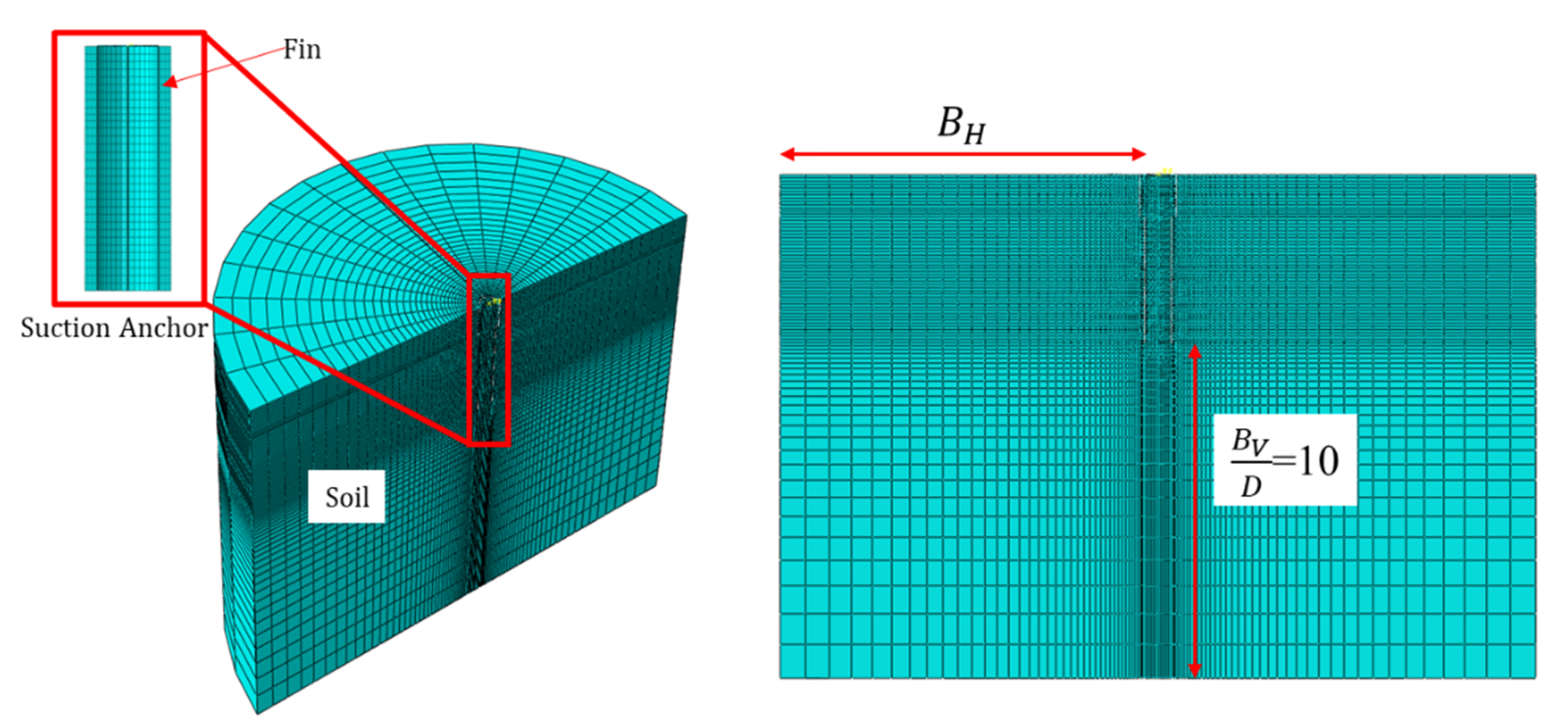
2.2. Models and Conditions

The finite element method is carried out using the commercial package Abaqus 2017. Considering the symmetry of the problem, only one-half of the finned suction anchors are modeled to save computational effort. The fin is modeled for half its thickness at the symmetry plane. The soil is modeled with an eight-node linear brick with a hybrid, constant pressure, reduced integration, and hourglass control formulation (element type: C3D8HR). The hybrid element is appropriate for simulating the incompressibility of clay, whose volume does not change under undrained conditions [37]. A thin soil (thickness, t = 50 mm) layer located adjacent to the surface of the finned suction anchor is modeled to represent the reduced strength of the soil due to thixotropy and consolidation [6]. The reduced strength ratio, α, of the soil is 0.65. The lateral boundaries of the soil model are constrained against both vertical and horizontal movements. The base is fully fixed (restrained in all directions), while the top surface is free of any constraints. A typical mesh and geometry of the soil model are shown in Figure 3. The soil comprises a finer mesh zone adjacent to the finned suction anchor and a coarser mesh near the soil boundary to reduce the simulation time without compromising the accuracy of the result. B V and B H represent the vertical and horizontal boundary extents from the skirt tip and the shaft of the suction foundation, respectively. The boundary with B H / D p 4.5 and B v / D p 4.5 is known to have a minimal effect on the bearing capacities [31]. Table 2 shows the soil dimension and number of elements adopted in the study for different L f / L s and L s / D p ratios. The diameter of the soil model is constant at 150 m ( B H / D = 14.5 ) while the soil depth varies from 57.5 to 75 m depending on the L s / D p ratio. The corresponding B V / D = 10 for L s / D p ratios of 1.5, 3, and 5 is constant. The finned suction anchors are modeled as discrete rigid bodies. A displacement-controlled method is adopted, and the load is applied at a reference point (RP) located at the top center of the lid. Numerical simulations are carried out in monotonic loadings under the conditions of free water by using effective stresses [38].
The soil–structure interfaces (between the suction foundation and soil) are modeled using a surface-to-surface contact algorithm. This algorithm allows gapping and slippage at the interface between the structure and soil by defining ‘hard contact’ and ‘frictional behavior’. The hard contact allows the interface separation when the normal stress at the interface becomes zero. The frictional behavior specifies a Coulomb friction law together with a limiting shear stress ( τ m a x ) along the soil–structure interface [39]. The interface between the foundation and the thin soil is assumed to have a frictional coefficient, α, of 0.65, following Supachawarote [6]. The internal surface is not assigned to any strength reduction [6]. No detachment between the foundation and the soil is allowed [6,35,37,40].

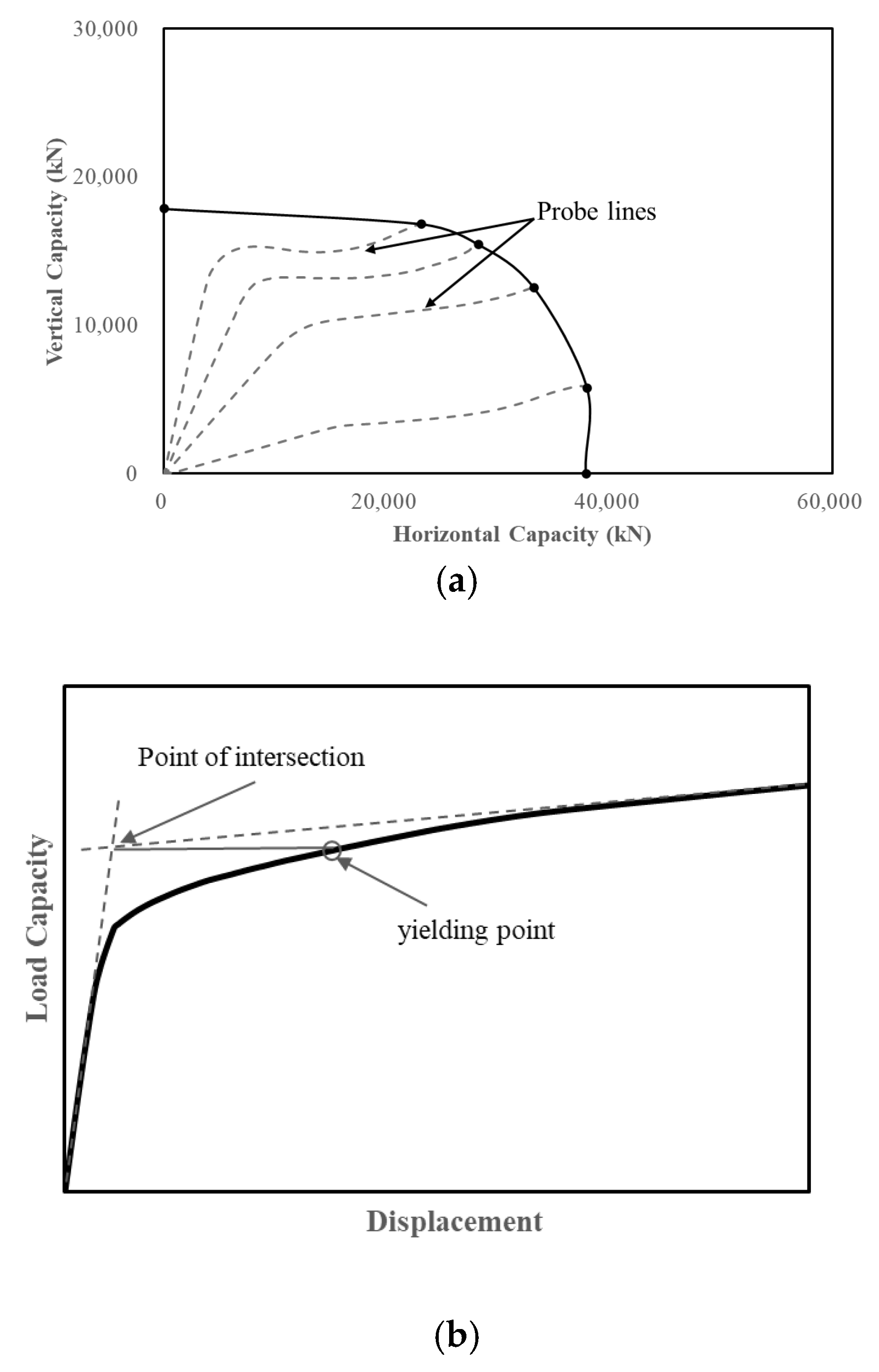
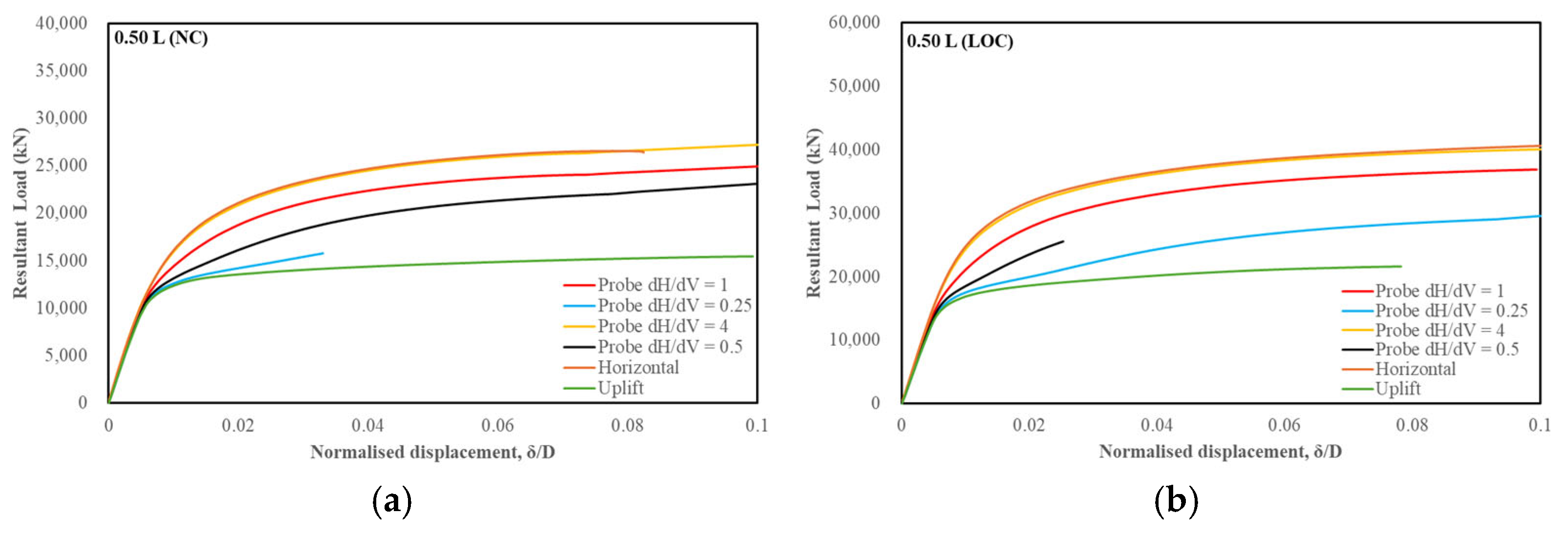
2.3. Determination of the Bearing Capacity and VH Failure Envelope

A series of displacement probe analyses are conducted to determine the bearing capacity envelope under V–H (Vertical–Horizontal) loadings. The VH failure envelope is constructed by plotting the vertical (V) and horizontal (H) load components from the corresponding load–displacement curves extracted at the reference point (RP). In the probe method, the vertical and horizontal displacements increased simultaneously at a constant dH/dV ratio. One loading path tracks around the capacity envelope and reaches one failure point on the capacity envelope [35] as shown in Figure 4a. By varying the dH/dV displacement ratio, failure points along the capacity envelope are obtained. The displacement probes dH/dV = 0, 0.25, 0.50, 1, and 4, and ∞ (pure horizontal displacement) are used in tracking the capacity envelope in all models. Pure vertical and horizontal probes are represented by ∞ and 0, respectively. In the probes (dH/dV = 0.25, 0.50, 1, and 4), the displacement is increased until it reaches a displacement of 10% (0.5 m) of the finned suction bucket, similar to the criterion with Kim et al. [41]. However, in cases wherein the displacement probes (dH/dV = 0.25, 0.50, 1, and 4) did not reach the specified criteria due to numerical convergence problems during simulation, the corresponding displacement probe is not plotted in the VH failure envelope.
On the other hand, the pure capacity load–displacement curve under ∞ and 0 may not reach its ultimate state (i.e., continued deformation at constant load). In addition, the load–displacement curve may follow a positive gradient in the load–displacement curve, particularly for higher L s / D p ratios [6] and finned suction anchors due to the continuous mobilization of the soil. In all cases, the ultimate vertical bearing capacity V u l t and ultimate horizontal bearing capacity H u l t are determined using the tangent intersection method as shown in Figure 4b [42,43]. The method plots two tangential lines along the initial stiff elastic region and plastic region of the load–displacement curve, and the load corresponding to the intersection point of the two lines is taken as the yielding point (bearing capacity). This method is also used by Hung et al. [37] and Kim et al. [44].

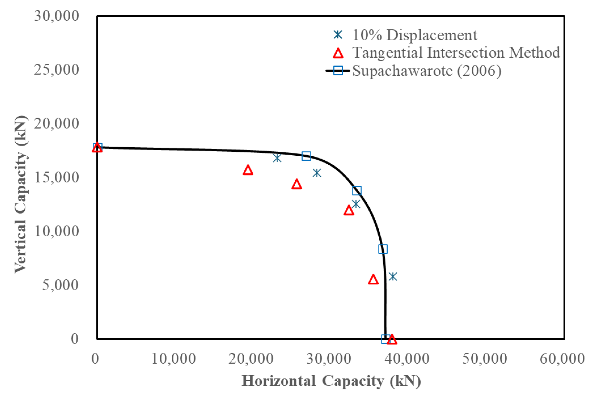
2.4. Validation of Numerical Modeling

The numerical modeling adopted in this study is validated by comparing the VH failure envelope for L s / D p = 5 with L f / L s = 0 (i.e., original suction anchors without fins) to the results reported by Supachawarote’s [6] shown in Figure 5. In Supachawarote’s [6] methodology, the failure capacity is defined as 20% of the anchor diameter if a constant load is not achieved, similar to Perumalsamy and Ranganathan [45]. The constitutive model employed for the undrained stress–strain response of clay is a linear elastic perfectly plastic model, incorporating the Von Mises failure criterion. The soil profile used in the validation consists of lightly over-consolidated (LOC) clay, with properties matching those adopted in this study with the Mohr-Coulomb failure criterion.
The comparison shows a discrepancy of 0.3% in uniaxial vertical capacities and 2.3% in uniaxial horizontal capacities using the tangential intersection method, which falls within a 95% confidence level. These differences arise primarily from variations in the method of determining the ultimate capacity (i.e., tangential method). Conversely, the ultimate capacity differs depending on the method to determine the bearing capacity (i.e., tangent intersection, log/log, hyperbolic, or 0.1B method) [43]. For inclined load capacities, the discrepancy is attributed to different failure load criteria; Supachawarote [6] uses 20% displacement of the suction anchor diameter, while this study adopts 10% displacement of the suction anchor diameter, which leads to lower capacity values, particularly when dH/dV > 0.25. In comparison, the inclined load capacities determined using the tangential intersection method are consistently lower than those obtained using the 10% displacement criterion. Notably, the 10% displacement criterion yields results that are more closely aligned with those reported by Supachawarote [6]. Therefore, the 10% displacement criterion is adopted throughout this study to ensure consistency and comparability. Despite these differences, the numerical analysis results align well with the failure envelope presented by Supachawarote [6], confirming the robustness of the modeling approach. Consequently, the numerical modeling approach used in this study is suitable for analyzing finned suction anchors.

3. Results

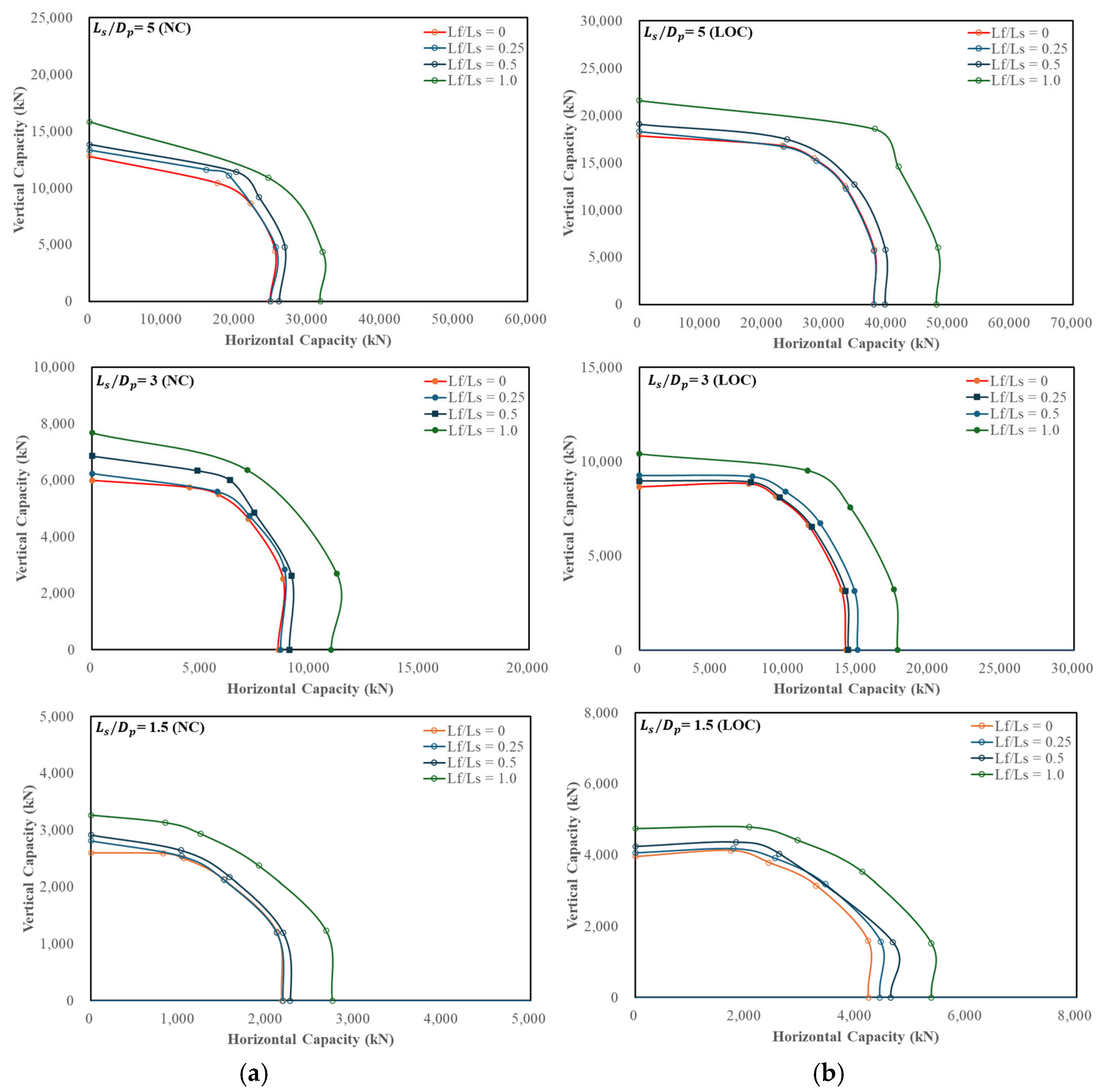
3.1. VH Failure Envelope

The VH failure envelopes for NC and LOC soils for different L s / D p and L f / L s ratios are shown in Figure 6. As previously mentioned, if the displacement probes (inclined load paths) do not reach the specified failure criterion (i.e., 10% displacement), those probes are excluded from the VH failure envelope. Figure 7 presents representative loading paths (dashed lines) from the numerical simulation for L f / L s = 1.0 VH failure envelope under NC and LOC conditions, corresponding to L s / D p = 5. An example of a load–displacement curve, expressed in terms of normalized displacement d/D and resultant load R, is shown in Figure 8 for L f / L s = 1.0 (also with L s / D p = 5). The resultant load R has a relationship with the vertical and horizontal components by the equation: R = V 2 + H 2 , wherein V and H are the corresponding vertical and horizontal loads extracted at the reference point (RP). The corresponding V and H values from the resultant load at 10% diameter (or 0.5 m resultant displacement) are selected as inclined failure points.
For NC conditions, certain displacement probes are missing from the envelope. The probe corresponding to dH/dV = 0.25 in the NC condition is not plotted for L s / D p = 5 across all L f / L s ratios. Additionally, the probes for dH/dV = 0.5 and dH/dV = 1 do not meet the 10% criterion for L f / L s = 1.0 and 0.25, respectively. For L s / D p = 3 and 1.5, some displacement probes (dH/dV = 0.25, 1.0) are missing for L f / L s = 0.25 and 1, respectively. In contrast, under LOC conditions, most displacement probes across the previous L s / D p and L f / L s ratios satisfy the 10% displacement criterion, allowing the plotting of nearly all failure points in the VH failure envelope. However, an exception exists for L s / D p = 5, where probes corresponding to dH/dV = 1 and 0.5 are not plotted for L f / L s = 0.5 and 1.0, respectively. Similarly, probes for dH/dV = 0.25 and dH/dV = 1.0 are missing for L s / D p = 3 and 1.5 under L f / L s = 1.0 and 0.5, respectively. Despite these exclusions, a VH failure curve is successfully obtained, demonstrating the load-bearing response of the finned suction anchors under combined vertical and horizontal loading. Additionally, the size of the VH failure envelope increases proportionally with the L f / L s ratio.

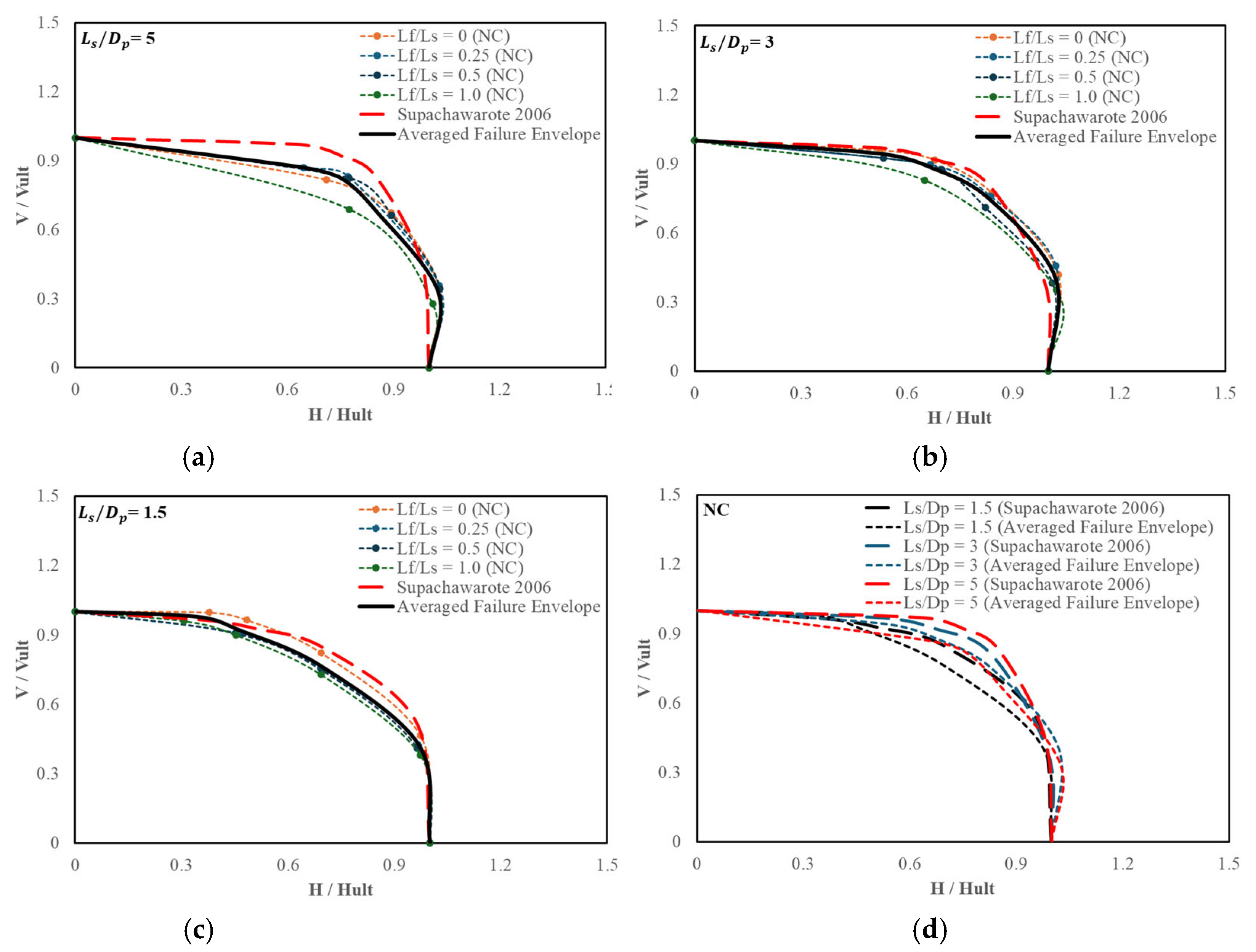
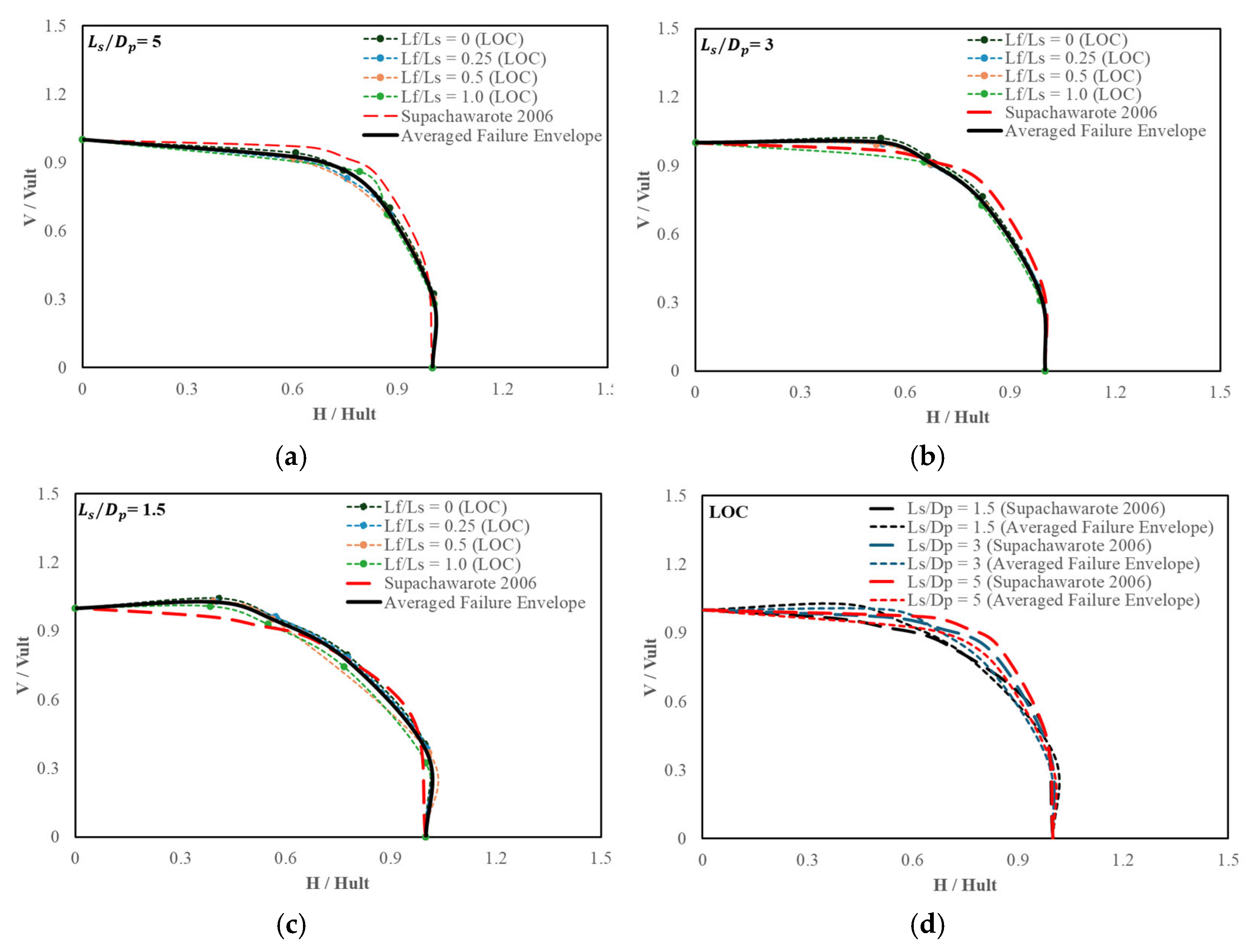
3.2. Normalized VH Failure Envelope

Normalized VH failure envelopes for different L s / D p ratios are shown in Figure 9 and Figure 10, for NC and LOC, respectively. The horizontal load component of the ultimate capacity H is normalized by the ultimate horizontal load capacity ( H u l t is the ultimate capacity under pure horizontal load) for the x-axis, and the vertical load component of the ultimate capacity ( V ) is normalized by the ultimate vertical load capacity ( V u l t is the ultimate capacity under pure vertical load) for the y-axis. The VH failure envelopes for different L f / L s ratios follow the same curved path. Additionally, the analytical solution for the VH failure envelope from Supachawarote [6], as shown in Equation (1), is included for comparison (red dashed line).
H H u l t a + V V u l t b = 1
where a = 0.5 + L s / D p and b = 4.5 L s / 3 D p . It should be noted that the above equation is applicable for normally consolidated soil with undrained shear strength proportional to depth. In Figure 9a–c, the averaged normalized envelopes (average of the failure envelopes of fins) derived from numerical analysis exhibit noticeable deviation from the analytical solution, primarily due to the absence of certain dH/dV ratios within the plotted data. Conversely, Figure 10a–c demonstrates strong correspondence with the analytical solution, with minor discrepancies observed at dH/dV = 0.25 and 4 in Figure 10c. Nevertheless, the average normalized VH failure envelopes follow the analytical solution with minimal alteration. Furthermore, Figure 9d and Figure 10d present the average failure envelopes for varying L s / D p ratios in comparison with the analytical solution. Smaller envelopes are seen with lower L s / D p ratios, while larger envelopes are seen with higher L s / D p ratios, similar to the analytical solution. This indicates that the failure envelope of the finned suction anchor is significantly influenced by the L s / D p ratio.

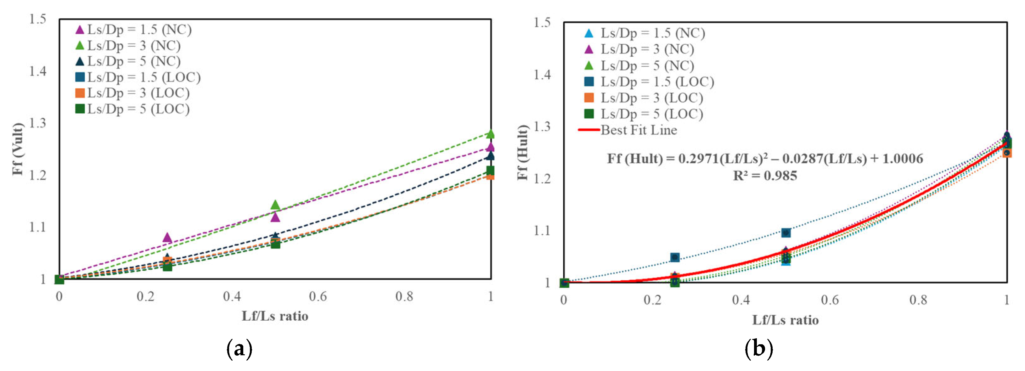
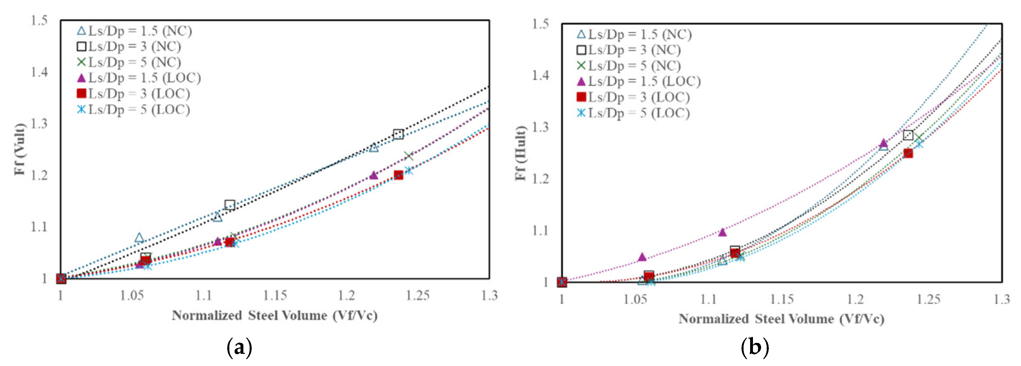
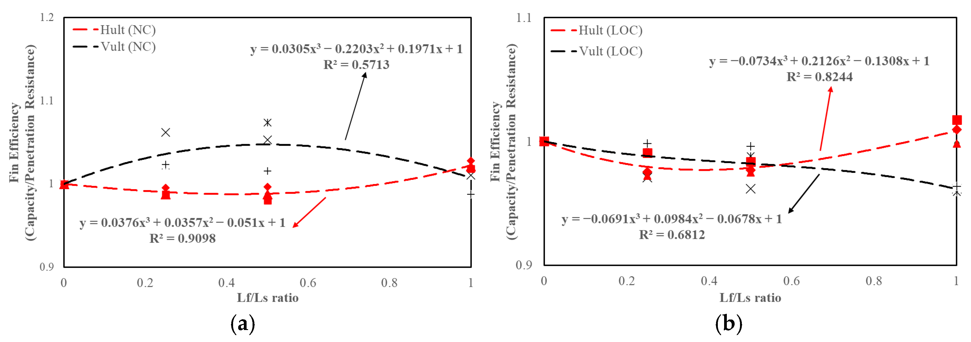
3.3. Fin Capacity in Vertical and Horizontal Loads

Figure 11a,b illustrates F f , defined as the ratio of the load capacity of the finned suction anchors to the conventional suction anchors, as a function of L f / L s ratio for various L s / D p ratios. In Figure 11a, a clear increasing trend is observed, with the magnitude of F f rising as the L f / L s ratio increases. However, this increase does not follow a consistent linear or exponential pattern, which can be attributed to the influence of the soil profile, as different soil conditions significantly affect the load-transfer mechanisms and, consequently, the fin-induced capacity enhancement. Conversely, Figure 11b reveals a more distinct trend in horizontal capacity, with F f showing a stronger correlation to fin geometry. To better capture this relationship, a best-fit curve with R2 = 0.985 has been introduced, approximating F f values for horizontal capacity across different L f / L s ratios. The equation follows the general equation y = a x 2 + b x + c where the coefficients a, b, and c are 0.2971, −0.0287, and 1.006, respectively. This curve underscores the nonlinear nature of capacity enhancement, reflecting the increasing contribution of the fins as L f / L s increases. The figures also illustrate the influence of the fin factor, showing minimal dependence on the L s / D p ratio.
Figure 12a,b shows the fin factor F f as a function of normalized steel volume for finned suction anchors. The normalized steel volume is defined as the ratio between the steel volume of the finned suction anchor, V f and the volume of the conventional suction anchor, V c . As expected, a higher F f corresponds to an increased steel volume. The normalized steel volume ranges from 1.05 to 1.24 for L f / L s = 0.25, 0.5, and 1.0. The fin factor for V u l t ranges from 1.04 to 1.28 under NC and from 1.02 to 1.20 under LOC. For H u l t , the fin factor ranges from 1.01 to 1.28 under NC and from 1.01 to 1.27 under LOC.

4. Discussion

The analysis of the VH failure envelope and the evaluation of the fin factor F f in vertical and horizontal loadings offer valuable insights into the enhanced performance of finned suction anchors, contributing to a broader understanding of finned suction anchors under VH loadings. The expansion of the VH failure envelope with increasing L f / L s ratios indicate the significant contribution of fins to the anchor’s load-bearing capacity. This enhancement arises from the increased passive resistance mobilized along the fin surfaces, which mitigates sliding, reduces tilting, and improves lateral stability by promoting better stress distribution and deeper load transfer into the surrounding soil. Additionally, higher capacity can be achieved at smaller displacements. The consistent path of the normalized VH failure envelopes, despite the addition of fins, further suggests that the inclusion of fins primarily enhances the magnitude of the load capacity without altering the overall VH failure envelope. This finding underscores the reliability of finned suction anchors in maintaining predictable failure paths under combined vertical and horizontal loading.
The fin factor, F f , quantifying the load capacity enhancement of the finned suction anchor relative to the conventional suction anchor is independent of L s / D p ratios for various L f / L s ratios, indicating that the enhancement is primarily governed by fin geometry rather than the suction anchor L s / D p ratio, with constant fin width and a number of fins. Also, the nonlinear increase in F f with higher L f / L s ratios emphasizes the complex interaction between fins and the surrounding soil, reflecting variations in load-transfer mechanisms in NC and LOC conditions. This behavior highlights the potential for further optimization of fin geometry to enhance suction anchor performance more effectively.
While it is proven that fins enhance the pullout capacity, it is also important to evaluate the efficiency of fins with penetration resistance (inside frictional resistance + outside frictional resistance + tip resistance) during the installation phase. Similarly to dynamically installed anchors (DIAs), where the addition of fins increases the penetration resistance [46], the impact of fins on the penetration resistance of finned suction anchors should be examined in terms of fin efficiency. The contribution of fins primarily adds to the outside frictional resistance and fin tip resistance. Fin efficiency is defined as the ratio of the increase in capacity (in terms of F f ) to the increase in penetration resistance of the finned suction anchor to the conventional suction anchor. A value greater than unity indicates that the fins contribute more to capacity than to penetration resistance, whereas a value less than unity suggests that penetration resistance outweighs the fins’ contribution to capacity. Figure 13 illustrates the fin efficiency trend for various L f / L s ratios across L s / D p = 1.5, 3, and 5. For LOC, the fin efficiency values range from 0.998 to 0.959 for V u l t and 0.972 to 1.017 for H u l t . Under NC, the fin efficiency values range from 1.07 to 0.98 for V u l t and 0.98 to 1.03 for H u l t . For V u l t , the fin efficiency decreases as L f / L s ratio increases in LOC except NC cased where fin efficiencies > 1 is observed. In contrast, the fin efficiency for H u l t is below 1 for L f / L s = 0.25 and 0.5 but exceeds 1 at L f / L s = 1.0 in both NC and LOC. Despite the inverse relationship between fin efficiency and L f / L s for vertical capacity in LOC, the addition of fins remains advantageous in terms of suction anchor dimensions, fabrication, and transportation constraints.
Similarly, the efficiency of fins in terms of capacity relative to steel volume is illustrated in Figure 14a,b. The vertical axis shows the ratio of the fin factor to the normalized steel volume, F f / ( V f / V c ) plotted against L f / L s ratios. A value greater than unity indicates that the fins contribute more to capacity than the associated increase in steel volume, whereas a value less than unity suggests that the added steel volume outweighs the fins’ contribution to capacity. As shown in the figures, F f / ( V f / V c ) is below unity at lower L f / L s ratios but exceeds unity as L f / L s approaches 1.0 for both V u l t and H u l t , highlighting that longer fins are more efficient in converting additional steel into usable capacity. Interestingly, efficiency gains are observed for V u l t under NC at smaller L f / L s ratios, indicating that vertical resistance can benefit from fins even when the added steel volume is limited. In contrast, H u l t shows lower efficiency at small fin lengths, suggesting that horizontal capacity is more dependent on fin development. These results suggest that the increase in steel volume is well balanced by the gain in capacity, particularly at L f / L s approaching 1.0, demonstrating that longer fins offer improved material efficiency.
These findings highlight the need to investigate additional factors that influence the effectiveness of finned suction anchors in offshore applications. While this study focuses on monotonic loading conditions, offshore structures are typically subjected to cyclic and dynamic loads from waves, currents, and wind. Future research should examine the performance of finned suction anchors under cyclic loading to assess potential degradation in load capacity and long-term stability. In addition, the performance of finned suction anchors during installation should be further analyzed. Moreover, structural analysis for the connection of fins is not carried out in this study, warranting further exploration to assess potential stress concentrations and structural integrity under different loading conditions and fin dimensions. While increased fin width enhances capacity, additional structural assessments are necessary to ensure sufficient rigidity during installation operations [1].

5. Conclusions

This study investigates the VH failure envelopes and capacity enhancement of finned suction anchors under various L s / D p and L f / L s ratios in normally consolidated (NC) and lightly over-consolidated (LOC) soil conditions through numerical modeling.
The results demonstrate that fin geometry significantly influences the load-bearing behavior of suction anchors under combined VH loading. The VH failure envelope expands with increasing L f / L s , indicating improved soil-foundation interaction, greater passive soil resistance, and enhanced horizontal load-carrying capacity due to longer fins. The normalized VH failure envelopes exhibit consistent alignment across different L s / D p and L f / L s ratios, following a similar curve path. This suggests that while fin length increases load capacity, it does not substantially alter the overall shape of the VH failure envelope. Comparisons with Supachawarote’s [6] analytical solution further support this trend, despite variations in failure criteria and constitutive modeling.
Capacity enhancement due to fins is quantified using the fin factor (ratio of finned suction anchor capacity to conventional suction anchor capacity), F f which indicates an increase in both vertical and horizontal load capacities with higher L f / L s ratios. The results show that F f is primarily influenced by L f / L s with minimal dependence on L s / D p . A nonlinear trend emerges in increasing L f / L s , attributed to the complex interaction between soil conditions and load-transfer mechanisms. A best-fit curve introduced for horizontal capacity further highlights the nonlinear relationship between L f / L s and F f . Fin efficiency, ratio between the increase in capacity to the increase in penetration resistance due to the fins, exhibits an inverse correlation with L f / L s in vertical capacity and horizontal capacity, except for the horizontal capacity at L f / L s = 1.0 and vertical capacity of NC. The additional steel volume introduced by the fins is more efficiently utilized in longer fins, particularly when L f / L s approaches 1.0, where the corresponding capacity gain is more significant.
Ongoing experimental investigations are being conducted to validate and complement the numerical results presented in this study. Future research should further refine finned suction anchor designs by investigating the effects of varying fin configurations, soil profiles, cyclic loading conditions, and structural design to optimize foundation performance in offshore environments. A parametric study should be conducted for the effects of various soil parameters to develop engineering approximations for the failure envelope.

Author Contributions

Conceptualization, Y.W.C.; methodology, A.G.; software, A.G.; validation, A.G. and Y.W.C.; formal analysis, A.G.; investigation, A.G.; resources, A.G.; data curation, A.G.; writing—original draft preparation, A.G.; writing—review and editing, Y.W.C.; visualization, Y.W.C.; supervision, Y.W.C.; project administration, Y.W.C.; funding acquisition, Y.W.C. All authors have read and agreed to the published version of the manuscript.

Funding

This research was funded by the Korea Institute of Energy Technology Evaluation and Planning (KETEP) grant and the Ministry of Trade, Industry & Energy (MOTIE) of the Republic of Korea (RS-2024-00456423 and No. RS-2022-KP002820). This work was supported by the National Research Foundation of Korea (NRF) grant funded by the Korea Government (MSIT) (RS-2024-00406320).

Data Availability Statement

The original contributions presented in this study are included in the article. Further inquiries can be directed to the corresponding author.

Conflicts of Interest

The authors declare no conflicts of interest.

Abbreviations

The following abbreviations are used in this manuscript:
DIADynamically installed anchors
FPSOFloating production, storage, and offloading
VHVertical–horizontal
NCNormally consolidated soil
LOCLightly over-consolidated soil

References

  1. Garcia, P.C.; Panayides, S. Effect of Fins on Combined Loaded Suction Caisson in Deepwater Clay Soils. A Numerical Analysis. In Proceedings of the Offshore Technology Conference, Houston, TX, USA, 16–19 August 2021; p. D011S012R006. [Google Scholar] [CrossRef]
  2. Randolph, M.F.; Gourvenec, S. Offshore Geotechnical Engineering; Spon Press: London, UK; New York, NY, USA, 2011. [Google Scholar]
  3. Silva-González, F.; Heredia-Zavoni, E.; Valle-Molina, C.; Sánchez-Moreno, J.; Gilbert, R.B. Reliability study of suction caissons for catenary and taut-leg mooring systems. Struct. Saf. 2013, 45, 59–70. [Google Scholar] [CrossRef]
  4. Fu, D.; Zhou, Z.; Yan, Y.; Pradhan, D.L.; Hennig, J. A method to predict the torsional resistance of suction caisson with anti-rotation fins in clay. Mar. Struct. 2021, 75, 102866. [Google Scholar] [CrossRef]
  5. Kim, S.; Choo, Y.W.; Kim, J.-H.; Kim, D.-S.; Kwon, O. Pullout resistance of group suction anchors in parallel array installed in silty sand subjected to horizontal loading—Centrifuge and numerical modeling. Ocean Eng. 2015, 107, 85–96. [Google Scholar] [CrossRef]
  6. Supachawarote, C. Inclined Load Capacity of Suction Caisson in Clay. Ph.D. Thesis, The University of Western Australia, Perth, Australia, 2006. [Google Scholar]
  7. Lee, J.; Do, J. Effects of the Installation Method, Loading Condition, and Failure Mechanism on the Behavior of Suction Piles under Monotonic Horizontal Loading. J. Mar. Sci. Eng. 2021, 9, 1333. [Google Scholar] [CrossRef]
  8. Tran, M.N. Installation of Suction Caissons in Dense Sand and the Influence of Silt and Cemented Layers. 2005. Available online: https://ses.library.usyd.edu.au/handle/2123/4064 (accessed on 5 February 2025).
  9. Chatzivasileiou, G.I. Installation of Suction Caissons in Layered Sand. 2014. Available online: https://repository.tudelft.nl/record/uuid:bf2f9c3c-dc96-4487-bb73-784d90f7ac33 (accessed on 24 January 2025).
  10. Senders, M.; Randolph, M.; Gaudin, C. Theory for the Installation of Suction Caissons in Sand Overlaid by Clay. In Proceedings of the Offshore Site Investigation and Geotechnics-Confronting New Challenges and Sharing Knowledge, London UK, 11–13 September 2007; pp. 429–438. [Google Scholar]
  11. Cotter, O.J.; Byrne, B.W.; Houlsby, G.T. Installation of suction caissons for offshore renewable energy structures. In Frontiers in Offshore Geotechnics II; CRC Press: Boca Raton, FL, USA, 2010; ISBN 978-0-429-21303-8. [Google Scholar]
  12. Lee, J.; Aubeny, C.P. Optimal load attachment of a deeply embedded ring anchor in clay. Int. J. Geo-Eng. 2024, 15, 24. [Google Scholar] [CrossRef]
  13. Choo, Y.W.; Kim, D.-J.; Youn, J.-U.; Hossain, M.S.; Seo, J.; Kim, J.-H. Behavior of a Monopod Bucket Foundation Subjected to Combined Moment and Horizontal Loads in Silty Sand. J. Geotech. Geoenviron. Eng. 2021, 147, 04021025. [Google Scholar] [CrossRef]
  14. Lee, M.J.; Gilo, A.; Park, S.J.; Choo, Y.W. Centrifuge model test on the bearing capacity of suction anchors subjected to monotonic and cyclic inclined pullout loads in clay. KSCE J. Civ. Eng. 2025, 29, 100113. [Google Scholar] [CrossRef]
  15. Basha, A.M.; Eldisouky, E.A. Effect of eccentric loads on the behavior of circular footing with/without skirts resting on sand soil. Int. J. Geo-Eng. 2023, 14, 13. [Google Scholar] [CrossRef]
  16. Raju, K.V.S.B.; Lakshmi, V. Pullout and oblique pullout resistance of enlarged base piles in geogrid reinforced sand. Int. J. Geo-Eng. 2025, 16, 12. [Google Scholar] [CrossRef]
  17. Sakr, M.; Nasr, A.; Khaffaf, M.; Basha, A. Behavior of under-reamed piles under inclined uplift loads in sand. Int. J. Geo-Eng. 2025, 16, 9. [Google Scholar] [CrossRef]
  18. Park, S.; Kim, G.-Y.; Chang, I. Experimental study on the effect of surface-projected conditions on the mechanical behavior of pile embedded in sand. Int. J. Geo-Eng. 2024, 15, 22. [Google Scholar] [CrossRef]
  19. Achmus, M.; Kuo, Y.-S.; Abdel-Rahman, K. Behavior of monopile foundations under cyclic lateral load. Comput. Geotech. 2009, 36, 725–735. [Google Scholar] [CrossRef]
  20. Deshmukh, R.R.; Sharma, V.K. Three dimensional computer simulation of cushiontaper finned pile foundation for offshore wind turbine. In Proceedings of the International Geotechnical Engineering Conference on Sustainability in Geotechnical Engineering Practices and Related Urban Issues, Mumbai, India, 23–24 September 2016. [Google Scholar]
  21. Dührkop, J.; Grabe, J. Laterally Loaded Piles with Bulge. J. Offshore Mech. Arct. Eng. 2008, 130, 041602. [Google Scholar] [CrossRef]
  22. Nasr, A.M.A. Experimental and theoretical studies of laterally loaded finned piles in sand. Can. Geotech. J. 2014, 51, 381–393. [Google Scholar] [CrossRef]
  23. Pei, T.; Qiu, T. A Numerical Investigation of Laterally Loaded Steel Fin Pile Foundation in Sand. Int. J. Geomech. 2022, 22, 04022102. [Google Scholar] [CrossRef]
  24. Peng, J.-R.; Rouainia, M.; Clarke, B.G. Finite element analysis of laterally loaded fin piles. Comput. Struct. 2010, 88, 1239–1247. [Google Scholar] [CrossRef]
  25. Abouzaid, A.; El Naggar, M.H.; Drbe, O. Comprehensive Evaluation of Lateral Performance of Innovative Post in Sand. Appl. Sci. 2024, 14, 2442. [Google Scholar] [CrossRef]
  26. Krishnanunni, K.T.; Rathod, D. The numerical investigation on the efficacy of a laterally loaded finned pile installed in a two-layered sandy slope. Int. J. Geotech. Eng. 2025, 19, 213–228. [Google Scholar] [CrossRef]
  27. Qin, S.; Lee, J.; Aubeny, C.P. Fatigue performance of the Deeply Embedded Ring Anchor. Int. J. Geo-Eng. 2024, 15, 23. [Google Scholar] [CrossRef]
  28. Fu, D.; Zhou, Z.; Pradhan, D.L.; Yan, Y. Bearing Performance of Finned Suction Caissons under Combined VHMT Loading in Clay. J. Geotech. Geoenviron. Eng. 2024, 150, 04024031. [Google Scholar] [CrossRef]
  29. Garcia, P.C.; Branco, L.; Fernandes, B.; Tsetoulidis, C.; Mader, M.; Orejuela, D.; Serra, E.; Panayides, S. Torpedo Piles and Suction Piles: Geotechnical Analysis and Installation Experiences in Seek for Optimal Anchoring System in Deepwater Clay Soils. In Proceedings of ASME 2024 43rd International Conference on Ocean, Offshore and Arctic Engineering, Singapore, 9–14 June 2024; p. V008T10A010. [Google Scholar] [CrossRef]
  30. Garcia, P.C.; Gerometta, G.; Panayides, S. Geotechnical and Structural Design Considerations for Finned Piles—Numerical and Analytical Results. In Proceedings of the 32nd International Ocean and Polar Engineering Conference, Shanghai, China, 5–10 June 2022. [Google Scholar]
  31. Hung, L.C.; Kim, S.R. Evaluation of vertical and horizontal bearing capacities of bucket foundations in clay. Ocean Eng. 2012, 52, 75–82. [Google Scholar] [CrossRef]
  32. Nguyen, A.-D.; Nguyen, V.-T.; Kim, Y.-S. Finite element analysis on dynamic behavior of sheet pile quay wall dredged and improved seaside subsoil using cement deep mixing. Int. J. Geo-Eng. 2023, 14, 9. [Google Scholar] [CrossRef]
  33. Yasser, F.; Altahrany, A.; Elmeligy, M. Numerical investigation of the settlement behavior of hybrid system of floating stone columns and granular mattress in soft clay soil. Int. J. Geo-Eng. 2022, 13, 12. [Google Scholar] [CrossRef]
  34. Hemeda, S. Geotechnical modelling and subsurface analysis of complex underground structures using PLAXIS 3D. Int. J. Geo-Eng. 2022, 13, 9. [Google Scholar] [CrossRef]
  35. Yun, G.; Bransby, M.F. The horizontal-moment capacity of embedded foundations in undrained soil. Can. Geotech. J. 2007, 44, 409–424. [Google Scholar] [CrossRef]
  36. Taiebat, H.A.; Carter, J.P. Numerical studies of the bearing capacity of shallow foundations on cohesive soil subjected to combined loading. Géotechnique 2000, 50, 409–418. [Google Scholar] [CrossRef]
  37. Hung, L.C.; Kim, S.-R. Evaluation of combined horizontal-moment bearing capacities of tripod bucket foundations in undrained clay. Ocean Eng. 2014, 85, 100–109. [Google Scholar] [CrossRef]
  38. Gilo, A.; Lee, M.J.; Wook, C.Y. Numerical Analysis of the Effect of an Inverted Cone Angle on the Penetration Behavior of the Jack-Up Leg Foundation for Offshore Wind Turbines in Uniform Clay. J. Ocean Eng. Technol. 2024, 38, 438–448. [Google Scholar] [CrossRef]
  39. Choo, Y.W.; Seo, J.; Kim, Y.-N.; Goo, J.; Kim, Y. Numerical Studies on Piled Gravity Base Foundation for Offshore Wind Turbine. Mar. Georesour. Geotechnol. 2016, 34, 729–740. [Google Scholar] [CrossRef]
  40. Gourvenec, S. Effect of embedment on the undrained capacity of shallow foundations under general loading. Géotechnique 2008, 58, 177–185. [Google Scholar] [CrossRef]
  41. Kim, S.; Choo, Y.W.; Kim, D.-S. Pullout Capacity of Horizontally Loaded Suction Anchor Installed in Silty Sand. Mar. Georesour. Geotechnol. 2016, 34, 87–95. [Google Scholar] [CrossRef]
  42. Mansouri, M.; Imani, M.; Fahimifar, A. Ultimate bearing capacity of rock masses under square and rectangular footings. Comput. Geotech. 2019, 111, 1–9. [Google Scholar] [CrossRef]
  43. Cerato, A.; Lutenegger, A.J. Scale Effects of Shallow Foundation Bearing Capacity on Granular Material. J. Geotech. Geoenviron. Eng. 2007, 133, 1192–1202. [Google Scholar] [CrossRef]
  44. Kim, D.-J.; Choo, Y.W.; Kim, J.-H.; Kim, S.; Kim, D.-S. Investigation of Monotonic and Cyclic Behavior of Tripod Suction Bucket Foundations for Offshore Wind Towers Using Centrifuge Modeling. J. Geotech. Geoenviron. Eng. 2014, 140, 04014008. [Google Scholar] [CrossRef]
  45. Perumalsamy, K.; Ranganathan, S. Single pile in cohesionless soil in sloping ground under lateral loading. Int. J. Geo-Eng. 2022, 13, 8. [Google Scholar] [CrossRef]
  46. Choo, Y.W.; Falcon, S.S.; Kim, Y.; Hossain, M.S. Performance of a dynamically installed fish anchor in cohesionless soils. Ocean Eng. 2022, 260, 111995. [Google Scholar] [CrossRef]
Figure 1. Different L f / L s ratios used in the analyses: (a) L f / L s = 0; (b) L f / L s = 0.25; (c) L f / L s = 0.50; (d) L f / L s = 1.0.
Jmse 13 01104 g001
Figure 2. Undrained shear strength, S u profiles in clay: (a) normally consolidated; and (b) lightly over-consolidated (right).
Jmse 13 01104 g002
Figure 3. Mesh and boundary conditions used in the numerical analyses.
Jmse 13 01104 g003
Figure 4. (a) Failure envelope and probe lines; and (b) tangential intersection method to determine ultimate capacity.
Jmse 13 01104 g004
Figure 5. VH failure envelope for L s / D p = 5 with L f / L s = 0 against analytical solution from Supachawarote [6].
Jmse 13 01104 g005
Figure 6. VH failure envelopes for various L s / D p and L f / L s ratios in (a) NC and (b) LOC.
Jmse 13 01104 g006
Figure 7. Example of loading paths (dashed lines) in VH failure envelopes for L s / D p = 5 ( L f / L s = 1.00) in (a) NC and (b) LOC.
Jmse 13 01104 g007
Figure 8. Example of a load–displacement curve for L s / D p = 5 ( L f / L s = 0.50) in (a) NC and (b) LOC.
Jmse 13 01104 g008
Figure 9. Normalized VH failure envelopes for various L f / L s ratios in NC against Supachawarote [6]: (a) L s / D p = 5; (b) L s / D p = 3; (c) L s / D p = 1.5; and (d) averaged failure envelopes.
Jmse 13 01104 g009
Figure 10. Normalized VH failure envelopes for various L f / L s ratios in LOC against Supachawarote [6]: (a) L s / D p = 5; (b) L s / D p = 3; (c) L s / D p = 1.5; and (d) averaged failure envelopes.
Jmse 13 01104 g010
Figure 11. Fin factor against L f / L s ratio trend in (a) V u l t ; (b) H u l t .
Jmse 13 01104 g011
Figure 12. Fin factor against normalized steel volume in (a) V u l t ; (b) H u l t .
Jmse 13 01104 g012
Figure 13. Fin efficiency in terms of penetration resistance in V u l t and H u l t for (a) NC; (b) LOC.
Jmse 13 01104 g013
Figure 14. Fin efficiency in terms of steel volume for V u l t and H u l t for (a) NC; (b) LOC.
Jmse 13 01104 g014
Table 1. Soil parameters used in this study.
Soil ParameterNCLOC
Undrained   Shear   Strength ,   S u (kPa)1.25z 10  for  z < 5  m
for  z 5 m
Poisson s   ratio ,   ν 0.490.49
Effective   unit   weight   of   soil   γ k N m 3 67.2
Earth   Pressure   Coefficient ,   K 0 0.55 1.0   ( z < 5 m)
0.65   ( z 5 m)
Table 2. Soil dimension and no. of elements adopted in this study.
L s / D p Parameters of Models L f / L s
00.250.501.0
1.5Soil model diameter (m)150
Soil model depth (m)57.5
Number of elements27,95247,89646,68846,528
3Soil model diameter (m)150
Soil model depth (m)65
Number of elements38,70464,73664,57664,256
5Soil model diameter (m)150
Soil model depth (m)75
Number of elements52,14487,31687,05686,416
Disclaimer/Publisher’s Note: The statements, opinions and data contained in all publications are solely those of the individual author(s) and contributor(s) and not of MDPI and/or the editor(s). MDPI and/or the editor(s) disclaim responsibility for any injury to people or property resulting from any ideas, methods, instructions or products referred to in the content.

