Abstract
To mitigate the issue of high-pitch natural frequency in V-shaped floating offshore wind turbines (FOWTs), a novel semi-submersible floater design, termed NewSemi, is proposed in this study. The structural performance of the NewSemi floater is compared with that of two existing 5 MW FOWTs, namely, the V-shaped and Braceless. Frequency domain analysis demonstrates that the NewSemi floater exhibits the most favorable response amplitude operator (RAO) in the pitch direction, along with superior damping characteristics. The result reveals a 16.44% reduction in pitch natural frequency compared to the V-shaped floater. Time-domain analysis under extreme conditions reveals 14.6% and 65.2% reductions in mean surge and pitch motions compared to Braceless FOWT, demonstrating enhanced stability. In addition, compared with the V-shaped FOWT, it exhibits smaller standards and deviations in surge and pitch motion, with reductions of 11.3% and 31.9%, respectively. To accommodate the trend toward larger FOWTs, an optimization procedure for scaling up floater designs is developed in this study. Using a differential evolution algorithm, the optimization process adjusts column diameter and spacing while considering motion response and steel usage constraints. The NewSemi floater is successfully scaled from 5 MW to 10 MW, and the effects of this scaling on motion and structural dynamics are examined. Numerical analysis indicates that as turbine size increases, the motion response under extreme sea conditions decreases, while structural dynamic responses, including blade root torque, rotor thrust, tower-base-bending moment and axial force, significantly increase. The maximum values of blade root torque and tower-base-bending moment increase by 10.4 times and 3.95 times in different load cases, respectively, while the mooring forces remain stable. This study offers practical engineering guidance for the design and optimization of next-generation floating wind turbines, enhancing their performance and scalability in offshore wind energy applications.
1. Introduction
Driven by the urgent demand for renewable electricity generation, offshore wind energy has grown rapidly and significantly in recent years. A large number of wind farms have been constructed worldwide, primarily situated in coastal shallow-water regions. However, as suitable nearshore sites become increasingly scarce, future wind farms will inevitably need to move further from shore into deeper waters [1]. One of the primary challenges hindering the commercial development and operation of wind energy in medium and deep-water seas is the high cost.
To control cost, the widely-used monopile foundation, typically employed in shallow seas less than 60 m deep, becomes impractical in deeper waters. A more promising alternative is the floating foundation [2]. As a result, recent research has increasingly focused on developing floating foundation concepts. Based on the principle of hydrostatic stability, floating foundations can be classified into four types: Spar, TLP, Barge and Semisubmersibles [3,4,5]. The Spar floater has the simplest cylindrical structure, achieving hydrostatic stability through deep drafts and a low center of gravity. The TLP’s stability is provided by a tensioned mooring system, while both semi-submersible floaters are stabilized by large water plane areas [6]. Among these, semi-submersible floaters are considered the most suitable for mid- and deep-sea applications. Numerous studies have demonstrated that semi-submersibles offer superior hydrodynamic performance and are also easier to be installed and transported. Typically, a semi-submersible consists of multiple columns connected by braces, with the wind turbine mounted on one of the columns [7,8]. The OC4-Semi is a well-known semi-submersible wind turbine floater that comprises three side columns connected to a central column by braces, with the wind turbine mounted on the central column [9]. Another typical concept, the WindFloat, is designed with three side columns to reduce steel weight. The three columns are also connected by braces [10].
The hydrodynamic performance and stability of both the OC4-Semi and WindFloat concepts have proven to be satisfactory, with a prototype of WindFloat already tested. However, there is ongoing debate regarding column connection. At a given joint, a column could be connected by several braces, creating complex and expensive welding issues. Additionally, the fatigue life of these joints is a critical concern due to stress concentration [11]. To address these challenges, several Braceless concepts have been proposed [12]. Luan proposed a four-column semi-submersible platform concept named CSC, which features a layout similar to the OC4-semi, with columns connected by pontoons rather than braces. A model test conducted by Luan et al. [12] confirmed the rationality in terms of its hydrodynamic performance and structural strength. A similar layout has been designed and thoroughly analyzed by Li et al. [13] for a 10 MW FOWT, focusing on internal forces/moment/stresses. Based on the theory of potential flow and empirical values of viscous damping, a study was conducted on the hydrodynamic characteristics of the proposed floating wind turbine system with integrated wave energy device by Shi et al. [14,15]. Karimirad [16] studied a three-column Braceless concept named V-shaped and examined its applicability in various water depths. This design significantly reduces cost but exhibits asymmetric stability and a short pitch nation period. Additionally, Cao et al. [17] designed a four-column semi-submersible floater with three tilted side columns to increase water plane moments for enhancing intact stability.
The concepts proposed in the aforementioned research have been validated through extensive numerical simulations and model tests. Furthermore, some demonstration projects have confirmed the feasibility of the semi-submersible FOWT concepts. In 2013, Japan launched the Fukushima FORWARD 2 MW FOWT demonstration project [18]. In 2018, France completed the Floatgen 2 MW FOWT demonstration project [19]. More recently, in 2021, China deployed its first FOWT, “Sanxia Yinling”, at the Yangjiang Shabahai offshore wind farm in the Three Gorges region. This installation, equipped with a semi-submersible foundation and a 5.5 MW wind turbine, became the world’s first typhoon-resistant FOWT [20]. Notably, recent advancements in platform design include those of Gonçalves et al. [21], who proposed a multi-column FOWT with tunable heave plates to mitigate flow-induced motions through vortex shedding suppression, and those of Nagumo et al. [22], who developed a lightweight concept integrating guy-wire-supported towers and single-point mooring to address structural flexibility in shallow waters. However, most of the studies, experiments, and prototypes above utilized wind turbines with capacities of 5 MW or less, limiting their commercial viability due to cost constraints. A challenge remains in scaling up these designs for larger-capacity wind turbines. Leimeister et al. [23] discussed the complexities of upgrading the process of a semi-submersible wind turbine floater, highlighting that upgrading cannot be achieved simply by scaling up existing small wind turbines. Critical factors such as coupled dynamic motion, wave interaction, low-frequency response, and mooring systems must be considered to ensure the floater’s performance at larger scales.
For FOWTs, the natural period of the platform must be kept away from the wave period to prevent resonance. Resonance occurs when the natural period of the platform approaches the wave period, leading to a significant amplification of the platform’s motion amplitude [24]. This phenomenon can exceed the design limits of the platform, posing significant challenges to the structural integrity and operational safety of the system. In FOWT systems, large pitch motion natural frequencies pose significant resonance risks, while increased pitch amplitudes and frequencies lead to pronounced power output fluctuations, as demonstrated in Wen et al.’s research [25], which shows that the amplitude of power fluctuations is directly proportional to the pitch amplitude and frequency. In the context of frequent extreme sea conditions in the South China Sea, excessive pitch motion complicates turbine control due to the need for advanced strategies to manage power output and aerodynamic load fluctuations. Moreover, excessive pitch motion directly compromises structural stability. Therefore, optimizing the hydrodynamic performance during the floating platform design phase is essential to reduce the pitch natural frequency, thereby enhancing the operational stability and safety of FOWTs in harsh marine environments.
To mitigate this risk, the design of floating offshore wind turbines must ensure that the natural period of the platform is decoupled from the dominant wave periods. Typically, the peak spectral period of ocean waves ranges from 3 to 20 s. Therefore, the design process must incorporate parameter optimization to avoid resonance within this range. This can be achieved through careful adjustments of the floating platform’s geometry, mass distribution, and mooring system stiffness. By strategically tuning these parameters, the natural period of the platform can be shifted outside the critical wave period range, thereby minimizing the risk of resonance and ensuring the platform’s stability and safety in dynamic marine environments. In addition to considering the initial stage of float design for floating wind turbines, some researchers have combined floating wind turbines with wave energy generation devices to reduce the overall structural natural frequency, Payam et al. [26] propose a method to reduce the natural period of FOWTs by integrating Oscillating Water Columns (OWCs) into the substructure of a semi-submersible FOWTs. The results indicate that the integration of OWCs can effectively shift the natural periods of certain modes, such as roll and pitch, and reduce the resonant amplitudes, thereby improving the stability and safety of the FOWTs, but adding OWC devices may bring cost issues. Furthermore, some scholars have applied the tuned mass dampers widely used in the construction industry to the field of offshore floating wind power. Lu et al. [27] installed tuned mass dampers (TMDs) on floating offshore wind turbines (FOWTs) to reduce the system’s natural frequency by adjusting stiffness and damping coefficients. While effective, this approach introduces additional costs and technical challenges compared to direct FOWTs design optimization.
Existing semi-submersible designs (e.g., OC4-Semi, WindFloat) face challenges such as brace-induced stress concentrations and high fabrication costs. The V-shaped concept, while cost-effective, suffers from asymmetric stability and pitch resonance risks. This study introduces the NewSemi floater, which uniquely integrates three columns with pontoons to decouple pitch natural frequencies from dominant wave spectra, addressing a critical gap for FOWTs deployed in the South China Sea. And we have conducted a comprehensive comparative analysis of the various conceptual types of floating wind turbines proposed. Furthermore, the proposed scaling framework overcomes limitations in prior studies by systematically optimizing column spacing and diameter to accommodate larger turbines—a vital contribution given the industry’s shift toward 10 MW systems.
This paper is organized as follows: Section 2 presents the numerical methods used in this study. Section 3 describes the basic concept of the 5 MW floater and the scaling design for the 10 MW floater. Section 4 compares the V-shaped, NewSemi, and Braceless 5 MW FOWTs, verifying the advantages of the NewSemi floater through frequency and time domain analyses. Section 5 analyzes the NewSemi 5 MW and 10 MW FOWTs, examining the impact of scaling on wind turbine performance in both domains.
2. Theory Background
2.1. Coupled Motion Equation of the FOWT in the Time Domain
Based on Newton’s second law and Cummings’ theory, the motion equation of the FOWT system can be expressed as in Equation (1) [28].
where is the mass matrix of the FOWT, is the added mass matrix at infinite frequency, and D1 and D2 are the linear and quadratic damping matrices, respectively. is the retardation function, which can be derived from the frequency-dependent added mass or potential damping. represents the hydrostatic restoring force, and is the vector of other forces acting on the FOWT, which includes the following components in this study, as shown in Equation (2) [29].
where is the wind force, is the linear wave excitation force, is the second-order excitation force, and is the force from the mooring line. It should be noted that the definitions of nomenclature, Greek symbols, subscripts, superscripts, and acronyms are presented in Table A1 in Appendix A.
2.2. Hydrodynamic Load
For large floating structures, the structure’s presence impacts fluid particle movement, making the potential flow effect significant. This effect comprises diffraction and radiation. Diffraction affects the incoming wave field around a stationary structure, while radiation results from the structure’s movement in a stationary fluid. Three-dimensional potential flow theory is used to calculate the wave force when the potential flow effect is significant [30].
It is assumed that the water is an incompressible, non-viscous, and non-swirling ideal fluid. Under these conditions, the fluid motion has potential, and the velocity potential satisfies the Laplace equation.
The velocity potential satisfies the linearized boundary conditions on the free surface:
The boundary conditions are satisfied at the bottom of the sea (flat bottom):
On the floater surface, the object’s surface condition is satisfied:
where and are the generalized velocity in the plane motion and the generalized normal vector corresponding to the motion mode of a point on the plane, respectively. Since the governing equation and boundary conditions are linearized, the velocity potential satisfies the superposition principle and can be decomposed into incident potential, diffraction potential and radiation potential [31].
where is the velocity potential of the incident wave; is the diffraction potential; is the radiation potential. Assuming that the incident wave is a simple harmonic wave, the analytic solution for the incident potential can be expressed as follows:
where is the frequency of the incident wave, is the amplitude of the incident wave, and is the real part. For diffraction potential and radiation potential, only analytical solutions for simple geometric objects exist due to the influence of surface conditions in the boundary conditions. In contrast, complex offshore structures require numerical methods. The boundary element method is commonly used to solve the integral equation.
For the diffraction potential and radiation potential, the integral equation between Green’s function and the velocity potential is first established. When Green’s function satisfies the wavy free water condition, the object surface integral equation is as follows [32]:
where is Green’s function; is the solid angle coefficient; is the wet area of the object’s surface in still water; is the unit normal vector of the object’s surface, indicating that the fluid is positive; is the general direction.
Then, the object surface is discretized into several small elements using the boundary element method. It is assumed that the velocity potential at any point inside each small element can be expressed as a polynomial of the velocity potential at the nodes of the element. The linear equations for the node velocity potentials are established using either the coordination method or the Galerkin method [33].
The diffraction potential and radiation potential can be obtained by solving the equations numerically. Through linearized Bernoulli equation, the fluid force can be expressed as follows [34]:
The integral of the first term represents the hydrostatic force acting on the object:
The integral of the second and third terms represents the contribution of the incident potential and the diffraction potential, which is called the wave exciting force:
The fourth term is generated by the radiation potential:
The hydrodynamic coefficient is defined as follows:
The last term represents the restoring force provided by the fluid, which can be expressed as follows:
where is the stiffness matrix of the hydrostatic restoring force.
2.3. Aerodynamic Load
In this paper, blade element momentum theory is used to calculate the aerodynamic load on the blade. The blade is divided into many elements, which are assumed to be independent of each other. As shown in Figure 1, the aerodynamic loads are determined by evaluating the relative inflow wind speed. The relative wind speed and aerodynamic load can be calculated as follows [35]:
where is the air density, is the chord length, and and are the lift coefficient and drag coefficient of each air foil, respectively.

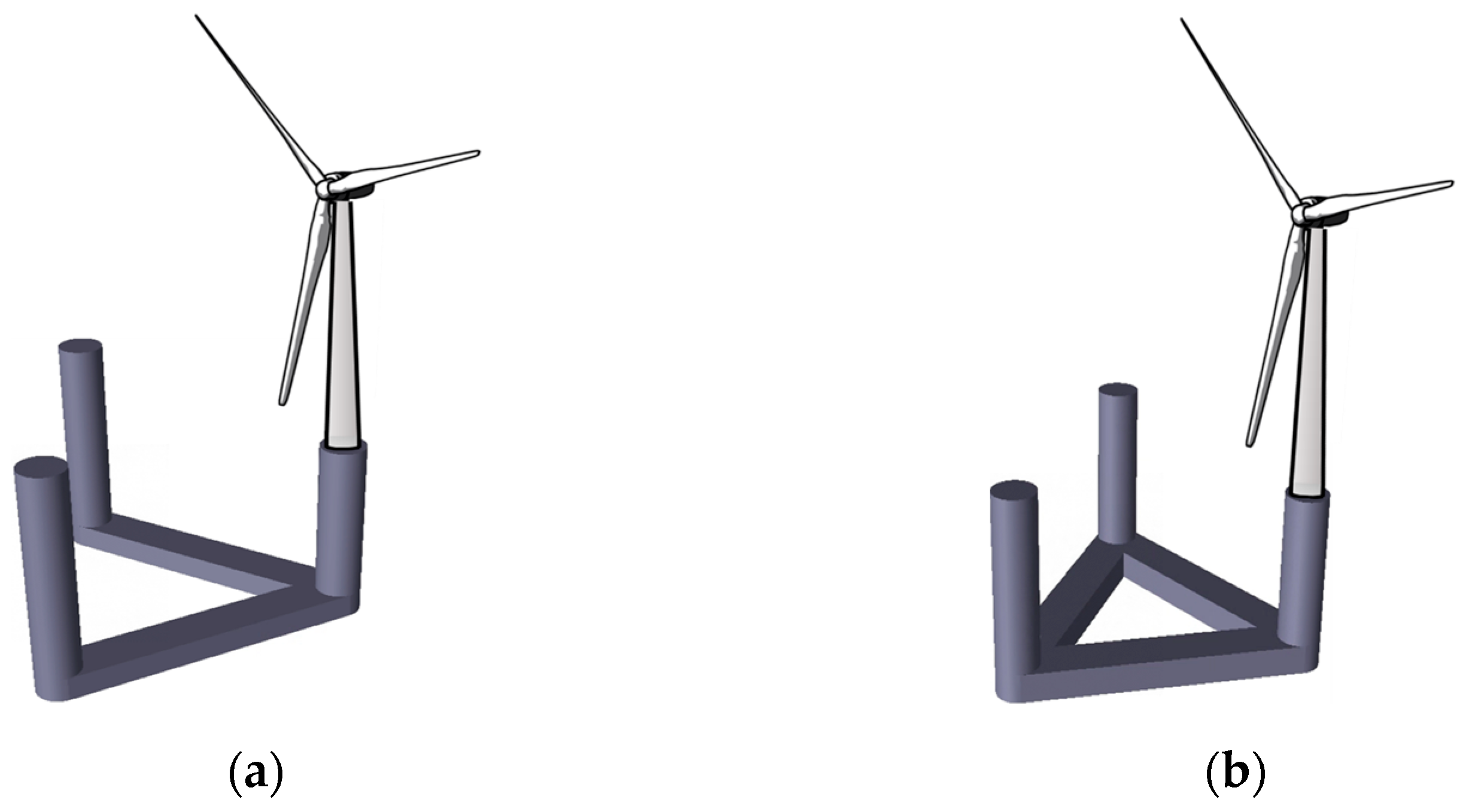
Figure 1.
Diagram of FOWT models: (a) V-shaped concept, (b) NewSemi concept.
2.4. Short-Term Response Prediction
Since the optimization process in this paper focuses on the hydrodynamic performance of the floater under extreme sea conditions, the nonlinear wind load acting on the wind turbine is ignored. Assuming the response of the floater is linear, the response spectrum under a stationary sea state is presented below [36]:
where is the floater motion response spectrum, is the response amplitude operator, and is the wave spectrum. The variance in the floater motion response can then be derived from the response spectrum.
3. Development of the NewSemi and Upscaled Concepts
3.1. Description of the NewSemi Floater for a 5 MW FOWT
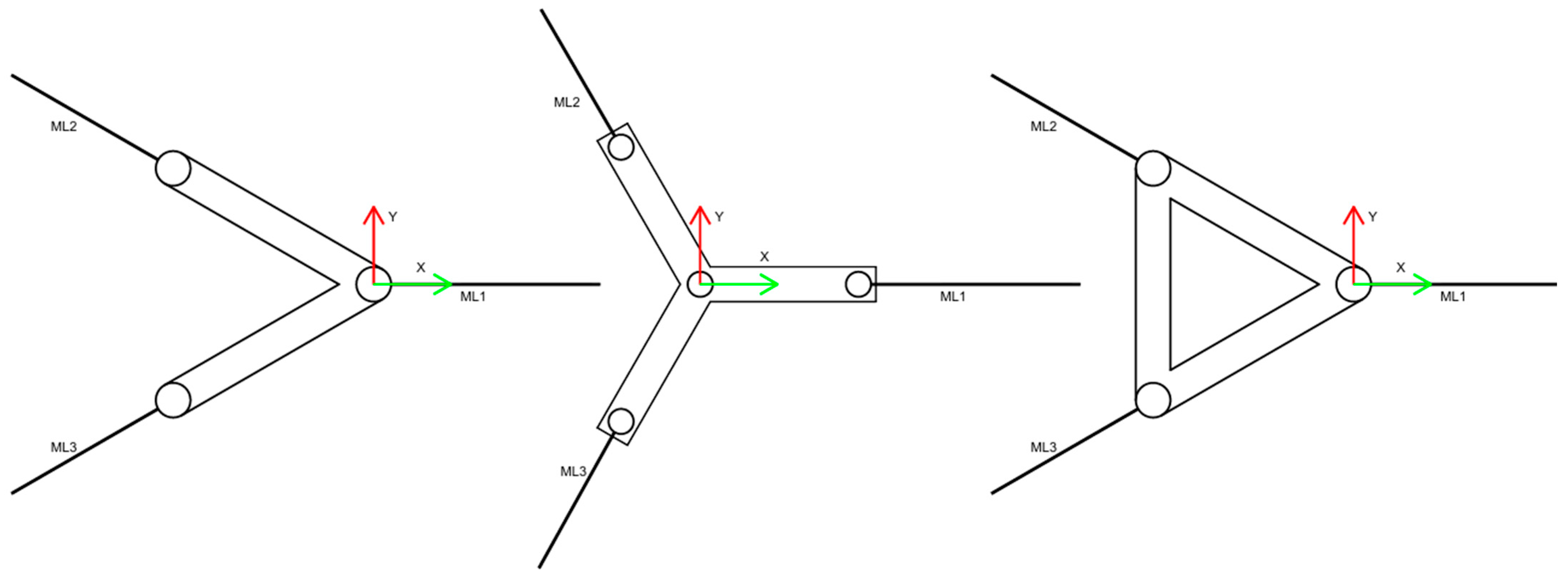
The NewSemi floater, an enhancement of the V-shaped concept, is a semi-submersible offshore wind turbine platform. It comprises three columns and two pontoons. The pontoons connect the side columns to the central column, forming a V-shaped structure. Some studies have shown that the natural frequency of the V-shaped floater in the pitch direction is too high, which interferes with the main wave energy zone under extreme sea conditions. This presents challenges for the floater’s application in the South China Sea, where typhoons are frequent and sea conditions are harsh. Recognizing the limitations of the V-shaped design, a new concept has been proposed. As shown in Figure 1, the novel NewSemi concept builds upon the V-shaped design by adding an additional pontoon, thereby improving the hydrodynamic performance of the floater. The parameters of the NewSemi platform, the V-shaped [16] and Braceless [12] reference platforms are shown in Table 1. The target water depth for the three floating wind turbine platforms is 95 m, and Table 2 provides mooring parameter information for the three platforms. It must be noted that the mooring layout and parameters of NewSemi and V-shaped are the same, while the mooring parameters of Braceless are different. The mooring parameter information of V-shaped and Braceless both refer to the research of Luan et al. [12] and Karimirad et al. [16]. We defined three mooring arrangements for the platform, as shown in Figure 2.

Table 1.
Detailed parameters of V-shaped, Braceless, and NewSemi platforms.
Table 2.
Detailed mooring system parameters of V-shaped, Braceless, NewSemi 5 MW and NewSemi 10 MW platforms.
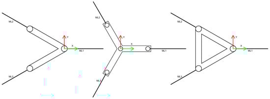
Figure 2.
The mooring arrangements of the three platforms mentioned.
3.2. Upscaling of the NewSemi Floater
Due to technological advancements and design changes, scaling FOWTs cannot rely solely on basic scaling ratios based on turbine ratings. Other factors must be considered during the upgrade process, including coupled dynamic motion, wave interaction, low-frequency response, and mooring systems [23].
Another purpose of this paper is to complete a semi-submersible floater suitable for a 10 MW wind turbine. The floater proposed earlier is only suitable for a 5 MW wind turbine. As the capacity of the wind turbine increases, the height and mass of its center of gravity also increase, which places higher demands on the stability of the floater. Therefore, the original dimensions are no longer applicable, which needs to be expanded. In this paper, column diameter (D1) and the distance between columns (D2) are selected as design variables. An optimization method is employed to carry out the upscaling design. The motion response of the floater under extreme sea conditions is taken as the optimization objective while adhering to constraints related to floater stability and steel consumption. The choice of extreme sea state is based on two considerations: First, when the wind turbine is operating, the presence of aerodynamic damping renders certain influence on the motion response of the floater by the hydrodynamic load [37]. Second, the target sea area for the floater is in the coastal region of Hainan, China, where typhoons are frequent and extreme sea states occur often [38].
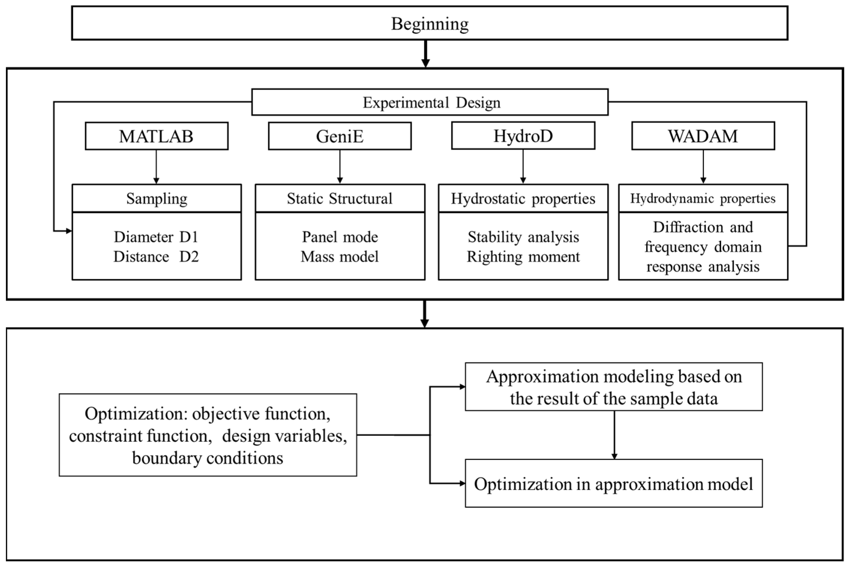
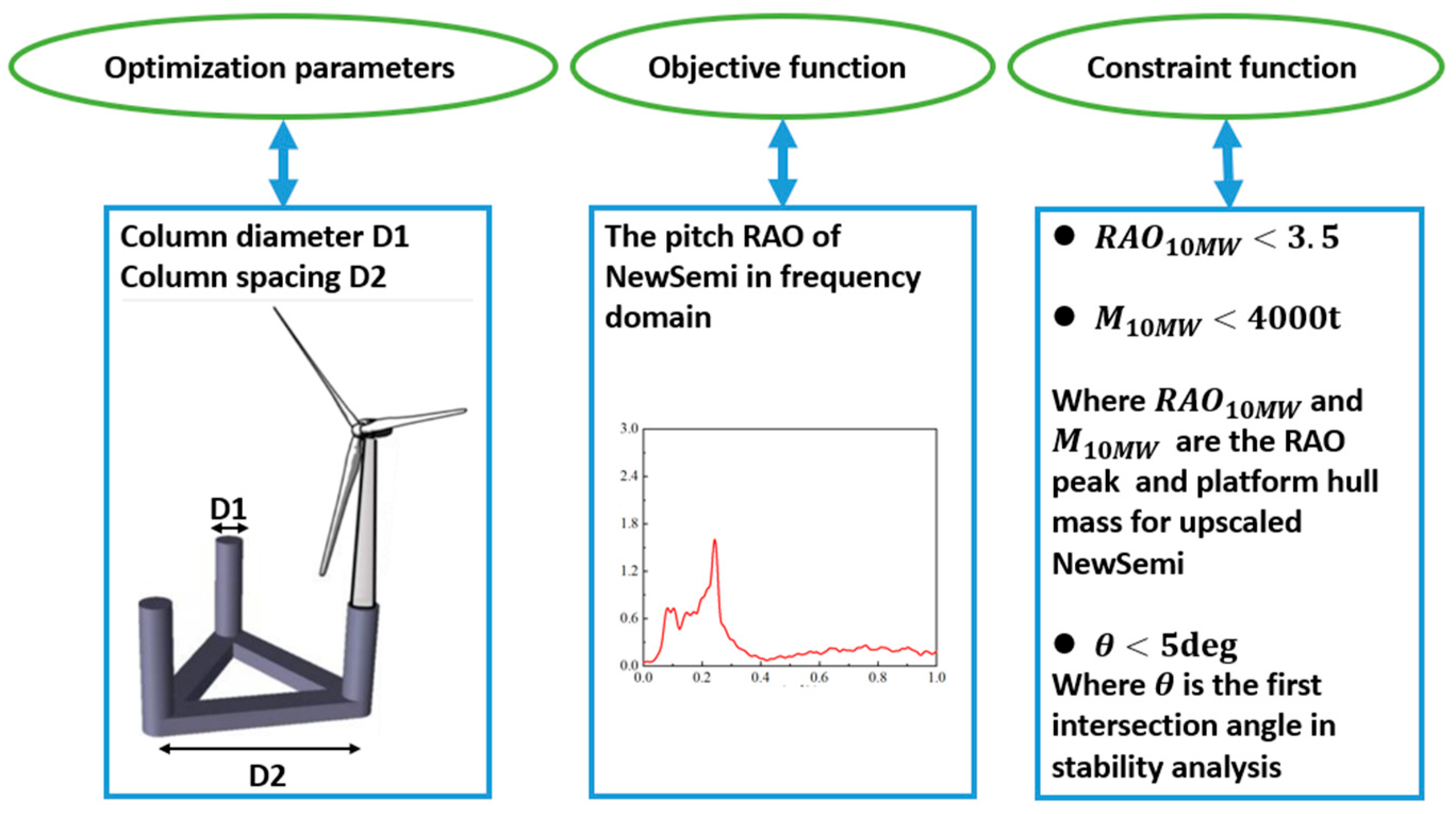
The upscaling optimization process is illustrated in Figure 3. The optimization parameter information is showed in Figure 4. This process can be divided into two parts: the sample preparation process and the optimization process. The optimal Latin-hypercube design method was used to select the diameter and distance of the floater as the test factors, as this method distributes all sample points uniformly in the design space, providing good space filling [39]. We set the lower limit of the column diameter D1 to 11 m and the upper limit to 14 m. The number of sampling points is 30 and the sequence is divided into equal parts; we set the lower limit of the column distance D2 to 70 m and the upper limit to 90 m. Similarly, the number and distribution of sampling points for D2 remain the same as D1. GeniE is used to model the floater and generate the panel and structural models after sampling, which is a widely used pre-processing software developed by Det Norske Veritas for the shipbuilding and marine engineering industry. Subsequently, the stability analysis of the floater is conducted in HydroD [40]. In this study, the righting moment at a heel angle of 5 degrees was selected as the stability function, as we want the first intersection angle of stability for the new floater to be of less than 5 degrees. The hydrodynamic analysis is carried out in WADAM, focusing on the significant values of pitch and heave response spectra of floater motion under extreme sea conditions. Due to the significant inhibitory effect of aerodynamic damping on heave, pitch, and nacelle motion of the semi-submersible floating wind turbine floater, the floater’s motion response under moderate sea conditions is primarily influenced by wind loads [41]. Therefore, the floater’s motion response under extreme sea conditions has been selected as the optimization variable.
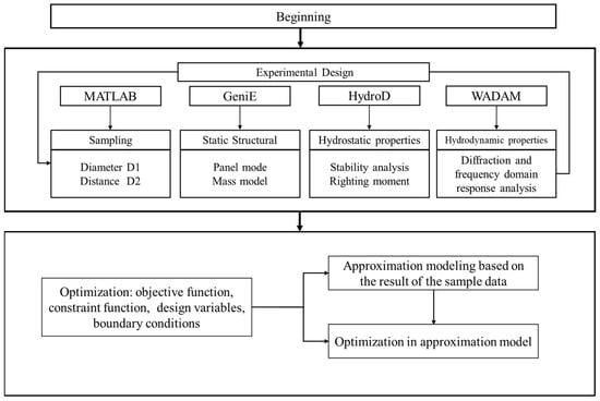
Figure 3.
Upscaling optimization process.
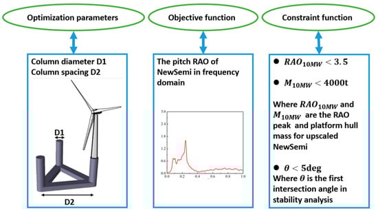
Figure 4.
Optimization parameter information for the upgraded version of NewSemi.
The approximation model simulates the relationship between a set of design variables and response variables. It analyzes the relationship between the inputs and outputs, helping to rapidly identify the optimal point. In this paper, the response surface model (RSM) was chosen to build the approximate model.
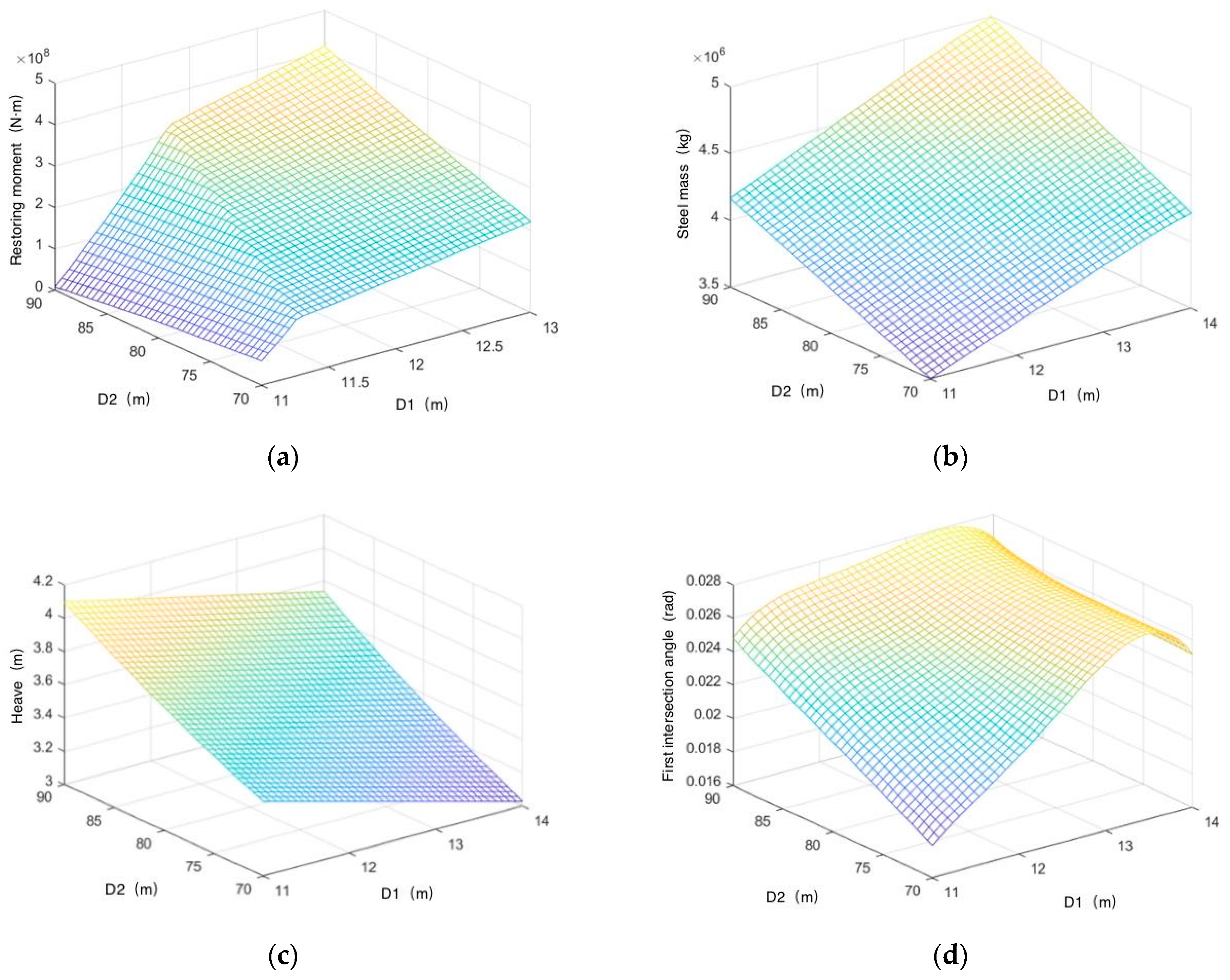
In the optimization, the column diameter D1 and distance D2 served as the optimization parameters. The optimization process utilized the differential evolution (DE) algorithm, with the objective function being the significant motion response in pitch direction of the floater under extreme sea conditions. In addition to the boundary conditions, there are three constraints: the significant heave response should be of less than 3.5 m, the steel mass of the platform hull should be of less than 4000 t, and the first intersection angle between the heeling moment curve and the righting moment curve should be of less than 5 degrees. Figure 5 shows the sensitivity analysis of the correlation between optimization factors and constraint conditions.
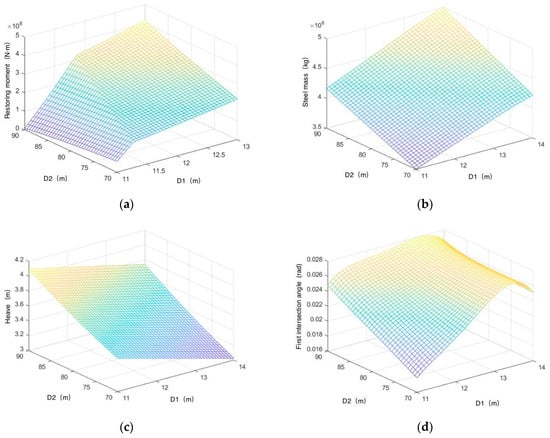
Figure 5.
Sensitivity analysis of the correlation between optimization factors and constraint conditions: (a) correlation analysis of restoring moment; (b) correlation analysis of steel mass; (c) correlation analysis of heave motion; (d) correlation analysis of first intersection angle.
The optimal parameters for the 10 MW floater were determined through the aforementioned optimization process. Finally, the column diameter was set to 12 m, and the distance between columns was set to 76.5 m.
3.3. Specifications of the 5 MW and 10 MW Wind Turbines
Both the V-shaped platform and the Braceless platform are equipped with the NREL 5 MW wind turbine proposed by the National Renewable Energy Laboratory (NREL) in the United States [11,16]. The NewSemi 5 MW platform designed in this study also focuses on the NREL 5 MW wind turbine for research purposes. The upscaled NewSemi 10 MW platform is equipped with the DTU 10 MW wind turbine, jointly developed by the Wind Energy Department of the Technical University of Denmark and Vestas [42]. The main design parameters of the turbines are shown in Table 3. The cut-in wind speed, rated wind speed, and cut-out wind speed are the same for both turbines, achieving good compatibility in the design environmental conditions. The specific parameters of the two types of wind turbine towers are shown in Table 4.
Table 3.
Specifications of the 5 MW and 10 MW wind turbines.
Table 4.
Characteristics of the tower of the 5 MW and 10 MW wind turbines.
3.4. Comparison of the Motion Natural Periods of the Four FOWT Concepts
With no environmental loads (e.g., wind, waves, currents), an initial displacement was applied to the wind turbine floater, followed by a free decay simulation test in SIMA. The decay test time history was recorded, and natural periods of the four FOWTs were obtained via numerical time-series Fourier transform (Table 5). Notably, the V-shaped floater has a much higher pitch direction natural period than the others, suggesting potential difficulty in aligning with the main wave energy zone under extreme sea conditions.
Table 5.
Natural periods of the floater motions of wind turbines.
The magnitude of damping has a significant impact on the decay speed and amplitude of free decay testing. In this section, a damping analysis for decay testing was conducted to demonstrate the order of magnitude differences between radiation damping and viscous damping for four different platforms. As shown in Table 6, viscous damping plays a major role in the motion of the FOWT system.
Table 6.
Comparison of damping between different wind turbine platforms.
4. Comparative Analysis of the Dynamic Characteristics of the 5 MW FOWTs
In this chapter, the dynamic characteristics of the V-shaped, NewSemi, and Braceless platforms are compared using SIMA software. We provide evidence from the frequency- and time-domain perspectives, demonstrating the NewSemi platform’s better hydrodynamic performance in terms of RAO, radiation damping, motion response, and structural dynamic response. Due to the fact that this article is based on the theory of potential flow, in order to compensate for the insufficient estimation of fluid viscosity effects, the viscous load effect experienced by the floaters is simulated by setting a critical damping of 3% in the pitch, roll, and heave directions during hydrodynamic parameters calculation. In the subsequent time-domain analysis section, the Morison virtual element will be added to correct the quadratic drag force coefficient, which is calculated based on relevant DNV specifications.
4.1. Environmental Conditions
This chapter selects several representative load cases (LCs) to investigate the dynamic response of 5 MW FOWTs on three different semi-submersible floaters, as shown in Table 7. These load cases cover constant and turbulent wind conditions, as well as scenarios of rated, above-rated, cut-out, and parked conditions. They will also illustrate the dynamic response comparisons between the NewSemi 5 MW and 10 MW FOWTs. In load cases LC4 to LC7, a turbulent wind field over a 180 × 180 m vertical plane centered on the rotor was generated in TurbSim using IEC Kaimal spectra based on normal turbulence model (NTM) conditions and turbulence category A. The JONSWAP spectrum was used to generate the irregular wave time series.
Table 7.
Definition of load cases.
4.2. Comparative Analysis of the Response Amplitude Operator (RAO) for the 5 MW FOWTs
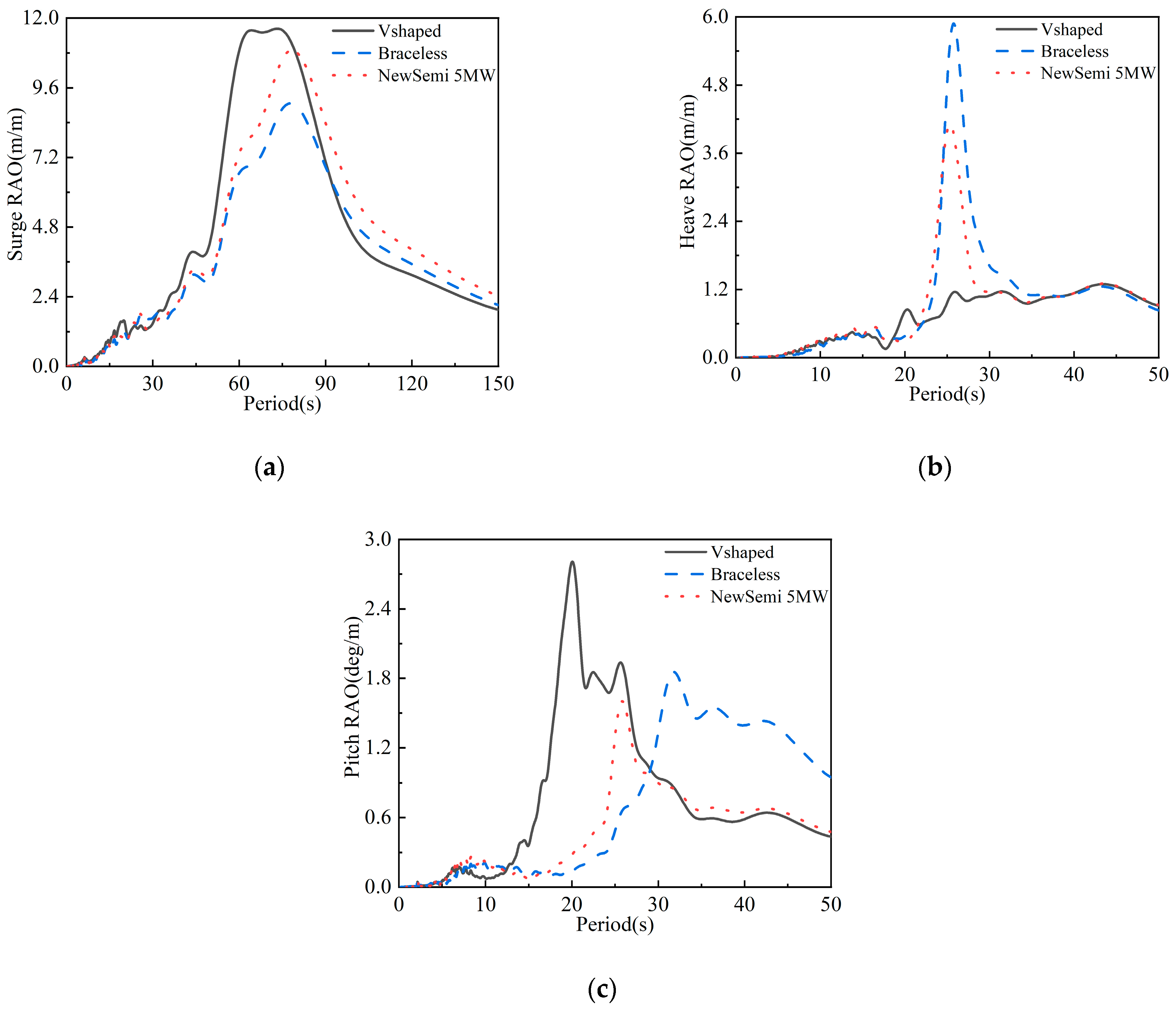
The main scale design of FOWT has a significant impact on its hydrodynamic parameters, and the response amplitude operator (RAO) is one of the important indicators. In this section, we compared and analyzed the improved NewSemi configuration with existing publicly available V-shaped and unsupported models based on the same 95 m water depth to demonstrate the RAO differences between the three platform configurations. It quantifies the floater’s motion response to regular wave excitations across different frequencies. The RAO reveals the floater’s motion characteristics under specific conditions, considering first-order wave forces, added mass, and radiation damping effects. The floater’s natural motion periods for each degree of freedom can be derived from the RAOs. Figure 6 presents the RAOs of the three 5 MW FOWTs in the heave, surge, and pitch directions.
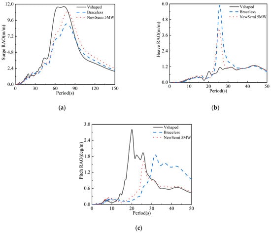
Figure 6.
Comparison of the motion RAOs of the three 5 MW FOWTs: (a) surge RAO; (b) heave RAO; (c) pitch RAO.
Figure 6a shows that in the surge direction, all three FOWTs have two peaks in their RAO curves. These correspond to the natural periods of surge and pitch motions, indicating coupling between them. The first peak, which is much higher than the second, represents the natural frequency of surge motion. The peak values at this point decrease in the order of V-shaped, NewSemi, and Braceless FOWTs.
For single-degree-of-freedom resonant load response, the steady-state response at the natural period depends on the static displacement and dynamic amplification factor. The static displacement is influenced by the first-order wave force and restoring stiffness, while the dynamic amplification factor is determined by the damping. At low frequencies, the floater’s potential flow damping is nearly zero, and the numerical model’s damping mainly comes from the Morrison equation’s quadratic damping term, an empirical calculation method. However, wave-induced low-frequency excitation is minimal and does not cause resonance. The floater’s motion response under isolated wave action remains quasi-static, with response energy concentrated at the wave peak frequency. Within the main wave frequency range (3–20 s), the three FOWTs’ comparison shows that, compared to the V-shaped FOWT, the NewSemi FOWT has a significant advantage in this frequency range, similar to the Braceless FOWT.
The FOWT’s heave-direction motion response is less influenced by wind loads and is mainly controlled by wave frequencies, exhibiting quasi-static characteristics. Figure 6b’s comparison indicates that within the wave frequency range, the V-shaped FOWT has the best heave performance, the Braceless FOWT has the poorest, and the NewSemi FOWT is in between. All three FOWTs show a peak frequency of approximately 0.4 rad/s, consistent with the FOWT’s heave direction natural frequency.
From Figure 6c, it can be observed that all three FOWTs exhibit three peaks in the pitch motion response RAO, corresponding to the natural periods of pitch motion, surge motion, and the peak frequency of the wave excitation force. Additionally, the pitch RAO for the NewSemi FOWT is noticeably better, with the lowest peak compared to the V-shaped and Braceless FOWTs. Furthermore, the NewSemi FOWT effectively addressed the issue of interacting with the main wave energy zone under extreme sea conditions, which is a challenge for the V-shape FOWT.
Comparing the motion RAOs of the three FOWTs, the V-shaped FOWT has the poorest surge motion, while the Braceless FOWT performs worst in heave motion. The NewSemi FOWT shows an intermediate response in both directions and does not exhibit extreme responses in any particular motion. This optimization mainly focused on pitch motion, and the NewSemi FOWT performs best in this regard. It reduces peak RAO values and improves the FOWT’s natural period, minimizing the risk of resonance with the main wave energy zone under extreme sea conditions.
4.3. Comparative Analysis of the Radiation Damping for the 5 MW FOWTs
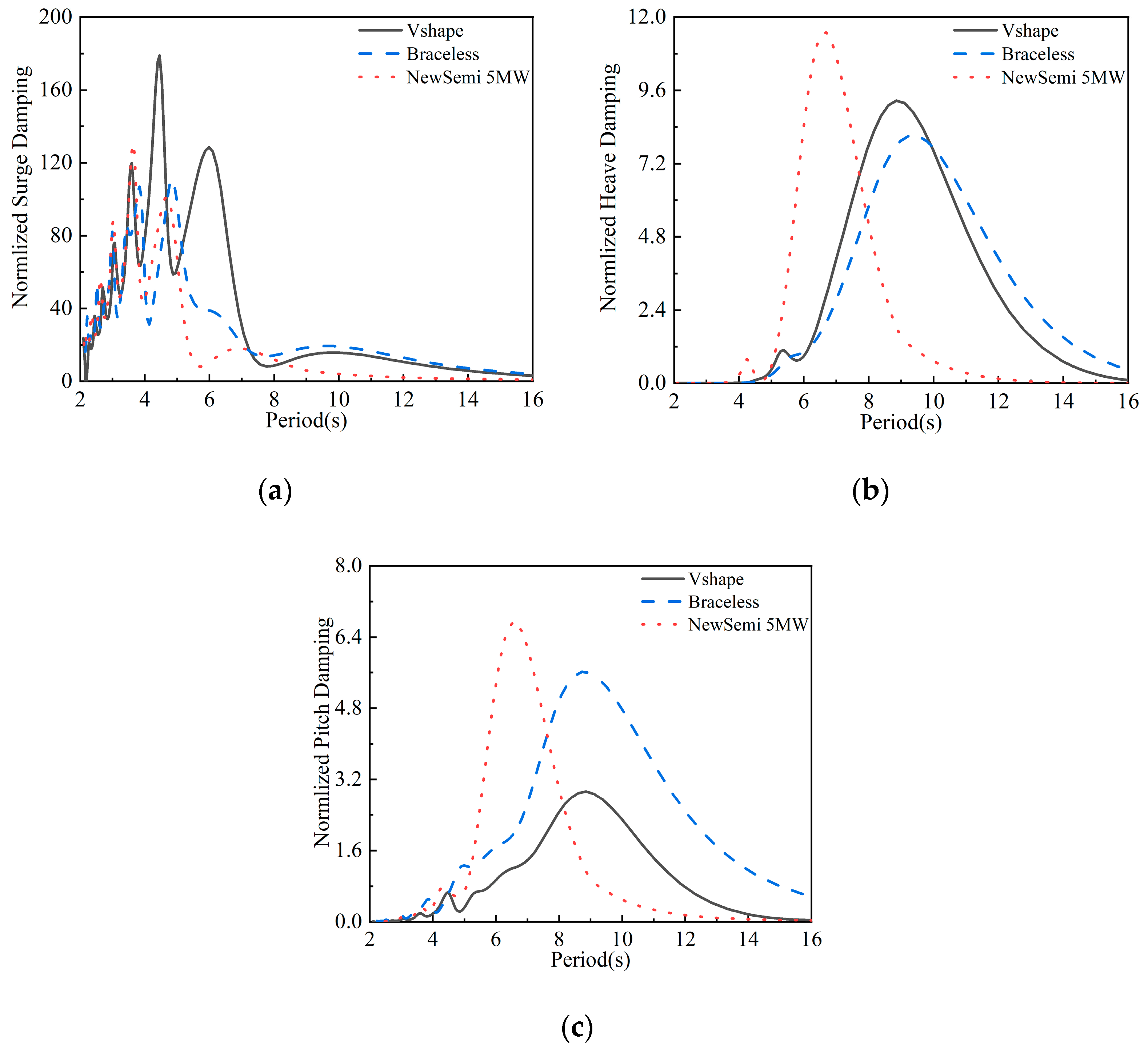
Figure 7 represents the dimensionless radiation damping coefficient, which is obtained by considering critical damping without including additional mass in each FOWT. It can be observed that the surge direction has a larger radiation damping coefficient, reaching approximately twice the critical damping. When comparing the three FOWTs for a 5 MW turbine, multiple peaks can be seen within the wave frequency range. Overall, the radiation damping coefficients decrease as the wave frequency increases.
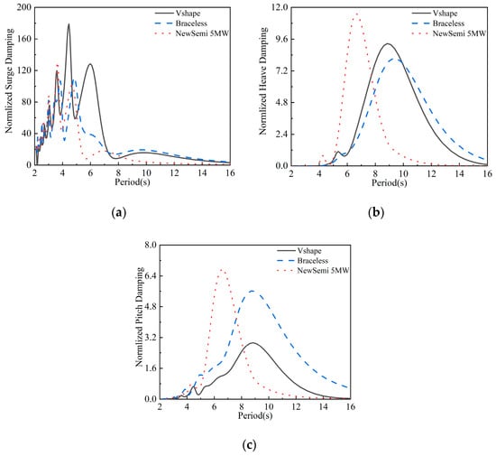
Figure 7.
Comparison of the radiation damping of the three FOWTs: (a) normalized surge damping; (b) normalized heave damping; (c) normalized pitch damping.
In the heave direction, all FOWTs exhibit two peaks. Among them, the NewSemi FOWT demonstrates excellent damping characteristics, providing the highest radiation damping with controllable distribution. Our optimization goal was to minimize the pitch response of the FOWT under extreme sea conditions. The optimization results show that the peak of radiation damping in the pitch direction shifts to the left, which suppresses the response to low-frequency wave loads and reduces the pitch response of the FOWT under these conditions. Similar results are observed in the heave direction, influenced by the coupled characteristics between the heave and pitch responses.
4.4. Comparative Analysis of the Motion Responses for the 5 MW FOWTs
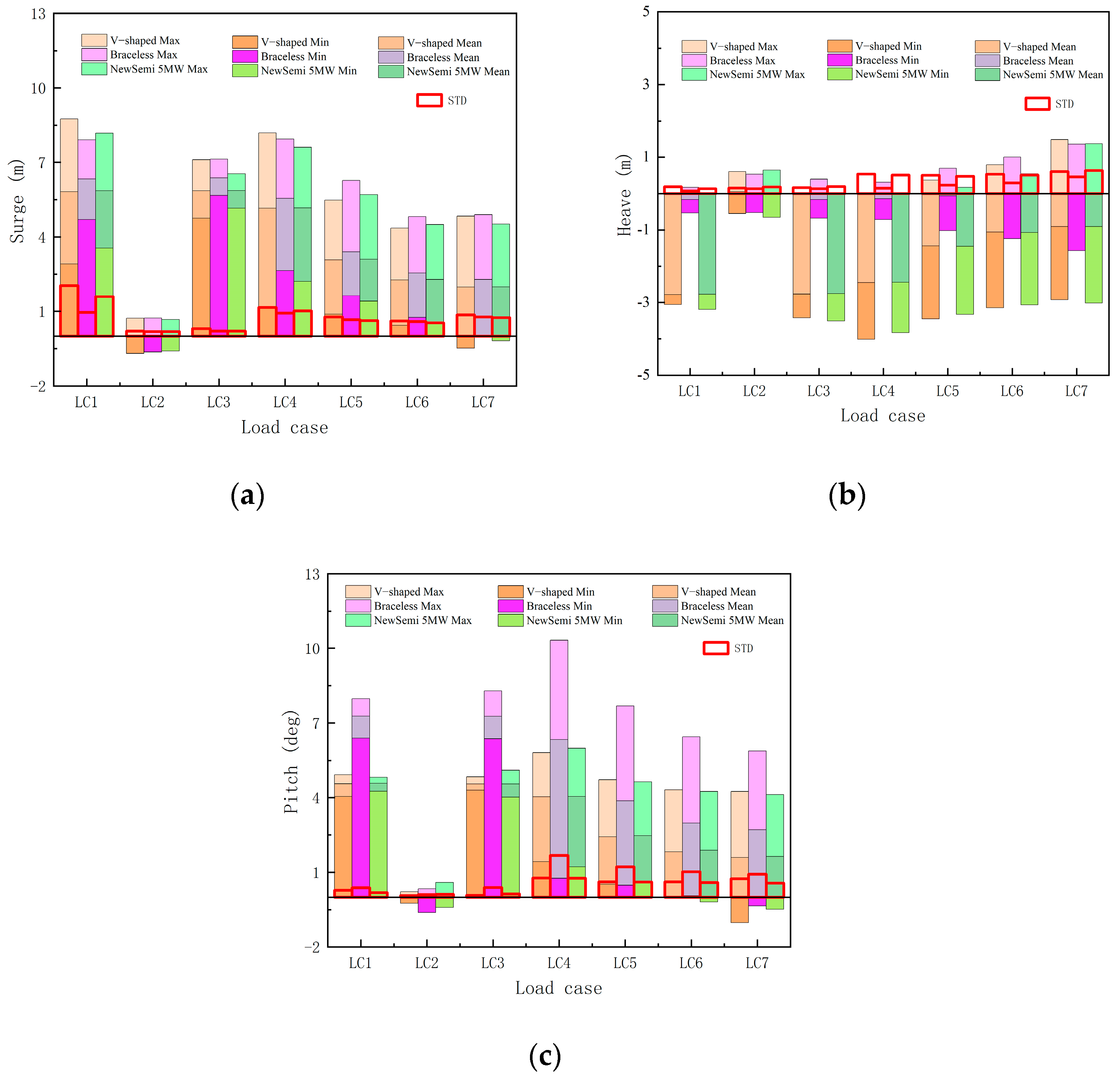
The motion statistics in the time domain provide a more direct demonstration on the hydrodynamic performance under real ocean conditions. Figure 8 presents the statistical results of the motion responses for the three FOWTs under specified environmental conditions. Figure 9 shows the statistical results of the nacelle acceleration of three FOWTs. The average motion values in the surge and pitch directions are similar for the V-shaped and NewSemi FOWTs, with both being smaller than those of the Braceless FOWT. Under extreme environmental condition (LC7), the average motion response of the NewSemi FOWT in these two directions is reduced by 14.6% and 65.2%, respectively. In terms of nacelle acceleration in the surge direction, the NewSemi’s results under the influence of high wind speed sea state LC5 decreased by 16% compared to V-shaped’s results, while the NewSemi’s results under extreme sea state LC7 were only 54.6% of V-shaped’s results. In the pitch direction, the acceleration also decreased variously in extreme conditions. Additionally, the standard deviation (STD) of the NewSemi FOWT for each operating condition is smaller than that of the V-shaped FOWT. Under extreme environmental conditions (LC7), the STD of the NewSemi FOWT is reduced by 11.3% and 31.9%, respectively. This demonstrates that the NewSemi FOWT exhibits good stability in the surge and pitch directions, maintaining balance in various environments. However, in the heave direction, the Braceless FOWT has better mean and standard deviation values compared to the other two FOWTs. The smaller surge response can effectively reduce the possibility of fatigue failure caused by excessive longitudinal motion, and the optimization in the pitch direction meets the goal of this study.
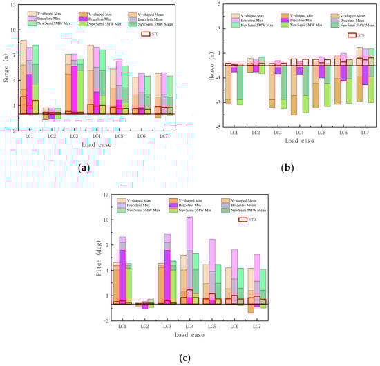
Figure 8.
Statistical results of the motion response of three FOWTs under different cases: (a) surge motion; (b) heave motion; (c) pitch motion.
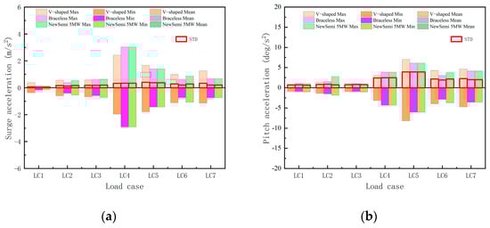
Figure 9.
Statistical results of the nacelle acceleration of three FOWTs under different cases: (a) surge; (b) pitch.
5. Comparisons of the Dynamic Characteristics Between the Upscaled NewSemi 10 MW and 5 MW FOWTs
In this section, a frequency domain comparative analysis was conducted between the upscaled NewSemi 10 MW and 5 MW FOWTs, including the response amplitude operator and radiation damping. Additionally, fully coupled numerical models for the 10 MW and 5 MW FOWTs were established using DNV SIMA software, serving as the basis for a comparative study on the motion response and structural dynamic response of the floating wind turbines under combined wind and wave effects.
5.1. Comparisons of the RAOs for the 10 MW and 5 MW FOWTs
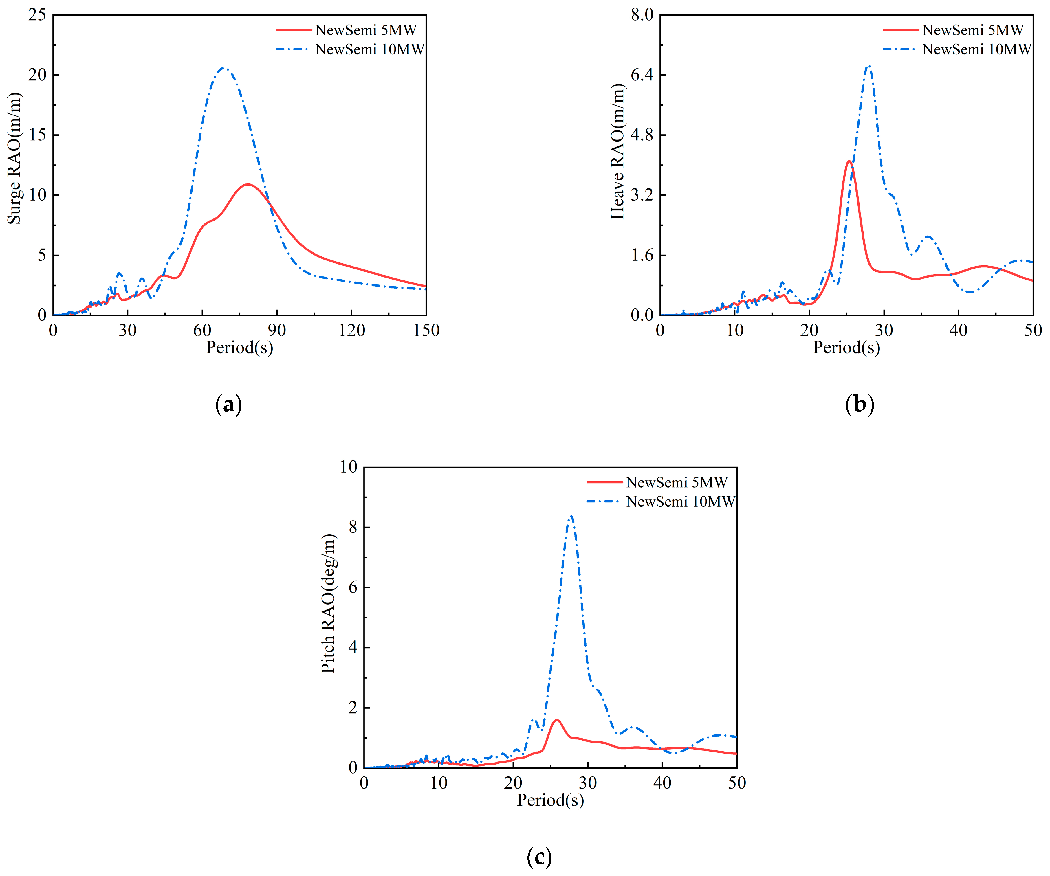
Figure 10 compares the RAO of the NewSemi 10 MW and 5 MW FOWTs in the surge, heave, and pitch directions under zero wind speed. The results show that scaling up the platform for a higher-power turbine does not significantly change the peak frequency of the RAO in each direction. The maximum peak frequencies align with the FOWTs’ natural frequencies in those directions.
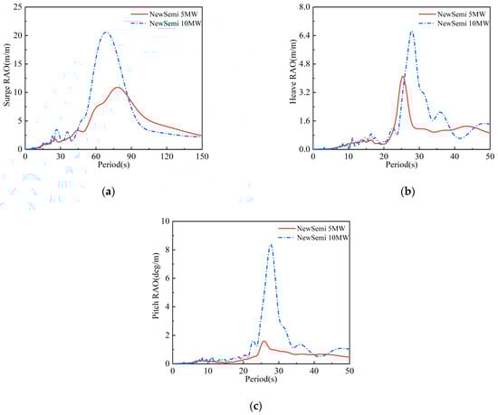
Figure 10.
Comparison of the motion RAOs of the 10 MW and 5 MW FOWT: (a) surge RAO; (b) heave RAO; (c) pitch RAO.
However, the maximum peak values for the 10 MW FOWT increase by 46.58%, 37.94%, and 80.22% in the surge, heave, and pitch directions, respectively, with the pitch direction seeing the largest rise. This is because scaling up the floater greatly increases the mass of the carried DTU 10 MW turbine compared to the NREL 5 MW turbine. Moreover, the larger floater size boosts the distance between the turbine and the axis of rotation, significantly increasing the FOWT’s moment of inertia about the Y-axis and thus the peak RAO in the pitch direction.
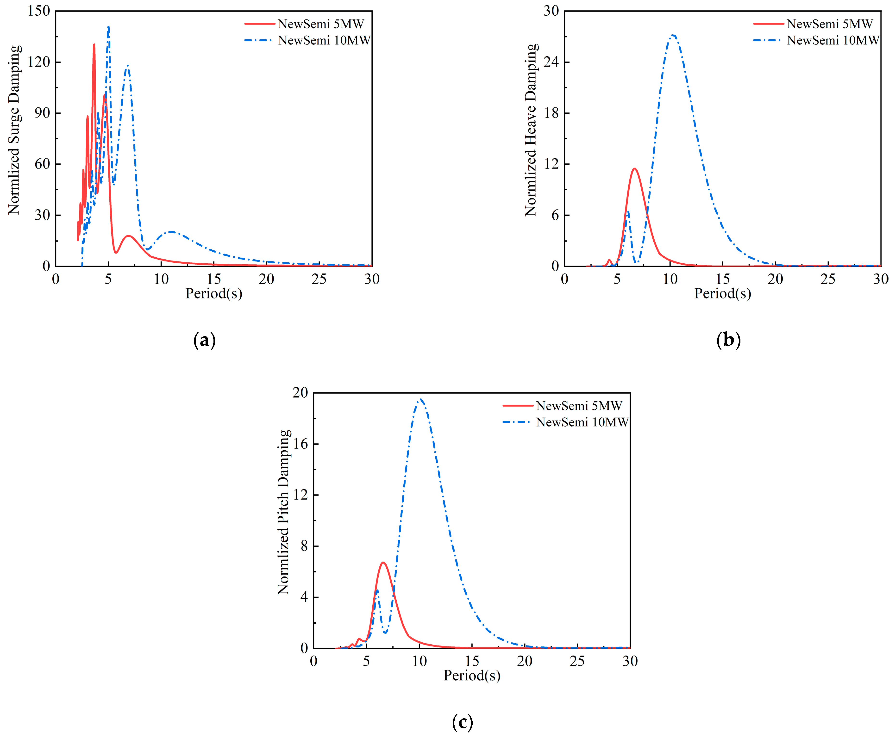
5.2. Comparisons of the Radiation Damping for the 10 MW and 5 MW FOWTs
Figure 11 compares the dimensionless radiation damping coefficients of the NewSemi 10 MW and 5 MW FOWTs. In the surge direction, both FOWTs show similar peak heights and trends, but the 10 MW FOWT has a lower peak frequency. In the pitch direction, both have two peaks. After scaling up to 10 MW, the NewSemi FOWT retains its good damping characteristics, with the maximum radiation damping ratio rising by 187.85% compared to the 5 MW FOWT. This improvement reduces the FOWT’s pitch response in extreme sea conditions. Similar results are seen in the pitch direction, influenced by the coupled heave and pitch response characteristics.
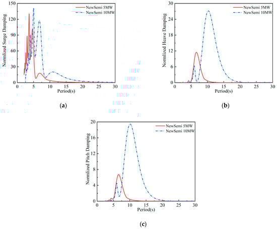
Figure 11.
Comparison of the radiation damping of the two FOWTs: (a) normalized surge damping; (b) normalized heave damping; (c) normalized pitch damping.
5.3. Comparisons of the Motion Response for the 10 MW and 5 MW FOWTs
Table 8 presents the simulation results for the motion response of the NewSemi 10 MW FOWT compared to the NewSemi 5 MW FOWT (Figure 8). For rated wind speed, cut-out wind speed, and extreme wind speed conditions, the average values of the NewSemi 10 MW FOWT in the surge direction decreased by 11.8%, 64.9%, and 58.3%, respectively, compared to the 5 MW FOWT. This indicates that the NewSemi 10 MW FOWT, optimized using the optimal Latin-hypercube design method, exhibits excellent motion response. Figure 12 shows a comparison of the motion response between the NewSemi 10 MW and 5 MW FOWTs in the heave and pitch directions for the LC6 and LC7 cases. It is evident that the amplitude and displacement from the equilibrium point of the NewSemi 10 MW FOWT in the heave and pitch directions are significantly smaller than those of the 5 MW FOWT. This can be attributed to the larger structural weight and buoyancy of the 10 MW floater, which provide strong restoring forces and moments for heave and pitch motion.
Table 8.
Statistical results of the motion response for the 10 MW NewSemi.
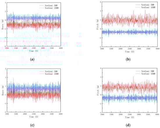
Figure 12.
Comparison of time-domain motion response of FOWTs: (a) heave motion for the LC6 case; (b) pitch motion for the LC6 case; (c) heave motion for the LC7 case; (d) pitch motion for the LC7 case.
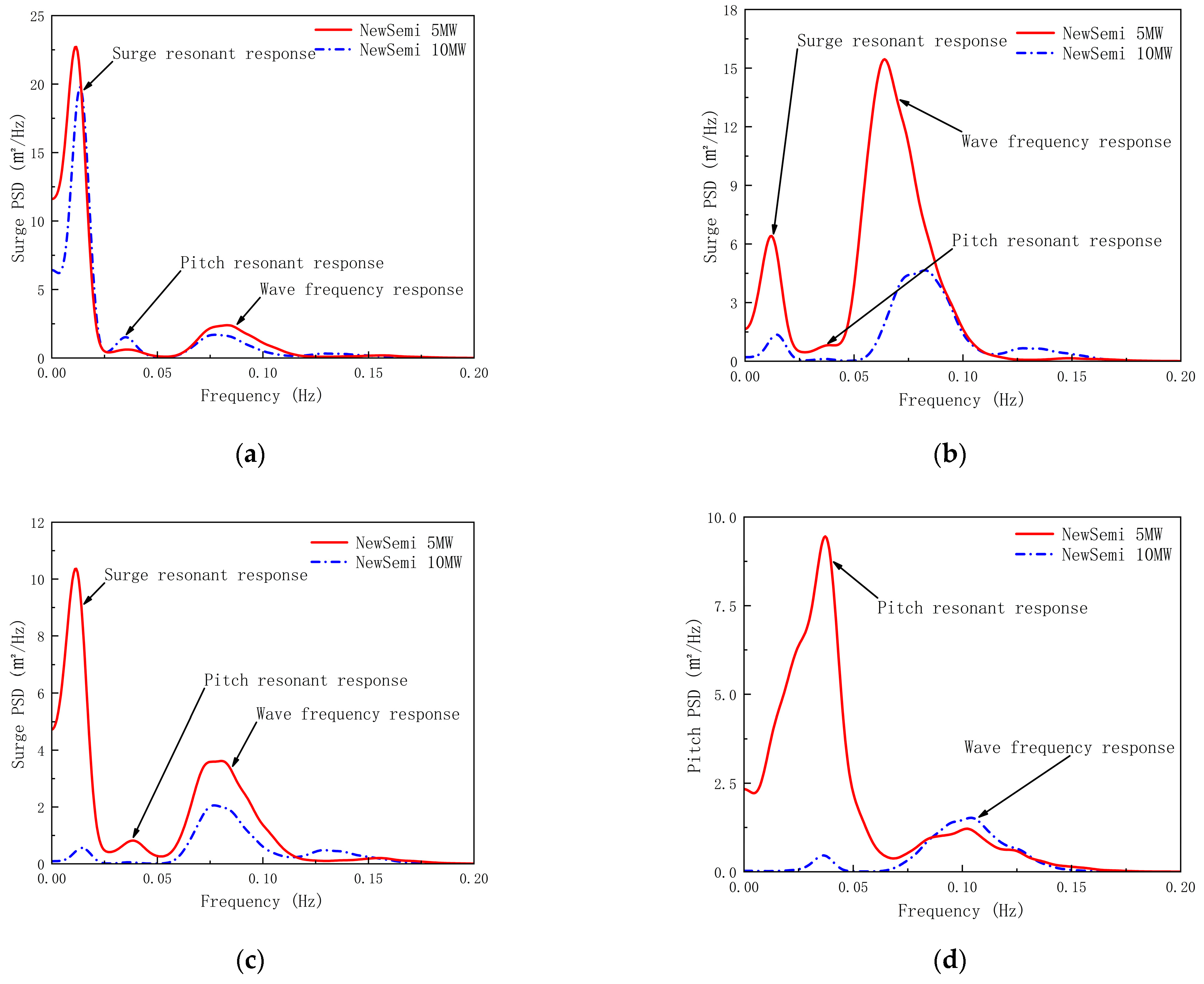
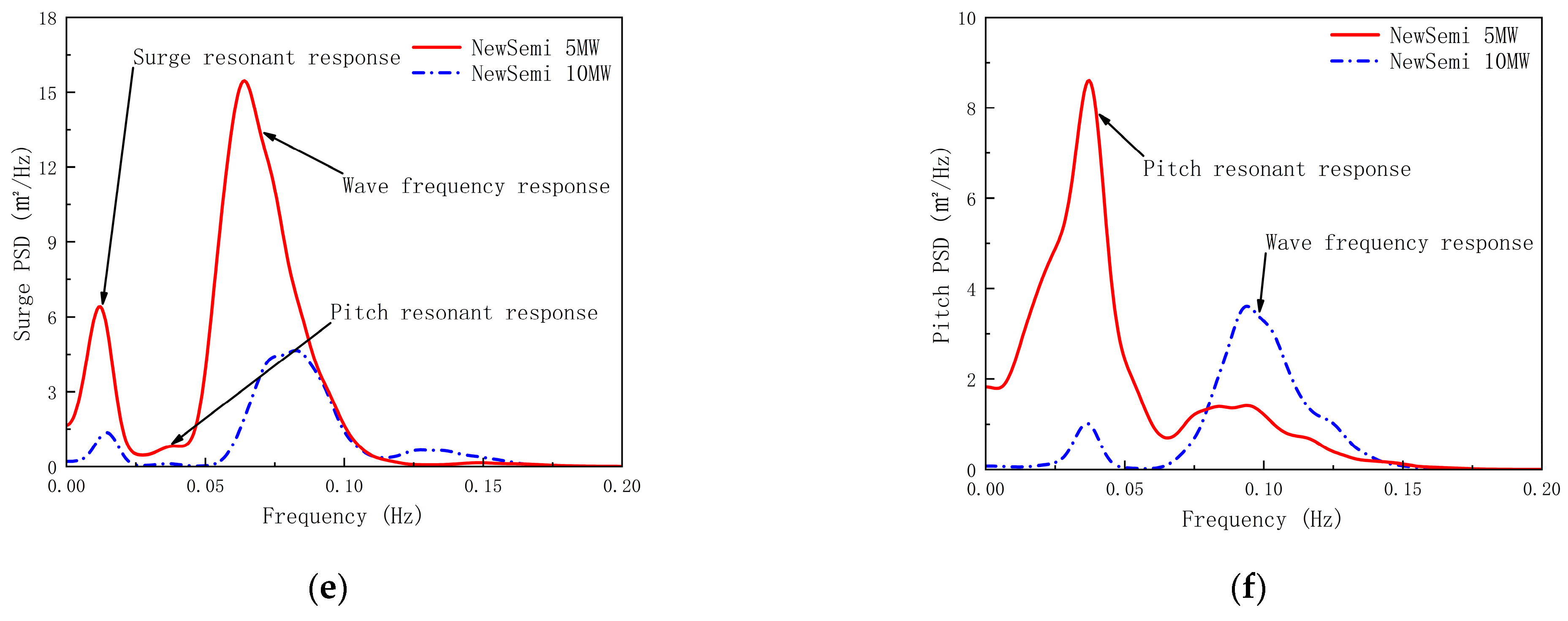
Figure 13 compares the surge and pitch motion response power spectra of the NewSemi 10 MW and 5 MW FOWTs for the LC5 to LC7 cases. Under the rated wind speed condition (LC5), the amplitudes of the surge and pitch resonant responses of the FOWTs, excited by low-frequency wind loads and wave-frequency responses from wave loads, are nearly identical. However, in the pitch direction, the resonant response of the 10 MW turbine, caused by low-frequency wind loads, is significantly higher.
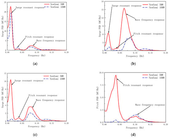
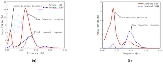
Figure 13.
Comparison of power spectra of floater motion responses: (a) power spectra of surge motion for the LC5 case; (b) power spectra of pitch motion for the LC5 case; (c) power spectra of surge motion for the LC6 case; (d) power spectra of pitch motion for the LC6 case; (e) power spectra of surge motion for the LC7 case; (f) power spectra of pitch motion for the LC7 case.
Under extreme conditions (LC6 and LC7), the FOWTs employ variable pitch control to achieve feathering, effectively reducing the excitation of low-frequency wind loads on floater motion. As a result, the amplitude of the surge and pitch resonant response of the 10 MW FOWT is significantly smaller. However, there is a difference in the wave frequency response between the two motion directions. In the surge direction, the amplitude of the 10 MW FOWT is smaller, while in the pitch direction, it is larger. Therefore, we can predict that under extreme conditions (when the FOWTs are in a feathered state), as the size of the FOWTs increases, the excitation of low-frequency wind loads on the FOWT motion response will decrease.
5.4. Comparison of the Structural Dynamics for the 10 MW and 5 MW FOWTs
According to Table 9, a comparison was made of the structural dynamics, including root torque, rotor thrust, tower-base-bending moment and axial force (TwrbsMyt and TwrbsAxf), as well as the mooring line tensions in the leeward and windward directions (ML1 tension and ML2 tension), between the 10 MW and 5 MW FOWTs under the LC5, LC6, and LC7 cases. This article selected the connection between the root of the blade and the hub for the determination of Root Torque and defined Thrust as the amount of thrust received by the Hub along the Surge direction, TwrbsMyt as the moment of the tower base around the Y-axis direction (perpendicular to the wind direction) and TwrbsAxf as the axial force value along the tower height direction at the tower base.
Table 9.
Response statistics of structural loads of the 10 and 5 MW FOWT.
Regardless of whether operating normally or in a feathered state, the structural dynamic response of the 10 MW FOWT exceeds that of the 5 MW FOWT, with more significant fluctuations in structural load. Under the three selected operating conditions, the root torque of the 10 MW FOWT can reach more than three times that of the 5 MW FOWT, while the tower base axial force can reach twice as much. However, the rotor thrust is only about 1.5 times greater. Under rated wind speed conditions, the tower-base-bending moment of the 10 MW FOWT is twice that of the 5 MW FOWT. In contrast, in extreme conditions, the tower-base-bending moment can reach up to 16 times (LC6) and 5.6 times (LC7) that of the 5 MW FOWT.
The axial tension response of the mooring lines on the FOWTs exhibits different characteristics. The mooring line tensions for both the 10 MW and 5 MW FOWTs are nearly identical, and in most cases, the tension fluctuations in the 10 MW FOWT are smaller than those in the 5 MW FOWT. The statistical data provide valuable references for the design, application, and reliability analysis of large-scale FOWTs in the future.
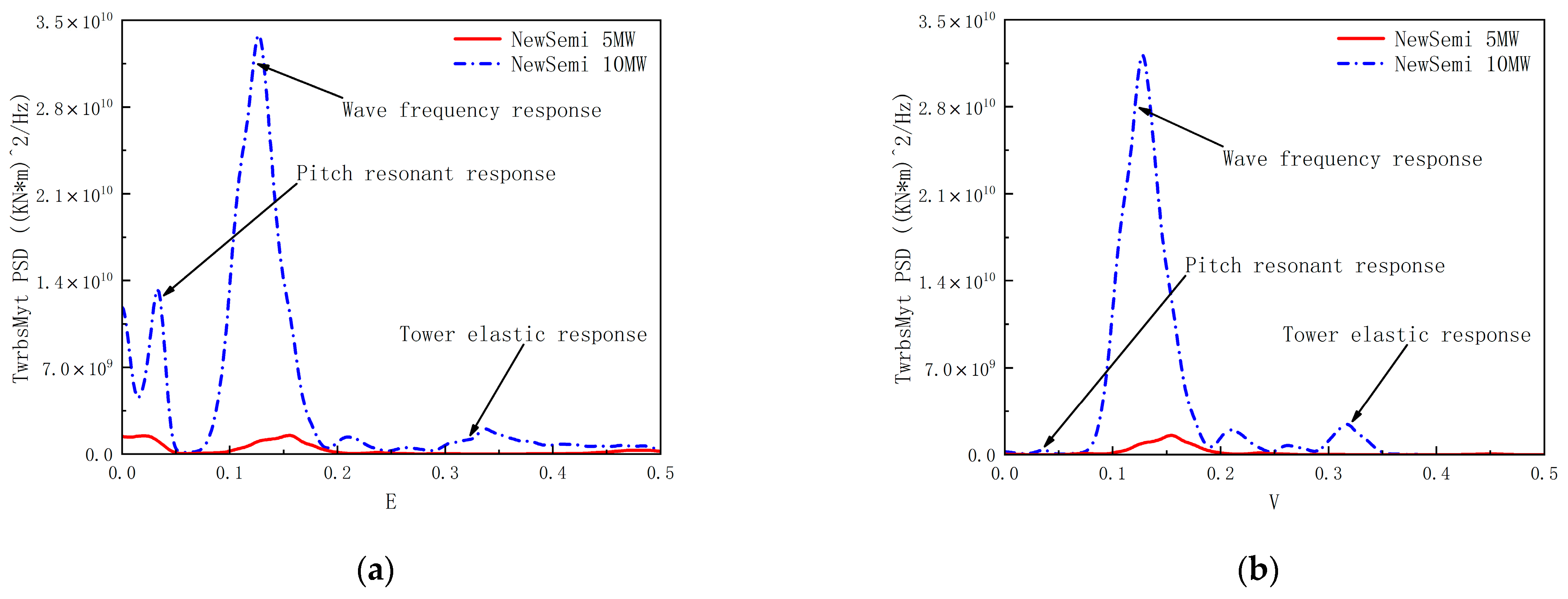
As shown in Figure 14, the power spectral analysis of the tower-base-bending moment response for 10 MW and 5 MW FOWTs was conducted under the LC5, LC6, and LC7 cases. The results indicate that the tower-base-bending moment for both the 5 MW and 10 MW FOWTs is primarily controlled by wave loads. The 10 MW FOWT exhibits a significantly higher amplitude of tower-base-bending moment response due to the excitation from wave loads. Additionally, the low-frequency wind loads and the elastic response of the tower structure have a more pronounced excitation effect on the structural dynamic response of the 10 MW FOWT, especially in extreme sea conditions. Notably, in the low-frequency range, the peak response of the tower-base-bending moment corresponds to the natural period of the FOWTs in the pitch direction, indicating a relationship between the magnitude of the bending moment at the FOWTs’ tower base and the floater’s motion in the pitch direction.
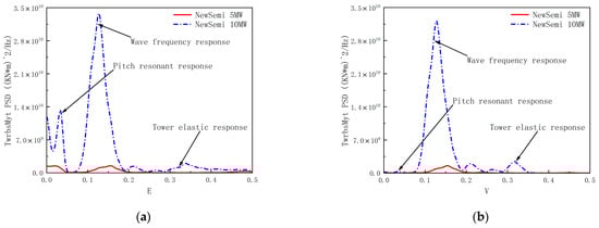
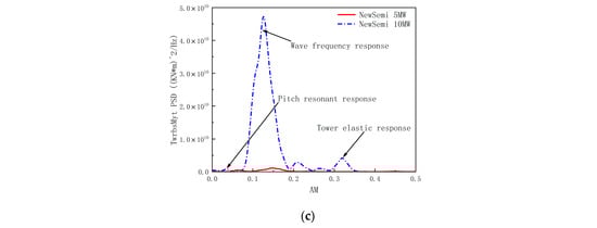
Figure 14.
Comparison of the power spectra of TwrbsMyt response: (a) power spectra of TwrbsMyt response for the LC5 case; (b) power spectra of TwrbsMyt response for the LC6 case; (c) power spectra of TwrbsMyt response for the LC7 case.
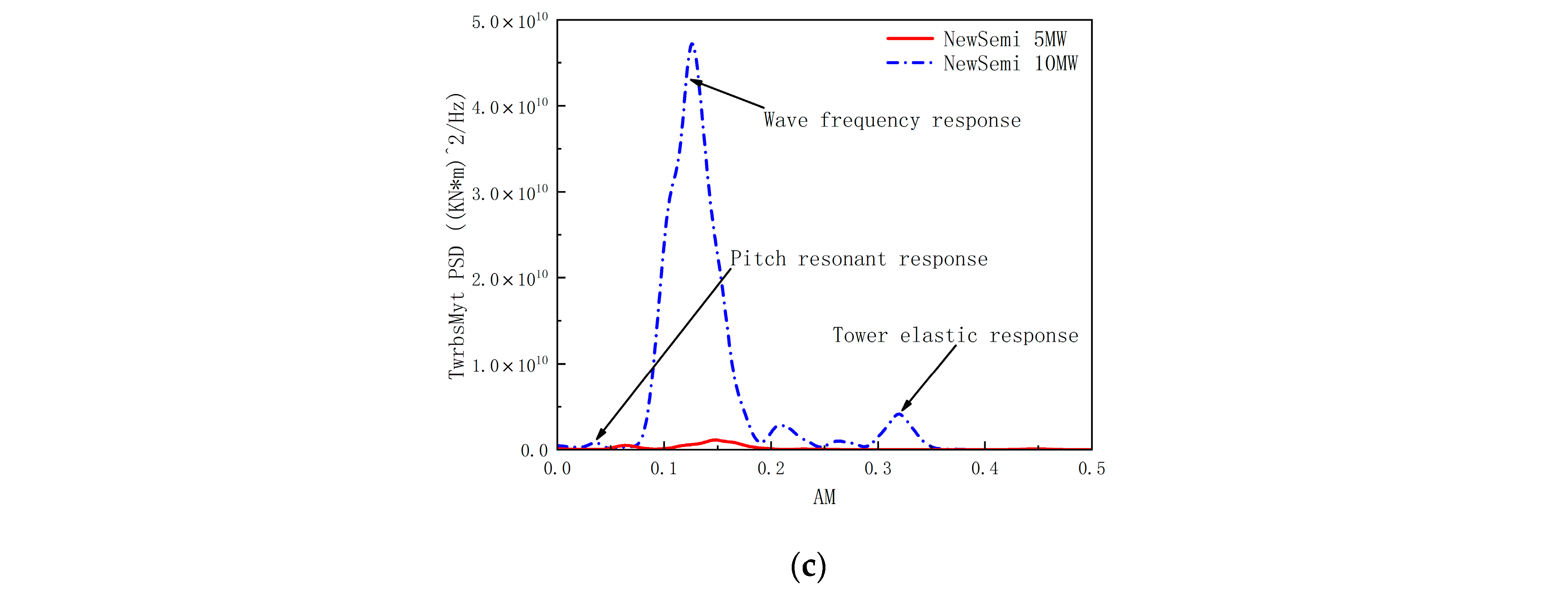
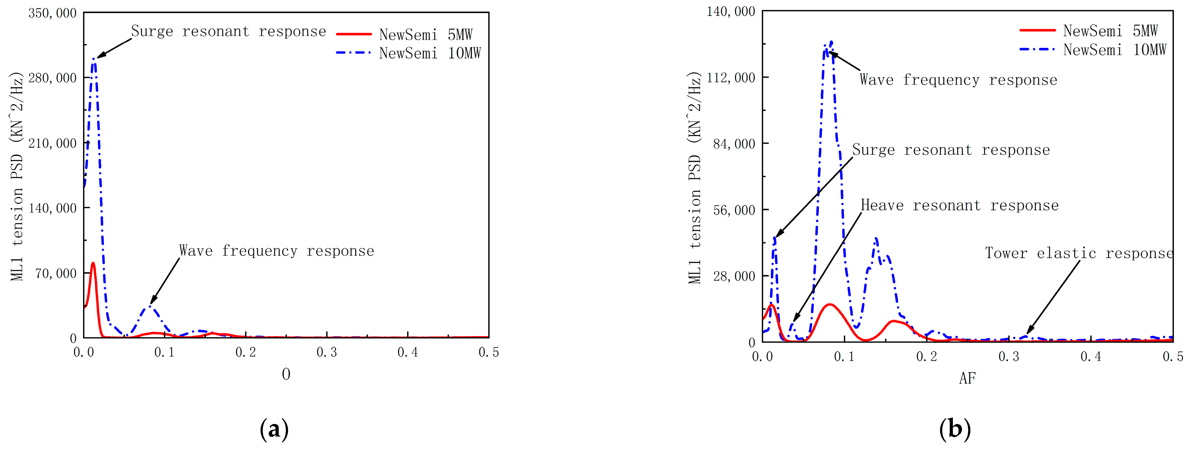
As shown in Figure 15, the downstream leeward mooring line (ML1) was selected for analysis, and the power spectral density of the mooring line tension response for 10 MW and 5 MW FOWTs was compared under the LC5, LC6, and LC7 cases. The low-frequency response of the ML1 tension is significantly greater for the 10 MW FOWT compared to the 5 MW FOWT due to the low-frequency resonance caused by wind loads. This is due to the high wind speed of LC5, at which point the FOWT has not yet reached a shutdown state, and the energy output of the wind load dominates. The two peaks in the response correspond to the natural periods of the FOWT in surge and heave. Additionally, the elastic response of the tower structure has a more pronounced excitation effect on the 10 MW FOWT.
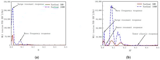
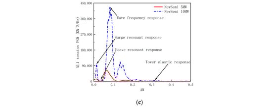
Figure 15.
Comparison of the power spectra of mooring line 1 (ML1) tension response: (a) power spectra of ML1 tension response for the LC5 case; (b) power spectra of ML1 tension response for the LC6 case; (c) power spectra of ML1 tension response for the LC7 case.
In extreme sea conditions with relatively significant high wave heights, the highest peak in the power spectral density of the FOWTs is attributed to wave loads, which have a more significant excitation effect on the ML1 tension response of the 10 MW FOWT. This reflects that under extreme operating conditions of LC6 and LC7, the wind turbine reaches the shutdown requirement, at which point the wind turbine stops generating electricity. Under the excitation of extreme sea conditions, wave loads dominate.
6. Concluding Remarks
This paper introduces a novel semi-submersible 5 MW floating wind turbine (FOWT) called NewSemi, developed to address the V-shaped FOWT’s high-pitch natural frequency issue. This study compares NewSemi’s frequency-domain hydrodynamic and coupled dynamic performance with two established 5 MW FOWTs (V-shaped and Braceless), showing its superiority. Moreover, an optimization method using a differential evolution algorithm scales up NewSemi for a 10 MW turbine, offering an effective approach for designing larger FOWT floaters. The main contributions of this work can be summarized as follows:
- The NewSemi FOWT exhibits a significantly lower-pitch natural frequency than the V-shaped design, avoiding resonance with the dominant wave frequency. It also has the smallest peak RAO response in the pitch direction and more balanced surge and heave responses compared to the V-shaped and Braceless FOWTs;
- Due to the additional floater, among the three FOWTs, the NewSemi platform offers the highest radiation damping in heave and pitch directions, with well-distributed damping coefficients. In the pitch direction, the maximum dimensionless damping of the improved NewSemi exceeds twice that of V-shaped, and achieves a 20% increase in the heave direction.
- Under extreme sea conditions, the NewSemi FOWT achieves substantial motion response reductions, lowering the mean surge and pitch motions by 14.6% and 65.2%, respectively, compared to the Braceless FOWT. Additionally, it exhibits smaller standard deviations in the surge and pitch motions, decreasing by 11.3% and 31.9%, respectively, compared to the V-shaped FOWT. In terms of nacelle acceleration, the NewSemi results in a surge direction under LC5 conditions decreased by 16% compared to V-shaped results, and the results under LC7 conditions decreased by 45.94%;
- The optimized scaling procedure successfully accommodates the DTU 10 MW turbine while maintaining favorable RAO characteristics in the pitch direction. The increased floater size reduces peak frequencies in the surge direction; the natural period of the pitch direction of NewSemi significantly deviates from the wave period of 3–20s, further reducing the possibility of resonance;
- As the FOWT size increases, structural load effects—such as blade root torque, rotor thrust, tower-base-bending moment, and axial force—grow significantly. However, mooring line tensions remain stable, with minimal fluctuations in most cases.
Overall, this study demonstrates the superior performance of the NewSemi FOWT in both a 5 MW and scaled 10 MW configurations, providing a practical engineering solution for designing and optimizing floating support structures for future ultra-large-scale FOWTs. However, this study primarily focuses on the hydrodynamic and structural dynamic performance of the novel FOWT under a limited set of wind and wave conditions. For in-depth research on the NewSemi floater, the use of computational fluid dynamics methods is a very good supplement. As highlighted in [43,44,45], viscous-based CFD codes offer a more detailed and comprehensive understanding of aero-hydrodynamic interactions, which are critical for the accurate modeling of floating wind turbines. The ability to account for viscous effects allows for a more precise simulation of the fluid flow around the turbine and its support structure. It should be noted that this article provides a detailed analysis of the wind wave coupling situation simulated by V-shaped, Braceless, and NewSemi platforms deployed in the South China Sea. The impact of currents was not considered in the analysis, and the next focus of work also includes the full coupling analysis of wind, waves, and currents, providing more reliable guidance for the deployment of NewSemi in the South China Sea.
Author Contributions
Conceptualization, Y.Z. and W.L.; methodology, Y.Z. and W.L.; software, W.S. and C.M.; validation, W.L., W.S., S.W. and C.M.; formal analysis, W.L.; investigation, Y.Z. and X.L.; writing—original draft preparation, Y.Z. and W.L.; writing—review and editing, Y.Z., W.L. and W.S.; supervision, W.S., X.L. and C.M.; project administration, W.S. and X.L. All authors have read and agreed to the published version of the manuscript.
Funding
This research was funded by the Open Fund of State Key Laboratory of Hydraulic Engineering Simulation and Safety, Tianjin University (HESS-1809), and the National Natural Science Foundation of China (grant No. 52071058, 52371268, 51939002, 52001052). This paper was also partially funded by the Key Technology Research and Development Program (2022YFB4201304), the Fundamental Research Funds for the Central Universities (DUT22RC (3)069), and the China Three Gorges Corporation Technology Development Contract (STRI-HT-202403002).
Data Availability Statement
The original contributions presented in this study are included in the article. Further inquiries can be directed to the corresponding author.
Conflicts of Interest
The authors declare no conflicts of interest.
Abbreviations
The following abbreviations are used in this manuscript:
| FOWT | Floating Offshore Wind Turbine |
| RAO | Response Amplitude Operator |
| TLP | Tension Leg Platform |
| WADAM | Wave Analysis by Diffraction and Morison Theory |
| RSM | Response Surface Model |
| NREL | National Renewable Energy Laboratory |
| DTU | Danmarks Tekniske Universitet |
| SIMA | Simulation Workbench for Marine Applications |
| LC | Load Case |
| IEC | International Electrotechnical Commission |
| NTM | Normal Turbulence Model |
| JONSWAP | Joint North Sea Wave Project |
| STD | Standard Deviation |
| DNV | Det Norske Veritas |
| ML | Mooring Line |
| OWC | Oscillating Water Columns |
| TMD | Tuned Mass Damper |
Appendix A
Table A1.
Definitions of nomenclature, Greek symbols, subscripts, superscripts, and acronyms.
Table A1.
Definitions of nomenclature, Greek symbols, subscripts, superscripts, and acronyms.
| Parameters | Definition |
|---|---|
| OC4 | Offshore Code Comparison Collaboration 4 |
| WindFloat | A semi-submersible platform designed by Principle Power |
| Added mass matrix at infinite frequency | |
| Wind force | |
| Linear wave excitation force | |
| Second-order excitation force | |
| Force from the mooring line | |
| Velocity potential | |
| Generalized velocity in the plane motion | |
| Generalized normal vector | |
| Frequency of the incident wave | |
| Wet area of the object’s surface in still water | |
| Lift coefficient of each air foil | |
| Drag coefficient of each air foil | |
| Significant wave height | |
| Spectral peak period | |
| GeniE | A pre-processing software for modeling in the marine engineering industry developed by Det Norske Veritas |
| HydroD | A hydrodynamic calculation software developed by Det Norske Veritas for the marine engineering industry |
References
- Liu, J.; Thomas, E.; Manuel, L. Integrated system design for a large wind turbine supported on a moored semi-submersible platform. J. Mar. Sci. Eng. 2018, 6, 9. [Google Scholar] [CrossRef]
- Beiter, P.; Rand, J.T.; Seel, J. Expert perspectives on the wind plant of the future. Wind Energy 2022, 25, 1363–1378. [Google Scholar] [CrossRef]
- Zhang, R.; Tang, Y.; Hu, J. Dynamic response in frequency and time domains of a floating foundation for offshore wind turbines. Ocean Eng. 2013, 60, 115–123. [Google Scholar] [CrossRef]
- Abid, A.; Shi, W.; Wang, S. Dynamic analysis of TetraSpar floating offshore wind turbine with different tendons failure scenario. Ocean Eng. 2025, 323, 120607. [Google Scholar] [CrossRef]
- Wang, J.; Ren, Y.; Shi, W. Multi-objective optimization design for a 15 MW semisubmersible floating offshore wind turbine using evolutionary algorithm. Appl. Energy. 2025, 377, 124533. [Google Scholar] [CrossRef]
- Seebai, T.; Sundaravadivelu, R. Response analysis of spar platform with wind turbine. Ships Offshore Struct. 2013, 8, 94–101. [Google Scholar] [CrossRef]
- Chen, M.; Huang, W.; Liu, H. A novel SPM wind-wave-aquaculture system: Concept design and fully coupled dynamic analysis. Ocean Eng. 2025, 315, 119798. [Google Scholar] [CrossRef]
- Wang, S.; Xing, Y.; Balakrishna, R. Design, local structural stress, and global dynamic response analysis of a steel semi-submersible hull for a 10-MW floating wind turbine. Eng. Struct. 2023, 291, 116474. [Google Scholar] [CrossRef]
- Robertson, A.; Jonkman, J.; Masciola, M. Definition of the Semisubmersible Floating System for Phase II of OC4; 2014 Technical Report; National Renewable Energy Lab. (NREL): Golden, CO, USA, 2014. [Google Scholar]
- Roddier, D.; Cermelli, C.; Aubault, A. WindFloat: A floating foundation for offshore wind turbines. J. Renew. Sustain. Ener. 2010, 2, 033104. [Google Scholar] [CrossRef]
- Rinaldi, G.; Thies, P.R.; Johanning, L. Current Status and Future Trends in the Operation and Maintenance of Offshore Wind Turbines: A Review. Energies 2021, 14, 2484. [Google Scholar] [CrossRef]
- Luan, C.; Gao, Z.; Moan, T. Design and analysis of a braceless steel 5-mw semi-submersible wind turbine. In Proceedings of the International Conference on Offshore Mechanics and Arctic Engineering, Busan, Republic of Korea, 19–24 June 2016. [Google Scholar]
- Li, W.; Wang, S.; Moan, T. Global design methodology for semi-submersible hulls of floating wind turbines. Renew. Energy 2024, 225, 120291. [Google Scholar] [CrossRef]
- Shi, W.; Li, J.; Michailides, C. Dynamic Load Effects and Power Performance of an Integrated Wind–Wave Energy System Utilizing an Optimum Torus Wave Energy Converter. J. Mar. Sci. Eng. 2022, 10, 1985. [Google Scholar] [CrossRef]
- Li, J.; Shi, W.; Zhang, L. Wind–Wave Coupling Effect on the Dynamic Response of a Combined Wind–Wave Energy Converter. J. Mar. Sci. Eng. 2021, 9, 1101. [Google Scholar] [CrossRef]
- Karimirad, M.; Michailides, C. V-shaped semisubmersible offshore wind turbine: An alternative concept for offshore wind technology. Renew. Energy 2015, 83, 126–143. [Google Scholar] [CrossRef]
- Cao, Q.; Xiao, L.; Cheng, Z. Operational and extreme responses of a new concept of 10 MW semi-submersible wind turbine in intermediate water depth: An experimental study. Ocean Eng. 2020, 217, 108003. [Google Scholar] [CrossRef]
- Karimirad, M. Offshore Energy Structures: For Wind Power, Wave Energy and Hybrid Marine Platforms; Springer: Cham, Switzerland, 2014. [Google Scholar]
- Bossler, A. Floating Offshore Wind Foundations Industry Consortia and Projects in the United States, European and Japan; Main International Consulting LLC: Singapore, 2013; Volume 1, pp. 1–45. [Google Scholar]
- Zhang, J.; Wang, H. Development of offshore wind power and foundation technology for offshore wind turbines in China. Ocean Eng. 2022, 266, 113256. [Google Scholar] [CrossRef]
- Gonçalves, R.T.; Malta, E.B.; Simos, A.N. Influence of Heave Plate on the Flow-Induced Motions of a Floating Offshore Wind Turbine. J. Offshore Mech. Arct. Eng. 2022, 145, 4056345. [Google Scholar] [CrossRef]
- Nagumo, T.; Suzuki, H.; Houtani, H. Experimental and numerical studies on regular wave responses of a very-light FOWT with a guy-wired-supported tower: Effects of wave height, wave direction, and mooring line configuration. Ocean Eng. 2024, 295, 116844. [Google Scholar] [CrossRef]
- Leimeister, M.; Bachynski, E.E.; Muskulus, M. Rational upscaling of a semi-submersible floating platform supporting a wind turbine. Energy Proc. 2016, 94, 434–442. [Google Scholar] [CrossRef]
- Damgaard, M.; Andersen, J.K.F. Natural frequency and damping estimation of an offshore wind turbine structure. In Proceedings of the Twenty-Second International Offshore and Polar Engineering Conference, Rhodes, Greece, 17–22 June 2012. [Google Scholar]
- Wen, B.; Dong, X.; Tian, X. The power performance of an offshore floating wind turbine in platform pitching motion. Energy 2018, 154, 508–521. [Google Scholar] [CrossRef]
- Aboutalebi, P.; Garrido, A.J. Hydrostatic stability and hydrodynamics of a floating wind turbine platform integrated with oscillating water columns: A design study. Renew. Energy 2024, 221, 119824. [Google Scholar] [CrossRef]
- Wang, L.; Bergua, R.; Robertson, A. Experimental investigation of advanced turbine control strategies and load-mitigation measures with a model-scale floating offshore wind turbine system. Appl. Energy 2024, 355, 122343. [Google Scholar] [CrossRef]
- Cheng, Z.; Madsen, H.; Gao, Z. A fully coupled method for numerical modeling and dynamic analysis of floating vertical axis wind turbines. Renew. Energy 2017, 107, 604–619. [Google Scholar] [CrossRef]
- Jonkman, J.M. Dynamics Modeling and Loads Analysis of an Offshore Floating wind Turbine. Master’s Thesis, University of Colorado at Boulder, Boulder, CO, USA, 2007. [Google Scholar]
- Zheng, S.; Antonini, A.; Zhang, Y. Hydrodynamic performance of a multi-oscillating water column (OWC) platform. Appl. Ocean Res. 2020, 99, 102168. [Google Scholar] [CrossRef]
- Sun, X.; Wang, X. Fundamentals of Aeroacoustics with Applications to Aeropropulsion Systems; Elsevier and Shanghai Jiao Tong University Press Aerospace Series; Elsevier: Amsterdam, The Netherlands, 2020. [Google Scholar]
- Duan, W.; Chen, J.; Zhao, B. Second-order Taylor expansion boundary element method for the second-order wave radiation problem. Appl. Ocean Res. 2015, 52, 12–26. [Google Scholar] [CrossRef]
- Frère, A.; Sørensen, N.N.; Hillewaert, K. Discontinuous Galerkin methodology for Large-Eddy Simulations of wind turbine airfoils. J. Physics Conf. Ser. 2016, 753, 022037. [Google Scholar] [CrossRef]
- Lei, S.; Zhang, W.; Lin, J. Frequency domain response of a parametrically excited riser under random wave forces. J. Sound. Vib. 2014, 333, 485–498. [Google Scholar] [CrossRef]
- Moriarty, P.J.; Hansen, A.C. AeroDyn Theory Manual: National Renewable Energy Laboratory Golden; 2005 Technical Report; National Renewable Energy Lab. (NREL): Golden, CO, USA, 2005. [Google Scholar] [CrossRef]
- Aggarwal, N.; Manikandan, R.; Saha, N. Nonlinear short term extreme response of spar type floating offshore wind turbines. Ocean Eng. 2017, 130, 199–209. [Google Scholar] [CrossRef]
- Jiang, J.; Lian, J.; Dong, X. Research on the along-wind aerodynamic damping and its effect on vibration control of offshore wind turbine. Ocean Eng. 2023, 274, 113993. [Google Scholar] [CrossRef]
- Cheng, Y.; Yan, Z.; Pang, L. Probability analysis on the typhoon induced sea states of the South China Sea. In Proceedings of the 2018 OCEANS-MTS/IEEE Kobe Techno-Oceans (OTO), Kobe, Japan, 28–31 May 2018. [Google Scholar]
- Li, G.; Yang, J.; Wu, Z. A sequential optimal Latin hypercube design method using an efficient recursive permutation evolution algorithm. Eng. Optimiz. 2022, 56, 179–198. [Google Scholar] [CrossRef]
- Cao, A.; Shi, X.; Sang, S. Research on Static Analysis of Box Foundation for Wind Turbine on SESAM Software. Wirel. Pers. Commun. 2018, 103, 535–546. [Google Scholar] [CrossRef]
- Clement, C.; Kosleck, S.; Lie, T. Investigation of viscous damping effect on the coupled dynamic response of a hybrid floating platform concept for offshore wind turbines. Ocean Eng. 2021, 225, 108836. [Google Scholar] [CrossRef]
- Bak, C.; Zahle, F.; Bitsche, R. The DTU 10-MW reference wind turbine. In Proceedings of the Danish Wind Power Research 2013, Copenhagen, Denmark, 28 May 2013. [Google Scholar]
- Daabo, A.M.; Alkhabbaz, A.; Ibrahim, S.S. Thirteen vital factors for micro-scale radial turbine vane’s design of geo-solar-powered Brayton cycle applications. Energy Convers. Manag. 2024, 315, 118774. [Google Scholar] [CrossRef]
- Yang, H.-S.; Alkhabbaz, A.; Lee, Y.-H. Integrated CFD and hydrodynamic correction approach for load response analysis of floating offshore wind turbine. Ocean Eng. 2025, 328, 121007. [Google Scholar] [CrossRef]
- Alkhabbaz, A.; Hamza, H.; Daabo, A.M. The aero-hydrodynamic interference impact on the NREL 5-MW floating wind turbine experiencing surge motion. Ocean Eng. 2024, 295, 116970. [Google Scholar] [CrossRef]


Disclaimer/Publisher’s Note: The statements, opinions and data contained in all publications are solely those of the individual author(s) and contributor(s) and not of MDPI and/or the editor(s). MDPI and/or the editor(s) disclaim responsibility for any injury to people or property resulting from any ideas, methods, instructions or products referred to in the content. |
© 2025 by the authors. Licensee MDPI, Basel, Switzerland. This article is an open access article distributed under the terms and conditions of the Creative Commons Attribution (CC BY) license (https://creativecommons.org/licenses/by/4.0/).