Article

Design and Research of a Propulsion-Enabled Station-Keeping Anchoring System Compatible with Shallow-Sea Profiling Floats

1
State Key Laboratory of Marine Geology, Tongji University, Shanghai 200092, China
2
Project Management Office of China National Scientific Seafloor Observatory, Tongji University, Shanghai 200092, China
3
Laoshan Laboratory, Qingdao 266200, China
4
School of Mechanical Engineering, Tongji University, Shanghai 200092, China
5
Shanghai Engineering Research Center of Hadal Science and Technology, College of Engineering Science and Technology, Shanghai Ocean University, Shanghai 201306, China
*
Authors to whom correspondence should be addressed.
J. Mar. Sci. Eng. 2025, 13(5), 860; https://doi.org/10.3390/jmse13050860
Submission received: 14 March 2025 / Revised: 12 April 2025 / Accepted: 23 April 2025 / Published: 25 April 2025
(This article belongs to the Section Ocean Engineering)

Abstract

:
Profiling floats are important platforms for oceanic profile observations, yet they are prone to positional drift and grounding when deployed in shallow-sea environments. In order to address these issues, an aluminum alloy-based propulsion-enabled station-keeping anchoring system (PESKAS) is designed in this paper. The PESKAS comprises anchor wings, thrusters, a steering connector, support frames, and an upper connection flange, which allows easy installation to the bottom of conventional profiling floats. Three anchor wings, with a cone angle of 40° and a length of 0.12 m, enable the attached profiling float to anchor to the seabed under ocean currents of up to 0.5 m/s when fully penetrating the sediment. Numerical simulation results show that achieving full penetration into clay, clayey silt, and silty sand requires thrust forces of 80–100 N, 100–120 N, and 160 N, respectively. To achieve full sediment penetration, the PESKAS employs a redundant quadruple-thruster configuration (total thrust 200 N) with an effective actuation duration of approximately 1 s. It ascends from the seabed via a thruster-generated upward force during the ascent of the profiling float, effectively avoiding grounding. Over a complete operational cycle (descent and ascent), the PESKAS consumes approximately 0.65–1.84 kJ of energy. Compared to the energy consumption of PROVOR profiling float motors (10.25 kJ) and sensors (8.33 kJ), the additional energy requirement for the PESKAS does not have a significant effect on the endurance of profiling floats. According to the results of the simulation experiment of the PESKAS, the system successfully achieves its design objectives of full penetration into and ascending from sediments. PESKAS is a cost-effective solution for the positional drift and grounding of profiling floats, which enables stable long-term profile observations in shallow-sea environments and has broad application prospects.

1. Introduction

Profiling floats are autonomous observation platforms that adjust their depth by changing their buoyancy, and can be equipped with different kinds of sensors for collecting vertical oceanographic data [1,2]. The Array for Real-time Geostrophic Oceanography (ARGO) project has deployed almost 4000 profiling floats for data observations, and has collected more than 2 million profiles over the past 25 years, providing strong support for marine science [3,4,5]. In addition to their deployment in deep-sea regions, the application of profiling floats has gradually extended to shallow-sea environments, including marginal and shelf seas [6]. However, owing to the limited water depth (≤200 m depth [7]) and intensified hydrodynamic forces of shallow-sea environments, profiling floats are susceptible to problems such as being stuck in muddy bottoms [8] and drifting beyond shallow-sea observation regions due to coastal or tidal currents [9,10]. To date, the deployment of profiling floats has been focused mainly on deep-sea environments.
Numerous researchers have focused on developing shallow-sea profiling floats. To address the problems of positional drift caused by ocean currents, Siiriä et al. proposed a motion control strategy in which the float dives close enough to the bottom, but does not contact the sediment, to stay better in the designated area [8]. Wallace et al. utilized a direct seabed contact method that relies on seabed friction to minimize positional drift [11]. Merchel et al. adopted the same approach as Wallace et al. in the Baltic Sea and reported that the profiling floats drifted approximately 0.5–1.43 km/day [12].
To further reduce the drift caused by ocean currents in shallow-sea environments, auxiliary stabilization mechanisms have been designed for profiling floats. For example, the French Research Institute for Exploitation of the Sea (IFREMER) developed the Arvor-C, a 300 m-rated variant derived from the 2000 m Arvor profiling float, by equipping it with anti-drift claws composed of multiple metal rods. This mechanism reduces the daily drift distance of Arvor-C in shallow seas from several kilometers to less than 200 m [13]. Jouffroy adopted a similar approach, utilizing steel claws at the bottom of the profiling float to grip the seabed [14]. McGuire et al. used a simple anchor consisting of a thin stainless steel rod that can sink into the sediment to resist the drift of the TideRider profiling float [15]. Morales-Aragón et al. incorporated a landing platform composed of four stainless steel rods at the bottom of the profiling float “s-Nautilus” to achieve seabed station-keeping and data acquisition [16,17]. In the design of the SMART Float, Viswanathan and Taher used several steel rods as anti-drift claws and enhanced buoyancy adjustment through a ballast chamber to reduce the risk of grounding [18]. The “Dagon” system designed by Yu et al. combined the designs of moored vertical profilers and gliders, equipped with an anchoring mechanism to remain stationary in the seabed during adverse tidal conditions [19]. However, such an anti-drift mechanism is driven by negative buoyancy, and its efficiency might be lost in situations where the seafloor sediment is too hard for the mechanism to grip.
In addition to the use of anti-drift mechanisms to reduce positional drift in shallow-sea environments, external propulsion has been used to correct drift. For example, Le Mezo’s Seabot float was equipped with two thrusters that could be used at the surface to correct its position [20]. The hybrid underwater profiler (HUP) designed by Zhou et al. combines the capacity of the glider and the profiling float to glide to rectify the horizontal displacement offset generated by the ocean current. Additionally, the HUP was equipped with a steel bottom-sitting shelf for landing on the seabed [21]. The Nezha-F, developed by Bai et al., integrates a quadrotor UAV with a profiling float to adjust position through flying on its own [22]. While this type of design enhances mobility and operational performance, it involves more energy consumption.
In shallow-sea environments where profiling floats may be grounded, the release of drop weights has been implemented as a recovery method. The Mid-Depth Lagrangian Float developed by Katz and Groper exemplified this method, which released drop weight via a magnetic coupling mechanism [23]. The Swish Float, designed by Stevens and Pawlowicz, employs galvanic timed release (GTR) to adjust the drop weight to return the float to the surface [24]. A similar method of dropping weight was adopted by Snyder et al., who applied a thruster in addition to floating to provide more force for ascent [25]. However, this design results in the float being unable to continue the observation mission after releasing the drop weight, and can only wait for surface recovery. Other researchers tried to prevent grounding through positive buoyancy designs. For example, the Autonomous Vertical Profiler (AVP) developed by CSIR National Institute of Oceanography used a top-mounted thruster to provide downward force for profiling observations [26]. The profiler designed by Monteiro et al. was similar to AVP, and it had the advantage of enabling rapid profiling observations and anti-grounding capabilities [27]. However, since the thruster must operate continuously, it results in high energy consumption.
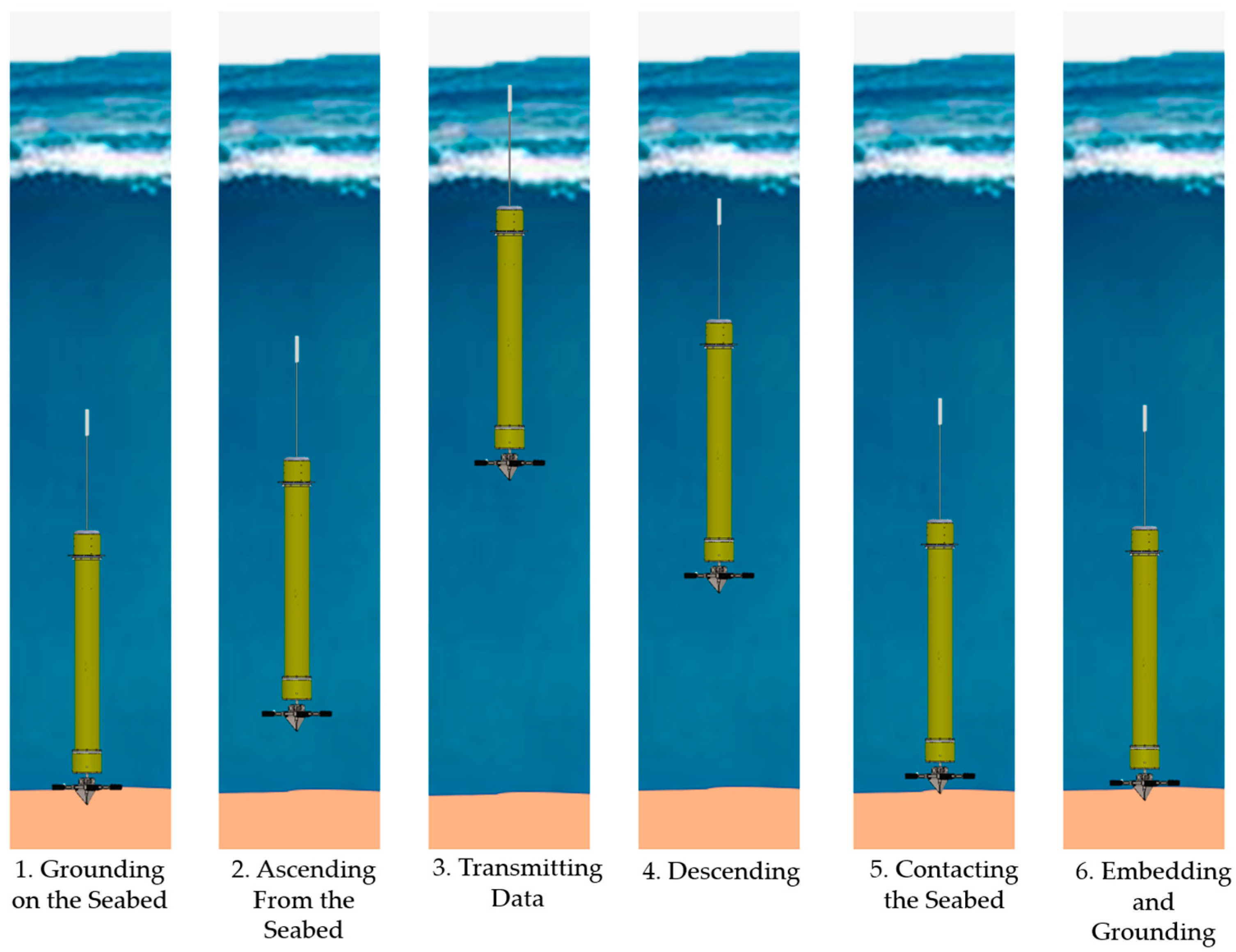
To improve the ability of long-term shallow-sea observations for profiling floats, a novel propulsion-enabled station-keeping anchoring system (PESKAS), which can be installed at the bottom of floats, is designed in this paper. The PESKAS has the following functions: (1) when the profiling float dives to the seabed, the anchor wings of the PESKAS penetrate seafloor sediment with the assistance of the thrusters and provide enough station-keeping force for the float; and (2) when the profiling float needs to ascend from the seabed, the thrusters generate an upward force for the float. Profiling floats equipped with PESKAS can achieve longer-term profiling observations in the shallow sea through/by an operational strategy: conducting measurements during slack tides and remaining anchored to the seabed during other periods.

2. Overall Structure of PESKAS

2.1. Structure of PESKAS

The PESKAS designed in this paper can be installed at the bottom of the profiling floats to reduce the risk of grounding and positional drift. The main components of the PESKAS are anchor wings, thrusters, a steering connector, support frames, and an upper connection flange (Figure 1).
As shown in Figure 1, the bottom of the PESKAS is composed of three anchor wings designed to penetrate seafloor sediment. By using the large lateral projected area of the anchor wings, the PESKAS enhances interaction forces with the sediment, thereby achieving stable seabed anchoring and preventing positional drift. Four symmetrically arranged thrusters provide additional forces: During the descent phase of the profiling float for seabed station-keeping, the thrusters generate downward thrust to fully embed the anchor wings into the sediment with stable anchoring; during the ascent phase, the thrusters generate downward water jets to dislodge sediment and simultaneously produce upward force, which allows the PESKAS to detach from the seabed smoothly and ascend with the profiling float. The anchor wings and thrusters are mounted on support frames, and the steering connector eliminates rigid coupling between the floating bottom and the PESKAS, which can reduce the moment of force caused by ocean currents on the profiling floats. Given the prevalent cylindrical design of modern profiling floats (e.g., Navis, PROVOR [28,29]) with circular base plates, the upper flange (or similar interface) can rapidly connect the PESKAS to the bottom of the float.
The PESKAS has two advantages: (1) compared to anti-drift mechanisms such as anti-drift claws described in Section 1, the anchor wings of the PESKAS have larger lateral surface area, which under full penetration conditions can provide greater station-keeping force for the attached profiling float to effectively enhance the seabed retention stability; and (2) the newly added thrusters can not only ensure the achievement of full penetration for the anchor wings, but also enable the PESKAS to reliably ascend from seabed sediment, thereby reducing the probability of grounding occurrences of the profiling float.

2.2. Operating States of Shallow-Sea Profiling Floats with PESKAS

The profiling float equipped with the PESKAS can adopt a control strategy of ascending for observation and data transmission during slack tide, and then diving to the seabed for station keeping until the next slack tide to resume operations. This strategy enables the float to achieve long-term station-keeping and executes profiling observation tasks within the shallow-sea area. The detailed operating states can be divided into the following six phases (Figure 2).
(1) The profiling float achieves stable seabed station-keeping via PESKAS after being deployed. During this phase, the hydrodynamic force acting on the float is balanced by the seafloor sediment resistance exerted on the anchor wings of the PESKAS.
(2) The profiling float typically ascends according to preset time commands by pumping oil from the internal fuel tank into the external oil bladder through the control system, causing volume expansion and increasing the buoyancy of the float system (including the float body and the PESKAS) to exceed its weight [30]. At this stage, the thrusters of the PESKAS generate downward water jets to disrupt the sediment and provide an upward thrust force to ensure rapid ascent from the seabed; the thrusters stop working once they ascend. The profiling float subsequently ascends under its own net buoyancy while profiling observation data are collected. Ascending during slack tide periods is suggested in this paper to minimize horizontal drift.
(3) After reaching the sea surface, the profiling float extends its satellite antenna above the water to transmit data and receive commands [28].
(4) After the profiling float completes data transmission, the control system pumps oil from the external oil bladder back into the internal fuel tank, causing the weight of the float system (including the profiling float and the PESKAS) to exceed its buoyancy, initiating descent [31].
(5) When the profiling float descends to the seabed, the anchor wings of the PESKAS penetrate the seafloor sediment at a certain depth.
(6) When the pressure sensor of the profiling float remains stable near a specific value for an extended period (indicating seabed contact), the thrusters of the PESKAS provide a downward thrust force, which can fully embed the anchor wings into the sediment. At this phase, the profiling float remains anchored on the seabed, awaiting the next slack tide to ascend for observation and data transmission.

3. Mechanical Model and Design Parameters of the PESKAS

To ensure practical applicability, the float body’s calculation parameters are derived from the Argo-program PROVOR profiling float with its dimensions, mass data, and oil bladder capacity (Table 1), where the minimum buoyancy F f l m i n is the seawater buoyancy of the profiling float on the seabed; the maximum buoyancy F f l m a x is the seawater buoyancy of the profiling float during its ascent; and the float gravity G f l is the gravitational force acting on the float.

3.1. Anchor Wing Station-Keeping Force Analysis

To achieve stable seabed station-keeping, the PESKAS is designed to provide sufficient station-keeping force for profiling floats to counteract the hydrodynamic forces caused by ocean currents. Therefore, the hydrodynamic force should be calculated first to determine the anchor wings’ station-keeping force, F z l . This force is then used to estimate the length l z l and cone angle θ of the anchor wings.
Although the auxiliary stabilization mechanisms of the PESKAS (Figure 1)—including the frames—provide additional support when the float tilts, this paper simplifies the analytical model by focusing solely on the interaction force between the anchor wings and the seabed sediment. A coordinate system is established with the origin O at the contact point between the outermost lower end of the PESKAS thruster and the seafloor sediment surface. The hydrodynamic force F D y and the minimum buoyancy F f l m i n act on the buoyancy center of the profiling float O 1 , where the main float body tilts after being subjected to the hydrodynamic force F D y of ocean current in the positive Y-axis direction; the gravitational force G f l acts on the gravity center of the profiling float O 2 ; the PESKAS anchored in seabed sediments provides the station-keeping force F z l , which acts on the center of steering connector O 3 with an angle σ to the Z-axis. The force diagram of the profiling float during the station-keeping phase is shown in Figure 3.
The force F D y exerted by the shallow-sea ocean current on the profiling float is as follows [33]:
F D y = 1 2 ρ C D 1 u c z 2 A
where ρ denotes the seawater mass density, and 1025 kg/m3 is taken; C D 1 denotes the drag coefficient, which is set to 0.65 on the basis of the American Petroleum Institute (API) recommendation for smooth unshielded cylinders [33]; A denotes the lateral area of the profiling float (approximately 0.32 m2); u c z denotes the ocean current velocity, according to the literature, the seabed current velocity in the East China Sea ranges from 0.3 to 0.4 m/s [34]; in the Baltic Sea, the seabed velocity is primarily 0.1–0.26 m/s, reaching 0.5 m/s under strong wind or storm conditions [35,36]; and in the Mediterranean Sea, the average seabed velocity is 0.03–0.2 m/s [37], with turbulent strait regions reaching 0.27–0.47 m/s [38]; thus, u c z is assigned 0.5 m/s. Therefore, the hydrodynamic force F D y can be calculated as approximately 26 N via Equation (1).
As shown in Figure 3, when the profiling float is in a force equilibrium state,
F D y = F z l sin σ F f l m i n = F z l cos σ + G f l tan σ = F D y F f l m i n G f l
Using the parameters from Table 1 and F D y calculated via Equation (1), the station-keeping force angle σ is calculated as approximately 24°, and the resultant station-keeping force F z l acting on the profiling float is approximately 64 N.

3.2. Design of Anchor Wings

The key parameters of the PESKAS are shown in Figure 4 and Table 2. The included angle between the anchor wings is designed as 120° concerning the OMNI-Max gravity-installed anchor [39]. To prevent distortion of the anchor wings under seafloor sediment resistance, the thickness is determined to be 0.008 m. The vertical distance from the steering connector to the upper surface of the anchor wings h z l and the submerged weight of the PESKAS G z l are set as 0.04 m and 73 N, respectively. Notably, PESKAS works in seawater; therefore, aluminum alloy is selected for PESKAS, which is characterized by low density, high strength, and superior corrosion resistance and is usually used for profiling floats such as PROVOR, APEX, and Deep NINJA [32,40,41].
In Figure 4, the thrusters are simplified as a planar disk-shaped structure to analyze the station-keeping force of the PESKAS. The PESKAS is subjected to the pulling force F l (pulling force from the profiling float opposing the station-keeping force F z l ), the seafloor sediment supporting force F s , its submerged weight G z l , and the seafloor sediment resistance T P . For the anchor wings, the upper section experiences seafloor sediment resistance T P 1 in the negative Y-axis direction, which prevents the PESKAS from sliding in the positive Y-axis direction; the lower section of the anchor wings experiences seafloor sediment resistance T P 2 in the positive Y-axis direction. Since the design target is full penetration, the penetration depth z a is equal to the wing length l z l . Owing to the opposing directions of the resultant resistances T P 1 and T P 2 , a transition point for the direction of sediment resistance exists where the forces of sediment in both positive and negative Y-axis directions are zero, which is assumed to be at a distance a from the sediment surface (Figure 4).
For T P 1 , the equivalent force is applied at the centroid of the upper section of the anchor wings. For T P 2 , the equivalent force is applied at the centroid of the lower section of the anchor wings. L T 1 and L T 2 , the distances from the centroids to the seafloor sediment surface, as shown in Figure 4, can be calculated as follows:
L T 1 = a ( 3 z a 2 a ) 3 ( 2 z a a ) L T 2 = z a + 2 a 3
The equilibrium equations for the PESKAS with a penetration depth z a can be written as follows:
T P 1 = F l sin σ + T P 2 ( L T 2 L T 1 ) T P 2 = F l sin σ ( h z l + L T 1 )
The seafloor sediment resistance T P can be determined via the following formula [42]:
T P = f N c S u A p
where f denotes the shape factor, which is 1.3, as suggested by Neubecker for drag anchors [42]; the bearing capacity coefficient N c is 7.6~11.87 [43]; and S u denotes the undrained shear strength. Therefore, the following expressions can be obtained for T P 1 and T P 2 :
T P 1 = f N c S u A P 1 = ( 3 z a 3 2 a ) a f N c S u tan θ T P 2 = f N c S u A P 2 = 3 2 ( z a a ) 2 f N c S u tan θ
where θ denotes the cone angle of the anchor wings, as shown in Figure 4. Equations (3), (4) and (6) are solved simultaneously with a distance of h z l = 0.04 m (Table 2), an angle of σ = 24°, and a pulling force F l of 64 N. In the context of shallow-sea environments, seafloor sediments include not only clay-dominated sediments, but also clayey silt and silty sand types. The anchor wings of the PESKAS primarily interact with surface sediments, whose undrained shear strength is typically low. For example, the undrained shear strength of surface sediments in the East China Sea is approximately 3–4 kPa [44], and that of the Baltic Sea seafloor surface sediments is about 1–3 kPa [45]. Therefore, the undrained shear strength of sediments in this calculation is set to range from 1 kPa to 5 kPa. By utilizing these parameters, the minimum full penetration depth za required for the anchor wings to resist ocean currents of 0.5 m/s was calculated for cone angles θ varying from 5° to 70°. The results are tabulated in Table 3 and graphically presented in Figure 5.
As shown in Figure 5, the smaller the cone angle θ of the anchor wing is, the greater the minimum full penetration depth z a needed to resist an ocean current of 0.5 m/s. For a significant cone angle θ , the required z a diminishes as the seafloor sediment undrained shear strength increases, with this decline becoming more gradual at larger cone angles θ . Because the typical radii of profiling floats (e.g., Arvor, PROVOR [32,46]) range from 0.06 m to 0.1 m, the external dimensions of the PESKAS’s anchor wings will increase significantly with the increasement of the cone angle θ , and it can reach approximately 0.22 m with the cone angle θ of 70°, which may cause size compatibility problems. Moreover, as the cone angle θ of the anchor wing increases, their contact area with sediments also expands, exhibiting a nonlinear characteristic that follows a tangent function. This consequently leads to increased penetration resistance. Smaller cone angles require greater minimum full penetration depth z a , thus necessitating longer wing lengths which similarly result in size incompatibility. Finally, considering the penetration resistance, size adaptation, and parameters of other structures, such as OMNI-Max front-end wings [39], the cone angle of the anchor wings θ is designed as 40°. Therefore, the minimum z a to achieve full penetration is 0.114 m, and the anchor wing length l z l is 0.12 m.

3.3. Conditions Analysis for Full Penetration of the Anchor Wings into the Seafloor Sediment

The computational results presented in Section 3.1 and Section 3.2 illustrate that the anchor wings of the PESKAS, with a length of 0.12 m and a cone angle of 40°, can provide enough station-keeping force for profiling floats to remain anchored on the seabed under ocean currents of up to 0.5 m/s when fully penetrating the sediment, with undrained shear strengths ranging from 1 to 5 kPa. The conditions required for the full penetration of the anchor wings into the sediments are analyzed in this section.
In the absence of external forces, the anchor wings naturally penetrate the seafloor sediment during the descent of the profiling float. During this penetration process, the anchor wings are subjected primarily to resistance forces, including the end-bearing capacity F b , the frictional resistance F f along the wing sidewalls, and the inertial drag resistance F d (Figure 6). The governing differential equation of motion can be expressed as follows [47]:
m d 2 z 1 d t 2 = W s R f b F b R f f F f F d F γ
where m denotes the total mass of the profiling float and the PESKAS; W s denotes the resultant force of the float and the PESKAS; z 1 denotes the penetration depth with no external force; R f b and R f f denote the strain rate effect coefficients for the end-bearing capacity and frictional resistance; F γ denotes the buoyancy exerted by the soil on the PESKAS, which is equivalent to the weight of displaced seafloor sediment; and t denotes the time of the PESKAS’s motion within the sediment.
The parameters in Equation (7) can be defined as follows [48,49,50]:
F b = N c S u A t = 3 N c S u w z 1 tan θ F f = α S u A s = 1 2 × 6 α S u z 2 tan θ = 3 α S u z 1 2 tan θ F d = 1 2 C d 2   ·   ρ S   ·   A t   ·   v f 2 R f = μ γ ˙ γ ˙ r e f β W s = G f l + G z l F f l m i n
where A t denotes the projected contact area between the anchor wings and seabed sediments along the Z-axis direction, which linearly increases with penetration depth; α denotes the friction coefficient at the anchor wing–sediment interface, assigned 0.35 based on penetration cycle tests of the OMNI-Max model [48]; A s denotes the contact area between the anchor wing sidewalls and the sediment; C d 2 denotes the drag coefficient, influenced by sediment viscosity and the dimensions/shape of the anchor wings, assigned 1.0 for conical wings [49]; and the sediment density ρ S is assigned 1960 kg/m3 [51].
R f denotes the strain rate effect coefficient for different regions of the anchor wings, reflecting variations in resistance [52,53], and μ denotes a dimensionless parameter. Since the strain rate R f f for frictional resistance exceeds that for end-bearing capacity R f b [54,55], μ ≈ 1 for R f b , whereas μ = 2 · 1 β / β for R f f , the strain rate-related coefficient β ranges from 0.13 to 0.17 [48,50]. γ ˙ denotes the shear strain rate, where γ ˙ r e f is the reference shear strain rate, assigned 0.15 s−1 [50,56].
Owing to the small volume of anchor wings, the buoyancy force F γ from seafloor sediment during penetration is negligible. Thus, Equation (7) is simplified as follows:
W s m d 2 z 1 d t 2 = R f b F b + R f f F f + F d
On the basis of energy conservation, Equation (9) can be expressed as follows [48]:
1 2 m V f 2 + W s z 1 = 0 z 1 R f b F b ( z ) + R f f F f ( z ) + F d ( z ) d z  
V f denotes the descending velocity of the profiling float, which is assigned a value of 0.15 m/s because most of the floats have velocities of approximately 0.1~0.2 m/s; for example, the PROVOR can achieve a maximum velocity of approximately 0.1 m/s during 2000 m profiling observations [57], and the Arvor-C float deployed in shallow seas (300 m) has a velocity of 0.15~0.2 m/s [13]. The undrained shear strength S u of seafloor sediment was assigned a value range of 1–5 kPa (Section 3.2).
Solving Equations (8) and (10) simultaneously with relevant parameters, the penetration depth z 1 of the anchor wings is estimated to be approximately 0.04~0.11 m (Figure 7), failing to meet the full penetration design target of 0.12 m. Thus, additional force F t h from the thrusters is required to ensure sufficient penetration depth.
The thrusters can be activated after the PESKAS initially penetrates the sediment under its own momentum, providing supplemental forces F t h . In this case, Equation (10) is modified as follows:
1 2 m V f 2 + W s z 1 + F t h ( z a z 1 ) = 0 z R f b F b ( z ) + R f f F f ( z ) + F d ( z ) d z  
where z a denotes the full penetration depth (0.12 m), and z a z 1 denotes the working distance of the thrusters. Consequently, the thruster force necessary for the anchor wings to achieve full penetration in seafloor sediments can be calculated: for sediments with undrained shear strength S u = 1–5 kPa, the corresponding thruster force F t h ranges from 50 to 162 N, as shown in Figure 7.
The thrusters can also assist the profiling float in ascending from the seabed. To ensure the successful ascent of profiling floats, the sum of the net buoyancy W f and the upward force F t h must exceed the total resistance F a ,
W f = F f l m a x G f l G z l F a < W f + F t h
According to Table 1 and Table 2, substituting the relevant data into Equation (8) allows the calculation of the resultant resistance force F a acting on the anchor wings under full penetration conditions, which is approximately 73~98 N. The profiling float provides a net buoyancy W f of approximately 16 N. Referring to the thruster force required for full penetration of anchor wings into seafloor sediments of varying strengths (Figure 7), the system is designed with sufficient redundancy by configuring thrusters to provide a maximum force of approximately 200 N. Since thruster efficiency decreases with increasing power output [58], employing multiple thrusters reduces individual motor load at equivalent total thrust (thereby decreasing overall power consumption). Considering the dimensional constraints of both the PESKAS and thrusters, a configuration of four thrusters is selected. This configuration ensures uniform thrust distribution while reducing the maximum thrust requirement for individual thrusters, thereby expanding the selection range of compatible thrusters. A maximum thrust output of 50 N per thruster suffices to meet design requirements. When generating an upward force, the thruster-induced water flow disrupts the seabed sediment structure, causing liquefaction and reducing the undrained shear strength [59], thereby further decreasing the resistance during anchor wing ascent from the seabed. This ensures that the PESKAS can successfully ascend from the seafloor.

4. Numerical Simulation and Analysis

Numerical simulation methods are used in this section to validate whether the designed anchor wing length and thruster force can achieve full penetration of the anchor wings of the PESKAS. The coupled Eulerian–Lagrangian (CEL) algorithm is a widely used numerical simulation approach for studying large-deformation interactions between anchor foundations and soil substrates. The algorithm coordinates interactions between Lagrangian and Eulerian meshes, ensuring computational accuracy in deformation zones [60].
This paper uses the CEL algorithm in the nonlinear finite element software Abaqus/CAE 2024 to simulate the penetration process of PESKAS into seafloor sediments. Seafloor sediments are subjected to simultaneous elastic and plastic deformation, with plastic volumetric strain induced by compressive and shear stresses [61]. The Mohr–Coulomb yield criterion in Abaqus is selected as the elastoplastic model for the sediments.
In addition to the clay-dominated sediment types mentioned in Section 3.1, shallow-sea seafloor sediments also include clayey silt and silty sand [62]. Therefore, comparative analyses across different seafloor sediment substrate types have been conducted (Table 4), with the Young’s modulus set to E = 500 S u [56].
To improve the computational convergence rate and simplify the PESKAS model, the simulation framework includes Lagrangian-mesh components (including anchor wings, support frames, and thrusters) and Eulerian-mesh discretized seafloor sediment, with relevant parameters as specified in Table 1, Table 2 and Table 4.
Since the PESKAS is constructed of aluminum alloy with a Young’s modulus significantly higher than that of the surrounding seafloor sediment, the Lagrangian mesh-discretized PESKAS model is set as point-based rigid body constraints [64] to improve the speed of computational convergence. The PESKAS is modeled via ten-node modified tetrahedral elements (C3D10M) to capture structural features accurately, resulting in a total of 15,283 mesh elements.
For Eulerian seafloor sediment, the Eulerian volume fraction (EVF) is calculated to track material flow between Eulerian mesh elements, where an EVF of 1 indicates full material occupation of an element, and 0 indicates no material [65]. Therefore, the seafloor sediment, discretized via eight-node Eulerian integration elements (EC3D8R), is assigned an EVF of 1. The lateral boundaries of the sediment are constrained against horizontal displacement, and the bottom boundary is restrained against any movement in the vertical direction, whereas the upper boundary remains unconstrained. An Eulerian void region with an EVF of 0 is defined at the sediment surface to allow material to flow out of the initial area and to account for surface heave. The Eulerian domain contains 637,000 mesh elements.
Because the volume of the anchor wings is small and the penetration is vertical, the lateral mesh size of the seafloor sediment is set to 4 D (where D is the width of the anchor wings), and the vertical mesh size is set to 8 L (where L is the length of the anchor wings) to minimize the computational cost while maintaining the accuracy of the results. The interaction between Eulerian material (seafloor sediment) and Lagrangian material (PESKAS) is modeled via a general contact algorithm based on the hard contact method [66].
Throughout the simulation analysis, the penetration of the PESKAS from the seafloor sediment surface is simulated with an initial velocity V f applied in the vertically downward direction, and all other directional velocities are set to zero, which aims to reduce the computational burden. This velocity vector constraint simulates the vertical penetration behavior of the PESKAS hitting the seafloor sediment surface at a predetermined velocity [56]. The final finite element model structure is shown in Figure 8.
The descent velocity of the profiling float is fixed at V f = 0.15 m/s (Section 3.3). The simulation results of the penetration depth of the PESKAS under thruster-off conditions across different sediment substrates reveal that the maximum penetration depth of the PESKAS (Figure 9a) tends to decrease because of the progressively increasing undrained shear strength from clay to clayey silt and silty sand. Owing to the elastoplastic deformation of seafloor sediments, the penetration depth peaks at approximately 1 s before slightly decreasing and stabilizing.
Figure 9b shows the velocity variation curve during PESKAS penetration. The results indicate that the velocity begins to decrease upon sediment contact, with faster attenuation observed in substrates with higher undrained shear strength (from clay to clayey silt and silty sand), confirming greater seafloor sediment resistance per unit time in stronger substrates. The simulations indicate that the profiling float’s penetration depth using its own kinetic energy is limited to a penetration depth of 0.05–0.08 m because of sediment resistance, which falls short of the full penetration design target (0.12 m anchor wing length). This necessitates the use of supplemental force from thrusters.
When the PESKAS approaches a stationary state after penetrating the seafloor sediment, the thruster activation is simulated by applying loads to the thruster surfaces with varying magnitudes of thruster force. The simulation results revealed that the penetration depth of PESKAS into the sediment begins to increase after thruster activation, and the penetration depth effectively increases due to external forces. A comparative analysis of Figure 10a–c shows that greater undrained shear strength in the substrates necessitates greater force from the thrusters to achieve equivalent penetration depths. Within the same sediment substrate type, the incremental penetration depth per 20 N increase in propulsion force progressively diminishes beyond 0.1 m, with boundary effects observed to emerge. The final penetration depth stabilizes near 0.1 m.
Based on the simulation results in Figure 10, under both free descent and thruster-activated conditions, the penetration depth of the PESKAS stabilizes after 3 s, with minor fluctuations. The X-direction stress contour plot at 30 s (Figure 11) is selected for conservative analysis. The stress contour plot shows that the penetration of the PESKAS is further hindered because of sediment deformation and uplift, which contacts the bottom of the PESKAS. As shown in Figure 11, the Mises stress in the sediment is primarily distributed near the anchor wings, with the maximum stress concentration (approximately 8   ×   10 3 MPa) occurring at the wing tips where the contact area is the smallest. This phenomenon results from the wing tips compressing and displacing the surrounding sediment, creating lateral expansion and subsequent stress concentration zones. Additionally, significant Mises stress is also present at the interface between the bottom of the PESKAS and the sediment uplift, further demonstrating how this contact inhibits deeper penetration. The Mises stress gradually decreases to about 2   ×   10 3 MPa with increasing radial distance from the wings, indicating diminishing compressive effects on the sediment. At this time, although the 0.12 m long anchor wings of the PESKAS have achieved a penetration depth of only 0.10 m into the sediment, the bottom of the PESKAS has reached the sediment layer, which can be considered fully penetrated. Through comprehensive consideration of thruster power consumption and penetration depth increment, different thruster forces can be configured for different types of seabed sediments. This can be achieved by adjusting the duty ratio to modify current magnitude, while simultaneously activating all four thrusters ensures uniform thrust distribution, with the corresponding total values provided in Table 5.
According to the simulation results in Figure 10, the anchor wings reach their maximum penetration depth within approximately 1 s of thruster activation. For different seafloor sediment substrates (clay, clayey silt, and silty sand), the total force of the four thrusters is set to 80–160 N, with a power consumption range of 325–920 W [58]. Assuming a thruster activation duration of 1 s during penetration and, as analyzed in Section 3.3, a smaller resistance during sediment ascent than during penetration, the ascent phase is also assigned a 1 s activation period for simplified estimation. Consequently, the total energy consumption per operational cycle (including the penetration and ascent phases) is calculated as 0.65–1.84 kJ. Compared with the energy consumption of the PROVOR profiling floats commonly used in the Argo program, which requires approximately 26.28 kJ per operating cycle at 2000 m water depth [29], the energy consumption of each component is shown in Table 6.
A comparison of the energy consumption components in the PROVOR profiling float reveals that the newly added energy consumption from the integrated PESKAS is relatively minor, exhibiting small impact on the overall power consumption of the profiling float.

5. Experiment

In order to validate the engineering applicability of the PESKAS in shallow-sea environments, a simulation experiment was performed in a large water tank in the laboratory. The PESKAS should be installed at the bottom of the profiling float for testing, but the volume of the float was too large to perform the experiment in the water tank. Therefore, in order to simulate the actual force state of the PESKAS installed on the profiling float, the air bag was used to balance part of the gravity of the PESKAS in the water. In the experiment, the sediment of clayey silt, common in shallow sea [44], was chosen to fill the bottom of the water tank to a certain thickness, and then water was added to the tank to a certain depth to simulate the seafloor environment. To make the undrained shear strength of the sediment stronger than 5 kPa, the sediment was compacted before water was added to the tank. The thrusters of the PESKAS were powered by DC regulated power supplies and controlled by a signal generator during the experiment.

5.1. Preparation of Experimental Apparatus

The primary experimental apparatus includes: the PESKAS, an air bag, a force gauge, DC regulated power supplies, a signal generator, an oscilloscope, a water tank, a water pump, and a hoisting crane, as illustrated in Figure 12.
The PESKAS was equipped with four thrusters. The air bag was used to adjust the total force of the PESKAS in the water, which was measured by the force gauge.
DC regulated power supplies (Model: GPD-3303S) provided power to the thrusters of the PESKAS; a signal generator (Model: AFG-2225) controlled the operational states of the motors, while an oscilloscope (Model: SDS 1202X-E) was used to monitor the output signals from the signal generator.
The water tank, with a diameter of 1.58 m and depth of 1 m, was used to hold sediment and water to simulate seafloor environment. The water pump facilitated tank drainage, and the hoisting crane assisted in PESKAS testing operations.

5.2. Experimental Procedure

(1) Buoyancy adjustment. Firstly, we filled the water tank with water. Secondly, we secured the air bag to the top of the PESKAS using straps and put it in the water tank. By adjusting the volume of the air bag, we achieved an overall force of 14 N (according to Table 1 and Table 2) of the PESKAS in the vertically downward direction, as shown in Figure 13a. Finally, we drained the water using the water pump.
(2) Test environment setup. Because the length of the PESKAS’s anchor wings is 0.12 m, the sediment with a thickness of 0.3 m was prepared in the water tank for this experiment, and it could satisfy the full penetration requirements. With the PESKAS’s total height being approximately 0.3 m, the water depth was set at about 0.5 m to meet thruster propulsion needs. The PESKAS was submerged in the water and positioned at the center of the sediment surface using the hoisting crane, as shown in Figure 13b.
(3) Experimental preparation. We connected the positive and negative terminals of the thrusters to the corresponding terminals of the power supply, and enabled the PARA/INDEP mode to obtain higher output current. We connected the positive terminal of the signal generator to the signal line of the thrusters, while establishing a common ground connection between the signal generator’s negative terminal and the power supply’s negative terminal via conducting wires. We configured the signal generator to output a PWM square wave signal with 50 Hz frequency, 3.3 V voltage, and pulse width ranging from 1000 to 2000 μs. Pulse width could be set from 1000 to 1499 μs to obtain the download force, while 1501 to 2000 μs to obtain the upload force. We connected an oscilloscope to the output terminal of the signal generator for real-time monitoring of control signals.
(4) Penetration test. We initialized the thrusters by sending a 1500 μs pulse-width signal from the signal generator. Upon hearing the motor activation sound, we adjusted the pulse width to 1150 μs (total download force of about 115 N) for approximately 1 s before stopping and powering off. Significant water turbidity could be observed during this process (Figure 14a). After maintaining static conditions for a period, we used the water pump to drain the water (Figure 14b). It was shown that the anchor wings of the PESKAS had achieved full penetration in the sediment.
(5) Sediment sampling. Two samples of approximately 20 cm sediment were taken by PC tubes for undrained shear strength test.
(6) Ascending test. Water was carefully replenished to the water tank to 0.5 m depth. Following thruster activation, we adjusted the pulse width to 1850 μs (total upload force of about 100 N) for approximately 1 s before stopping and powering off. It was shown that the PESKAS successfully ascended from the sediment and reached the surface of the water, as shown in Figure 15.
(7) Sediment analysis. The average undrained shear strength of the sediment of 0–12 cm depth was determined by the direct shear apparatus (Model: S-TEC K6520) at Geotechnical and Underground Engineering Laboratory, Tongji University. Test results showed an average undrained shear strength of approximately 6.19 kPa (Table 7).

5.3. Experimental Conclusions

It was shown by the experiment that the PESKAS could successfully achieve complete penetration and controlled ascent in sediment with undrained shear strength of approximately 6.19 kPa. It is demonstrated that the PESKAS can achieve the design objectives and has the engineering applicability in the shallow-sea environment.

6. Conclusions and Prospects

6.1. Conclusions

This paper proposes a novel propulsion-enabled station-keeping anchoring system (PESKAS), which can reduce grounding risks and positional drift of profiling floats deployed in shallow-sea environments. The three anchor wings, which are the core components of PESKAS, were designed with a 40° cone angle and a length of 0.12 m, which can help profiling floats achieve the goal of maintaining seafloor station-keeping under ocean currents of no more than 0.5 m/s when fully penetrating seafloor sediments. To achieve full penetration into the sediment with undrained shear strengths ranging from 1 to 5 kPa, four thrusters that can provide a maximum of 200 N are necessary. The downward force assists PESKAS in fully penetrating sediments to reduce positional drift, whereas the upward force enables the float to ascend from the sediment to avoid grounding. Numerical simulations show that for clay-dominated sediments, clayey silt, and silty sand, thruster forces of 80–100 N, 100–120 N, and 160 N, respectively, are needed for anchor wings of the PESKAS to achieve full penetration in the seabed. An upper connecting flange makes it easy to install profiling floats (e.g., the Argo series). Laboratory tests demonstrate that the PESKAS successfully achieves its design objectives of complete penetration and ascending from the sediment, confirming its feasibility for real-world applicability.
The numerical simulations suggest that the thrusters of the PESKAS with an effective actuation working time of 1 s can achieve full penetration into the sediment or ascend from the seabed. Therefore, the total energy consumption of the PESKAS is estimated to be 0.65–1.84 kJ per cycle. Compared with the energy consumption of PROVOR profiling floats at a depth of 2000 m (26.28 kJ per cycle) [29], PESKAS does not substantially increase the system power consumption of profiling floats; however, it can effectively solve shallow-sea problems such as grounding and positional drift caused by ocean currents.

6.2. Prospects

As of February 2025, 4152 Argo floats have been applied globally (argo.ucsd.edu), suggesting the potential for broad application of PESKAS.
However, real-world shallow-sea environments are more complex. To ensure effective deployment in actual working conditions, special attention should be paid to the following aspects.

6.2.1. Impact of the Sediments

Because of the anchor wings’ requirement for frequent sediment penetration, they are subject to mechanical fatigue and wear from prolonged sediment interaction. Therefore, during the initial design phase, the anchor wings can be structurally thickened to increase their wear allowance.
In practical operations, the PESKAS may encounter sediment conditions with higher undrained shear strength. Under such circumstances, the anchor wings may fail to achieve the complete penetration, which consequently has an impact on the seabed station-keeping stability. Therefore, for higher undrained shear strength sediment conditions, selecting higher-thrust thrusters to achieve stable seabed station-keeping may be a potential solution.
Moreover, actual seabed topography may present uneven conditions that could potentially cause tilting during PESKAS penetration, thereby compromising station-keeping stability. To address this, future implementations may incorporate attitude sensors to monitor the PESKAS’s operational status, with real-time thruster force modulation for active attitude correction.

6.2.2. Impact of the Biofouling Effects

Biofouling effects typically refer to the adhesion of marine organisms, which not only increase the weight of the float [16], but also cause various consequences for the PESKAS, such as elevated energy consumption and hydrodynamic loading [67], reduced operational speed, and shortened service life [68]. Since shallow-sea profiling floats equipped with the PESKAS grounding on the seabed, they are susceptible to biofouling under static conditions [69]. Therefore, antifouling coating systems can be applied to the device’s surface to mitigate biofouling effects in practical applications.

6.2.3. Selection of Batteries and Thrusters

As shown in Table 6, the energy budget of the profiling float includes an item for battery self-discharge, which leads to battery aging over time and causes additional energy loss. The loss of energy from the main battery is temperature dependent, with a typical self-discharge rate of 3% per year [70]. Additionally, prolonged use results in growing internal resistance and passivation, which cause large voltage drops under load [71]. For example, the battery voltage of the Deep Arvor float drops from approximately 9.75 V to about 7.0 V [72]. Consequently, after long-term repeated use, the declining battery voltage reduces output power, leading to diminished thruster force. This may result in insufficient penetration depth of the anchor wings, compromising station-keeping performance. Therefore, selecting higher-performance batteries can extend the service life of the PESKAS.
It is also important to note that since the thrusters frequently interact with sediments during operation, fine sediment particles may infiltrate the motors, causing malfunctions. Thus, choosing thrusters with better sealing or specifically designed anti-silt versions can effectively mitigate such issues.

Author Contributions

Conceptualization, F.J., Q.Y. and Z.M.; investigation, C.G., F.J., Q.Y. and Z.M.; resources, Q.Y., F.J. and Z.M.; data curation, C.G.; writing—original draft preparation, C.G., F.J., Z.M. and Q.Y.; writing—review and editing, C.G., Q.Y., F.J., Z.M. and F.W.; visualization, C.G., F.J., Z.M. and F.W.; supervision, F.J., Q.Y. and Z.M.; project administration, Q.Y. and F.J.; funding acquisition, Q.Y. All authors have read and agreed to the published version of the manuscript.

Funding

This research was sponsored by the National Key Research and Development Program (2018YFC1405803), the China National Scientific Seafloor Observatory (2017-000030-73-01-002437), the Ocean Negative Carbon Emissions (ONCE) Program, and the Interdisciplinary Collaborative Research Project at Tongji University (2023-1-ZD-03 and 2023-1-ZD-04).

Institutional Review Board Statement

Not applicable.

Informed Consent Statement

Not applicable.

Data Availability Statement

The original contributions presented in this study are included in the article. Further inquiries can be directed to the corresponding author.

Acknowledgments

We thank all those who helped write this article and the editors and reviewers of this paper for their constructive feedback.

Conflicts of Interest

The authors declare no conflicts of interest.

Nomenclature

a the distance of the transition point from the sediment surface
Athe lateral area of the profiling float
A s the contact area between the anchor wing sidewalls and the sediment
A t the projected contact area between the anchor wing plates and seabed sediments along the Z-axis direction
C D 1 the drag coefficient
C d 2 the drag coefficient
f the shape factor
F a the resultant resistance force
F b the end-bearing capacity
F d the inertial drag resistance
F D y the hydrodynamic force
F f the frictional resistance
F f l m i n the minimum buoyancy
F f l m a x the maximum buoyancy
F l the reaction force
F s the seafloor sediment supporting force
F t h thrust force
F γ the buoyancy exerted by the soil on the PESKAS
F z l the anchor wings’ station-keeping force
G f l the gravitational force acting on the float
G z l submerged weight
h z l distance from the steering connection point to the upper surface of the anchor wing
L T 1 the distance from the centroid of the upper section to the seafloor sediment surface
L T 2 the distance from the centroid of the lower section to the seafloor sediment surface
l z l the length of the anchor wings
m the total mass of the profiling float and the PESKAS
N c the bearing capacity coefficient
O the origin of the coordinate system
O 1 the buoyancy center of the profiling float
O 2 the gravity center of the profiling float
O 3 the center of steering connector
R f b the strain rate effect coefficient for the end-bearing capacity
R f f the strain rate effect coefficient for the frictional resistance
S u the undrained shear strength
t the time of the PESKAS’s motion within the sediment
T P the seafloor sediment resistance
T P 1 the seafloor sediment resistance of the upper section
T P 2 the seafloor sediment resistance of the lower section
u c z the ocean current velocity
V f the descending velocity of the profiling float
w anchor wing thickness
W f the net buoyancy
W s the resultant force of the float and the PESKAS
z 1 the penetration depth with no external force
z a the penetration depth
α the friction coefficient at the anchor wing–sediment interface
β the strain rate-related coefficient
θ cone angle of the anchor wings
σ the station-keeping force angle
ρ the seawater mass density
ρ S the sediment density
μ a dimensionless parameter
γ ˙ the shear strain rate
γ ˙ r e f the reference shear strain rate

References

  1. Riser, S.C.; Freeland, H.J.; Roemmich, D.; Wijffels, S.; Troisi, A.; Belbéoch, M.; Gilbert, D.; Xu, J.P.; Pouliquen, S.; Thresher, A.; et al. Fifteen years of ocean observations with the global Argo array. Nat. Clim. Change 2016, 6, 145–153. [Google Scholar] [CrossRef]
  2. Roemmich, D.; Johnson, G.C.; Riser, S.; Davis, R.; Gilson, J.; Owens, W.B.; Garzoli, S.L.; Schmid, C.; Ignaszewski, M. The Argo Program Observing the Global Ocean with Profiling Floats. Oceanography 2009, 22, 34–43. [Google Scholar] [CrossRef]
  3. Sharp, J.D.; Fassbender, A.J.; Carter, B.R.; Johnson, G.C.; Schultz, C.; Dunne, J.P. GOBAI-O 2: Temporally and spatially resolved fields of ocean interior dissolved oxygen over nearly two decades. Earth Syst. Sci. Data Discuss. 2023, 15, 4481–4518. [Google Scholar] [CrossRef]
  4. Johnson, G.C.; Hosoda, S.; Jayne, S.R.; Oke, P.R.; Riser, S.C.; Roemmich, D.; Suga, T.; Thierry, V.; Wijffels, S.E.; Xu, J. Argo—Two decades: Global oceanography, revolutionized. Annu. Rev. Mar. Sci. 2022, 14, 379–403. [Google Scholar] [CrossRef] [PubMed]
  5. Nissen, C.; Lovenduski, N.S.; Maltrud, M.; Gray, A.R.; Takano, Y.; Falcinelli, K.; Sauve, J.; Smith, K. LIGHT-bgcArgo-1.0: Using synthetic float capabilities in E3SMv2 to assess spatiotemporal variability in ocean physics and biogeochemistry. Geosci. Model Dev. 2024, 17, 6415–6435. [Google Scholar] [CrossRef]
  6. Notarstefano, G.; Pacciaroni, M.; Kassis, D.; Palazov, A.; Slabakova, V.; Tuomi, L.; Siiriä, S.-M.; Walczowski, W.; Merchel, M.; Allen, J. D6.1: Tailoring of the Controlling and Monitoring Tools for Operations in Shallow Coastal Waters. 2021. Available online: https://hdl.handle.net/20.500.14083/35943 (accessed on 11 April 2025).
  7. Barge, L.M.; Price, R.E. Diverse geochemical conditions for prebiotic chemistry in shallow-sea alkaline hydrothermal vents. Nat. Geosci. 2022, 15, 976–981. [Google Scholar] [CrossRef]
  8. Siiria, S.; Roiha, P.; Tuomi, L.; Purokoski, T.; Haavisto, N.; Alenius, P. Applying area-locked, shallow water Argo floats in Baltic Sea monitoring. J. Oper. Oceanogr. 2019, 12, 58–72. [Google Scholar] [CrossRef]
  9. Shon, C. Developing Parameter Estimation Techniques for Controller Optimization of a Coastal Profiling Float. MBARI Intern Report 2013. Available online: https://www.mbari.org/wp-content/uploads/2015/10/Sohn.pdf (accessed on 11 April 2025).
  10. Barker, L. Closed-loop buoyancy control for a coastal profiling float. MBARI Intern Rep. 2014, 1–15. Available online: https://www.mbari.org/wp-content/uploads/2015/10/Barker_Laughlin.pdf (accessed on 11 April 2025).
  11. Wallace, L.O.; van Wijk, E.M.; Rintoul, S.R.; Hally, B. Bathymetry-Constrained Navigation of Argo Floats Under Sea Ice on the Antarctic Continental Shelf. Geophys. Res. Lett. 2020, 47, e2020GL087019. [Google Scholar] [CrossRef]
  12. Merchel, M.; Walczowski, W.; Rak, D.; Wieczorek, P. The use of Argo Hoats as virtual moorings for monitoring the South Baltic Sea. Oceanologia 2024, 66, 99–110. [Google Scholar] [CrossRef]
  13. André, X.; Le Reste, S.; Rolin, J.-F. Arvor-C: A coastal autonomous profiling float. Sea Technol. 2010, 51, 10–13. [Google Scholar]
  14. Jouffroy, J.; Zhou, Q.; Zielinski, O. On active current selection for Lagrangian profilers. Model. Identif. Control. 2013, 34, 1–10. [Google Scholar] [CrossRef]
  15. McGuire, P.; Jakuba, M.; Partan, J. TideRider: A Low-Cost Coastal Profiling Float. In Proceedings of the OCEANS Conference, Limerick, Ireland, 5–8 June 2023; IEEE: Piscataway, NJ, USA. [Google Scholar]
  16. Morales-Aragon, I.P.; Gimenez-Gallego, J.; Gilabert, J.; Torres-Sanchez, R.; Soto-Valles, F. Design and application of depth control methods for autonomous underwater profilers in challenging marine environments. Results Eng. 2025, 25, 104031. [Google Scholar] [CrossRef]
  17. Morales-Aragon, I.P.; Gilabert, J.; Torres-Sanchez, R.; Soto-Valles, F. Design and development of a new stand-alone profiler for marine monitoring purposes. Appl. Ocean. Res. 2024, 152, 104199. [Google Scholar] [CrossRef]
  18. Viswanathan, V.; Taher, T. Buoyancy Driven Autonomous Profiling Float for Shallow Waters. In Proceedings of the MTS/IEEE Oceans Conference, Monterey, CA, USA, 19–23 September 2016; IEEE: Piscataway, NJ, USA. [Google Scholar]
  19. Tolstonogov, A.Y.; Fries, D.; Storozhenko, V.A.; Pryazhennikov, P.I. The Dagon System: A Modular AUV for Long-term Monitoring and Observation. In Proceedings of the OCEANS Conference, Electr Network, Porto, Portugal, 20–23 September 2021; IEEE: Piscataway, NJ, USA. [Google Scholar]
  20. Le Mezo, T.; Le Maillot, G.; Ropert, T.; Jaulin, L.; Ponte, A.; Zerr, B. Design and control of a low-cost autonomous profiling float. Mech. Ind. 2020, 21, 512. [Google Scholar] [CrossRef]
  21. Zhou, P.; Yang, C.; Wu, S.; Zhu, Y. Designated Area Persistent Monitoring Strategies for Hybrid Underwater Profilers. IEEE J. Ocean. Eng. 2020, 45, 1322–1336. [Google Scholar] [CrossRef]
  22. Bai, Y.; Jin, Y.; Liu, C.; Zeng, Z.; Lian, L. Nezha-F: Design and Analysis of a Foldable and Self-Deployable HAUV. IEEE Robot. Autom. Lett. 2023, 8, 2309–2316. [Google Scholar] [CrossRef]
  23. Katz, Y.; Groper, M. On the Development of a Mid-Depth Lagrangian Float for Littoral Deployment. J. Mar. Sci. Eng. 2022, 10, 2030. [Google Scholar] [CrossRef]
  24. Stevens, S.W.; Pawlowicz, R. Swish Floats: An Inexpensive Neutrally Buoyant Float to Monitor Dispersion in Coastal Seas. J. Atmos. Ocean. Technol. 2023, 40, 1493–1508. [Google Scholar] [CrossRef]
  25. Snyder, W.; Roman, C.; Licht, S. Hybrid actuation with complementary allocation for depth control of a Lagrangian sea-floor imaging platform. J. Field Robot. 2018, 35, 330–344. [Google Scholar] [CrossRef]
  26. Afzulpurkar, S.; Navelkar, G.; Desa, E.; Madhan, R.; Dabholkar, N.; Prabhudesai, S.; Mascarenhas, A. Autonomous vertical profiler data management. In Proceedings of the Trends in Intelligent Robotics: 13th FIRA Robot World Congress, FIRA 2010, Bangalore, India, 15–17 September 2010; pp. 17–24. [Google Scholar]
  27. Monteiro, J.M.; Cruz, N.A. Development of an Autonomous Underwater Profiler for Coastal Areas. In Proceedings of the Conference on OCEANS, Anchorage, AK, USA, 18–21 September 2017; IEEE: Piscataway, NJ, USA. [Google Scholar]
  28. André, X.; Le Traon, P.-Y.; Le Reste, S.; Dutreuil, V.; Leymarie, E.; Malardé, D.; Marec, C.; Sagot, J.; Amice, M.; Babin, M. Preparing the new phase of argo: Technological developments on profiling floats in the NAOS project. Front. Mar. Sci. 2020, 7, 577446. [Google Scholar] [CrossRef]
  29. Bittig, H.C.; Maurer, T.L.; Plant, J.N.; Schmechtig, C.; Wong, A.P.S.; Claustre, H.; Trull, T.W.; Bhaskar, T.V.S.U.; Boss, E.; DallOlmo, G.; et al. A BGC-Argo Guide: Planning, Deployment, Data Handling and Usage. Front. Mar. Sci. 2019, 6, 502. [Google Scholar] [CrossRef]
  30. Wang, Q.; Qiu, Z.; Yang, S.; Li, H.; Li, X. Design and experimental research of a novel deep-sea self-sustaining profiling float for observing the northeast off the Luzon Island. Sci. Rep. 2022, 12, 18885. [Google Scholar] [CrossRef]
  31. Xue, G.; Liu, Y.; Si, W.; Ji, C.; Guo, F.; Li, Z. Energy recovery and conservation utilizing seawater pressure in the working process of Deep-Argo profiling float. Energy 2020, 195, 116845. [Google Scholar] [CrossRef]
  32. Sagot, J. PROVOR ProvBio-II UTI User Maual; RevDate:04092013; NKE Instrumentation: Hennebont, France, 2013; pp. 1–66. [Google Scholar]
  33. Institute, A.P. Recommended Practice for Planning, Designing, and Constructing Fixed Offshore Platforms-Working Stress Design: Upstream Segment. API Recommended Practice 2A-WSD (RP 2A-WSD): Errata and Supplement 1, December 2002; American Petroleum Institute. 2000. Available online: https://www.academia.edu/105904042/Recommended_Practice_for_Planning_Designing_and_Constructing_Fixed_Offshore_Platforms_Working_Stress_Design (accessed on 11 April 2025).
  34. Chu, Q.-Q.; Zhang, X.; Sun, J. Numerical simulation of the tidal current in the East China Sea. Mar. Forecast. 2015, 32, 51–60. [Google Scholar]
  35. Liblik, T.; Rak, D.; Siht, E.; Väli, G.; Karstensen, J.; Tuomi, L.; Biddle, L.C.; Lilover, M.-J.; Skudra, M.; Naumann, M. Current structure, circulation and transport in the Central Baltic Sea observed by array of moorings and gliders. EGUsphere 2024, 2024, 2272. [Google Scholar]
  36. Ambrosimov, A.; Yakubov, S.K.; Babakov, A.; Chubarenko, B. Water wave motions in the bottom layer of shallow water areas (on the example of the Vistula Lagoon in the Baltic Sea). Russ. Meteorol. Hydrol. 2015, 40, 259–268. [Google Scholar] [CrossRef]
  37. Poulos, S.E. The contribution of near-bed currents to modern sedimentation processes in the deep waters of the Hellenic Arc-Trench system, eastern Mediterranean. Geo-Mar. Lett. 2001, 20, 201–208. [Google Scholar]
  38. Falcini, F.; Salusti, E. Friction and mixing effects on potential vorticity for bottom current crossing a marine strait: An application to the Sicily Channel (central Mediterranean Sea). Ocean. Sci. 2015, 11, 391–403. [Google Scholar] [CrossRef]
  39. Shelton, J.T. OMNI-Maxtrade anchor development and technology. In Proceedings of the OCEANS, Vancouver, BC, Canada, 29 September–4 October 2007; pp. 1–10. [Google Scholar]
  40. Le Reste, S.; Gould, J. Euro-Argo, Technologie des profileurs. Del. n° 4.2. 1. 2011. Available online: https://archimer.ifremer.fr/doc/00213/32417/ (accessed on 11 April 2025).
  41. Kobayashi, T.; Asakawa, K.; Kawano, T.; Hyakudome, T.; Matsuura, M.; Amaike, K.-i.; Watanabe, K.; Ino, T.; Suga, T. Deep NINJA: A new profiling float for deep ocean observation. In Proceedings of the ISOPE International Ocean and Polar Engineering Conference, Rhodes, Greece, 17–22 June 2012; p. ISOPE-I-12-256. [Google Scholar]
  42. Neubecker, S.; Randolph, M. The performance of drag anchor and chain systems in cohesive soil. Mar. Georesources Geotechnol. 1996, 14, 77–96. [Google Scholar] [CrossRef]
  43. Peng, J.; Liu, H. Analytical study on comprehensive behaviors of drag anchors in the seabed. Appl. Ocean. Res. 2019, 90, 101855. [Google Scholar] [CrossRef]
  44. Duan, X.; Yin, P.; Liu, J.; Cao, K.; Gao, F.; Chen, X. Modern sedimentation environments in the coastal zone of East China. Mar. Geol. Quat. Geol. 2019, 39, 14–20. [Google Scholar] [CrossRef]
  45. Lu, T. Statistical Analysis and Correlation of Physical and Geotechnical Properties of Marine Sediments in Eckernfoerde Bay, Baltic Sea. Ph.D. Thesis, Texas A&M University, College Station, TX, USA, 1996. [Google Scholar]
  46. Instrumentation, N. High & Low Depth Profiling Floats. Available online: https://nke-instrumentation.com/high-low-depth-profiling-floats/ (accessed on 2 February 2025).
  47. True, D.G. Penetration of Projectiles into Seafloor Soils. 1975. Available online: https://apps.dtic.mil/sti/tr/pdf/ADA011808.pdf (accessed on 2 February 2025).
  48. Han, C.; Liu, J. Model tests on the penetration depth of gravity installed plate anchors. Ocean. Eng. 2016, 34, 92–100. [Google Scholar] [CrossRef]
  49. True, D.G. Undrained Vertical Penetration into Ocean Bottom Soils. Ph.D. Theses, University of California, Berkeley, CA, USA, 1976. [Google Scholar]
  50. O’loughlin, C.; Richardson, M.; Randolph, M.; Gaudin, C. Penetration of dynamically installed anchors in clay. Géotechnique 2013, 63, 909–919. [Google Scholar] [CrossRef]
  51. Lu, B.; Li, Q.; Huang, S.; Zhang, F. The Comparing of seabed sediment acoustic-physical properties in the Yellow Sea, the East China Sea and northern the South China Sea. J. Ocean. Technol. 2005, 24, 28–33. [Google Scholar]
  52. Nie, C.; Shelton, J.T. Prediction of gravity installed anchors installation penetration. In Proceedings of the OCEANS’11 MTS/IEEE KONA, Waikoloa, HI, USA, 19–22 September 2011; pp. 1–5. [Google Scholar]
  53. Fu, Y.; Liu, Y. Experimental and theoretical investigations on fin configuration effects of dynamically installed anchors in clay. Can. Geotech. J. 2021, 58, 1527–1542. [Google Scholar] [CrossRef]
  54. Steiner, A.; Kopf, A.J.; L’Heureux, J.-S.; Kreiter, S.; Stegmann, S.; Haflidason, H.; Moerz, T. In situ dynamic piezocone penetrometer tests in natural clayey soils—A reappraisal of strain-rate corrections. Can. Geotech. J. 2014, 51, 272–288. [Google Scholar] [CrossRef]
  55. Chow, S.; O’loughlin, C.; Randolph, M. Soil strength estimation and pore pressure dissipation for free-fall piezocone in soft clay. Géotechnique 2014, 64, 817–827. [Google Scholar] [CrossRef]
  56. Dastider, A.G.; Mana, D.S.; Chatterjee, S.; Basu, P. Prediction of Maximum Penetration Depth for Free Fall Ball Penetrometers in Clay. In Proceedings of the ISOPE International Ocean and Polar Engineering Conference, Sapporo, Japan, 10−15 June 2018; p. ISOPE-I-18-679. [Google Scholar]
  57. Cabanes, C.; Thierry, V. Surface Data of PROVOR/ARVOR floats based on Coriolis GDAC at 08/03/2013. 2013. Available online: https://agris.fao.org/search/en/providers/123887/records/66d9b627f995ef9c0425419d (accessed on 2 February 2025).
  58. Carneiro, J.F.; Pinto, J.B.; de Almeida, F.G.; Cruz, N.A. Depth Control of an Underwater Sensor Platform: Comparison between Variable Buoyancy and Propeller Actuated Devices. Sensors 2024, 24, 3050. [Google Scholar] [CrossRef]
  59. Lin, J.; Jeng, D.-S.; Zhao, H.; Gao, Y.; Liu, J.; Guo, Y. Recent advances of seabed liquefaction around the vicinity of marine structures. Ocean. Eng. 2023, 280, 114660. [Google Scholar] [CrossRef]
  60. Noh, W.F. CEL: A Time-Dependent, Two-Space-Dimensional, Coupled Eulerian-Lagrange Code; Lawrence Livermore National Lab: Livermore, CA, USA, 1963.
  61. Sha, F.; Xi, M.; Chen, X.; Liu, X.; Niu, H.; Zuo, Y. A recent review on multi-physics coupling between deep-sea mining equipment and marine sediment. Ocean. Eng. 2023, 276, 114229. [Google Scholar] [CrossRef]
  62. Guo, X.; Liu, X.; Zhang, H.; Shan, Z.; Sun, M. Improved predictive model for the strength of fluidized seabed sediments with rate effect characteristics by full-scale spherical penetrometer tests. Comput. Geotech. 2023, 161, 105535. [Google Scholar] [CrossRef]
  63. Lu, L.; Ma, L. Acoustic characteristics of the seabed. Physics 2014, 43, 717–722. [Google Scholar]
  64. Sheng, D.C.; Eigenbrod, K.D.; Wriggers, P. Finite element analysis of pile installation using large-slip frictional contact. Comput. Geotech. 2005, 32, 17–26. [Google Scholar] [CrossRef]
  65. Zhao, Y.B.; Liu, H.X. Key Techniques in Simulating Comprehensive Anchor Behaviors by Large Deformation Finite Element Analysis. J. Offshore Mech. Arct. Eng.-Trans. Asme 2018, 140, 012001. [Google Scholar] [CrossRef]
  66. Yang, Y.C.; Liu, H.X.; Zhao, Y.B. The pullout capacity of OMNI-Max anchors in clay. Ocean. Eng. 2021, 230, 109063. [Google Scholar] [CrossRef]
  67. Theophanatos, A.; Wolfram, J. Hydrodynamic Loading on Macro-Roughened Cylinders of Various Aspect Ratios. J. Offshore Mech. Arct. Eng. 1989, 111, 214–222. [Google Scholar] [CrossRef]
  68. Chasse, K.R.; Scardino, A.J.; Swain, G.W. Corrosion and fouling study of copper-based antifouling coatings on 5083 aluminum alloy. Prog. Org. Coat. 2020, 141, 105555. [Google Scholar] [CrossRef]
  69. Scardino, A.J.; Fletcher, L.E.; Lewis, J.A. Fouling control using air bubble curtains: Protection for stationary vessels. J. Mar. Eng. Technol. 2009, 8, 3–10. [Google Scholar] [CrossRef]
  70. Riser, S.C.; Swift, D.; Drucker, R. Profiling Floats in SOCCOM: Technical Capabilities for Studying the Southern Ocean. J. Geophys. Res.Ocean. 2018, 123, 4055–4073. [Google Scholar] [CrossRef]
  71. Gordon, L.; McClune, M.; Dufour, J. Tadiran HLCs Extend Battery Life for Oceanographic Deployments. In Proceedings of the MTS/IEEE Oceans Conference, Monterey, CA, USA, 19–23 September 2016; IEEE: Piscataway, NJ, USA. [Google Scholar]
  72. Vélez-Belchí, P. Deep float experiment final evaluation. Centro Oceanográfico de Canarias 2016. Available online: http://hdl.handle.net/10261/318583 (accessed on 2 February 2025).
Figure 1. Structural schematic of the PESKAS (left: overall integration schematic; right: 3D schematic of the PESKAS).
Jmse 13 00860 g001
Figure 2. Operating states of shallow-sea profiling floats.
Jmse 13 00860 g002
Figure 3. Force diagram of the profiling float during the seabed station-keeping phase.
Jmse 13 00860 g003
Figure 4. Force diagram of the PESKAS.
Jmse 13 00860 g004
Figure 5. Minimum required full penetration depth z a of the cone angles θ = 5–70° of anchor wings for resisting 0.5 m/s ocean current in sediments with undrained shear strength S u = 1–5 kPa.
Jmse 13 00860 g005
Figure 6. Force diagram of the PESKAS penetrating sediments with the thrusters in non-operational state.
Jmse 13 00860 g006
Figure 7. Required thruster force F t h for full penetration of anchor wings into sediments with undrained shear strength S u = 1~5 kPa and their penetration depth z 1 into sediments without thruster assistance.
Jmse 13 00860 g007
Figure 8. Finite element model.
Jmse 13 00860 g008
Figure 9. Depth and velocity profiles of float penetration into sediments under thruster-off conditions, the velocity V f of the PESKAS is set to 0.15 m/s.
Jmse 13 00860 g009
Figure 10. Penetration depth curves of the PESKAS operating at velocity V f = 0.15 m/s with thruster force F t h set to 60–160 N under thruster-activated conditions.
Jmse 13 00860 g010
Figure 11. X-Direction stress contour plot of the PESKAS at 30 s.
Jmse 13 00860 g011
Figure 12. Main experimental apparatus for penetration and ascending testing of the PESKAS.
Jmse 13 00860 g012
Figure 13. (a) Buoyancy adjustment. (b) Test environment setup.
Jmse 13 00860 g013
Figure 14. (a) Water status after PESKAS thruster activation. (b) PESKAS status after draining the water.
Jmse 13 00860 g014
Figure 15. PESKAS successfully surfaces after thruster activation.
Jmse 13 00860 g015
Table 1. Calculation parameters for profiling floats.
Float LengthFloat Diameter Float   Gravity   G f l Minimum   Buoyancy   F f l m i n Maximum   Buoyancy   F f l m a x
1.7 m0.19 m431 N490 N520 N
Note: The calculation parameters are based on references [29,32].
Table 2. Key parameters of the PESKAS.
NameParameters
Anchor   wing   thickness   w 0.008 m
Included angle between two anchor wings120°
Distance   h z l from the steering connection point to the upper surface of the anchor wing0.04 m
Submerged   weight   G z l of the PESKAS73 N
Material of the PESKASAluminum alloy
Table 3. Minimum required full penetration depth z a of the cone angles θ = 5–70° of anchor wings for resisting 0.5 m/s ocean current in sediments with undrained shear strength S u = 1–5 kPa.
Anchor   Wings   Penetration   Depth   z a (m)
The   Cone   Angle   θ of the Anchor Wings Seafloor   Sediment   Undrained   Shear   Strength   S u (kPa)
12345
0.2990.2200.1840.1630.149
10°0.2190.1630.1370.1220.111
20°0.1610.1200.1020.0910.084
30°0.1320.1000.0850.0760.070
40°0.1140.0860.0740.0660.061
50°0.0990.0750.0640.0580.053
60°0.0850.0650.0560.0500.046
70°0.0710.0550.0470.0420.039
Table 4. Physical and mechanical parameters of seafloor sediment substrates [44,56,63].
No.Substrate Type Density   ρ S (kg/m3) Undrained   Shear   Strength   S u (kPa)Friction AnglePoisson’s Ratio
1Clay19702.37140.45
2Clayey Silt18003180.4
3Silty Sand17834.6200.3
Table 5. Required thruster forces for different types of seafloor sediment substrates.
Substrate TypeClayClayey SiltSilty Sand
Thruster Force (N)80~100100~120160
Table 6. Energy budget estimate on a per profile basis for PROVOR floats.
SystemBuoyancy PumpElectronicsIridium-GPSSensors *Battery Self-DischargeTotal Energy Use
Energy (kJ/profile)10.255.421.138.331.1526.28
* Note: sensors includes nitrate sensor, radiometry, CTD sensor, oxygen sensor and flbb sensor.
Table 7. The undrained shear strength of the sediment of 0–12 cm depth.
Depth (cm)The Strength of Sample 1 (kPa)The Strength of Sample 2 (kPa)
0–35.795.83
3–66.156.05
6–96.366.33
9–126.546.50
Average6.19
Disclaimer/Publisher’s Note: The statements, opinions and data contained in all publications are solely those of the individual author(s) and contributor(s) and not of MDPI and/or the editor(s). MDPI and/or the editor(s) disclaim responsibility for any injury to people or property resulting from any ideas, methods, instructions or products referred to in the content.

