Article

Towing Resistance and Design of a Towing Scheme for a Floating Wind Turbine

1
China Gezhouba Group Electric Power Co., Ltd., Yichang 443002, China
2
School of Naval Architecture, Ocean and Energy Power Engineering, Wuhan University of Technology, Wuhan 430063, China
*
Author to whom correspondence should be addressed.
J. Mar. Sci. Eng. 2025, 13(4), 789; https://doi.org/10.3390/jmse13040789
Submission received: 16 March 2025 / Revised: 10 April 2025 / Accepted: 10 April 2025 / Published: 16 April 2025
(This article belongs to the Section Marine Energy)

Abstract

:
Towing operation is an important part of the transportation and installation of offshore floating wind turbines. The study of towing resistance is of great significance to the efficient construction of floating wind turbine towing. This paper takes the floating wind turbine model designed by “China Energy Construction Group Guangdong Electric Power Design Institute Co., Ltd.” as the research object, uses STAR-CCM+ 2302 software to establish the computational domain model of floating wind turbine towing, and compares it with the existing physical model experimental results and empirical formula calculation results to verify the accuracy of the CFD resistance prediction method; then the method is used to calculate the still water towing resistance of the new large-megawatt floating wind turbine at different drafts and speeds, and according to the resistance calculation results, the integrated towing system of the floating wind turbine is established in ANSYS-AQWA (Version 2023 R1), the influence of environmental loads on towing resistance is analyzed, and the selection basis of tugboat is proposed. The results show that towing resistance is closely related to the draft, speed, and foundation configuration of the wind turbine platform. In order to ensure the safety of the towing system, the speed should be kept below 4 kn. The experimental results are compared and verified that the calculation results of this method are close to the experimental values and the empirical formula calculation values, which realizes the rapid prediction of the towing resistance of the floating wind turbine and provides guidance for the towing operation of the offshore floating wind turbine platform.

1. Introduction

With the continuous growth of global energy demand and the high attention to renewable energy, offshore wind power, as a green and clean energy form, is becoming an important part of the global energy transformation [1]. In particular, the emergence of floating wind turbines (FOWT) provides new possibilities for installation in complex waters, such as offshore and deep waters. However, compared with fixed wind turbines, floating wind turbines face more technical challenges in design, towing, and operation and maintenance, including dynamic stability, system response characteristics, and long-term reliability [2]. Jiang et al. [3,4,5] discussed and analyzed the foundation types, installation technologies, and operation and maintenance (O and M) of FOWT, highlighting the challenges faced by FOWTs and future research directions. Similarly, Hu et al. [6] presented a comprehensive review on the key technologies related to the installation, operation, and maintenance of FOWT and provided a summary of the challenges and future development directions.
These challenges bring an urgent need to conduct in-depth research on the overall performance of floating wind turbines during towing operations. In recent years, the academic and engineering communities have made significant progress in the research of floating wind turbine towing stability and proposed a variety of new evaluation methods and optimization strategies, which provide a solid theoretical basis for the stability and reliability of floating wind turbines. Researchers have established a series of numerical models to analyze the dynamic behavior and motion response of floating wind turbines. Ramachandran et al. [7] used numerical tools to predict the motion of floating wind turbines and proposed a hybrid method combining potential flow theory and the Morison method. They compared the experimental results and verified their effectiveness. Kim et al. [8] combined OPENFOAM, OPENFAST, and MoorDyn to simulate the aerodynamics, servo control, hydrodynamics, and mooring systems of floating wind turbines and studied the complex dynamic response of wave-structure interaction. Ishihara et al. [9] proposed a semisubmersible platform equipped with three wind turbines. They studied its motion response under combined wind and wave conditions through numerical simulation and water tank tests, providing new ideas for the design of floating platforms. Luan [10] et al. proposed a concept of an unsupported steel semisubmersible floating wind turbine and verified its overall stability, natural period, and vibration mode performance through numerical analysis. Ma et al. [11] proposed an integrated method of tower-nacelle-rotor assembly for floating wind turbine installation. Jonkman [12] developed a fully coupled time domain simulation tool that combines multiple modules, such as wind power generation, ocean dynamics, and servo systems, to study the dynamic behavior of offshore floating wind turbines. Zhao [13] studied the extreme response estimation method of floating offshore wind turbines and introduced a 4-dimensional inverse first-order reliability method (IFORM) that combines the environmental contour method (ECM) with a proxy model. Shanahan [14] studied the impact of wind speed and wind-wave mismatch on the performance of floating wind turbines and found that the greater the wind speed, the smaller the wind-wave mismatch angle, while in extreme weather conditions such as hurricanes, the wind-wave mismatch effect may be enhanced. Lotfizadeh et al. [15] conducted a life cycle assessment of the Hywind Tampen floating offshore wind farm. The study showed that environmental optimization during the manufacturing stage is the key to reducing the overall environmental burden. Barile [16] proposed a new CFD method for simulating atmospheric boundary layer wind tunnel flows and verified its advantages in the study of floating wind turbine wakes. Zhao et al. [17] proposed a small-diameter floating semisubmersible platform for enhanced stability and cost-effectiveness. Ronold et al. [18] pointed out that the existing offshore wind turbine design standards are mainly based on the experience of fixed wind turbines and do not fully consider the specific needs of floating platforms. The octagonal barge-type platform and the new tower damping system proposed by Sun et al. [19] can significantly improve the stability of floating wind turbines under different sea conditions. Belvasi [20] discussed the calibration of hydrodynamic viscous damping of floating wind platforms through computational fluid dynamics (CFD) models and further explored the application of simplified computational fluid dynamics models in calibrating hydrodynamic viscous damping of floating wind platforms. Yang et al. [21] proposed a new type of wind-wave combined power generation system and, through the analysis of the mooring system, put forward a practical mooring optimization method. Huang et al. [22] analyzed the hydrodynamic performance of the platform, established a comprehensive analysis model for a 15 MW floating wind turbine, compared the performance of single-section and multisection mooring systems in terms of platform positioning, mooring line limit load, fatigue response, etc., and studied the effects of wind and wave incident angle, mooring line extension angle, mooring line length, and other factors on mooring performance and safety. Jiang et al. [23] studied the optimization of the mooring system of a 10 MW semisubmersible offshore wind turbine based on a combined method of neural network and genetic algorithm to reduce cost and ensure safety. Tian et al. [24] developed a novel tower damping system that can significantly reduce the displacement and acceleration of floating wind turbines during operation and extreme sea conditions and extend the maintenance life. For the calculation of multibody models, Zou et al. [25] proposed a Constant Parameter Time Domain Model (CPTDM). This model combines the Damping Lid Method and the State-Space Model (SSM) to improve the calculation accuracy and efficiency. Chen et al. [26] studied the numerical modeling of the Catamaran Float-over Deck Installation on Spar platforms, focusing on the complex hydrodynamic interactions and mechanical coupling effects.
The current operation and maintenance of FOWTs face multiple challenges in terms of technology, economy, and operation. McMorland et al. [27] emphasized the core directions of future operation and maintenance research, including the application of artificial intelligence, automated maintenance, and new maintenance tools to reduce operating costs and improve reliability. Centeno [28] compared strategies for large component repairs on floating offshore wind turbines, noting that an on-site replacement strategy reduces downtime in the short term, while tugboat maintenance may be better suited for longer-term tasks.
Scholars and researchers have also explored the development model of combining offshore wind power with different marine energy and resources. Chen et al. [29] designed a multifunctional marine platform that combines floating wind turbines, wave energy converters (WECs), and deep-sea aquaculture cages to improve the stability of wind turbine power generation and the utilization rate of marine resources. Zhang et al. [30] explored an innovative wind-wave hybrid power generation platform, which integrates a semisubmersible floating wind turbine foundation with a point absorber WEC. They focused on the size optimization of the WEC.
The optimization of the drag resistance and motion characteristics of floating wind turbines is also a research focus. Based on the framework of maritime merchant ship safety rules and the design standards of the oil and gas industry, Collu et al. [31] proposed a new whole-machine towing stability assessment standard, which provided an important basis for the structural design of FOWT. Berg [32] developed a model to estimate the tension response of the streamer cable to determine the towing limit of a semisubmersible drilling rig. Chen et al. [33] used STAR-CCM+ software to analyze the towing resistance of a 5 MW floating wind turbine and studied the motion response during the overall towing process through flow coefficient simulation. Hyland et al. [34] optimized the motion response and resistance of GICON®-TLP under different towing schemes and working conditions through water tank tests. Ding et al. [35] analyzed the two towing modes, surface towing and submerged towing, through numerical simulation and conducted a comparative analysis on their towing resistance, towing speed, towline mooring position, and motion response. Ding et al. [36] studied the effects of water depth and speed on cabin pressure and pitch angle during towing. The results showed that under different drafts and speeds, the cabin pressure changes little, and the stability during towing is good. Le et al. [37] studied the drag and towing performance of two FOWTs with similar mass and different wave conditions by comparing numerical models with experimental data and found that both structures performed well when the wave height was less than 5 m. Guo et al. [38] studied the scale effect of large-scale model towing tests and recommended a hybrid format of the ITTC-1957 formula and the Grigson formula to improve the accuracy of large ship resistance prediction. Jayachandran [39] studied the impact of different towing points on the tilt angle of wind turbines and verified the engineering value of traditional static analysis methods and coupled dynamic modeling in safety assessment. Qi et al. [40] comprehensively summarized the dynamic response and mechanical characteristics of cables and towed objects in towing systems and pointed out the potential for future research. Zhang et al. [41] studied the dynamic characteristics of the rigid truss trawl system and the flexible trawl system. Hope [42] proposed a multibody dynamics analysis method and verified its engineering value in towing safety assessment through the Hywind Tampen case.
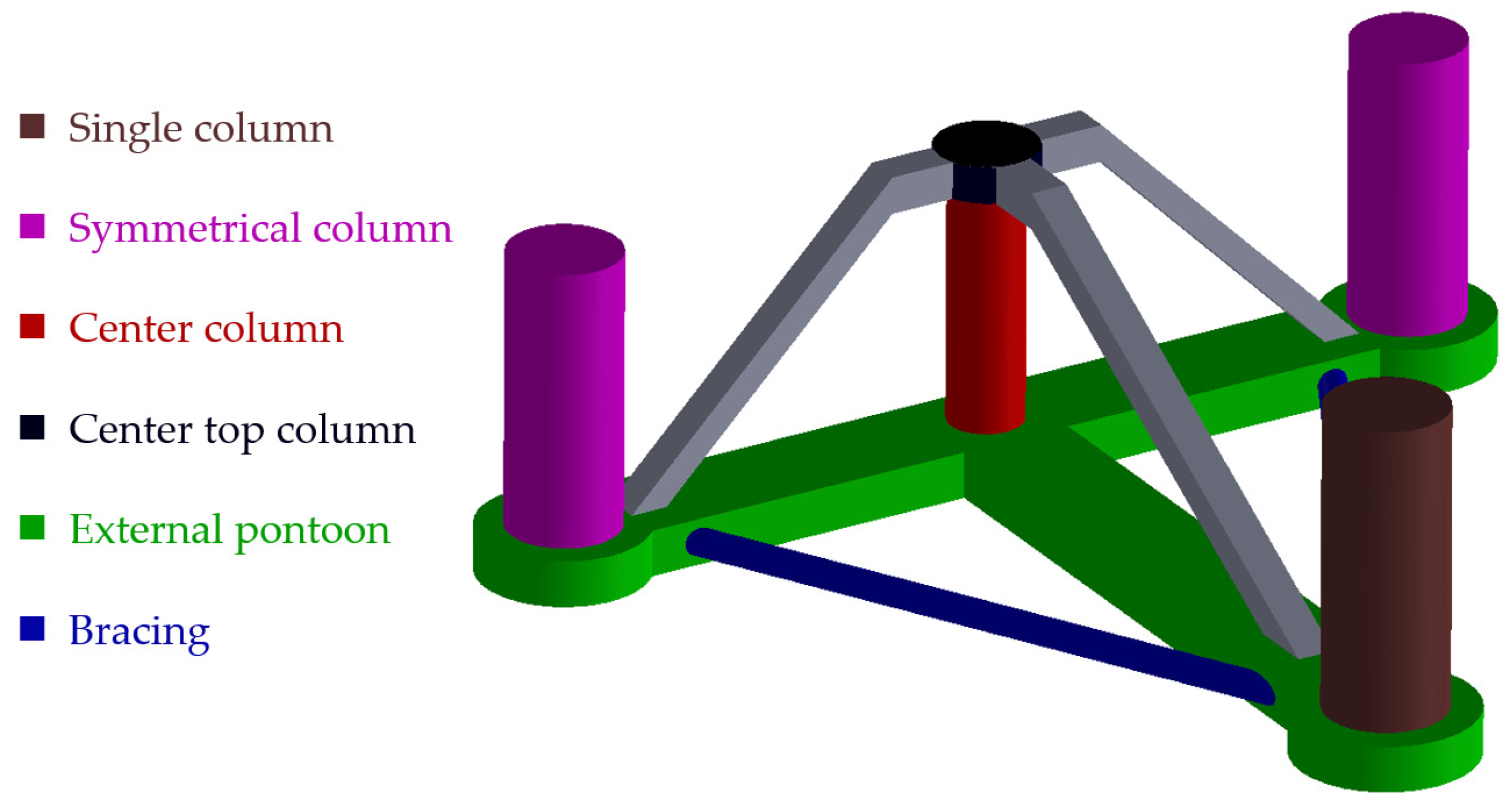
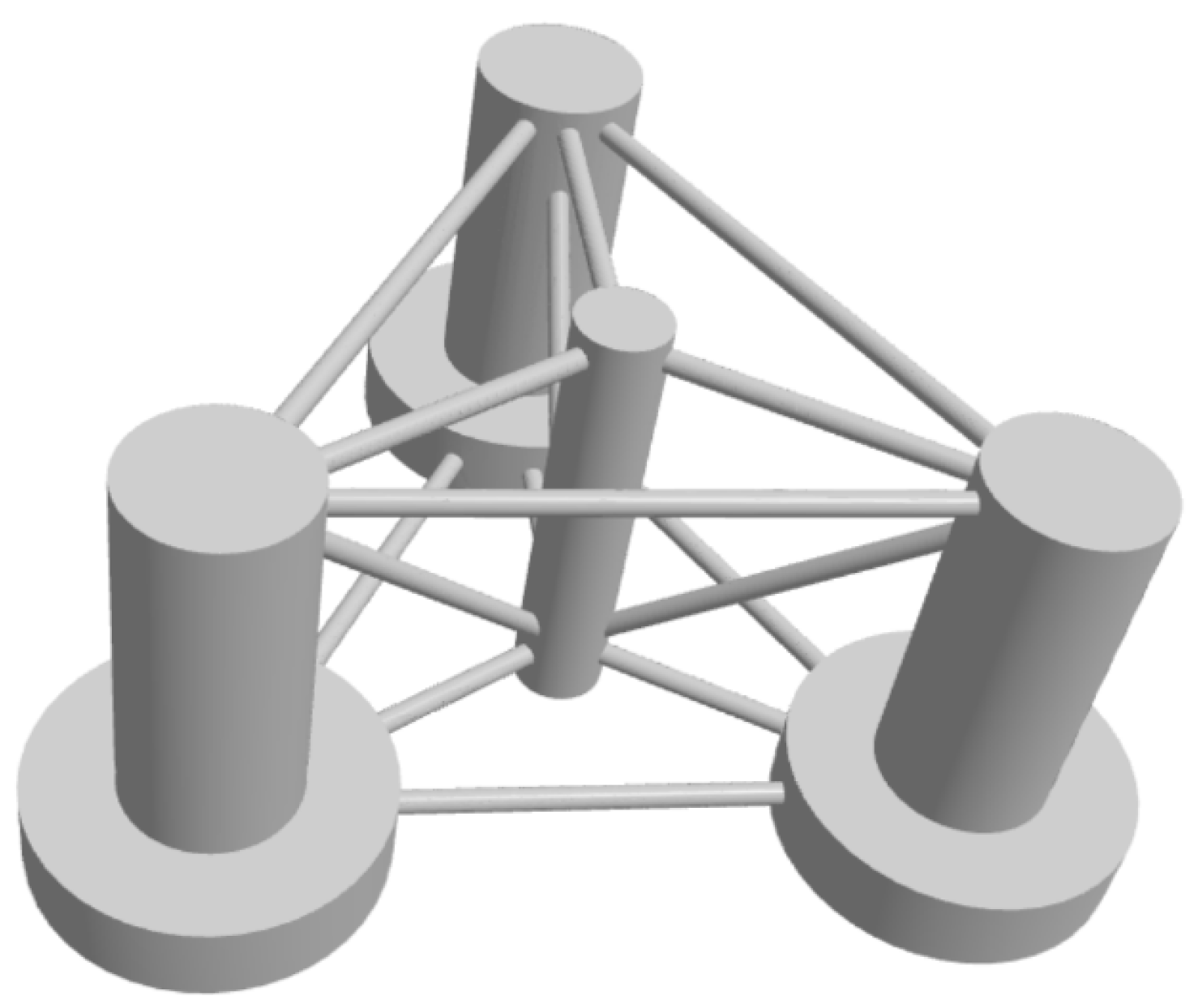
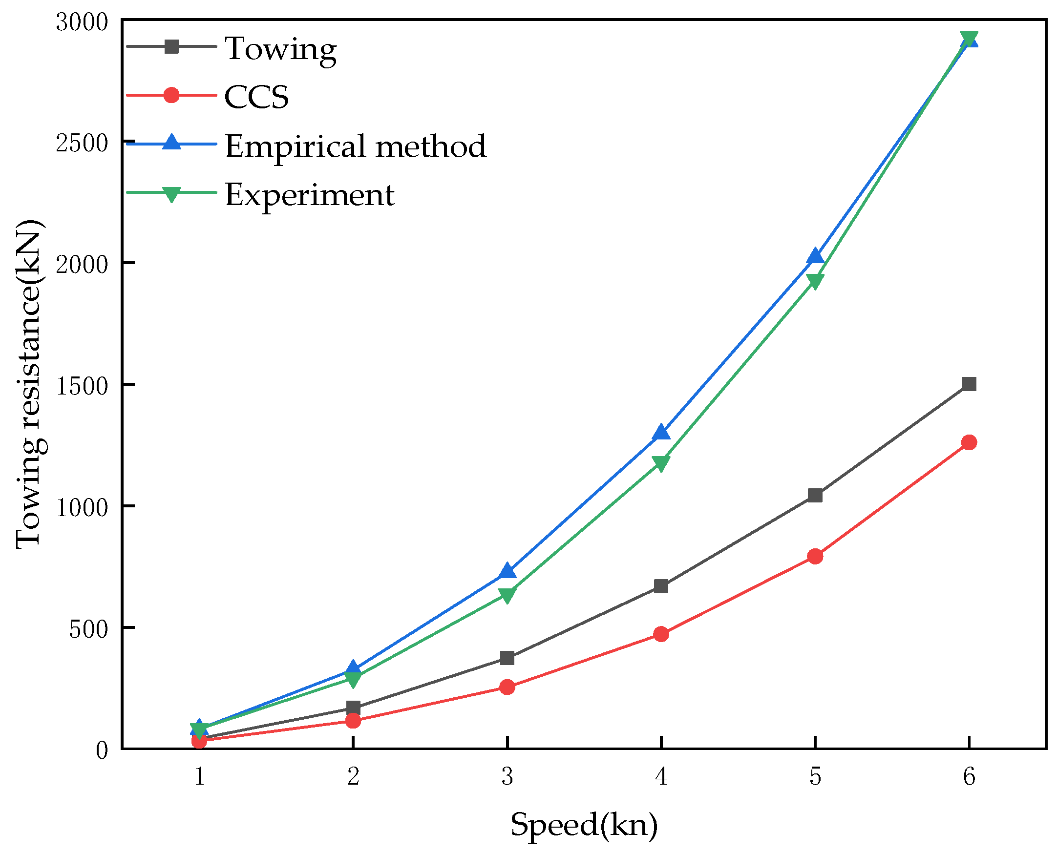
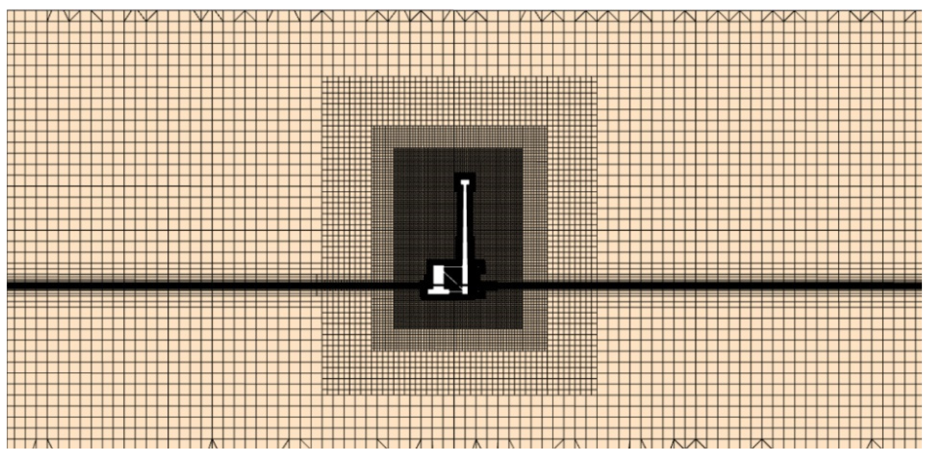
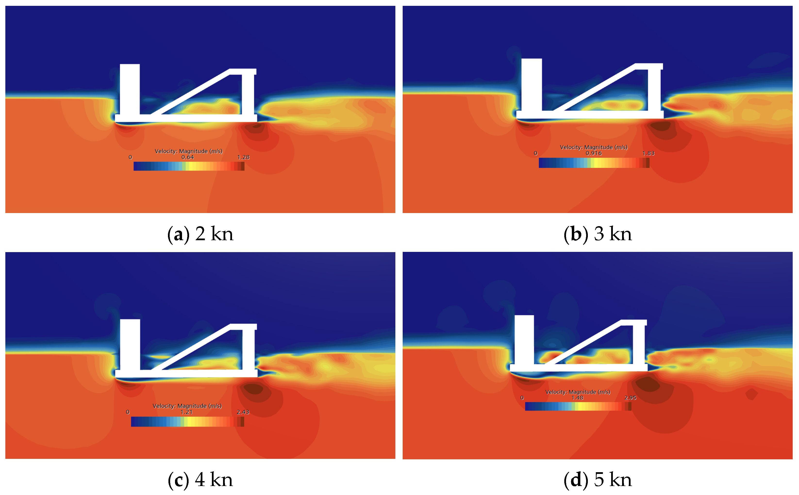
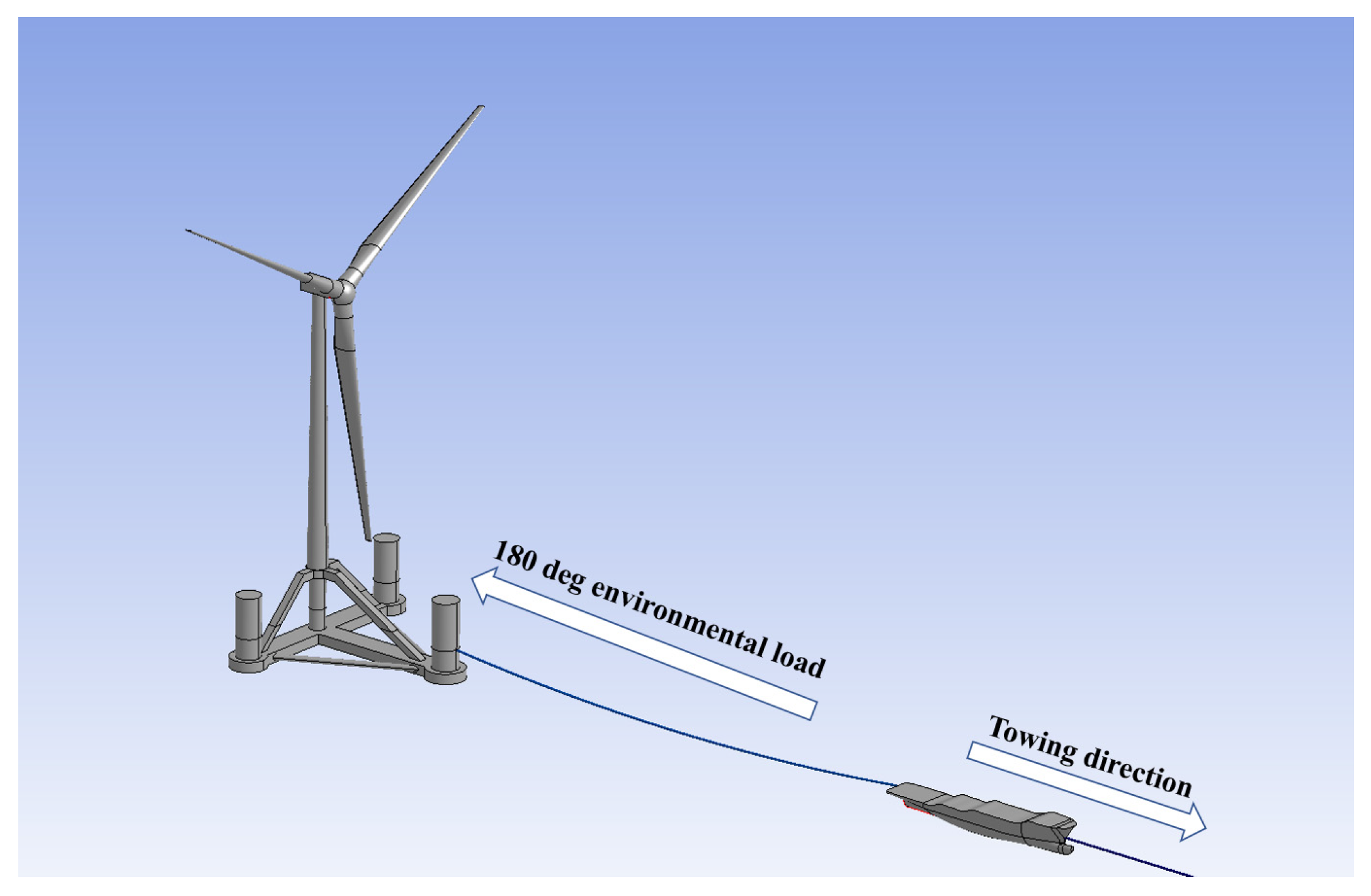
Based on the above work, this paper proposes a research method for towing resistance of floating wind turbines to achieve the purpose of quickly predicting tow resistance and guiding tug selection. First, the CFD method was used to study the towing resistance of the OC4 platform, and the accuracy of the CFD method was verified by comparison with experiments. Subsequently, the resistance of a new type of floating wind turbine platform in still water was analyzed, and different resistance calculation methods were combined to compare and analyze the resistance prediction results. The resistance prediction method used can predict the tow resistance more accurately. The integrated towing model of floating wind turbines was established by ANSYS-AQWA, and the influence of waves and wind on towing resistance was further analyzed.

2. Analysis Theory Foundation

2.1. Governing Equations

This paper studies the towing resistance of floating wind turbines using the CFD method. For three-dimensional continuous, unsteady, incompressible fluids, the fluid control equations include the continuity equation and the RANS (Navier-Stokes Equations, N-S) equations:
ρ t + x i ( ρ u i ) = 0 ,
t ( ρ u i ) + x i ( ρ u i u j ) = p x i + x i ( μ u i x j ρ u u j ¯ + ρ S i ) ,
where u i and u j are the components of the velocity vector u in the x i and x j directions; p is the pressure; μ is the fluid viscosity; ρ u u j ¯   is the Reynolds stress term; and S i is the fluid mass force.
The k ε turbulence model is used, which can solve the transport equations of turbulent kinetic energy k and turbulent dissipation rate ε . The turbulent kinetic energy k is:
t ( ρ k ) + x i ( ρ u i k ρ μ i P r k k x i ) = ρ ( P k + G b ε ) ,
The turbulent kinetic energy dissipation rate ε is
t ( ρ ε ) + x i ( ρ u i ε ρ μ i P r ε ε x i ) = ρ ε k ( C 1 P k + C 3 G b C 2 ε ) ,
where ρ is the density; P r k and P r ε are the Prandtl numbers corresponding to k and ε ; P k is the generation term of turbulent kinetic energy, caused by shear; G b is the volume generation rate of turbulent kinetic energy k caused by the change of gravity with density. C 1 , C 2 , and C 3 are model coefficients.

2.2. Empirical Formula for Towing Resistance

The empirical formula for calculating towing resistance in the China Classification Society (CCS) “GUIDELINES FOR TOWAGE AT SEA” [43] is mainly applicable to the hull:
R T = 1.5 ( R f + R B ) ,
where R f is the friction resistance of water; R B is the residual resistance of water.
The friction resistance and residual resistance are determined according to the following approximate method:
R f = 1.67 A 1 V 1.83 × 10 3 ,
R B = 0.147 δ A 2 V 1.74 + 0.15 V ,
where A 1 is the wet surface area; A 2 is the maximum cross-sectional area below the waterline of the towed float; δ is the square coefficient; and V is the towing speed. The square coefficient is an important parameter to describe the thickness of a ship’s underwater shape. It has no specific meaning for a special-shaped structure, such as a floating wind turbine. Therefore, for the sake of safety, the square coefficient in the empirical formula is taken as 1.0. Table 1 shows the shape coefficients of towed objects.
Among them, the buoy part is a cylinder with a shape coefficient of 0.5; the struts between the buoys are truss structures with an area shape coefficient of 1.3; the tower, nacelle, and blades are isolated structures, and the upper structures of the two types of wind turbines are exactly the same, with a shape coefficient of 1.5.
The book “Towing” (Oilfield Seamanship Series Volume 4) [44], published by OPL in the UK, defines the total resistance of towing a floating structure. In addition to the friction resistance R f and the residual resistance of water R B , the wind resistance R w is also considered:
R T = R f + R B + R w ,
The friction resistance, residual resistance, and wind resistance are calculated as follows:
R f = 3.522 A 1 F 1 V 2 × 10 3 ,
R B = 0.62 A 2 F 2 V 2 ,
R w = 0.611 ( V w + V ) 2 × C s A i × C H × 10 3 ,
The definitions of A 1 and A 2 are consistent with those in CCS specifications; F 1 is the fouling coefficient, the value of which is shown in Table 2; F 2 is the shape drag coefficient of the bow of the towed object; V w is the wind speed; C s and A i are the shape coefficient and the windward area, respectively; C H is the height coefficient of the geometric center of the windward area, the values of which are shown in Table 3.
The wet surface marine growth conditions during towing are slight marine growth and shellfish attachments, and the bottom fouling coefficient F 1 is 0.7; the floating wind turbine, as a special-shaped structure, does not have a bow, but its buoy is cylindrical, so the bow shape coefficient F 2 is 0.4; the centroid of the buoy and the struts between the buoys is between 0 and 15.3 m from the waterline, and its geometric center height coefficient C H is 1.0; the centroid of the upper isolated structure is between 76.0 and 91.5 m from the waterline, and its geometric center height coefficient C H is 1.43.
The estimation method of offshore drilling platform towing resistance [45] is a method summarized based on the characteristics of offshore drilling platforms and actual engineering experience. The resistance includes water friction resistance R f , waterfront pressure resistance R x , eddy resistance R c , and wind resistance R w :
R T = R f + R x + R c + R w ,
R f = 0.033 C f S v 1.825 ,
R x = 4.9 μ ω A 2 v 2 g ,
R c = 20 % R f ,
R w = 0.0098 K β v k 2 ( A L sin 2 θ + A T cos 2 θ ) ,
where C f is taken as 0.143; S is the waterline area; v is the ship speed; μ is taken as 0.8–1.0; ω is the seawater density; g is the acceleration of gravity; K is taken as 0.6; β is the air density; v k is the wind speed, and the ship speed is taken during still water towing; A L is the longitudinal projection area of the towed object above the waterline, A T is the transverse projection area of the towed object above the waterline; θ is the windward angle, which is taken as 45°.

3. Numerical Model and Method Validation

3.1. Computational Model

The floating wind turbine model used in this paper was designed by China Energy Engineering Group Guangdong Electric Power Design Institute Co., Ltd., Guangzhou, China [22]. The foundation of the floating wind turbine is a four-column semi-submersible platform. The projection of the center of the middle column of the three columns at the bottom is the origin of the coordinates, the direction from the center of the circle to the side column is the positive direction of the X-axis, the direction of the X-axis rotated 90° counterclockwise is the positive direction of the Y-axis, and the vertical upward is the positive direction of the Z-axis. The numerical calculation model established using STAR-CCM+ is shown in Figure 1, and the specific parameters of the model are shown in Table 4.

3.2. Numerical Pooling and Grid Independence Verification

A rectangular computational fluid domain is established around the floating wind turbine model, and the boundaries of the six faces are defined, as shown in Figure 2. In order to make the calculation results more accurate, the model adopts real-scale modeling, the right side, top, and bottom of the pool are set as velocity inlets, the left side is set as a pressure outlet, the two sides of the pool are also set as velocity inlets, and the surface of the wind turbine foundation is set as a no-slip wall.
The meshing of the numerical water pool directly affects the simulation accuracy and the computational time cost. Due to the complexity of the structure and movement of the floating wind turbine foundation on and below the water surface, a finer mesh is usually required near the wind turbine foundation; in the area of the water pool far away from the flow field propagation, the mesh size can be relatively large. The computational domain mesh adopts the cutting volume mesh. The standard k-ε turbulence model is robust in the fuselage boundary layer and the recirculation region, which is suitable for drag prediction [46]. The k-omega SST turbulence model and k-epsilon turbulence model are used to calculate the towing resistance of a ship with a draft of 12 m and a speed of 3 kn. The calculated results are 1193.94 kN and 1174.69 kN, respectively. The results show that the difference in the resistance calculation results is within 2%. Therefore, the k-ε turbulence model is selected as the turbulence model. The number of prism layers on the foundation surface of the floating wind turbine is 6, and the grid base size is 1.5 m. The grids near the wind turbine surface, the water surface, and the heave plate are coded. The final number of meshes is 3.048 million, the calculation time step is 0.03 s, and the total time is 180 s. The mesh scene is shown in Figure 3.
Prior to calculation, grid independence verification is mandatory. By altering the grid base size, the influence of the number of grids on the calculation results is eliminated. The verification process is undertaken with a draft of 12 m and a speed of 3 knots. The grid base size of 1.5 m is utilized as a foundation, with 0.3 m increments or decrements applied accordingly. This process leads to the selection of 1.2 m and 1.8 m as the grid base sizes, respectively, with the number of grids fixed at 2.489 million and 4.3 million for the verification process.
The calculation results are shown in Table 5. A comparison of the calculation results obtained from these three grids reveals that the impact of the varying numbers of grids on the resistance calculation results is not significant. Among them, the calculation result of the basic size of 1.2 m is the largest, and the calculation results of 1.5 m and 1.8 m are close. The maximum discrepancy among the three grids is 0.89%, which is within the acceptable range for engineering applications.

3.3. Method Validation

In order to verify the accuracy of the CFD method, it is necessary to compare the results of numerical simulations. The OC4 floating wind turbine platform is a 5 MW wind turbine designed by the United States [47]. This paper selects the OC4-DeepCwind floating wind turbine model for method verification, as shown in Figure 4. Ramachandran [7] obtained the resistance of the OC4 platform at a speed of 1–6 kn when towing in still water through model tests.
For the towing resistance of floating platforms, relevant specifications and standards of many countries and organizations in the world have formulated empirical formulas for towing resistance. However, as a new type of offshore renewable energy power generation platform, the towing resistance calculated by various empirical formulas for offshore floating wind turbines is quite different from the actual resistance. This paper calculates the still water towing resistance of the OC4 platform at speeds of 1–6 kn based on the fourth volume of “Towing” for oilfield ships published by OPL in the UK, the CCS “GUIDELINES FOR TOWAGE AT SEA” and the estimation method for towing resistance of offshore drilling platforms (hereinafter referred to as the “estimation method”), and the calculation results are compared with the model test results; see Table 6.
Figure 5 shows the resistance calculated using the empirical method compared with the test results. It is clear that the results obtained by the estimation method are closer to the test results. There is a significant difference between the calculated results of the fourth volume of Towing for Oilfield Marine Vessels published by OPL in the UK and the results of the Offshore Towing Guidelines of the China Classification Society, which is due to the fact that both are based on ship resistance calculations and are not applicable to the estimation of the towing resistance of a floating wind turbine. The offshore drilling platform towing resistance estimation method shows maximum error is 13.89% at 3 kn, and 0.71% at 6 kn. The offshore drilling platform method was not originally used for studying offshore floating wind turbines, and the CFD calculation results are large, so a greater margin is provided for tug selection. This method can be used for studying floating wind turbines and better predicting resistance.
The OC4 wind turbine platform was modeled and simulated to simulate the towing motion of the OC4 platform at a speed of 1–6 kn in still water, and the results were compared and analyzed with the results of the test and empirical formula estimation. Figure 6 shows the computational domain grid of the OC4 platform in the CFD software. The number of prism layers on the wind turbine surface is 15, the grid base size is 0.03 m, and the grids near the wind turbine and on the water surface are encrypted, and the final number of grids is 5.165 million.
The CFD calculation results are shown in Table 7. According to Figure 7, the calculation results of the CFD method are compared with the experimental data. When the speed is 1 kn, the maximum difference in the calculation results is 12.06%; as the speed increases, the difference in the calculation results gradually decreases, and when the speed reaches 6 kn, the error is 1.08%. Comparing the results of the CFD calculation and the results obtained by the estimation method, the maximum error is 18.6% at a speed of 3 kn, and the minimum error is 0.36% at a speed of 6 kn. According to the comparative analysis of the bar chart in Figure 7, the results calculated by the estimation method are larger than the test results, while the CFD calculation results are smaller than the test results. Moreover, the gap between the CFD calculation results and the experimental results at each speed is within a reasonable range.

4. Calculation Results and Towing Analysis

4.1. Hydrostatic Resistance Analysis

Towing resistance directly affects the efficiency, speed, and safety of towing. Using the CFD method, combined with the actual speed during towing, the single-column forward still water towing resistance of the new floating wind turbine at 9 m, 12 m, and 15 m drafts at 2 to 5 kn is simulated. Table 8 shows the calculation results of still water towing resistance at 2 to 5 kn at three different drafts. With the increase in draft and speed, the towing resistance will gradually increase. Figure 8 and Table 9 compare the CFD resistance calculation results and the estimation resistance calculation results of three different drafts at different speeds, as well as the percentage of error of the estimation method. It can be seen from the figure and table that the numerical simulation results are consistent with the empirical formula calculation results, but the error is slightly larger at higher speeds. However, the error is within 14% at all speeds. It is similar to the results verified by the method in Section 3.3.
The CFD-calculated velocity cloud diagram at 15 m draft and 2~5 kn speed is intercepted, as illustrated in Figure 9. As the speed increases, the difference in fluid velocity distribution before and after the floating wind turbine foundation increases significantly; the fluid velocity is observed to change significantly inside and around the floating wind turbine foundation, indicating that the fluid is separated when passing through the surface and inside of the wind turbine foundation, forming a low-speed area or reverse flow area. A vortex phenomenon is formed behind the foundation, especially near the rear of the foundation; there are obvious velocity fluctuations and eddies, which may lead to an increase in pressure resistance, thereby significantly increasing the towing resistance.

4.2. Tow Response and Drag Analysis

The integrated towing of floating wind turbines requires a reasonable tugboat configuration based on the size of the wind turbine, towing distance, sea conditions, etc., to ensure the efficiency and safety of the towing operation. The common towing formation configuration scheme is shown in Figure 10. According to the “Technical Requirements for Offshore Platform Towing” [48], the single tugboat layout should be given priority. When the provided tugboat power cannot meet the towing requirements and towing time, a double tugboat towing form should be adopted. The installation operation of China’s “Ming Yang Tian Cheng” adopted the towing method shown in Figure 10a, while the installation operation of WindFloat Atlantic adopted the towing method shown in Figure 10b.
Due to its unique structural configuration, this paper opts for the towing mode depicted in Figure 10a, employing the towing model developed by Chen et al. [33] to formulate a numerical model of the FOWT towing system in ANSYS-AQWA. This facilitates an investigation into the impact of waves and wind on the towing resistance of FOWT and its corresponding motion response, as illustrated in Figure 11. The parameters of the tow cable and mooring point are specified in Table 10.
The 15 m draft towing was selected as the object to study the influence of different speeds and environmental loads on the dynamic response and towing resistance of FOWT towing. Figure 12 shows the 6-DOF RAO values of FOWT under different incident waves. With the increase in speed, the peak values of the heave and pitch RAO of FOWT at 0°, 45°, and 90° increase significantly, but under other wave conditions, the peak values of the RAO of other degrees of freedom are not significantly affected.
Taking a 15-m draft as the research object, Figure 13 shows the drag of the cable on the FOWT when the towing model is towing in still water at a speed of 2 to 4 kn. The average towing resistance at different speeds is 594.5 kN at 2 kn, 1304.9 kN at 3 kn, and 2497.7 kN at 4 kn, which is basically consistent with the resistance results calculated by the CFD method. It is proven that the established numerical model can simulate the towing scenario.
As illustrated in Figure 11, wind and wave conditions are incorporated to assess the dynamic response of the established dynamic simulation model during towing. The selected wave type is JONSWAP, with a peak factor of 3.3, a significant wave height of 1 m, a peak period of 10 s, a wind speed of 11.4 m/s, and no additional flow velocity is added except for the towing speed. The motion history curve of the towing system is analyzed for the period from 2000 s to 2500 s. The towing force curve of the towline on the FOWT under wave conditions is illustrated in Figure 14. The mean towing force is observed to be relatively unchanged in comparison with that measured under calm water conditions; however, the towing force peaks are recorded at 845.66 kN, 1707.94 kN, and 2947.32 kN at speeds of 2, 3, and 4 knots, respectively. These figures indicate an increase of 42%, 30%, and 18%, respectively, when compared with the towing force measurements taken under calm water conditions. This finding suggests that waves have a significant impact on the extreme value of towing resistance, though this impact diminishes with increasing speed. In the context of tugboat selection, the extreme value of towing resistance primarily serves as a reference. The motion response of the towing system is illustrated in Figure 15, with the roll motion response being excluded [33]. As the speed increases, the amplitude of the heave and pitch motion response increases, which is consistent with the frequency domain analysis results. The average value of the pitch motion can be used as the tilt angle of the floating wind turbine during towing, which is used to evaluate the safety of wind turbine towing operations. It is observed that the tilt angles at different speeds are not significantly different, with an average value of approximately 1.84°.
According to the DNV’s [49] requirements for tugboat selection in the specifications for offshore operations, the total towing force of the tugboat should be sufficient to compensate for the effects of wind, waves, and currents and have sufficient surplus. Therefore, after considering the complex sea conditions during towing and the impact of the tow cable, a 30% towing force reduction is required. Taking the resistance at 3 kn and 4 kn as an example, after considering the towing reduction, the required tugboat towing force is 2439.9 kN and 4210.45 kN, respectively. Obviously, the towing resistance of FOWT at 15 m draft and 4 kn speed is too large, the requirements for tugboats are too high, and it is not suitable for towing operations. Taking the average increase of 20% in resistance under wind and wave conditions compared with resistance in still water as a reference, the towing resistance at different speeds with drafts of 9 m and 12 m is calculated and compared with that of a 15-m draft, as shown in Figure 16. Taking the existing engineering ship “Hai Yang Shi You 291” [50] as an example, the bollard pull is 361 tons, and the effective towing force after reduction is 2476.46 kN. According to the comparative analysis in Figure 16, the towing speed of 4 kn can meet the requirements only when the draft is 9 m, the speed of 3 kn meets the requirements at all drafts, and the speed of 5 kn cannot meet the requirements due to too large resistance.

5. Conclusions

This paper studies the towing resistance of a floating wind turbine and creates a numerical model of the towing system. The paper discusses calculation methods, including CFD, and the selection of towing schemes. STAR-CCM+ is used to model and calculate a large megawatt floating turbine, and the results are compared to verify the CFD method. A towing model was built in AQWA to verify the towing system and analyze the effects of waves and wind on the towing system’s response. The study draws several conclusions.
(1)
The towing resistance of a new type of semisubmersible wind turbine platform in still water was calculated using the CFD method and the estimation method. The error of the calculation result was within 14%, which proved the feasibility of using the estimation method to calculate the results of FOWT towing resistance. However, the estimation method cannot calculate the difference between the resistance of FOWT towing with a single column facing forward and double columns facing forward, while the CFD method can distinguish the different resistances when the FOWT is towed in different directions. Therefore, the CFD method and the estimation method can be combined to quickly predict the towing resistance and provide guidance for towing operations.
(2)
Towing resistance is closely related to the draft, displacement, and foundation configuration of the wind turbine platform. When meeting the towing resistance requirements of the floating wind turbine, the platform draft can be appropriately increased to improve towing stability.
(3)
The calculation results of time domain analysis show that the amplitude of the heave motion of FOWT at different towing speeds will increase with the increase in towing speed, but there is no obvious fluctuation. The pitch angle is kept at approximately 1.8°, which is within the safe towing range. The environmental load also has a great influence on the towing resistance, but the effect of this influence will decrease with the increase in speed.
(4)
When the new semisubmersible wind turbine model reaches a speed of 4 kn at a draft of 9 m, the resistance has reached 1900.51 kN. At this time, the requirements for tugboats are relatively high. In order to ensure the safety of towing and the convenience of towing schemes, the towing speed should be kept at 4 kn or below as much as possible, and multiple auxiliary tugboats should be used to coordinate the improvement of the stability of the towing system.
It must be noted that the main purpose of this paper is to study the prediction of FOWT towing resistance and the requirements for tugboat selection, so the analysis of the motion response of the towing system is not comprehensive. These issues may need further consideration and specific analysis of different issues in the towing system.

Author Contributions

P.G.: investigation, methodology, software, writing—original draft, funding acquisition. M.C.: investigation, methodology, software, data curation, writing—original draft. X.Y.: supervision, methodology, writing—review. S.L.: conceptualization, supervision, data curation, validation. W.L.: supervision, project administration, data curation. Z.W.: software, methodology, data curation, writing—original draft. Y.T.: software, writing—review and editing. X.J.: methodology, software, writing—review. All authors have read and agreed to the published version of the manuscript.

Funding

This research was supported by the National Natural Science Foundation of China, grant number 52171275.

Data Availability Statement

The original contributions presented in this study are included in the article.

Acknowledgments

This paper is based on the research on the key technologies of deep-sea floating wind power research project of China Energy Construction.

Conflicts of Interest

Authors Pengfei Gao, Xiaobin Yuan, Shihua Liu, and Wen Lin were employed by the company China Gezhouba Group Electric Power Co., Ltd. The remaining authors declare that the research was conducted in the absence of any commercial or financial relationships that could be construed as a potential conflict of interest.

References

  1. Council, G.W.E. Global offshore wind report 2020. GWEC Bruss. Belg. 2020, 19, 10–12. [Google Scholar]
  2. Ma, X.; Li, M.; Li, W.; Liu, Y. Overview of Offshore Wind Power Technologies. Sustainability 2025, 17, 596. [Google Scholar] [CrossRef]
  3. Wu, X.; Hu, Y.; Li, Y.; Yang, J.; Duan, L.; Wang, T.; Adcock, T.; Jiang, Z.; Gao, Z.; Lin, Z. Foundations of offshore wind turbines: A review. Renew. Sustain. Energy Rev. 2019, 104, 379–393. [Google Scholar] [CrossRef]
  4. Jiang, Z. Installation of offshore wind turbines: A technical review. Renew. Sustain. Energy Rev. 2021, 139, 110576. [Google Scholar] [CrossRef]
  5. Ren, Z.; Verma, A.S.; Li, Y.; Teuwen, J.J.; Jiang, Z. Offshore wind turbine operations and maintenance: A state-of-the-art review. Renew. Sustain. Energy Rev. 2021, 144, 110886. [Google Scholar] [CrossRef]
  6. Hu, M.; Shi, J.; Yang, S.; Chen, M.; Tang, Y.; Liu, S. Current Status and Future Trends in Installation, Operation and Maintenance of Offshore Floating Wind Turbines. J. Mar. Sci. Eng. 2024, 12, 2155. [Google Scholar] [CrossRef]
  7. Ramachandran, R.C.; Serraris, J.-J.; Montfort, J.H.; De Ridder, E.-J.; Desmond, C.; Murphy, J. Towing Analysis and Validation of a Fully Assembled Floating Offshore Wind Turbine Based on an Experimental Study. J. Mar. Sci. Eng. 2024, 12, 689. [Google Scholar] [CrossRef]
  8. Kim, Y.J.; Charlou, M.; Bouscasse, B.; Leroy, V.; Aliyar, S.; Bonnefoy, F.; Kim, K.-H.; Choi, Y.-M. High fidelity simulations of a floating offshore wind turbine in irregular waves by coupling OpenFOAM and OpenFAST. Renew. Energy 2025, 243, 122486. [Google Scholar] [CrossRef]
  9. Ishihara, T.; Phuc, P.V.; Sukegawa, H.; Shimada, K.; Ohyama, T. A Study on the Dynamic Response of a Semi-Submersible Floating Offshore Wind Turbine System Part 1: A Water Tank Test. In Proceedings of the 12th International Conference on Wind Engineering, Australasian Wind Engineering Society Gairns, Cairns, Australia, July 2007; pp. 2511–2518. [Google Scholar]
  10. Luan, C.; Gao, Z.; Moan, T. Design and Analysis of a Braceless Steel 5-mw Semi-Submersible Wind Turbine. In Proceedings of the International Conference on Offshore Mechanics and Arctic Engineering, Busan, South Korea, 19–24 June 2016; p. V006T009A052. [Google Scholar]
  11. Ma, C.; Zhang, T.; Jiang, Z.; Ren, Z. Dynamic analysis of lowering operations during floating offshore wind turbine assembly mating. Renew. Energy 2025, 243, 122528. [Google Scholar] [CrossRef]
  12. Jonkman, J.M. Dynamics of offshore floating wind turbines—Model development and verification. Wind Energy Int. J. Prog. Appl. Wind Power Convers. Technol. 2009, 12, 459–492. [Google Scholar] [CrossRef]
  13. Zhao, G.; Dong, S. Comparison of Different Iform-Based Methods for the Long-Term Extreme Response Estimation of a Floating Offshore Wind Turbine. Available online: https://papers.ssrn.com/sol3/papers.cfm?abstract_id=5106173 (accessed on 13 April 2025).
  14. Shanahan, T.; Fitzgerald, B. Wind–Wave Misalignment in Irish Waters and Its Impact on Floating Offshore Wind Turbines. Energies 2025, 18, 372. [Google Scholar] [CrossRef]
  15. Lotfizadeh, O.; Barahmand, Z.; Amlashi, H. Life Cycle Assessment of Floating Offshore Wind Farms: The Case of Hywind Tampen in Norway. Scand. Simul. Soc. 2025, 33–40. [Google Scholar] [CrossRef]
  16. Barile, D.A.; Sosa, R.; Aubrun, S.; Otero, A.D. Novel CFD approach for simulation of an ABL wind tunnel flow: Validation and application to a FOWT model. Wind Energy Sci. Discuss. 2025, 2025, 1–20. [Google Scholar]
  17. Zhao, H.; Wu, X.; Zhou, Z. Exploring motion stability of a novel semi-submersible platform for offshore wind turbines. Energies 2024, 17, 2313. [Google Scholar] [CrossRef]
  18. Ronold, K.O.; Landet, E.; Jørgensen, E.R.; Sandberg, J. Design Standards for Floating Wind Turbine Structures. In Proceedings of the European Wind Energy Conference, Brussels, Belgium, 16 March 2011; pp. 14–17. [Google Scholar]
  19. Sun, Y.-C.; Yang, R.-Y. Design and Numerical Investigation on Octagonal Barge-Type FOWT with Counterweight Suspension System. Energies 2025, 18, 264. [Google Scholar] [CrossRef]
  20. Belvasi, N.; Desmond, C.; Murphy, J. Calibrating hydrodynamic viscous damping in engineering models of floating wind platform utilising simplified CFD models. J. Mar. Eng. Technol. 2025, 1–14. [Google Scholar] [CrossRef]
  21. Yang, Y.; Liu, S.; Guo, X.; Chen, W.; Tao, T.; Wu, H.; Wang, K. The Mooring Optimization and Hydrodynamic Characteristics of the Combined Concept of a 15 MW FOWT with WECs. J. Mar. Sci. Eng. 2025, 13, 545. [Google Scholar] [CrossRef]
  22. Huang, J.; Xu, H.; Chen, L.; Lin, K.; Guo, M.; Yang, M.; Rui, S. Analysis of mooring performance and layout parameters of multi-segment mooring system for a 15 MW floating wind turbine. Front. Energy Res. 2024, 12, 1502684. [Google Scholar] [CrossRef]
  23. Jiang, Y.; Duan, Y.; Li, J.; Chen, M.; Zhang, X. Optimization of mooring systems for a 10MW semisubmersible offshore wind turbines based on neural network. Ocean Eng. 2024, 296, 117020. [Google Scholar] [CrossRef]
  24. Tian, H.; Soltani, M.N.; Yeter, B.; Galván-Pozos, D.E. Design of a novel tower damping system for semi-submersible floating offshore wind turbines considering fatigue and ultimate limit states. Ocean Eng. 2025, 320, 120343. [Google Scholar] [CrossRef]
  25. Zou, M.; Chen, M.; Zhu, L.; Li, L.; Zhao, W. A constant parameter time domain model for dynamic modelling of multi-body system with strong hydrodynamic interactions. Ocean Eng. 2023, 268, 113376. [Google Scholar] [CrossRef]
  26. Chen, M.; Ouyang, M.; Li, T.; Zou, M.; Ye, J.; Tian, X. Numerical modelling of a catamaran float-over deck installation for a spar platform with complex hydrodynamic interactions and mechanical couplings. Ocean Eng. 2023, 287, 115905. [Google Scholar] [CrossRef]
  27. McMorland, J.; Collu, M.; McMillan, D.; Carroll, J. Operation and maintenance for floating wind turbines: A review. Renew. Sustain. Energy Rev. 2022, 163, 112499. [Google Scholar] [CrossRef]
  28. Centeno-Telleria, M.; Yue, H.; Carrol, J.; Penalba, M.; Aizpurua, J.I. Assessing heavy maintenance alternatives for floating offshore wind farms: Towing vs. onsite replacement strategies. Appl. Energy 2025, 377, 124437. [Google Scholar] [CrossRef]
  29. Chen, M.; Huang, W.; Liu, H.; Hallak, T.S.; Liu, S.; Yang, Y.; Tao, T.; Jiang, Y. A novel SPM wind-wave-aquaculture system: Concept design and fully coupled dynamic analysis. Ocean Eng. 2025, 315, 119798. [Google Scholar] [CrossRef]
  30. Zhang, X.; Li, B.; Hu, Z.; Deng, J.; Xiao, P.; Chen, M. Research on size optimization of wave energy converters based on a floating wind-wave combined power generation platform. Energies 2022, 15, 8681. [Google Scholar] [CrossRef]
  31. Collu, M.; Maggi, A.; Gualeni, P.; Rizzo, C.M.; Brennan, F. Stability requirements for floating offshore wind turbine (FOWT) during assembly and temporary phases: Overview and application. Ocean Eng. 2014, 84, 164–175. [Google Scholar] [CrossRef]
  32. Berg, P.W.S. A Discussion of Technical Challenges and Operational Limits for Towing Operations; NTNU: Taipei, Taiwan, 2017. [Google Scholar]
  33. Chen, M.; Chen, Y.; Li, T.; Tang, Y.; Ye, J.; Zhou, H.; Ouyang, M.; Zhang, X.; Shi, W.; Sun, X. Analysis of the wet-towing operation of a semi-submersible floating wind turbine using a single tugboat. Ocean Eng. 2024, 299, 117354. [Google Scholar] [CrossRef]
  34. Hyland, T.; Adam, F.; Dahlias, F.; Großmann, J. Towing tests with the GICON®-TLP for wind turbines. In Proceedings of the ISOPE International Ocean and Polar Engineering Conference, Busan, Republic of Korea, 15–20 June 2014; p. ISOPE–I-14-065. [Google Scholar]
  35. Ding, H.; Hu, R.; Le, C.; Zhang, P. Towing operation methods of offshore integrated meteorological mast for offshore wind farms. J. Mar. Sci. Eng. 2019, 7, 100. [Google Scholar] [CrossRef]
  36. Ding, H.-Y.; Feng, Z.-T.; Zhang, P.-Y.; Le, C.-H. Integrated towing transportation technique for offshore wind turbine with composite bucket foundation. China Ocean Eng. 2022, 36, 133–143. [Google Scholar] [CrossRef]
  37. Le, C.; Ren, J.; Wang, K.; Zhang, P.; Ding, H. Towing performance of the submerged floating offshore wind turbine under different wave conditions. J. Mar. Sci. Eng. 2021, 9, 633. [Google Scholar] [CrossRef]
  38. Guo, C.; Zhong, X.; Zhao, D. Research on Scale Effect of Resistance Components for Full-Formed Ship Based on Large-Scale Model Towing Test. J. Mar. Sci. Eng. 2023, 11, 1300. [Google Scholar] [CrossRef]
  39. Jayachandran Nair, R. Towing of Floating Wind Turbine Systems; UiT The Arctic University of Norway: Tromsø, Noorwegen, 2020. [Google Scholar]
  40. Qi, K.; Zhang, J.; Zhang, L.; Zhang, J.; Gan, R. A Review of Research Progress on Cables and Towed Objects of the Ocean Engineering Towing System. J. Mar. Sci. Eng. 2025, 13, 257. [Google Scholar] [CrossRef]
  41. Zhang, D.; Zhao, B.; Zhu, K.; Jiang, H. Dynamic response of deep-Sea trawl system during towing process. J. Mar. Sci. Eng. 2023, 11, 145. [Google Scholar] [CrossRef]
  42. Hope, M.M. Offshore Towing of Floating Wind Turbines Design Aspects with Focus on Numerical Modelling; NTNU: Taipei, Taiwan, 2021. [Google Scholar]
  43. China Classification Society. Guidelines for Towage at Sea; China Classification Society: Beijing, China, 2012. [Google Scholar]
  44. Hancox, M. Towing (Oilfield Seamanship Series Volume 4); Witherbys: Scotland, UK, 1997. [Google Scholar]
  45. Li, Y. Research into choice of main tug boat for drilling rig towing. China Offshore Oil Gas 1995, 7, 20–26. [Google Scholar]
  46. Sarker, D.K.; Tarafder, M.S. Numerical analysis of fluid flow around ship hulls using STAR-CCM+ with verification results. J. Mar. Sci. Appl. 2024, 23, 276–291. [Google Scholar] [CrossRef]
  47. Robertson, A.; Jonkman, J.; Masciola, M.; Song, H.; Goupee, A.; Coulling, A.; Luan, C. Definition of the Semisubmersible Floating System for Phase II of OC4; National Renewable Energy Lab.(NREL): Golden, CO, USA, 2014. [Google Scholar]
  48. Ministry of Transport of the People’s Republic of China. Technical Requirements for Offshore Platforms Towing; Ministry of Transport of the People’s Republic of China: Beijing, China, 2020. [Google Scholar]
  49. DNVGL-ST-N001; Marine Operations and Marine Warranty. Norway. 2020.
  50. Offshore Oil Engineering Co., Ltd. Deepwater Multifunctional Operation Vessel Equipment. Available online: https://www.cnoocengineering.com/zbss/ssdgnzycbzb/202405/t20240521_14858.html (accessed on 9 March 2025).
Figure 1. Floating wind turbine basic model.
Jmse 13 00789 g001
Figure 2. Numerical pool.
Jmse 13 00789 g002
Figure 3. Meshing.
Figure 3. Meshing.
Jmse 13 00789 g003
Figure 4. OC4-DeepCwind Model.
Jmse 13 00789 g004
Figure 5. Comparison of wind turbine drag results using different calculation methods.
Jmse 13 00789 g005
Figure 6. OC4 platform resistance calculation grid model.
Jmse 13 00789 g006
Figure 7. Comparison of towing resistance results.
Jmse 13 00789 g007
Figure 8. Comparison of towing resistance at different drafts and speeds.
Jmse 13 00789 g008
Figure 9. CFD velocity cloud map.
Jmse 13 00789 g009
Figure 10. Common towing methods for floating wind turbines.
Jmse 13 00789 g010
Figure 11. Numerical model of the FOWT towing system in AQWA.
Jmse 13 00789 g011
Figure 12. RAOs of the FOWT.
Jmse 13 00789 g012aJmse 13 00789 g012b
Figure 13. Cable drags in still water.
Jmse 13 00789 g013
Figure 14. Towline tension at different speeds in wave and wind conditions.
Jmse 13 00789 g014
Figure 15. Motion response of FOWT at different towing speeds.
Jmse 13 00789 g015
Figure 16. Comparison of different draft resistance of new floating wind turbines.
Jmse 13 00789 g016
Table 1. Towed object shape coefficient.
ShapeShape Coefficient
Spherical0.4
Cylindrical0.5
Large flat surfaces (hull, deckhouse, smooth underdeck area)1.0
Groups of deckhouses or similar structures1.1
Drilling rig1.25
Wire Rope1.2
Exposed beams and girders below deck1.3
Widgets1.4
Isolated structural shapes (cranes, beams, etc.)1.5
Table 2. Towed object fouling coefficient.
Condition of Marine Life on the Wet Surface of the Towed ObjectFouling Coefficient
Clean surface, no attachment0.3
Surface cleaning, sticky substances0.4
Slight marine life on the surface0.5
Minor marine growth/small shellfish0.6
Slight marine growth/shell deposits0.7
Moderate amount of marine growth/shellfish0.8
Large amounts of marine life/shell deposits/obvious convex surfaces0.9
Table 3. Height coefficient of geometric center of windward area.
Height of Geometric Center from Waterline (m)Height Coefficient
0–15.31.00
15.3–30.51.10
30.5–46.01.20
46.0–61.01.30
61.0–76.01.37
76.0–91.51.43
91.5–106.51.48
Table 4. Basic parameters of the floating wind turbine.
Designation, Parameter (Unit)Value
Molded breadth, B (m)115.6
Molded length, L (m)96.3
Single column diameter, D (m)13
Symmetrical column diameter, D (m)12
Center column diameter, D (m)8
Center column diameter, D (m)11
External pontoon height, H (m)5
Bracing diameter, D (m)3
Table 5. Comparison of grid verification results.
Grid Base Size (m)Grid Quantity (Million)Resistance Results (kN)
1.24.31182.10
1.53.0481171.66
1.82.4891174.69
Table 6. Resistance calculation results.
Speed (kn)Towing (kN)CCS (kN)Estimation Method (kN)Experiment (kN) [7]
141.5632.3681.1981.7
2166.88114.81325.02290
3373.06252.95725.51637
4667.54470.981296.601180
51041.41791.472021.241930
61499.831260.302909.112930
Table 7. OC4 platform resistance results calculated by the CFD method.
Speed (kn)Towing Resistance (kN)
171.84
2265.71
3590.45
41118.89
51888.29
62898.44
Table 8. Results of towing resistance at different drafts calculated by CFD.
Speed (kn)9 m Draft Resistance (kN)12 m Draft Resistance (kN)15 m Draft Resistance (kN)
2468.17529.03591.62
31016.901171.661303.39
41900.512212.352496.86
52908.353452.324043.86
Table 9. Estimation and CFD calculation error percentage.
Speed (kn)9 m Percent Error (%)12 m Percent Error (%)15 m Percent Error (%)
211.207.564.94
38.656.733.58
411.8611.529.96
510.9511.7413.35
Table 10. Parameters of towing cables and mooring points.
ItemValue
Mass of unit length (kg/m)47.89
Equivalent diameter (m)0.088
Stiffness of towing cable (kN)3.13 × 10⁵
Breaking force (kN)4.9 × 10³
Cable length (m)266
FOWT mooring point coordinates (m)(84, 0, 0)
Tugboat mooring point coordinates (m)(350, 0, 0)
Disclaimer/Publisher’s Note: The statements, opinions and data contained in all publications are solely those of the individual author(s) and contributor(s) and not of MDPI and/or the editor(s). MDPI and/or the editor(s) disclaim responsibility for any injury to people or property resulting from any ideas, methods, instructions or products referred to in the content.

