Article

A Method for Dynamic Response Analysis of Offshore Substation Platform Foundations Based on Modal Truncation

1
Power China Huadong Engineering Corporation Limited, Hangzhou 311122, China
2
College of Marine Science and Technology, China University of Geosciences, Wuhan 430074, China
3
School of Civil Engineering & Transportation, South China University of Technology, Guangzhou 510641, China
4
Shenzhen Research Institute, China University of Geosciences, Shenzhen 518057, China
*
Author to whom correspondence should be addressed.
J. Mar. Sci. Eng. 2025, 13(4), 750; https://doi.org/10.3390/jmse13040750
Submission received: 10 March 2025 / Revised: 3 April 2025 / Accepted: 7 April 2025 / Published: 9 April 2025
(This article belongs to the Section Ocean Engineering)

Abstract

:
The foundation structure of offshore substation platforms is complex and has numerous degrees of freedom. The computational efficiency of dynamic response analysis using traditional time-domain methods is often relatively low. To facilitate the dynamic response analysis of offshore substation platform foundation structures with large degrees of freedom (DOFs), this paper proposes a method for dynamic response analysis based on modal truncation, which involves conducting a modal analysis and decoupling the vibration system matrix based on the modal shapes. Additionally, it analyzes the external load spectrum and determines the modal-truncation range through the transfer relationship between the external load frequency and the modal response. This approach reduces the size of the dynamic response analysis matrix, thereby significantly improving the computational efficiency of the dynamic response analysis of large-DOF offshore substation platform foundations. A six-DOF mass-damping-spring system and a finite element model of an offshore substation platform foundation were used to test the proposed method. The proposed method reduces the number of decoupled equations used to analyze the offshore substation platform foundation from 312 to 9. It was compared with the Newmark-β method, and the results show that the proposed method aligns well with the Newmark-β method in terms of calculation results, with computational efficiency improved by approximately 100 times.

1. Introduction

With the rapid development of the offshore wind-power industry, wind farms are expanding into deeper waters, which necessitates the construction of substations in more challenging deep-sea environments [1,2]. Because of their reliability and cost-effectiveness, jacket-type foundations are extensively utilized across diverse marine environments with varying water depths and geological conditions. They are ingeniously designed with piles and interconnected tubular members, which form a robust framework [3,4,5]. This framework is specifically engineered to bear the weight of offshore substations and withstand harsh marine environmental forces, making them suitable for sea areas with variable water depths and geologies.
As offshore substation platforms are a critical component of wind farms [6], their structural safety is essential to ensuring the stability and reliability of the entire offshore wind-power system [7]. The foundation of an offshore substation platform withstands the gravity load of the upper module and environmental loads. The high center of gravity of the upper module makes the foundation structure more sensitive to horizontal loads [8]. Additionally, structural vibrations caused by wind, waves, and currents during service may negatively impact the precision instruments installed on the platform [9]. Therefore, conducting dynamic response analysis of the offshore substation foundation structure during both the design and service phases is crucial for assessing structural safety and reliability and ensuring the safe operation of offshore substation platforms.
The dynamic response of offshore substation platform foundations is typically described using vibration differential equations. Analytical methods for solving these equations are generally classified into time-domain and frequency-domain approaches. Due to the complexity of the external loads acting on offshore substation platform foundations, it is often impossible to obtain an analytical solution for the dynamic response. The time-domain methods solve the vibration differential equation through numerical integration, enabling the analysis of both transient and steady-state responses. Because of the versatility of time-domain methods, they are widely applied in the field of dynamic response analysis. Klose et al. [10] employed the time-domain method to study the dynamic response of jacket-type offshore wind structures under wave forces and analyzed structural fatigue damage based on response-time histories. Clough [11] systematically introduced numerical methods for structural dynamic response calculations, including the Runge−Kutta, Newmark-β, and Wilson-θ methods, and analyzed their stability. Bishop et al. [12] utilized modal analysis techniques for research on fluid−structure interactions and developed a theoretical framework for calculating the vibration responses of offshore structures. Jin et al. [13] analyzed the dynamic response of fixed platforms under wave excitation using both numerical and analytical methods. Karademia [14] investigated the dynamic response of jacket platforms subjected to combined earthquake and wave loads using a time-domain approach.
Despite those advantages, time-domain methods face some computational challenges, particularly for systems with many degrees of freedom [15]. The computational load increases with the matrix size of the equation governing vibration, which means that using time-domain methods to calculate dynamic responses for offshore engineering structures with many degrees of freedom often results in low computational efficiency [16]. The essence of the time-domain method lies in time integration, where computational accuracy depends on the time step size, and convergence and stability issues may arise.
Conversely, the frequency-domain method, based on Fourier transform, solves vibration differential equations in the frequency domain, offering higher computational efficiency. However, traditional Fourier-based approaches are limited to capturing steady-state responses and cannot handle transient analysis due to the inherent assumptions of the Fourier transform. Researchers have proposed various methods to address these limitations. Veletsos and Ventura [17,18] proposed an approach to evaluate the transient response of classical damped linear systems based on steady-state response and extended it to non-classical damping systems involving soil−structure interactions. Mansur et al. [19,20] introduced the pseudo-force concept, which was derived from the initial conditions of the vibration system, to achieve transient response analysis in the frequency domain, and their results showed good agreement with those obtained using the Newmark-β method. Lee et al. [21] proposed a frequency-domain method based on Fourier transform for transient response analysis and validated its efficiency and accuracy by comparing it with time-domain calculations. Liu et al. [22] used Prony decomposition to obtain the poles and residues of external loads, incorporated initial conditions through Laplace transform, and established a relationship between Laplace and Fourier transforms to develop a frequency-domain method for transient response analysis. While improvements to Fourier-based frequency-domain methods help overcome their limitation of analyzing only steady-state responses, issues such as periodicity assumptions, energy leakage, and spectral leakage remain unavoidable.
To overcome these limitations, this paper presents a novel method for dynamic response analysis of offshore substation foundations based on modal truncation and frequency spectral analysis. The proposed approach first decouples the system’s vibration matrix using mode shapes, then establishes a transfer relationship between external load frequencies and modal responses through spectral analysis. Modes with negligible contributions outside the load frequency range are truncated, significantly reducing the number of equations to be solved. The dynamic response is reconstructed by mapping the modal responses back to physical space, achieving a balance between computational efficiency and analytical accuracy. A six-DOF mass-damping-spring system and a finite element model of an offshore substation foundation were applied to validate the method.
This study provides a practical and efficient solution for dynamic response analysis of offshore substation foundations, offering valuable insights for structural design optimization, safety assessment, and the long-term operational stability of offshore substation platforms in deep-sea environments. The findings contribute to advancing offshore wind-power infrastructure, which can be used to support the industry’s transition to deeper waters and harsher marine conditions.

2. Materials and Methods

2.1. Nemark-β Method

Under excitation from external loads such as wind, waves and currents, the vibration behavior of jacket-type offshore substation platform structure can be described by the following equation [16]:
M x ¨ ( t ) + C x ˙ ( t ) + K x ( t ) = f ( t )
where M , C and K are the mass matrix, damping matrix, and stiffness matrix of the offshore substation platform structure; x ( t ) , x ˙ ( t ) , and x ¨ ( t ) are the displacement, velocity, and acceleration; and f ( t ) is the external force acting on the structure.
Equation (1) is a second-order differential equation with constant coefficients for a multi-degree-of-freedom (MDOF) system. The exciting forces acting on offshore substation platforms are usually complex, which means that an analytical solution to Equation (1) is difficult to obtain. Therefore, numerical methods such as the Newmark-β method, Wilson-θ method, and Runge−Kutta method are commonly used to solve the equation.
Benefitting from the advantage of unconditional stability, the Newmark-β method is commonly employed to analyze the dynamic response of MDOF systems. In this paper, the Newmark-β method is introduced as the benchmark for comparison. For the moment of t = k Δ t , the offshore substation platform structure satisfies the equilibrium equation as follows:
M x ¨ k + C x ˙ k + K x k = f k
where x k , x ˙ k , x ¨ k , and f k are the displacement, velocity, acceleration, and external force vectors at time t = k Δ t ; k is the time step index; and Δ t is the integration time step.
Based on the recurrence formulas of the average acceleration method and the linear acceleration method, the velocity and acceleration update equations in the Newmark-β method are given by [23], as follows:
x ˙ k + 1 = α β Δ t x k + 1 α β Δ t x k + ( 1 α β ) x ˙ k + [ ( 1 α 2 β ) Δ t ] x ¨ k
x ¨ k + 1 = 1 β ( Δ t ) 2 x k + 1 1 β ( Δ t ) 2 x k 1 β Δ t x ˙ k ( 1 2 β 1 ) x ¨ k
where α and β are the parameters of the Newmark-β method.
Substituting Equations (3) and (4) into Equation (2), the displacement update equation in the Newmark-β method is obtained as follows [23]:
k ¯ x k + 1 = F ¯ k + 1
in which
k ¯ = M 1 β ( Δ t ) 2 + C α β Δ t + K
F ¯ k + 1 = f k + 1 + [ M 1 β ( Δ t ) 2 + C α β Δ t ] x k + [ M 1 β Δ t + C ( α β 1 ) ] x ˙ k + [ M ( 1 2 β 1 ) + C ( α 2 β 1 ) Δ t ] x ¨ k
Equations (3)–(5) represent the time-increment formulation of the Newmark-β method, which allows for the computation of displacement, velocity, and acceleration at subsequent time steps based on the initial displacement, velocity, and external load. Through the iterative application of this method, the dynamic response of jacket-type offshore substation platform structures can be calculated numerically.

2.2. Vibration Equation Decoupling and Modal Truncation

2.2.1. Decoupling of the Equation Governing Equation Governing Vibration

Due to the presence of damping, energy dissipation occurs when offshore structures vibrate, and the Rayleigh damping model is commonly used to represent the damping of the structure’s vibration. Based on the Rayleigh damping, the damping matrix of a jacket-type offshore substation platform can be expressed as follows [24]:
C = a M + b K
where a and b are the Rayleigh damping coefficients.
To decouple the equation governing the vibration of a jacket-type offshore substation platform, the modal space coordinate is introduced, and the relationship of physical and modal space coordinate can be expressed using x ( t ) = Φ u ( t ) . Substituting the relationship into Equation (1), the following formula can be obtained:
M Φ u ¨ ( t ) + C Φ u ˙ ( t ) + K Φ u ( t ) = f ( t )
where Φ is the modal shape matrix and u ( t ) , u ˙ ( t ) , and u ¨ ( t ) are the displacement, velocity and acceleration in modal space coordinates.
Since the mass matrix, damping matrix, and stiffness matrix of the jacket-type offshore substation platform structure are positive definite matrices, the governing equation can be decoupled by pre-multiplying Φ T , as follows:
m u ¨ ( t ) + c u ˙ ( t ) + k u ( t ) = Φ T f ( t )
in which m = Φ T M Φ , k = Φ T K Φ , and c = a Φ T M Φ + b Φ T K Φ = a m + b k represent the modal mass, damping, and stiffness, respectively.
The modal mass, damping, and stiffness are diagonal matrices, which means that the governing equation of the MDOF system is decoupled into a series of single-degree-of-freedom (SDOF) equations in the modal space. The ith vibrating equation can be expressed as follows:
m i u ¨ i ( t ) + c i u ˙ i ( t ) + k i u i ( t ) = j = 1 N ϕ j i f j ( t ) , i = 1 , 2 , , N
where m i , c i , and k i are the diagonal elements of m , c , and k ; u i ( t ) , u ˙ i ( t ) , and u ¨ i ( t ) are the elements of vectors u ( t ) , u ˙ ( t ) and u ¨ ( t ) ; ϕ j i is the jth-row and ith-column element of Φ ; and N is the degree of freedom of the jacket-type offshore substation platform structure.
During the platform’s service life, the external loads acting on an offshore substation platform are primarily hydrodynamic loads, and they are often applied only to a few nodes submerged in seawater. In other words, the hydrodynamic loads acting on the DOFs above the surface of the water in Equation (11) are zero. To simplify the calculation used for dynamic response analysis, Equation (11) can be rewritten as follows:
m i u ¨ i ( t ) + c i u ˙ i ( t ) + k i u i ( t ) = j { j f j ( t ) 0 } ϕ j i f j ( t ) , i = 1 , 2 , , N
The governing equation of an offshore substation platform structure can be significantly simplified by isolating the DOFs with zero hydrodynamic loads. However, for a large-DOF jacket-type offshore substation platform, applying the decoupling method for dynamic response analysis still requires solving as many SDOF vibration differential equations as there are total DOFs. This approach reduces computational efficiency and can even lead to memory overflow.

2.2.2. Modal-Truncation Method

According to structural dynamics theory, the dynamic response of a structure under a unit-amplitude excitation load depends on both the excitation load and the structure’s natural frequencies. When the excitation-load frequency is far from the natural frequencies, the resulting vibration response is relatively small. This characteristic enables modal truncation for the foundation structure of a jacket-type offshore substation platform. When the Fourier transform is applied to Equation (12), the following equation is obtained:
m i ω 2 U i ( i ω ) + i ω   c i U i ( i ω ) + k i U i ( i ω ) = j { j f j ( t ) 0 } ϕ j i F j ( i ω )
where i is the imaginary unit and U i ( i ω ) and F j ( i ω ) are the Fourier transforms of u i ( t ) and f j ( t ) , respectively.
From Equation (13), the Fourier transform of the ith modal response of the offshore substation platform foundation structure can be expressed as follows:
U i ( i ω ) = j { j f j ( t ) 0 } ϕ j i F j ( i ω ) m i ω 2 + i ω   c i + k i
According to Equation (14), the response of the ith modal component is determined by the Fourier transform of the external load and the frequency response function of the ith decoupled equation. The Fourier transform of the external load is limited to a specific frequency range. When the natural frequency associated with the frequency response function lies far outside this frequency range, the resulting modal response becomes relatively small.
To quantitatively analyze the relationship between modal response and frequency under hydrodynamic loads, an SDOF system was used as an example. The vibration equation of the SDOF system is given as follows:
y ¨ + 2 ζ ω 0 y ˙ + ω 0 2 y = F m sin ω t
where ω 0 and ω represent the natural frequency and external load frequency of the SDOF system and ζ is the damping ratio.
The solution of the SDOF vibrating system can be expressed as follows:
y = F sin ω t α m ω 2 ω 0 / ω 2 1 2 + 4 ζ 2 1 / 2
in which
α = arctan 2 ζ ω / ω 0 1 ω / ω 0 2
Based on Equation (16), the forced vibration of the SDOF system can be decomposed into the following two components:
Y = F sin ω t α m ω 2
β = ω 0 / ω 2 1 2 + 4 ζ 2 1 / 2
Equation (18) captures the contribution of the external load to the forced vibration response of the SDOF system, while Equation (19) represents the coefficients. The transfer coefficient β is dependent on the frequency ratio ω 0 / ω , which quantitatively characterizes the influence of the excitation load frequency and the natural frequency on the system’s forced vibration response.
To analyze the relationship between the frequency ratio ω 0 / ω and the transfer coefficient β , the curves of the transfer coefficient varying with the frequency ratio were plotted. The frequency ratio ω 0 / ω was set within the range 0.005 to 20. The variation in the transfer coefficient β with respect to the frequency ratio ω 0 / ω was plotted for damping ratios of 0.01, 0.1, 0.2, 0.5, and 1, as shown in Figure 1.
From the figure, it can be observed that when ω / ω 0 = 1 , the amplification effect on the SDOF vibrating response reaches its peak and the transfer coefficient β attains it maximum value. With the frequency ratio ω 0 / ω increasing, the transfer coefficient β decreases significantly, leading to a substantial reduction in the amplitude of the forced vibration response. When ω 0 / ω > 10 , β 0.01 , and further increases in the frequency ratio ω 0 / ω have a negligible impact on the transfer coefficient β . Through analysis of the influence of the transfer coefficient on the amplitude of the forced vibration response concerning the excitation load frequency and natural frequency, a foundation for modal truncation was established.
The dynamic response analysis of a jacket-type offshore substation platform under hydrodynamic loads can be modeled as the forced vibration of an MDOF system subjected to external forces. Through the application of the decoupling method, the vibration equation of the platform’s foundation structure is transformed into a set of governing equations of SDOF systems in the modal space. With the mode order increasing, the natural frequencies of the decoupled equations progressively rise. In a specific sea area, the wave height and period vary within a certain range, which means that the spectrum of wave forces acting on the platform foundation also falls within a specific frequency range. The frequency range of the wave force can be expressed as follows:
f f l , f u
where f l and f u represent the lower and upper limits of the wave load spectrum, respectively.
Based on the relationship between the transmission coefficient β and the frequency ratio ω 0 / ω shown in Figure 1, the vibration response transfer coefficient is approximately 0.01 when the ratio of natural frequency to external load frequency exceeds 10, which indicates that the response of this mode to the external load is minimal. According to Figure 1, when the frequency ratio reaches 20, the change in the response transfer coefficient becomes small. Therefore, the analysis of the modal space dynamic response was conducted by selecting the components of the decoupled equations of the offshore substation platform foundation structure vibration system with natural frequencies ω i < 20 π f u . This approach achieves modal truncation of the vibration system of the offshore substation platform foundation structure.

2.2.3. Dynamic Response Calculation

The decoupled equations governing the dynamic response of the offshore substation platform foundation structure are derived through modal truncation, and their expressions are as follows:
m i u ¨ i ( t ) + c i u ˙ i ( t ) + k i u i ( t ) = j { j f j ( t ) 0 } ϕ j i f j ( t ) , i { i | ω i < 20 π f u }
At this stage, the number of equations in Equation (21) is significantly smaller than the number of equations in Equation (12).
The dynamic response in the modal space described by Equation (21) can be solved using numerical methods. The dynamic response at the kth DOF in the physical space of the offshore substation platform foundation structure is given by the following equation:
x k = i { i | ω i < 20 π f u } ϕ k i u i
Based on Equation (21), the dynamic response of the offshore substation platform foundation can be calculated using fewer equations. This method, grounded in linear theory, is applicable to the dynamic response analysis of fixed offshore substation platform foundations.
The proposed method can be applied using the flowchart shown in Figure 2.

3. Results

To test the proposed method, a six-DOF mass-damping-spring model and a jacket–type foundation of an offshore structure were used. The resulting dynamic responses were compared with those from the traditional Newmark–β method to showcase the proposed method’s performance.

3.1. Six-DOF Mass-Damping-Spring Model

A numerical model of a six-DOF vibration system was constructed. This model consists of a mass-damping-spring model, as illustrated in Figure 3. The vibration characteristics of the six-DOF system are consistent with those of the offshore substation platform foundation structure. Due to the lower dimensionality, the six-DOF system can show the intermediate steps of the proposed method. Using a vibration system with fewer DOFs helps to more effectively demonstrate the proposed method. In this model, each mass block has a mass of 1 kg, each spring has a stiffness of 5 × 10⁵ N/m, and each spring’s damping coefficient is 50 Ns/m. The displacement of each mass block under external loads is denoted as x i , where i = 1 , 2 , , 6 .
Using the finite-element method, the mass matrix, damping matrix, and stiffness matrix of the six-DOF mass-damping-spring model were constructed. Eigenvalue analysis was then conducted, yielding the six natural frequencies: 27.13 Hz, 79.814 Hz, 127.86 Hz, 168.47 Hz, 199.3 Hz, and 218.54 Hz. The corresponding damping ratios were 0.0085232, 0.025074, 0.040168, 0.052928, 0.062611, and 0.068656. The obtained mode-shape matrix consisting of eigenvectors of the six-DOF system was as follows:
Φ = 0.1328 0.3678 0.5186 0.5507 0.4565 0.2578 0.2578 0.5507 0.3678 0.1328 0.5186 0.4565 0.3678 0.4565 0.2578 0.5186 0.1328 0.5507 0.4565 0.1328 0.5507 0.2578 0.3678 0.5186 0.5186 0.2578 0.1328 0.4565 0.5507 0.3678 0.5507 0.5186 0.4565 0.3678 0.2578 0.1328
The modal information of the six-DOF system was utilized for the subsequent decoupling of the vibration equations, thus providing the basis for modal truncation in the process of dynamic response analysis.

3.1.1. External Load Simulation

The external load acting on the six-DOF system was simulated using the following equation:
f ( t ) = i = 1 M A i e σ i t cos ( 2 π f i t + φ i )
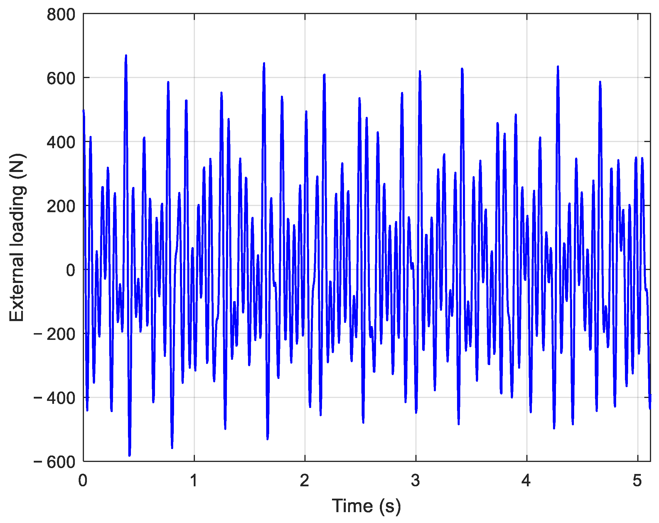
where A i , σ i , f i and φ i represent the amplitude, damping coefficient, frequency, and phase of ith component, respectively, and M is the number of external load components. The parameters for simulating the external load are listed in Table 1, while the time history of the external load is shown in Figure 4. The load was applied to the sixth DOF of the six-DOF system.
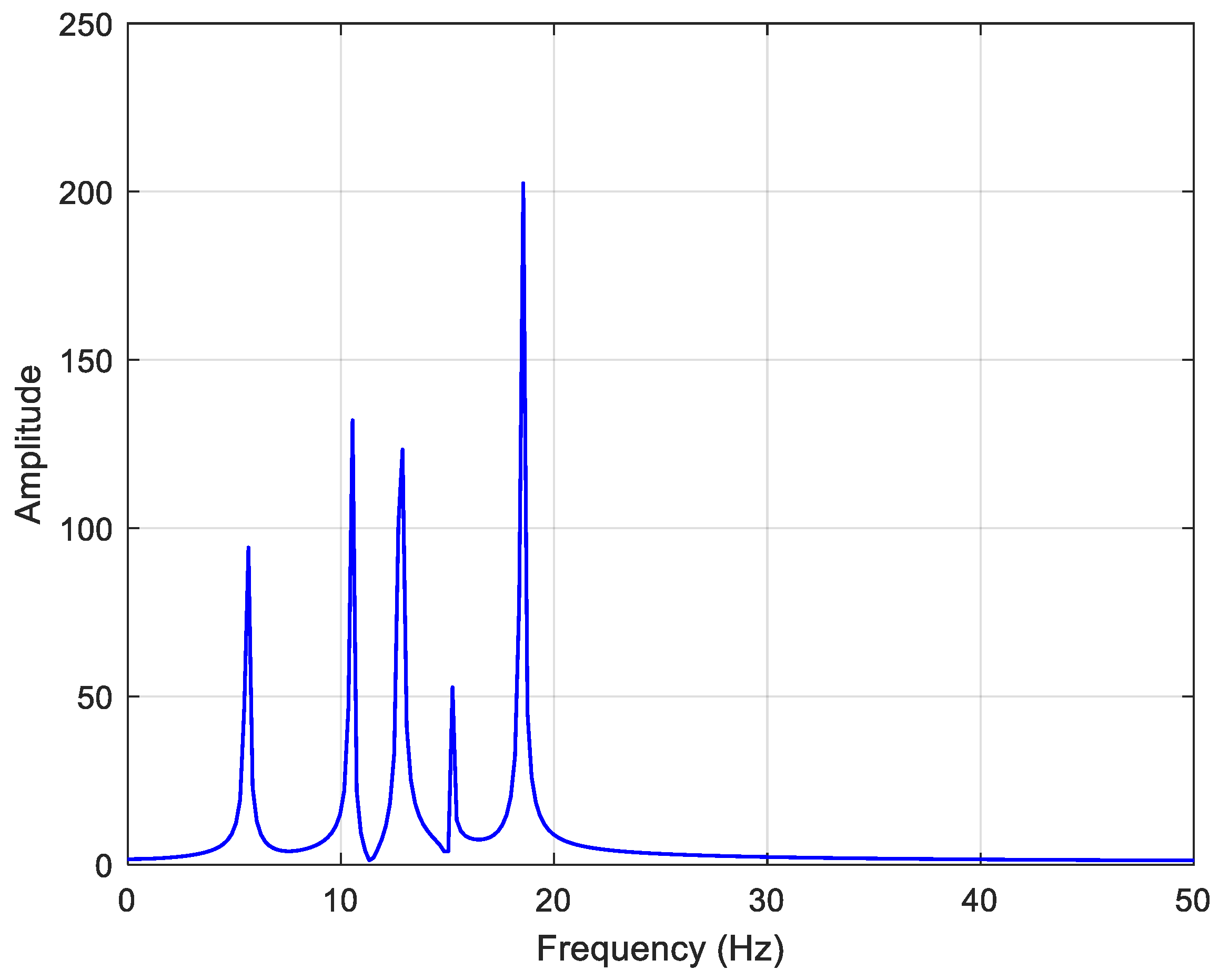
The external load acting on the six-DOF mass-damping-spring system was subjected to a Fourier transform, and its amplitude−frequency spectrum is shown in Figure 5. From the figure, it can be seen that the upper frequency limit of the external load is approximately 18.5 Hz. Comparing this with the natural frequencies of the six-DOF system, it is evident that the fifth and sixth modes have frequencies more than ten times higher than the upper limit of the external load frequency. Therefore, only the first four decoupled equations were considered in the calculation of the dynamic response of the six-DOF system.

3.1.2. Dynamic Response Calculation of Six-DOF System

Using the mode shapes of the six-DOF system, the vibration differential equations were decoupled, yielding the six modal masses, modal damping, and modal stiffness, as listed in Table 2.
Based on the frequency spectrum of the external loads, only the first four vibration modes were included in the dynamic response calculation after modal truncation. The external loads were applied only to the sixth DOF.
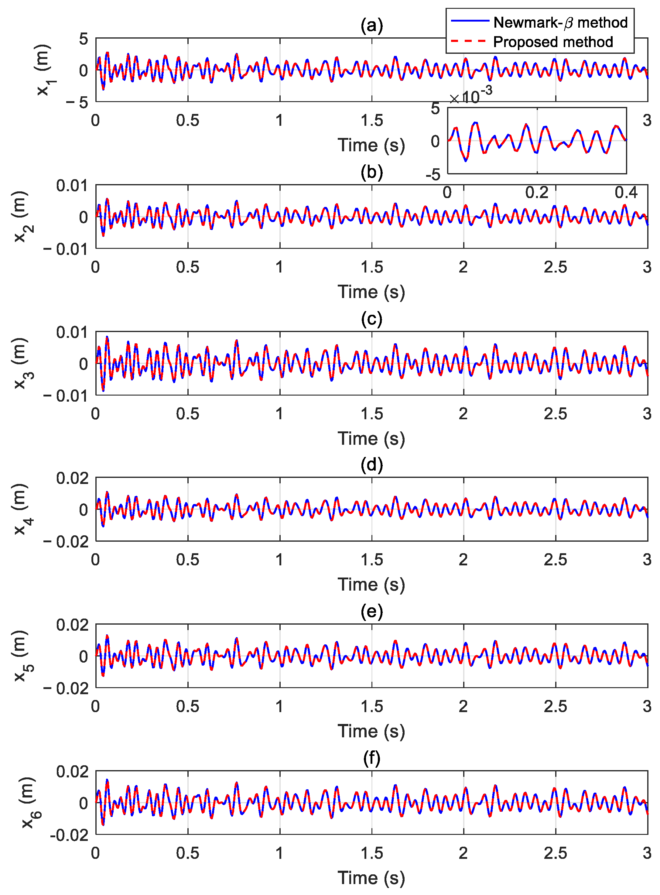
According to Equation (21), the conditions for i { i | ω i < 20 π f u } and j { j f j ( t ) 0 } result in the participation of the mode shape values ϕ 61 = 0.5507 , ϕ 62 = 0.5186 , ϕ 63 = 0.4565 and ϕ 64 = 0.3678 in the calculation. The dynamic response of the six-DOF system was calculated using both the proposed method and the Newmark-β method, and the results are compared in Figure 6. The good agreement between the two sets of results confirms the accuracy of the proposed method.

3.2. Jacket Foundation Structure

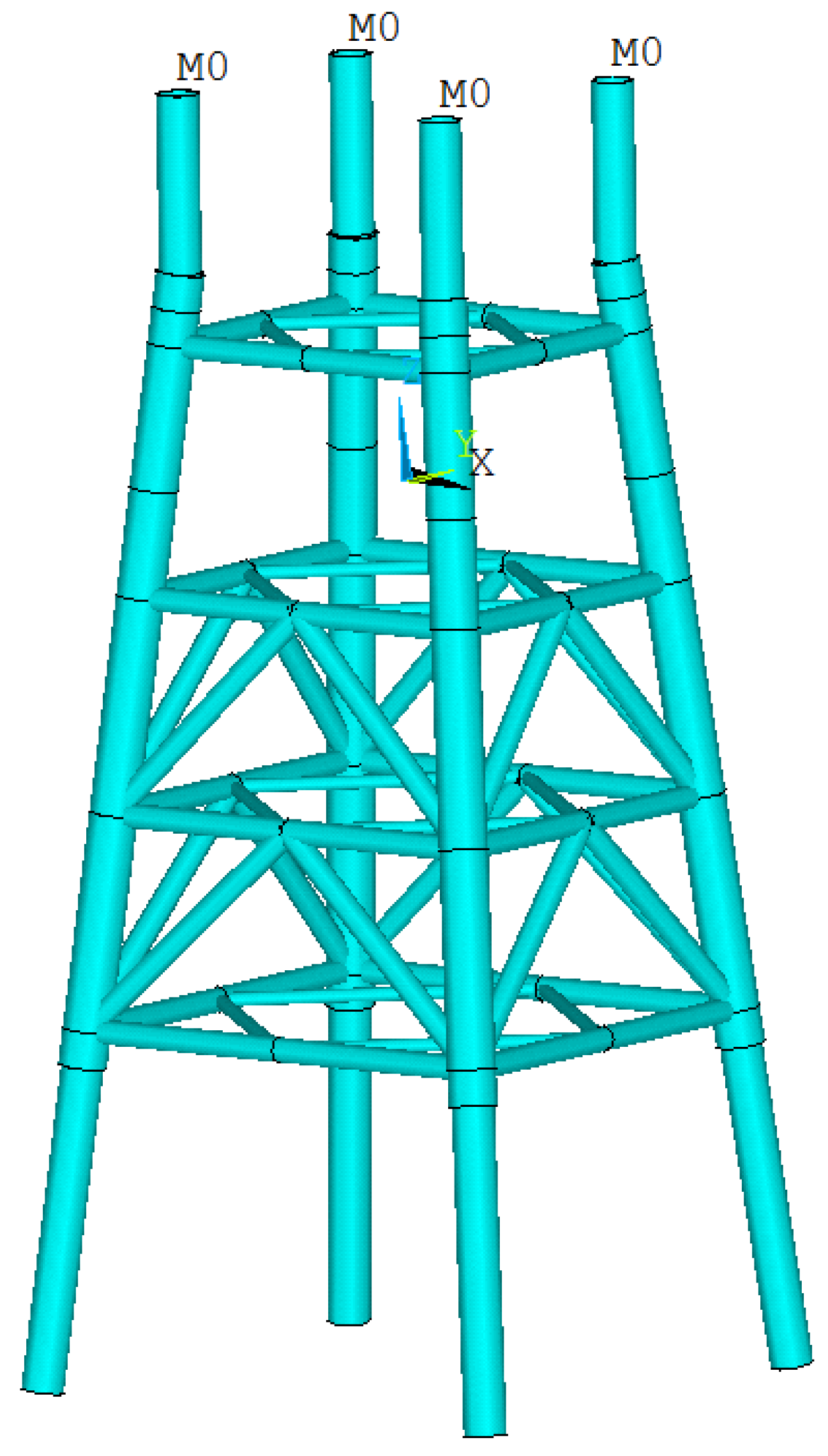
The offshore substation foundation is a four-legged jacket with internal piles that is located in a sea area with a water depth of approximately 15 m. The top elevation of the jacket is 6.0 m, and the top elevation of the first deck is 11.0 m. The jacket is made of steel, with the main legs having a cross-sectional diameter of 1372 mm and a wall thickness of 54 mm. The pile cross-section has a diameter of 1200 mm and a wall thickness of 30 mm. Horizontal braces are installed at elevations of 4.0 m, 0 m, −3.0 m, and −9.0 m. These horizontal braces have a cross-sectional diameter of 710 mm and a wall thickness of 20 mm. Diagonal braces are arranged within the plane of each horizontal bracing layer, with a cross-sectional diameter of 400 mm and a wall thickness of 15 mm. The vertical elevation between horizontal bracing layers adopts an inverted-V-shaped diagonal bracing configuration, with a diagonal brace diameter of 710 mm and a wall thickness of 20 mm. The upper substation module on the jacket was modeled as a concentrated mass with a total mass of 640 t that is distributed across four concentrated mass points, each with a mass of 160 t. The specific structural configuration of the jacket-type offshore substation foundation is shown in Figure 7.

3.2.1. Element Modal Analysis

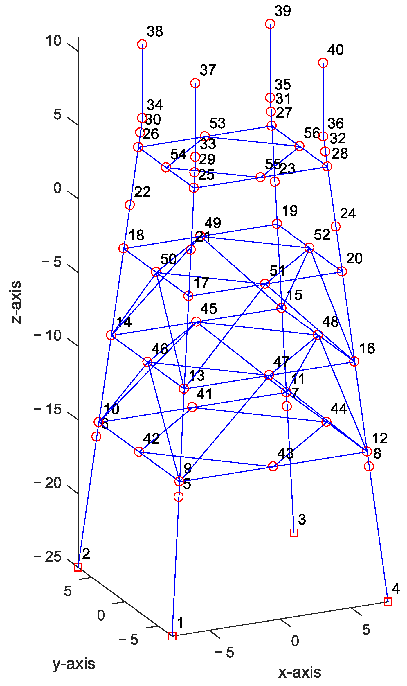
The finite element model of the offshore substation foundation structure was established. The foundation consists of five layers, including four middle horizontal bracing layers and a top layer. The nodes were numbered as shown in Figure 8. The offshore substation foundation structure includes 56 nodes, with four nodes fixed to the ground, resulting in a total of 312 DOFs. The mass and stiffness matrices of the structure were calculated using the finite element method. A finite element modal analysis was conducted to determine the natural frequencies of the structural vibrations. The frequency ranges from 1.0288 to 1.7828 × 10³ Hz, and the first 20 natural frequencies are listed in Table 3.

3.2.2. Dynamic Response Analysis

The wave forces acting on the foundation structure of the offshore substation were simulated using the following formula:
f ( t ) = i = 1 M A i cos ( 2 π f i t + φ i )
where A i , f i , and φ i represent the amplitude, frequency, and phase of each component of the wave force, respectively. The amplitude A i obeys the normal distribution N ( 1.5 × 10 5 , 5 × 10 2 ) ; the frequency f i obeys the normal distribution N ( 0.65 , 0.21 ) ; and the phase φ i obeys the uniform distribution U ( 0 , π ) . When the amplitude or frequency takes negative values, the absolute value is used. Since different sea areas exhibit distinct wave spectra, the wave force components are generated using random numbers, which makes the approach more universal.
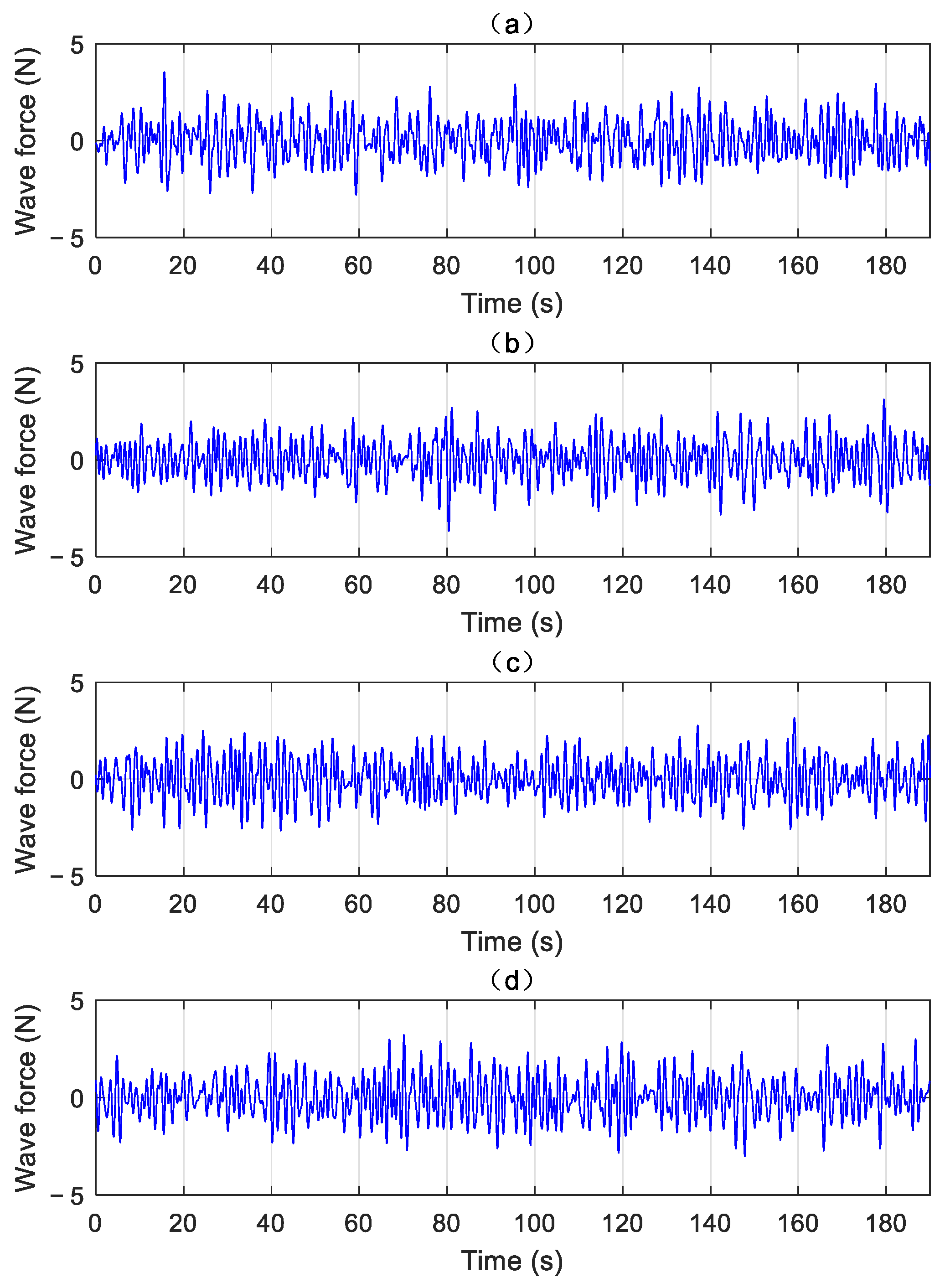
Let M = 100 , and use different random seeds to generate four wave forces. These forces are applied in the x-direction to nodes 5, 6, 7, and 8 of the offshore substation foundation structure. The time histories of the wave forces are shown in Figure 9.
The wave forces acting on the foundation structure of the offshore substation platform were subjected to Fourier transform, with the resulting amplitude−frequency characteristic curve shown in Figure 10. The figure indicates that the frequency range of the wave forces was 0–1.3 Hz. According to the theoretical derivation discussed above, when the natural frequency of the offshore substation platform foundation structure is higher than 10 times the upper limit of the wave frequency range, the corresponding modal response becomes negligible and can be omitted through modal truncation. This approach reduces the number of decoupled equations that need to be solved, thereby improving the efficiency of the dynamic response analysis for the offshore substation platform foundation structure.
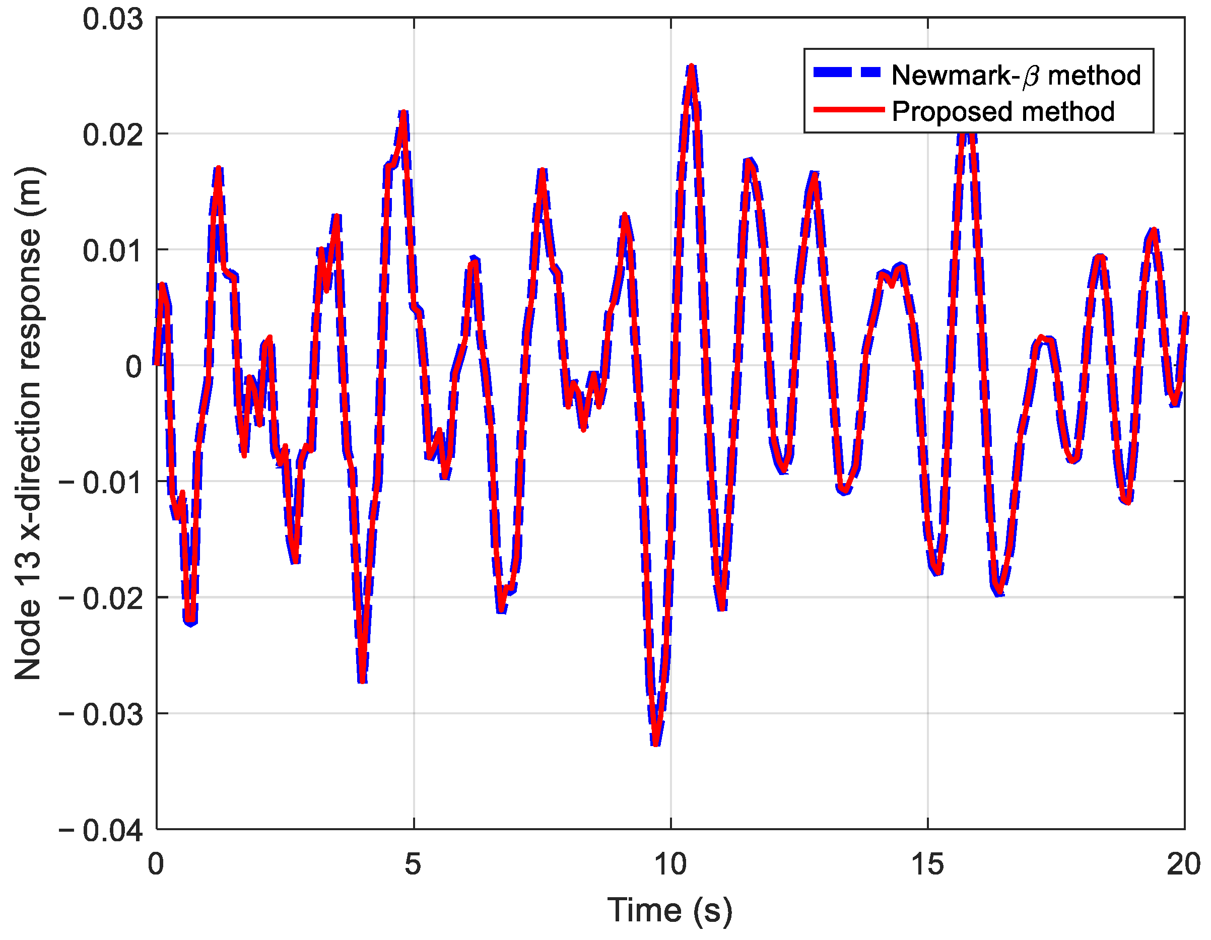
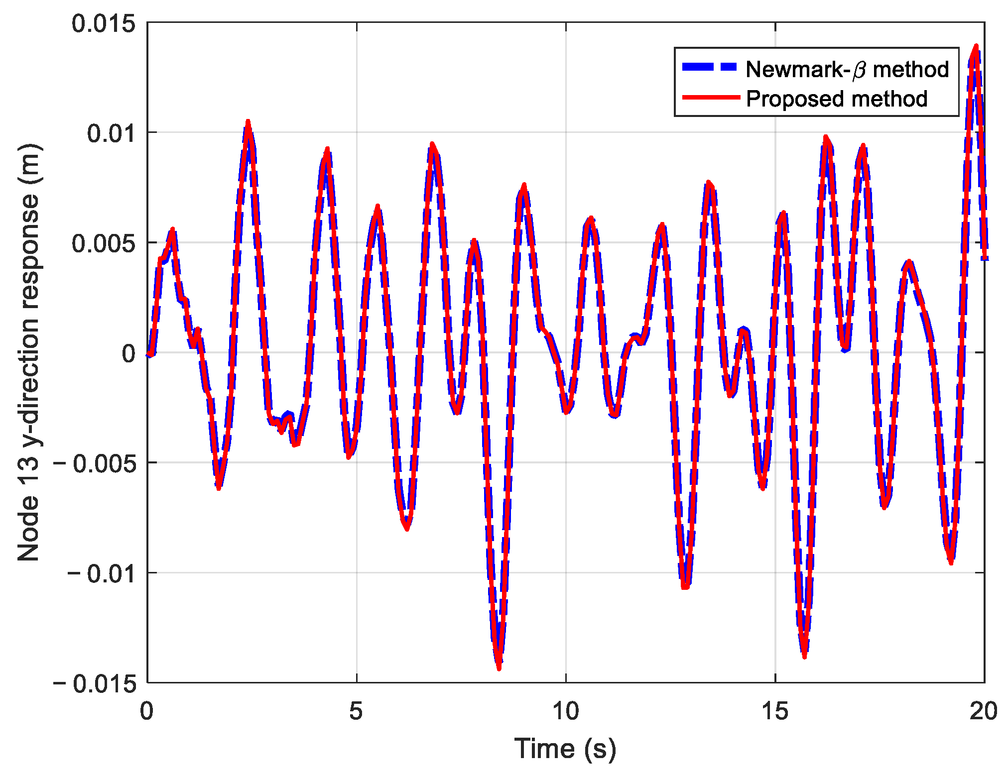
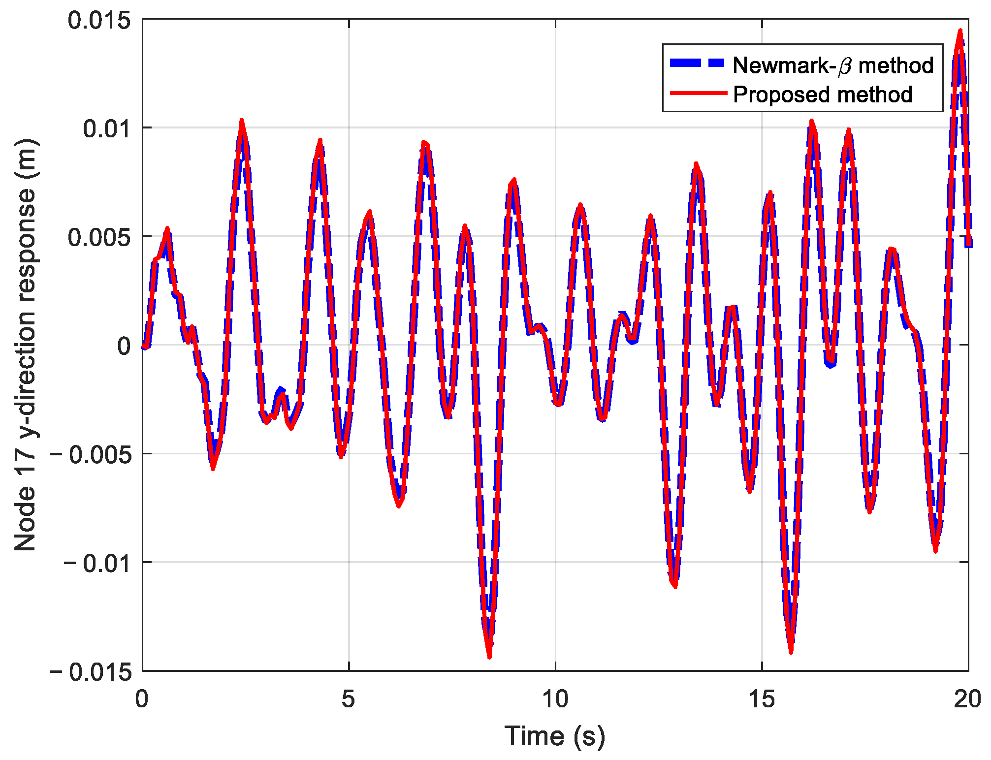
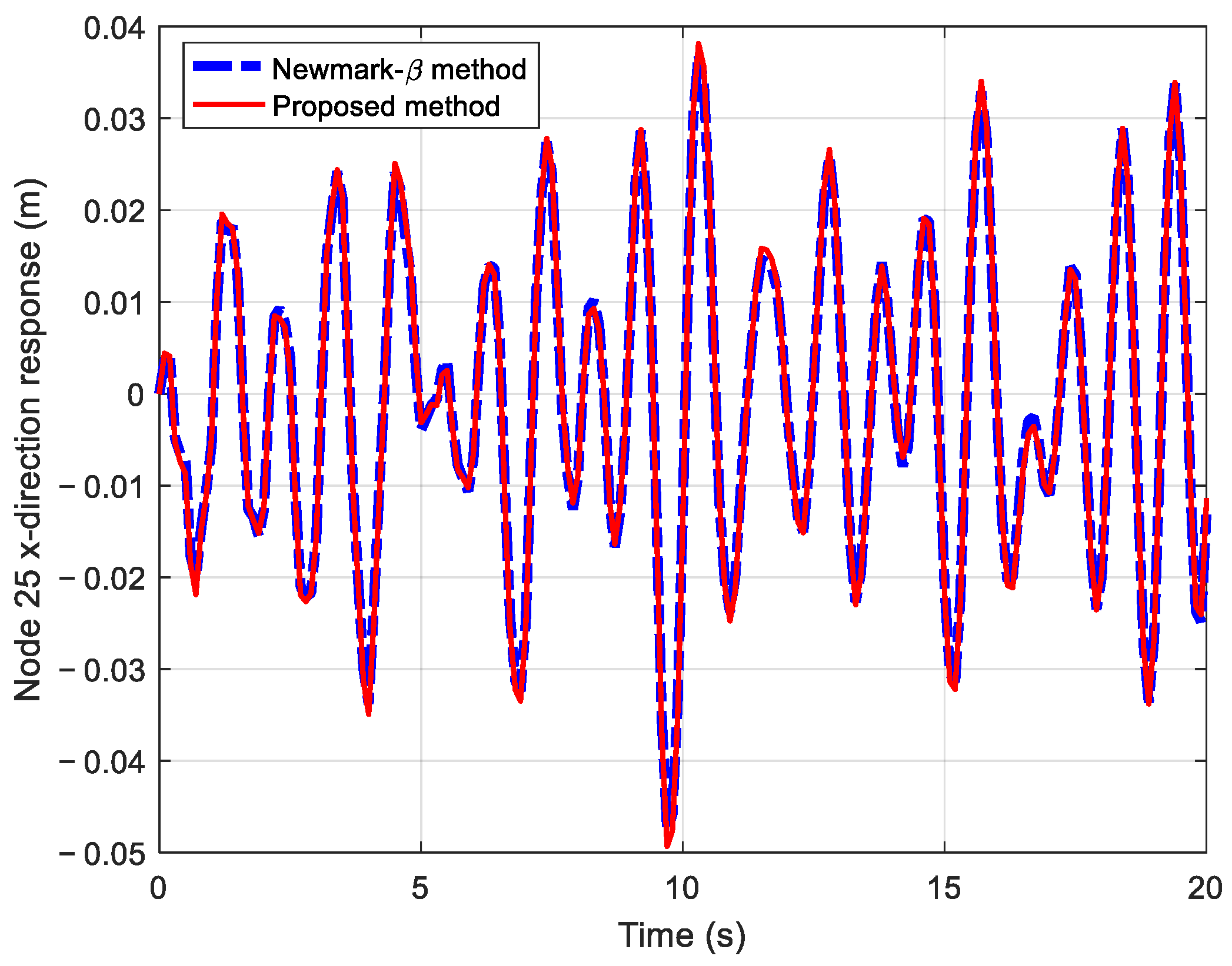
For the dynamic response calculation, the Rayleigh damping model is employed to simulate the vibration damping of the offshore substation foundation structure, with damping coefficients a = 2 × 10⁻⁴ and b = 2 × 10⁻³. The dynamic responses of the nodes in the lower, middle, and upper layers of the structure are calculated, focusing on the x and y direction responses of nodes 13, 17, and 25. These results were compared with those obtained using the Newmark-β method, as shown in Figure 11, Figure 12, Figure 13, Figure 14, Figure 15 and Figure 16. The close agreement between the two sets of results demonstrates the accuracy of the proposed method.
The Newmark-β method is a widely used approach for dynamic response analysis of structures. To estimate the calculation error of the method proposed in this paper, the results obtained from the Newmark-β method were used as the reference (true) values. The error was then estimated using the root mean square error (RMSE) method, as follows.
R M S E = 1 N i = 1 N ( x p r o p , i x n b , i ) 2
where x p r o p , i and x n b , i are the dynamic response calculated using the proposed and Newmark-β method and N is the total number of calculation points.
The analysis duration for the results shown in Figure 11, Figure 12, Figure 13, Figure 14 and Figure 15 was set to 20 s, with a time step length of 0.1 s, for a total of 201 calculation points. The root mean square error for the specified DOF was calculated using Equation (26), and the results are presented in Table 4.
As shown in Table 4, the root mean square errors are all relatively small, indicating that the calculation error of the method proposed in this paper is minimal.

3.2.3. Analysis of Computational Efficiency

The offshore substation foundation structure comprises 56 nodes and 312 DOFs. Using the Newmark-β method for calculation requires processing a 312 × 312 matrix at each time step. For larger-scale structures, the matrix size increases proportionally, which can easily lead to computer memory overflow and cause the dynamic response analysis to fail.
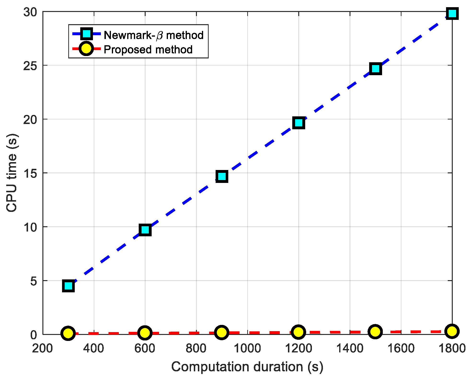
The method proposed in this paper reduces the number of decoupled equations from 312 to 9 through modal truncation and omission of minor mode shape values. This approach not only significantly reduces the computational load but also allows the response of each DOF to be calculated independently, thereby preventing the problem of computer-memory overflow.
Dynamic response calculations for the offshore substation foundation structure were performed using both the proposed method and the Newmark-β method. The computational platform featured an Intel i7-12700KF CPU with a clock speed of 3.61 GHz and 32 GB of RAM. The analysis durations were set to 300 s, 600 s, 900 s, 1200 s, 1500 s, and 1800 s, respectively. The computation times for each method were recorded and are listed in Table 5, and the results are plotted in Figure 17. The figure clearly demonstrates that the proposed method achieves significantly higher computational efficiency compared to the Newmark-β method.

4. Conclusions

This paper proposes an efficient method for the dynamic response analysis of the foundation structure of offshore substation platforms. The method achieves system decoupling through mode shapes and establishes a modal-truncation criterion based on the transfer coefficient. Throught the truncation of modes outside the frequency range of external loads, the number of decoupled equations is significantly reduced. This approach effectively addresses the challenges of low computational efficiency and potential infeasibility in dynamic response analysis for large-DOF foundation structures by discarding modes with negligible vibration responses. A six-DOF system and a finite element model of an offshore substation platform foundation structure were employed to test the performance of the proposed method. The results demonstrate the following: (1) the proposed method accurately calculates the dynamic responses of the two-test model; (2) the number of decoupled equations is reduced from 312 to 9, which improves the computational efficiency of the dynamic response analysis of the offshore substation platform foundation structure significantly, by approximately 100 times.

Author Contributions

Software, J.C.; Investigation, E.Z.; Writing—original draft, H.L.; Writing—review & editing, J.C. and E.Z.; Funding acquisition, J.C. All authors have read and agreed to the published version of the manuscript.

Funding

This research was funded by the National Natural Science Foundation of China (grant no. 52371296), the “CUG Scholar” Scientific Research Funds at China University of Geosciences (Wuhan) (grant no. 2022151), Technological Research Project of Power China Huadong Engineering Corporation Limited (grant nos. KY2024-XNY-02-05, KY2023-ZD-06), and Guangdong Basic and Applied Basic Research Foundation (grant no. 2022A1515240002).

Data Availability Statement

The data used and analyzed during the current study will be available from the corresponding author upon reasonable request after publication of this article.

Conflicts of Interest

Jiefeng Chen was employed by Power China Huadong Engineering Corporation Limited. The remaining authors declare that the research was conducted in the absence of any commercial or financial relationships that could be construed as a potential conflict of interest.

Abbreviations

M , C , K mass matrix, damping matrix, stiffness matrix
x ( t ) , x ˙ ( t ) , x ¨ ( t ) displacement, velocity, acceleration
f ( t ) external force acting on the structure
x k , x ˙ k , x ¨ k discrete displacement, velocity, acceleration
f k discrete external force
α , β parameters of Newmark-β method
a , b Rayleigh damping coefficients
Φ modal shape matrix
u ( t ) , u ˙ ( t ) , u ¨ ( t ) displacement, velocity, acceleration in modal space coordinate
m , c , k modal mass, damping, stiffness
m i , c i and k i diagonal elements of m , c and k
u i ( t ) , u ˙ i ( t ) and u ¨ i ( t ) the elements of vectors u ( t ) , u ˙ ( t ) and u ¨ ( t )
ϕ j i jth row and ith column element of Φ
N degree of freedom
i imaginary unit
U i ( i ω ) and F j ( i ω ) Fourier transform of u i ( t ) and f j ( t )
ω 0 and ω natural frequency and external load frequency
ζ damping ratio
f l and f u lower and upper limits of the wave load spectrum
DOFdegree of freedom
RMSroot mean square error

References

  1. Alassi, A.; Banales, S.; Ellabban, O.; Adam, G.; Maciver, C. HVDC Transmission: Technology Review, Market Trends and Future Outlook. Renew. Sust. Energy Rev. 2019, 112, 530–554. [Google Scholar] [CrossRef]
  2. Wang, H.J.; Liu, C.; Guo, Y.H.; Zhao, Y.; Li, X.Y.; Lian, J.J. Experimental and numerical research on the wet-towing of wide-shallow bucket jacket foundation for offshore substation. Ocean Eng. 2023, 175, 114126. [Google Scholar] [CrossRef]
  3. Kelma, S.; Schmoor, K.A.; Goretzka, J.; Hansen, M. Safety aspects for support structures of offshore wind turbines. Bautechnik 2014, 91, 543–553. [Google Scholar] [CrossRef]
  4. Solland, G.; Johansen, A. Design recommendations for grouted pile sleeve connections. Mar. Struct. 2018, 60, 1–14. [Google Scholar] [CrossRef]
  5. Jalbi, S.; Bhattacharya, S. Concept design of jacket foundations for offshore wind turbines in 10 steps. Soil Dynam. Earthq. Eng. 2020, 139, 106357. [Google Scholar] [CrossRef]
  6. Macangus-Gerrard, G. Offshore Electrical Engineering Manual, 2nd ed.; Elsevier: Amsterdam, The Netherlands, 2018; pp. 343–344. [Google Scholar]
  7. Schoefs, F.; Oumouni, M.; Ahmadivala, M.; Luxcey, N.; Dupriez-Robin, F.; Guerin, P. Unified System Analysis for Time-Variant Reliability of a Floating Offshore Substation. J. Mar. Sci. Eng. 2023, 11, 1924. [Google Scholar] [CrossRef]
  8. Xu, D.; Zhang, H.Y.; Tao, A.; Wang, K.; Su, K. Study on Structural Dynamic Response of Offshore Booster Station under Combined Wind, Wave and Current Loads. Water Power 2022, 48, 104640. [Google Scholar]
  9. Wang, Y.F.; Xu, C.H.; Yu, M.Z.; Huang, Z.C. Lightweight Design of Vibration Control Devices for Offshore Substations Based on Inerters. Sustainability 2024, 16, 3385. [Google Scholar] [CrossRef]
  10. Klose, M.; Dalhoff, P.; Argyriadis, K. Integrated load and strength analysis for offshore wind turbines with jacket structures. In Proceedings of the 17th (2007) International Offshore and Polar Engineering Conference, Lisbon, Portugal, 1–6 July 2007. [Google Scholar]
  11. Clough, R.W.; Penzien, J. Dynamics of Structures, 2nd ed.; McGraw-Hill Inc.: New York, NY, USA, 1993. [Google Scholar]
  12. Bishop, R.E.D.; Price, W.G. The generalized antisymmetric fluid forces applied to a ship in a seaway. Int. Shipbuild. Prog. 1977, 24, 3–14. [Google Scholar] [CrossRef]
  13. Jin, W.L.; Zhen, Z.S.; Zou, D.Q.; Li, H.B. Hybrid method for stochastic response analysis of offshore platform structures. Ocean Eng. 2001, 19, 14–19. [Google Scholar]
  14. Karadenia, H. Spectral analysis of offshore structures under combined wave and earthquake loadings. In Proceedings of the Ninth International Offshore and Polar Engineering Conference, Brest, France, 30 May–5 June 1999. [Google Scholar]
  15. Lu, H.C.; Fan, T.H.; Li, X.C.; Chen, C.H. A rapid time-continuous response analysis algorithm for offshore structures by combination of modal superposition and complex exponential decomposition. Ocean Eng. 2021, 234, 109272. [Google Scholar] [CrossRef]
  16. Craig, R.R.; Kurdila, A.J., Jr. Fundamentals of Structural Dynamics, 2nd ed.; John Wiley & Sons, Inc.: Hoboken, NJ, USA, 2006. [Google Scholar]
  17. Veletsos, A.S.; Ventura, C.E. Efficient analysis of dynamic response of linear systems. Earthq. Eng. Struct. Dynam. 1984, 12, 521–536. [Google Scholar] [CrossRef]
  18. Veletsos, A.S.; Ventura, C.E. Dynamic analysis of structures by the DFT method. J. Struct. Eng. 1985, 111, 2625–2642. [Google Scholar] [CrossRef]
  19. Mansur, W.J.; Carrer, J.A.M.; Ferreira, W.G.; Claret de Gouveia, A.M.; Venancio-Filho, F. Time-segmented frequency-domain analysis for non-linear multi-degree-of-freedom structural systems. J. Sound. Vib. 2000, 237, 457–475. [Google Scholar] [CrossRef]
  20. Mansur, W.J.; Soares, D., Jr.; Ferro, M.A.C. Initial conditions in frequency-domain analysis: The FEM applied to the scalar wave equation. J. Sound. Vib. 2004, 270, 767–780. [Google Scholar] [CrossRef]
  21. Lee, U.; Kim, S.; Cho, J. Dynamic analysis of the linear discrete dynamic systems subjected to the initial conditions by using an FFT-based spectral analysis method. J. Sound. Vib. 2005, 288, 293–306. [Google Scholar] [CrossRef]
  22. Liu, F.S.; Li, H.J.; Wang, W.Y.; Liang, B.C. Initial-condition consideration by transferring and loading reconstruction for the dynamic analysis of linear structures in the frequency domain. J. Sound Vib. 2015, 336, 164–178. [Google Scholar] [CrossRef]
  23. Huang, W.P.; Bai, X.L. Structural Dynamic; Modern Education Press: Beijing, China, 2010. [Google Scholar]
  24. Rayleigh, L. Theory of Sound; Dover: New York, NY, USA, 1945; Volume 1. [Google Scholar]
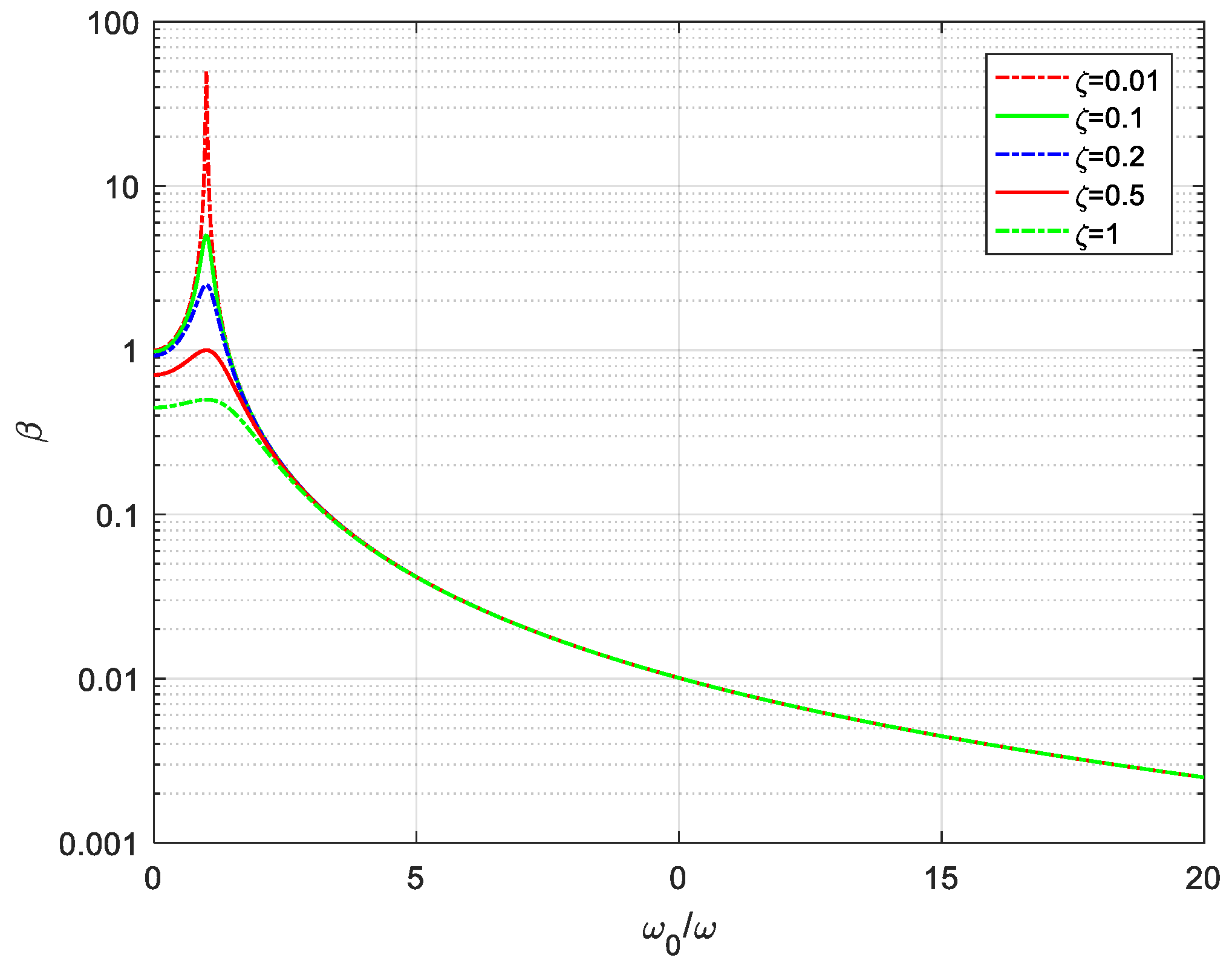
Figure 1. Plot of β varying with the frequency ω 0 / ω .
Jmse 13 00750 g001
Figure 2. Flowchart of proposed method.
Jmse 13 00750 g002
Figure 3. Six-DOF mass-damping-spring system.
Jmse 13 00750 g003
Figure 4. Time history of external loading.
Jmse 13 00750 g004
Figure 5. Spectrum of external loading.
Jmse 13 00750 g005
Figure 6. Comparison of dynamic responses under external loading: (a) x 1 ( t ) ; (b) x 2 ( t ) ; (c) x 3 ( t ) ; (d) x 4 ( t ) ; (e) x 5 ( t ) ; (f) x 6 ( t ) .
Jmse 13 00750 g006
Figure 7. Foundation of offshore substation platform.
Jmse 13 00750 g007
Figure 8. Node numbering for offshore substation foundation structure.
Jmse 13 00750 g008
Figure 9. Forces acting on the offshore substation foundation structure in the following directions: (a) node 5 in the x-direction; (b) node 6 in the x-direction; (c) node 7 in the x-direction; (d) node 8 in the x-direction.
Jmse 13 00750 g009
Figure 10. Wave-force spectrum plot for the offshore substation foundation structure.
Jmse 13 00750 g010
Figure 11. Dynamic response of node 13 in the x-direction for the offshore substation foundation.
Jmse 13 00750 g011
Figure 12. Dynamic response of node 13 in the y-direction for the offshore substation foundation structure.
Jmse 13 00750 g012
Figure 13. Dynamic response of node 17 in the x-direction for the offshore substation foundation structure.
Jmse 13 00750 g013
Figure 14. Dynamic response of node 17 in the y-direction for the offshore substation foundation structure.
Jmse 13 00750 g014
Figure 15. Dynamic response of node 25 in the x-direction for the offshore substation foundation structure.
Jmse 13 00750 g015
Figure 16. Dynamic response of node 25 in the y-direction for the offshore substation foundation structure.
Jmse 13 00750 g016
Figure 17. Comparison plot of computation time between the proposed method and the Newmark-β method.
Jmse 13 00750 g017
Table 1. Parameters of external loading.
Component A i σ i f i φ i
1150010.5 π / 12
21200.025.6 π / 6
32000.0512.8 π / 3
4500.0115.2 π / 4
5230018.5 π / 3
Table 2. Modal mass, damping, and stiffness of six-DOF mass-damping-spring system.
Order m i c i k i
112.90582.9058 × 104
2125.14892.5149 × 105
3164.53956.4540 × 105
41112.05371.1205 × 106
51156.80651.5681 × 106
61188.51561.8855 × 106
Table 3. First 20 natural frequencies of the offshore substation foundation.
OrderFrequency (Hz)OrderFrequency (Hz)
11.0288115.1716
21.04041210.9985
31.14151311.4781
42.02431411.5403
52.15951512.4356
62.18151613.3252
72.18521715.4094
82.19141815.5904
94.40291918.2234
104.43522018.5487
Table 4. Computational error of structural dynamic response.
DOFRMSE
Node 13, x-direction0.00024265
Node 13, y-direction0.00018149
Node 17, x-direction0.00048893
Node 17, y-direction0.00033327
Node 25, x-direction0.00096182
Node 25, y-direction0.00044151
Table 5. Comparison of computation time between the proposed method and Newmark-β method.
Computation Duration (s)Computation Time with Proposed Method (s)Computation Time with Newmark-β Method (s)
3000.067644.5073
6000.11029.7071
9000.144514.6700
12000.185319.6525
15000.222624.6802
18000.261529.8099
Disclaimer/Publisher’s Note: The statements, opinions and data contained in all publications are solely those of the individual author(s) and contributor(s) and not of MDPI and/or the editor(s). MDPI and/or the editor(s) disclaim responsibility for any injury to people or property resulting from any ideas, methods, instructions or products referred to in the content.