1. Introduction
Natural gas hydrate is a solid compound of natural gas and water under low temperature and high pressure, mainly found in the ocean and permafrost. More than 90% of these hydrates occur in clay siltstone or medium silty seafloor sediments [
1,
2,
3]. Global hydrate resources account for more than twice the global conventional oil and gas resources [
4]. China’s gas hydrate exploration assessment and drilling have confirmed over 100 billion square meters of gas hydrate reserves in the Shenhu Sea area [
5].
As a promising new type of clean energy, the efficient exploitation of natural gas hydrate has attracted great attention worldwide [
6,
7,
8]. At present, more than 30 countries and regions have launched geological exploration and research on gas hydrates, including on-site test production work in Markley in Canada, the Alaskan tundra in the United States, the Nanhai Trough in Japan, and the Shenhu Sea in the South China Sea [
9,
10,
11,
12,
13,
14]. In 2020, China carried out a second test in the Shenhu Sea area of the South China Sea and applied horizontal well production for the first time in the world. This changed the situation in which all countries use single vertical well production in the early stage, yielding little gas and a substantial amount of sand, which was not easy for normal production. Natural gas hydrate is gradually entering a new stage, moving from exploratory testing to experimental testing [
15].
Geological modeling is the research basis for regional geological surveys, resource exploration, development, etc. At present, there is no mature method for the geological modeling of hydrates. As a solid in the subsurface, natural gas hydrate is usually associated with gas and water, and its seismic and logging response characteristics are exceptional, which poses great challenges to formation classification and correlation and geological modeling. Because of limited geological and test well data, current hydrate geological models are relatively simple, mostly single-well homogeneous or only longitudinal heterogeneous. There is little research on 3D heterogeneous geological models of actual multi-wells [
16,
17,
18,
19,
20]. Ye Hongyu et al. (2022) established a longitudinal heterogeneity model of a single well with a single hydrate layer based on production well testing data at the Nankai Trough in Japan [
21].
The gas hydrate in the Shenhu area of the South China Sea is a clayey siltstone reservoir, which is shallow in depth, loose in texture, and weakly cemented or uncemented, with high clay mineral content, fine pore throat size, and obvious ultra-low permeability characteristics; the area also develops a gas hydrate layer, a three-phase mixed layer, and a gas–water two-phase layer; i.e., multiple layers and phases coexist [
22]. Although extensive geological studies have been conducted on natural gas hydrates in the South China Sea, the established geological models do not fully reflect the non-uniformity and peculiarity of the reservoir and the three-phase mixed layer [
23]. In this study, based on the actual data from the two test production wells in the Shenhu area of the South China Sea, the gas hydrate layer, the three-phase mixed layer, and the free gas layer are divided into three geological bodies, and the layers are reclassified. The porosity, permeability, saturation, pressure, and temperature models of the four wells in the test area were constructed using Petrel software, and the resource volume in the test area was estimated in a three-dimensional non-uniform geological model, providing a geological basis for natural gas hydrate exploitation research.
2. Geological Setting
The Baiyun Depression in the north of the South China Sea is the largest depression in the Pearl River Estuary Basin. The Shenhu area of the South China Sea is structurally part of the Zhuer Depression of the Pearl River Estuary Basin. The seafloor topography is complex, and the general trend is higher in the north and lower in the south. During the Cenozoic, many regional tectonic activities occurred, such as the Shenhu movement, Zhuqiong movement, Nanhai movement, and Dongsha movement, which resulted in a high sedimentation rate of formations and rich oil and gas resources [
24]. The water depth of hydrates in the Shenhu Sea is 500–2000 m, the seafloor temperature is 2–4 °C, and the geothermal gradient is 44–67 °C/km [
25]. The Eocene Wenchang Formation and the Oligocene Enping Formation are the main source rocks with high maturity, generating pyrolysis gas at depth in the formation. The Upper Ocene Zhujiang Formation, Hanjiang Formation, Yuehai Formation, and Wanshan Formation have low organic matter maturity and produce a large amount of shallow biogenic gas. Deep pyrolysis gas and shallow biogenic gas provide sufficient gas sources for hydrate formation [
26,
27,
28]. Faults, mud diapirs, and gas chimneys in the region form gas migration channels, and most of them directly communicate with the Bottom Simulating Reflector (BSR) [
29]. Sufficient gas supply, high pressure, low temperature, and well-established gas migration pathways create ideal conditions for hydrate formation. The Shenhu Sea area has become an important target area for marine gas hydrate exploration and development in China [
30].
Since 2003, the China Geological Survey has been conducting a survey and evaluating natural gas hydrate resources in the Shenhu area. The first actual sample of natural gas hydrate was obtained in 2007. Gas hydrate exploration in 2015 and 2016 resulted in the discovery of eight gas hydrate deposits. In 2017, the W11–W17 deposit was selected as the best target for production testing [
14] (
Figure 1).
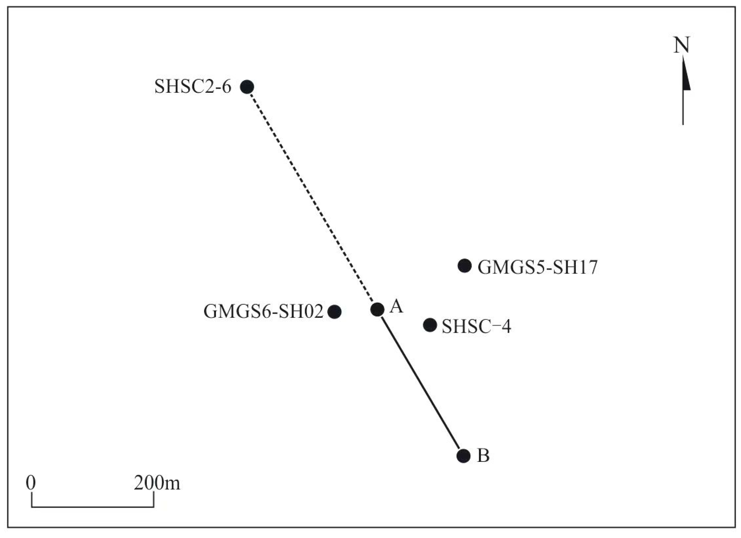
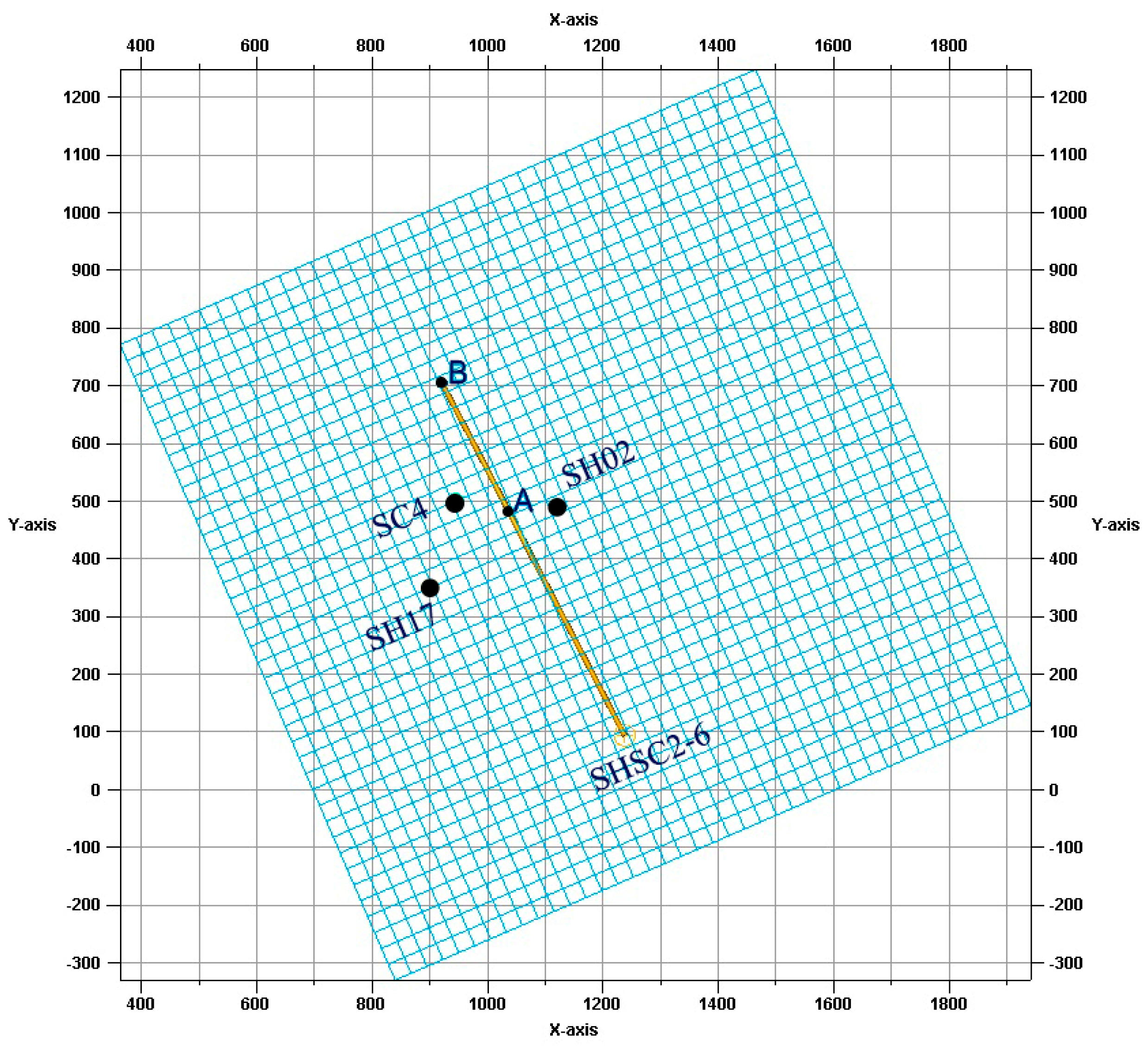
Both of China’s two test operations in the Shenhu area of the South China Sea were conducted in the W11–W17 orebody. The distance from W11 to W17 is approximately 2 km. The two test holes are located near W17, and four holes are currently being drilled. W17 was an early well, now known as GMGS5-SH17.
The first test well was the vertical well SHSC-4, the second was the horizontal well SHSC2-6, and the well GMGS6-SH02 was the pilot hole drilled for the optimal trajectory of the second test well in 2019. The distance between well GMGS6-SH02 and well A is approximately 70 m [
15], the distance between well GMGS5-SH17 and well A is approximately 230 m [
23], and the distance between well SHSC-4 and well A is 189 m. Test well SHSC-4 is 90 m away from test well SHSC2-6 and 155 m from well GMGS5-SH17 (
Figure 1).
3. Methodology
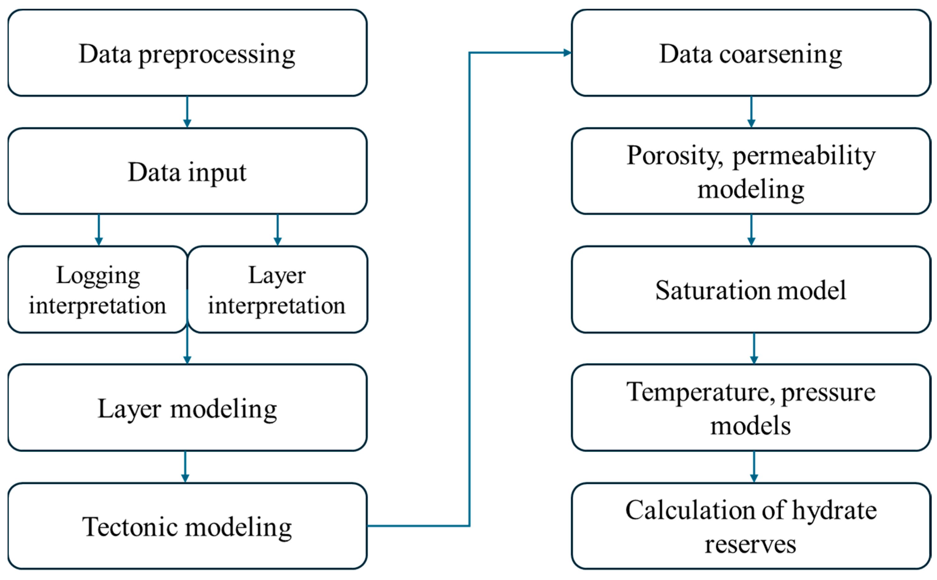
Geological modeling methods include deterministic modeling and stochastic modeling. Building a three-dimensional geological model requires a large amount of base data, including seismic, well logging, and drilling data. With good quality seismic data and full utilization of well data, a good deterministic model can be obtained. However, in most cases, the conditions for deterministic modeling are difficult to guarantee, so the modeling method development has focused on stochastic reservoir modeling based on geostatistics. Stochastic modeling recognizes that, under current conditions, people can gain a clear understanding of underground reservoirs with minimal information and that it is, therefore, necessary to fully consider the various possible outcomes caused by this uncertainty when building geological models, which can be analyzed or selected by geologists. As there is limited information on natural gas hydrates, this paper refers to well locations and seismic and well logging data, performs geological correlation, and uses stochastic modeling to build a well, layer, and attribute model. It uses deterministic modeling to establish temperature, and pressure models and finally constructs a three-dimensional heterogeneous geological model and calculates the resource volume of natural gas hydrates (
Figure 2).
The main method used in this paper to construct geological models is the corner point grid method. By selecting the corner point grid model as the basis for geological modeling, the technical approach to geological modeling can be determined. First, a column set is generated, and then, layers are inserted into the column set to generate topological hexahedral elements to reflect layer termination through changes in z-value and to express geological phenomena such as layer termination through the effectiveness of local subdivision mesh bodies.
The modeling steps based on the corner point grid model are as follows:
Construct a layer model based on drilling, logging, and seismic data and handle the contact relationships between layers.
Construct a three-dimensional framework based on the stratigraphic model to establish the structural model, ensuring each grid is normal.
Coarsen the well-point grid property parameter set in the generated structural model and determine the appropriate modeling parameters through data analysis.
Complete the construction of the porosity and permeability attribute model using kriging and other interpolation methods.
Construct the water, gas, and hydrate saturation models using porosity as a co-Kriging variable.
Calculate the temperature and pressure models based on the temperature and pressure gradients.
Calculate the hydrate reserves.
4. Results
Based on the data of two hydrate test wells in the Shenhu area of the South China Sea, the hydrate, mixed, and free gas layers are divided into three geological bodies. Based on the well data of the three wells and the regional seismic data, the fault model and the three-dimensional skeleton were constructed successively, and then, the layer model was constructed. By combining the established model data with the dataset of physical property parameters, the attribute model was established, and the porosity, permeability, saturation, pressure, and temperature models of the three wells in the test production area were determined. The estimated resource in the test production area provides a geological basis for the study of gas hydrate exploitation.
4.1. Data Input
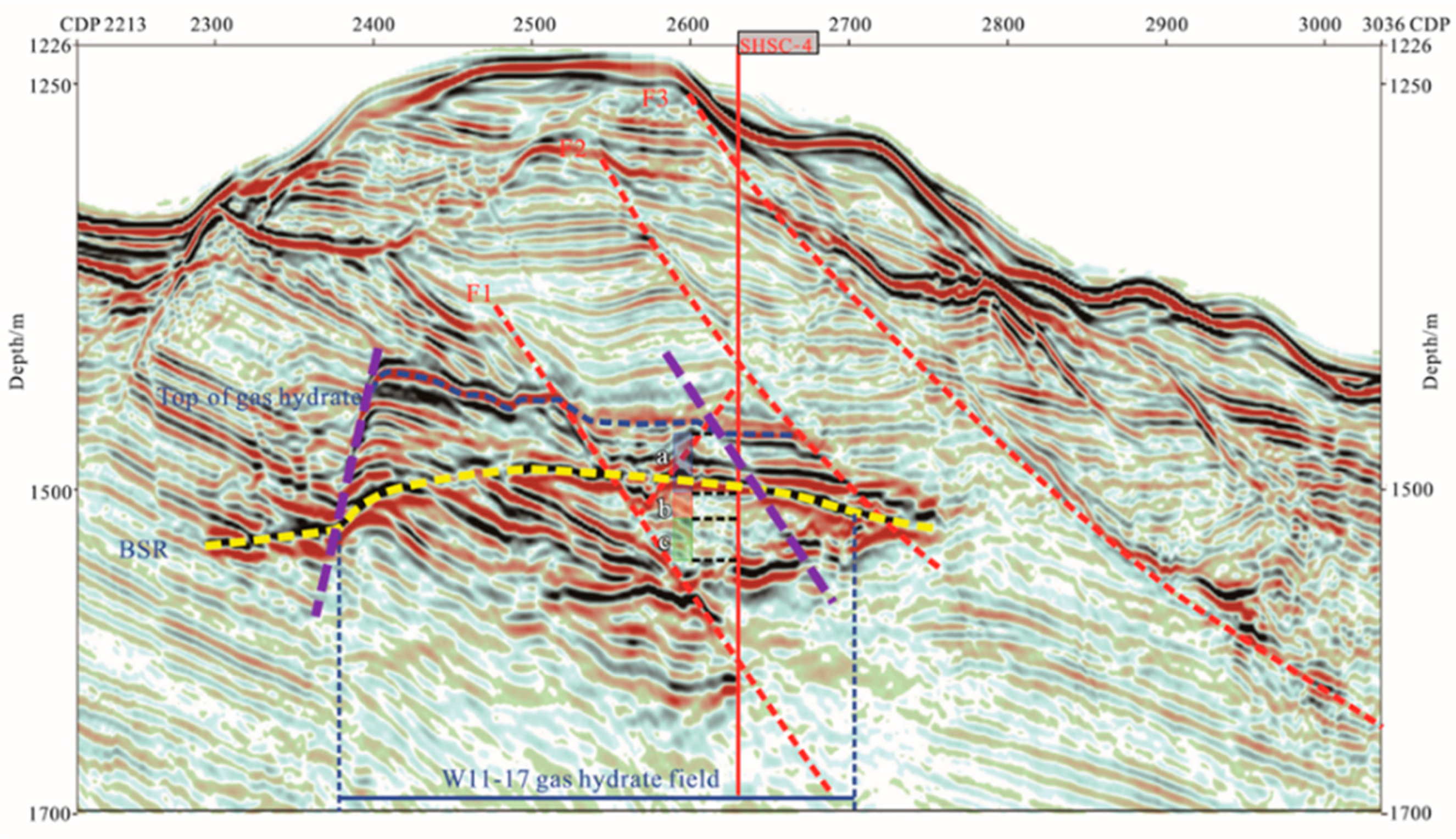
The test production area is covered by three-dimensional seismic data, which shows typical high amplitude reflection features similar to those observed in submarine reflection (BSR). As seen from the seismic section of the SC-4 well, the first test production well in the area, the faults are clearly delineated. Three reservoir sets—a, b, and c—have developed in the vicinity of the Bottom Simulating Reflector (BSR) in the seismic profile. The original interpretation of the seismic section identified only four faults. However, detailed analysis of the seismic reflection data combined with fault characteristics identified a new synthetic normal fault between fault F1 and fault F2 in section W11–W17. This fault is causing displacement of part of the hydrate-bearing strata in reservoir A in well SHSC-4. In addition, the previously interpreted antithetic normal fault may not exist based on the displacement of the seismic reflection axes (
Figure 3).
The logging response characteristics of the three vertical wells, SHSC-4, GMGS6-SH02, and GMGS5-SH17, indicate that three sets of muddy siltstone reservoirs were drilled from top to bottom of the two wells. These include a hydrate layer, a mixed gas/hydrate layer, and a free gas layer. The geological and physical parameters of each layer are shown in
Table 1 [
14,
15,
31].
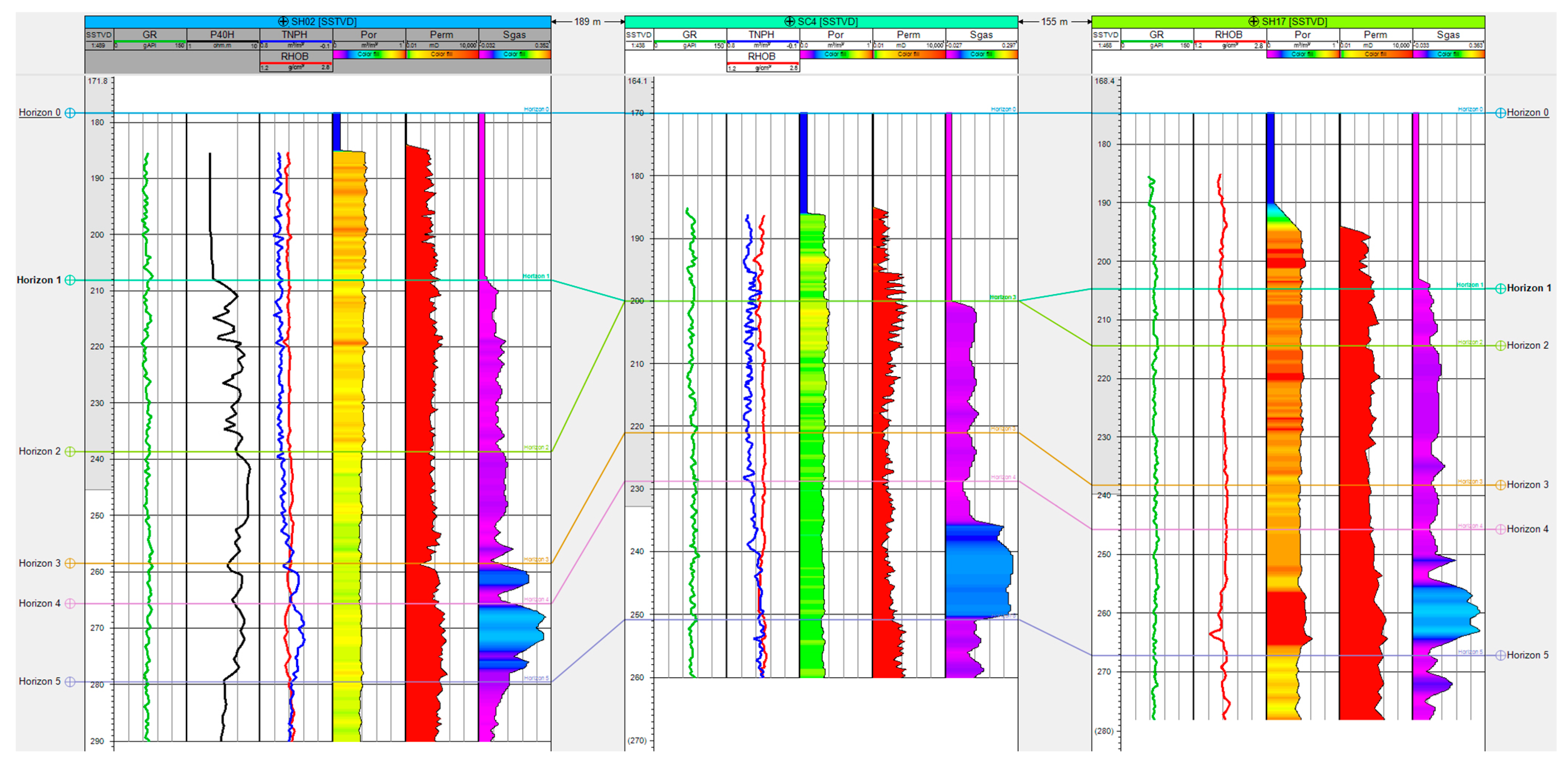
The logging curves of the three vertical wells in the test production area primarily comprise gamma (GR), resistivity (P40H or RES_BD), neutron porosity (TNPH), volume density (RHOB), and other data. The physical properties of the rock are porosity (POR), permeability (PERM), and saturation of hydrate, gas, and water (Sgh, Sg, and Sw, respectively). Based on the response characteristics of seismic and logging and core analysis, the unified marker layer is initially identified. After that, the isochronous correlation method of sequence stratigraphy is employed for the correlation division of strata. The vertical layers can be classified into five categories: two hydrate layers, two mixed layers, and one free gas layer. Based on the core analysis results, drilling, seismic data, and logging interpretation, a tectonic map and a geological profile of the hydrate test production area were constructed (
Figure 4 and
Figure 5, respectively).
4.2. Structural Modeling
4.2.1. Meshing
According to the research objectives and requirements, the operational efficiency of the dynamic model is improved. At the same time, the reservoir heterogeneity is reflected to some extent, and whether the model domain, grid direction, step size, grid height, and total number of grids are satisfied is comprehensively considered. There are many grid types in geological modeling, such as corner grid, orthogonal grid, unstructured grid, and so on, each of which has its advantages and scope of application. This model uses a corner grid. The model boundary and grid settings are shown in
Figure 6. The grid I/J/K number is 40 × 40 × 50, the grid length in the X and Y directions is 30 × 30, the angle is 23.4°, and the longitudinal grid thickness is nearly 3 m.
4.2.2. Stratigraphic Divisions
Based on the response characteristics of the logging curves, in particular, the gamma ray, resistivity, neutron, and density logs, and in combination with the 3D exploration seismic section, the formation correlation and fine stratigraphic subdivision of the three wells SH02-SC4-SH17 were carried out. The comparison results show that the top Zone 0 (Horizon 0–Horizon 1) is a stable cap layer in this region with low gamma ray variation amplitude, medium porosity and permeability, but low gas saturation. The distribution of zones 1–4 (Horizons 1–5) is relatively stable, and the three wells have been essentially drilled. However, according to seismic data and well log information, the Horizon 1 layer of the SC4 well has been lost. In addition, Zones 1–3 has relatively high resistivity but low gas saturation. Zone 4 has relatively high resistivity and high gas saturation (above 0.28), which is the main target horizon in this area. The log response characteristics of each layer and the split and comparison results of the small layers are shown in
Figure 7. The thickness distribution of each interval is shown in
Figure 8.
4.2.3. Layer Model
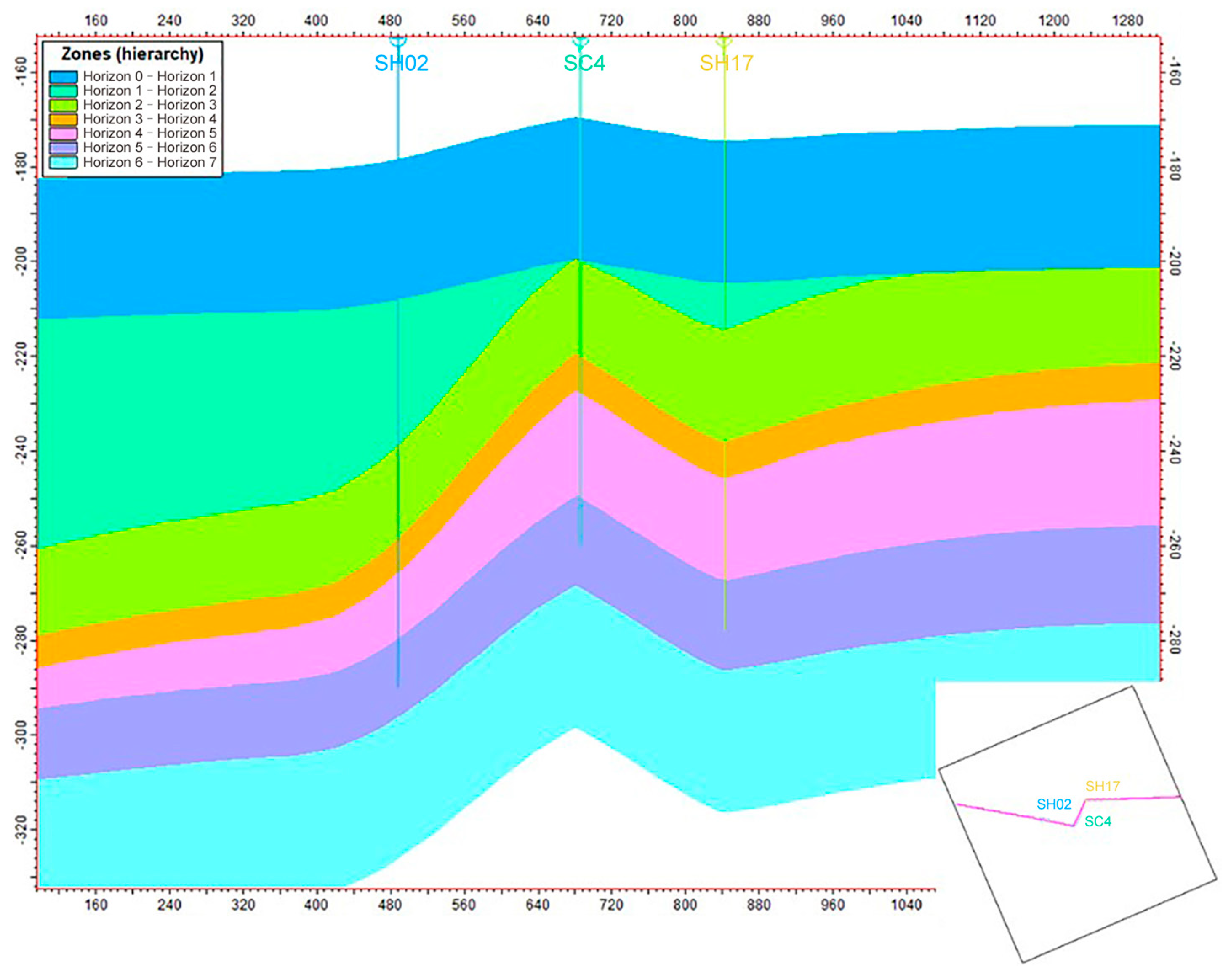
The isochronous stratigraphic framework is generally established under the guidance of sequence stratigraphy to provide basic constraints for establishing tectonic planes. At the same time, it provides information on contact relationships, such as integration, overlap, and denudation, for establishing the stratigraphic model. According to the sequence stratigraphy knowledge, the reservoir peaks in Horizon 1 at the position of well SC4, and the stratigraphic model is shown in
Figure 9.
4.3. Property Modeling
Attribute models include porosity, permeability, and saturation models. The porosity and permeability models directly reflect the heterogeneity within the reservoir, especially the permeability model, which has a large influence on pressure and temperature and directly affects production. The saturation model reflects the spatial variation of flow, indicating that the moving position of the hydrate decomposition front is an important indicator of gas and water production. The porosity model, permeability model, and saturation model were calculated using the sequential Gaussian simulation method, and the variation function parameters were also adopted. The source direction was set to northeast, and the parameters of the main variable range, secondary variable range, and vertical variable range were selected according to the data analysis.
Gaussian random fields are the most classical stochastic functions. Sequential Gaussian simulation is a stochastic simulation method that applies Gaussian probability theory and sequential simulation algorithm to generate spatial distribution of continuous variables. The algorithmic simulation process is as follows: first, data transformation is performed on the data to ensure that the input data conform to the standard normal distribution; random paths are determined to ensure that each grid node is accessed once per visit; the variational function model and the kriging method are used to determine the cumulative probability distribution function (ccdf) of the stochastic function Y(u) at the grid to be simulated; then, a quantile is randomly extracted from the ccdf, i.e., a random quantile is then extracted from the ccdf to obtain the simulated value of the grid, which is added to the known data set; the simulation is then performed at the following grid node along the random path until each node is simulated; and finally, the random simulation realization is subjected to a back transformation to obtain a simulation realization [
32].
4.4. Pressure and Temperature Field Modeling
The temperature and pressure field models effectively reflect the spatial variations of temperature and pressure in their original state in three-dimensional space. Formation pressure and formation temperature are key parameters that vary with depth. The temperature and pressure field models are established using a deterministic modeling approach.
The actual temperature of the seabed formation is calculated as follows:
where
T0 is the seabed temperature (°C), Δ
T is the geothermal gradient (°C/m), and
H is the formation burial depth (m).
According to regional geological studies, the seafloor temperature in the Shenhu area ranges from 3.3 to 3.7 °C, with a geothermal gradient of 4.5 to 6.7 °C per 100 m [
26]. The geothermal gradient varies from 29.4 to 52.2 °C/km, with an average of 39.1 ± 0.74 °C/km [
33]. In the model, the initial temperature field distribution is determined using a seafloor surface temperature of 3.3–4.82 °C and a geothermal gradient of 0.039 °C/m. Quantitative analysis of the computational results indicates that the initial temperature at the bottom of the hydrate reservoir is approximately 14–15 °C. The pressure field is determined by fitting the measured pressure data to depth, resulting in the following formula for seabed formation pressure:
where
Z represents elevation depth (m).
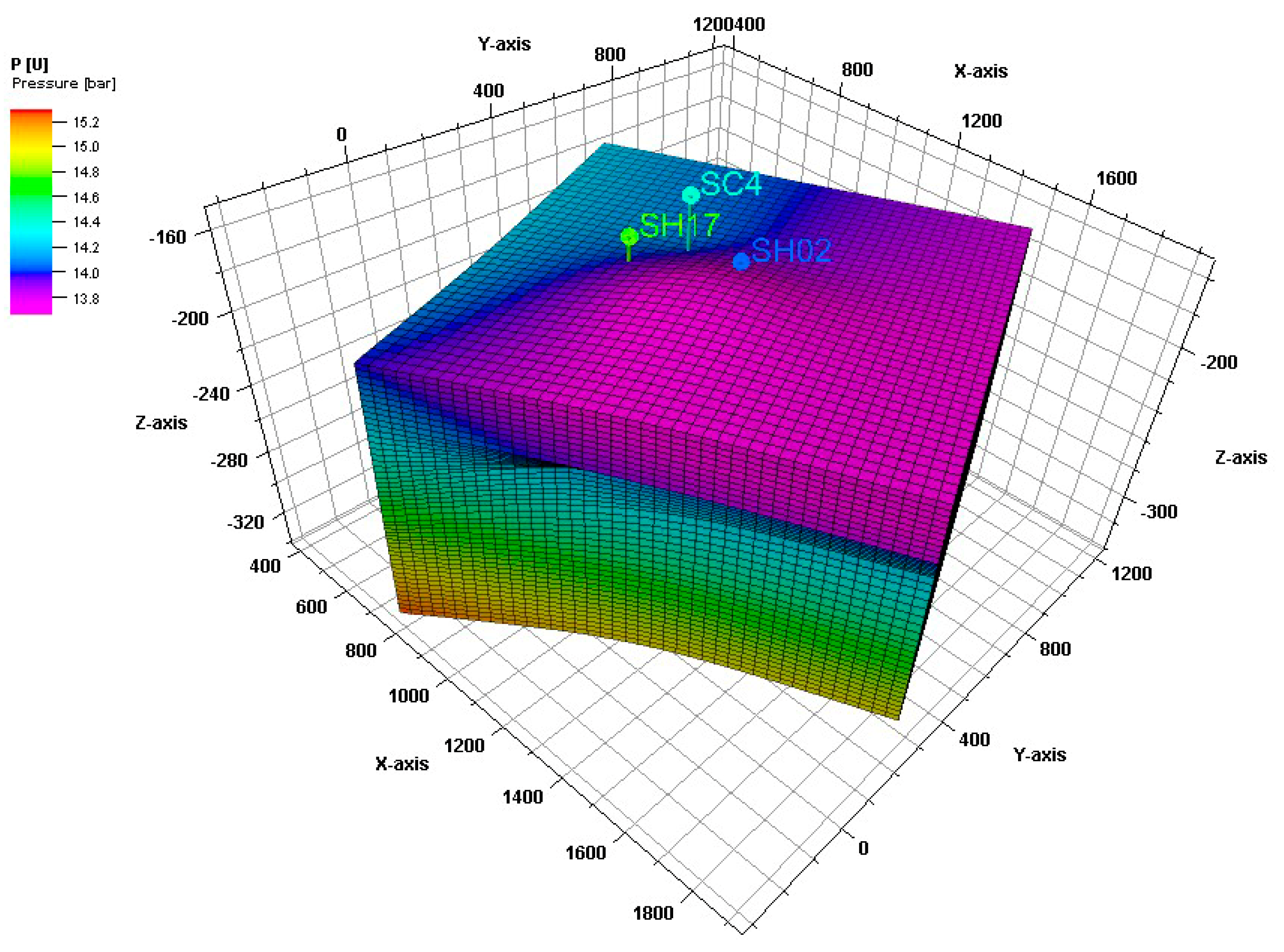
Based on the temperature–pressure gradient curve, the initial pressure at the bottom of the hydrate reservoir is calculated to be 15 MPa. According to the hydrate P-T equilibrium curve, the bottom of the hydrate reservoir in the model corresponds to the lower boundary of the hydrate stability zone, indicating that the entire hydrate layer remains in a stable phase prior to production disturbances.
Based on these geological findings, corrected temperature and pressure values are used for wells with available temperature and pressure data. For wells without such data, temperature and pressure curves are calculated using the geothermal and pressure gradients. The Kriging interpolation method is used to create temperature and pressure field models.
Figure 18 and
Figure 19 show the spatial distribution of the initial pressure and temperature fields in the model.
4.5. Hydrocarbon In-Place Modeling
The South China Sea is rich in natural gas hydrate resources, and accurate resource estimation is the basis for hydrate development and utilization. The 3D geological model can fully consider the spatial distribution of the reservoir sand body, porosity, permeability and saturation, and provide an accurate calculation method for calculating resources in the test production area.
According to the three-dimensional geological model of hydrate established above, because the reservoir belongs to the high porosity and low permeability reservoir, the lower limit of the effective reservoir is not applied to divide the effective reservoir. According to the model, the resource amount of hydrate in each layer in the test production area is 5.33 × 10
6 m
3 (
Figure 20,
Table 3).
5. Discussion
5.1. 3D Geological Modeling
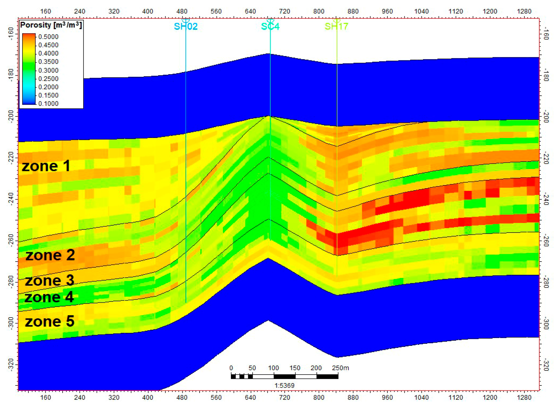
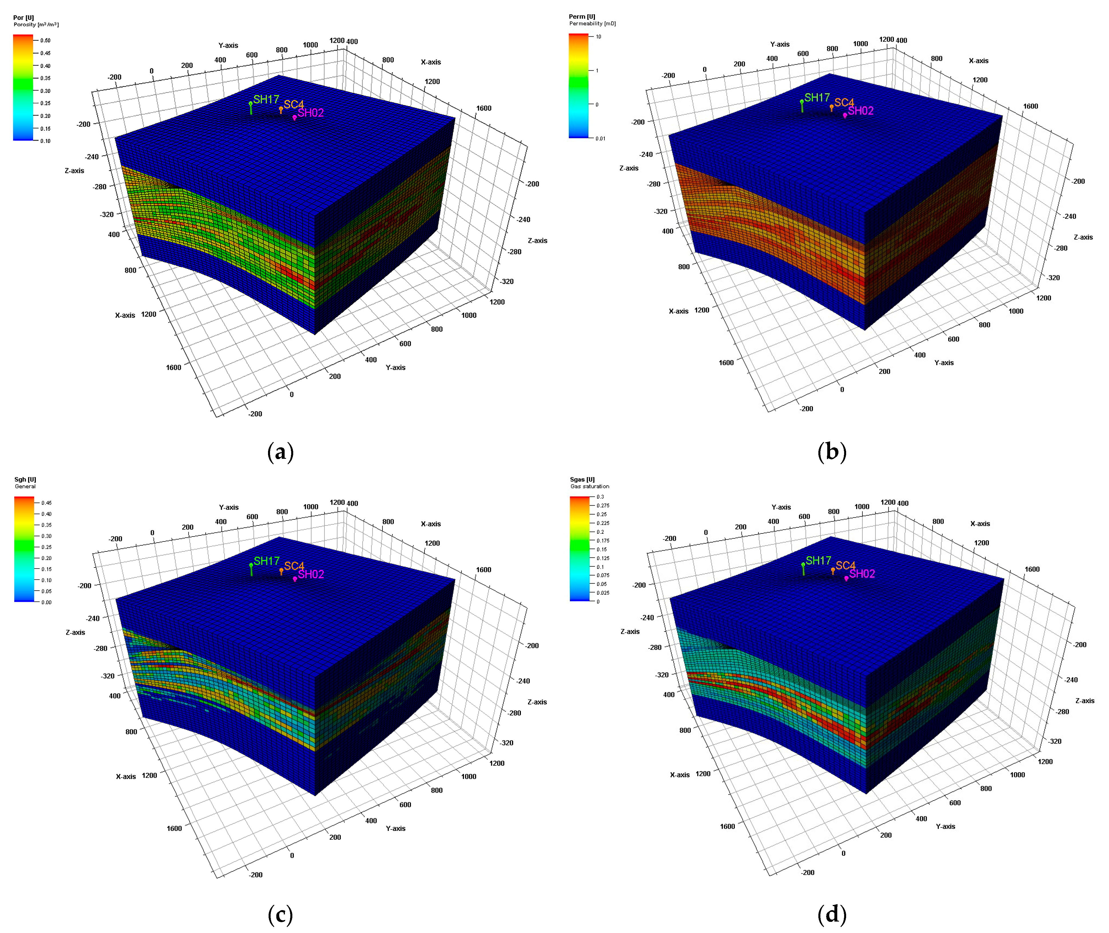
The SH02-SC4-SH17 well is located in the core area of the model. The formation framework model, the attribute model, and the temperature and pressure models are established based on the well data from the three wells and the regional seismic data. According to the geological model simulation analysis, the reservoir as a whole has high porosity and extremely low permeability, and the reservoir is highly heterogeneous, which is mainly reflected in the planar and longitudinal variations (
Figure 21).
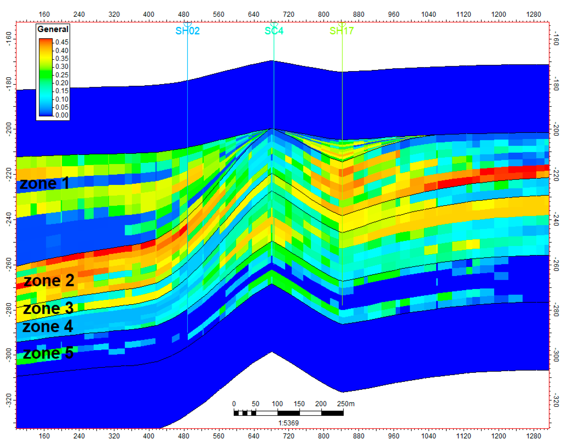
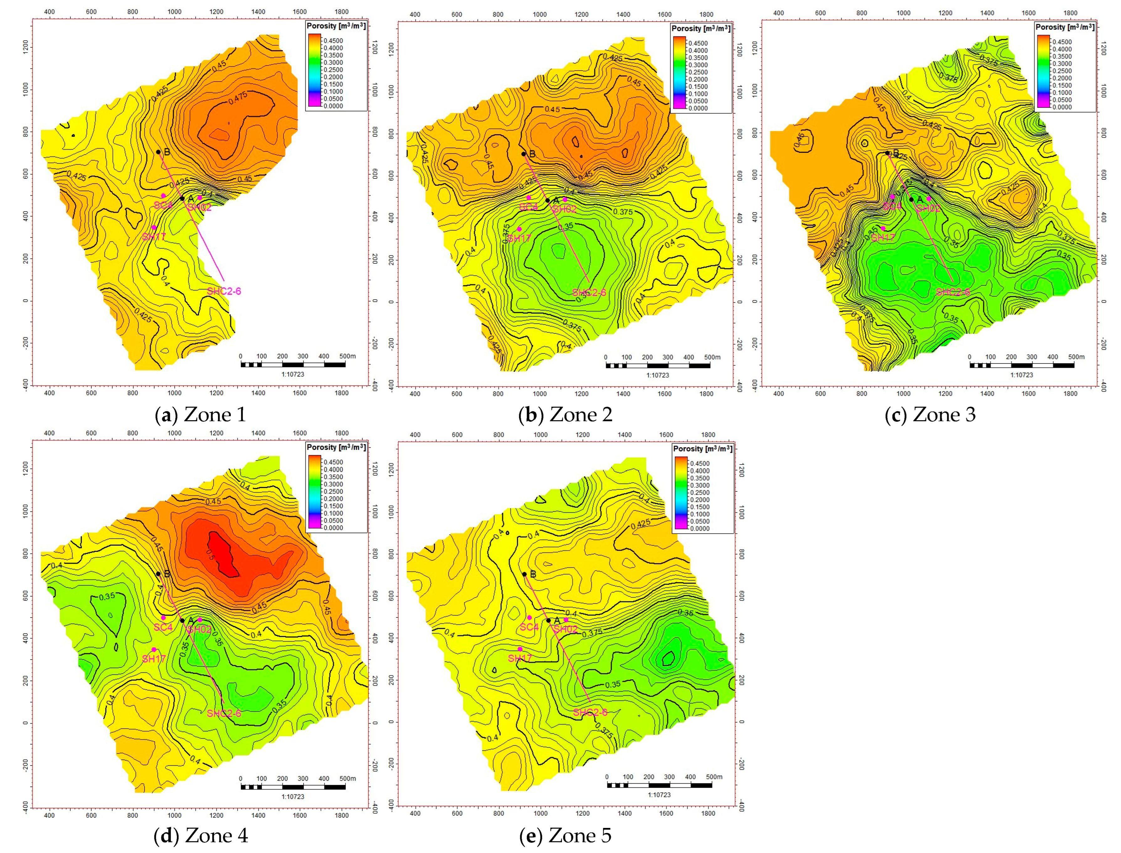
3D porosity model. Toward drill hole SH02-SC4-SH17, the porosity model goes from high to low and then to high, and a high hole interval appears in Zone 4 near drill hole SH17.
Permeability model 3D model. The whole reservoir has very low permeability. Permeability improves from top to bottom, and Zone 5 exhibits high permeability.
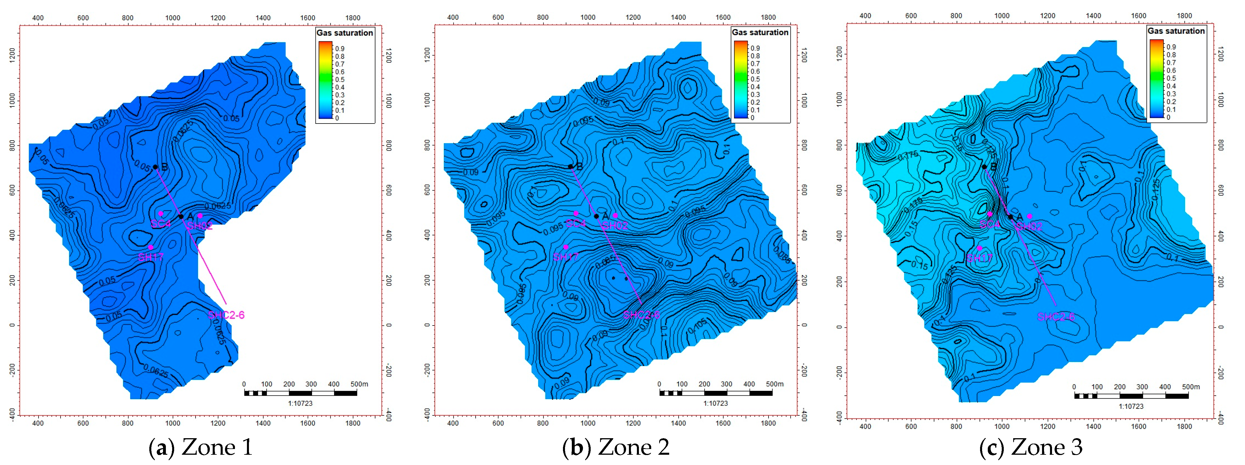
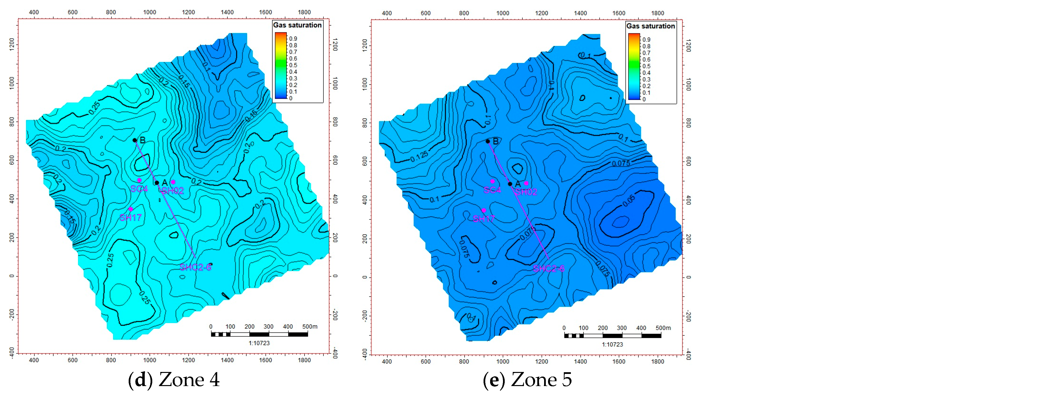
3D model. The gas-bearing interval is mainly Zone 1 to Zone 5, and Zone 4 has high gas saturation. In the three-dimensional hydrate saturation model, strong heterogeneity is observed. Zone 2 exhibits the highest hydrate saturation, characterized by a distribution pattern where saturation levels are higher on both sides and lower in the center.
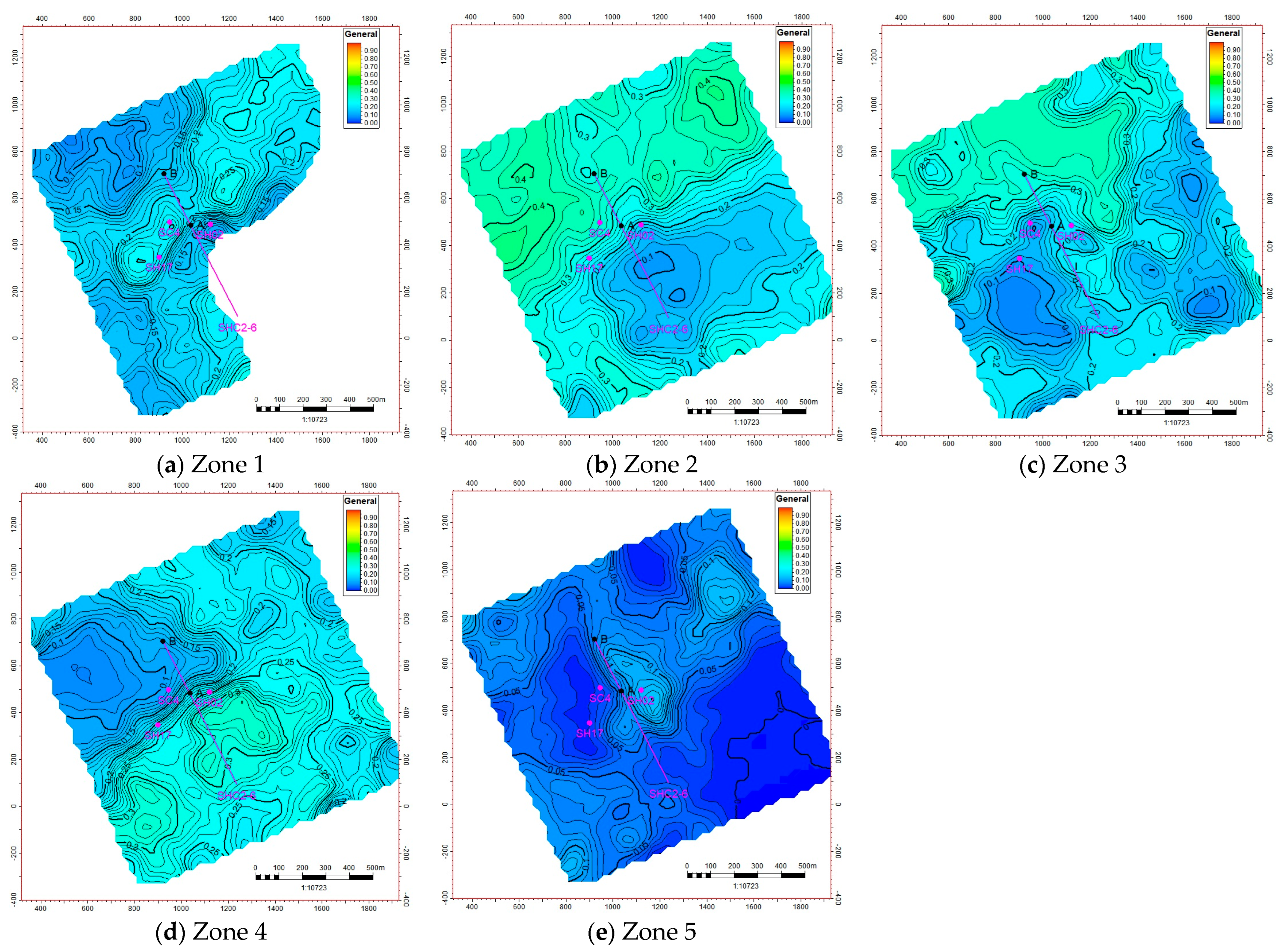
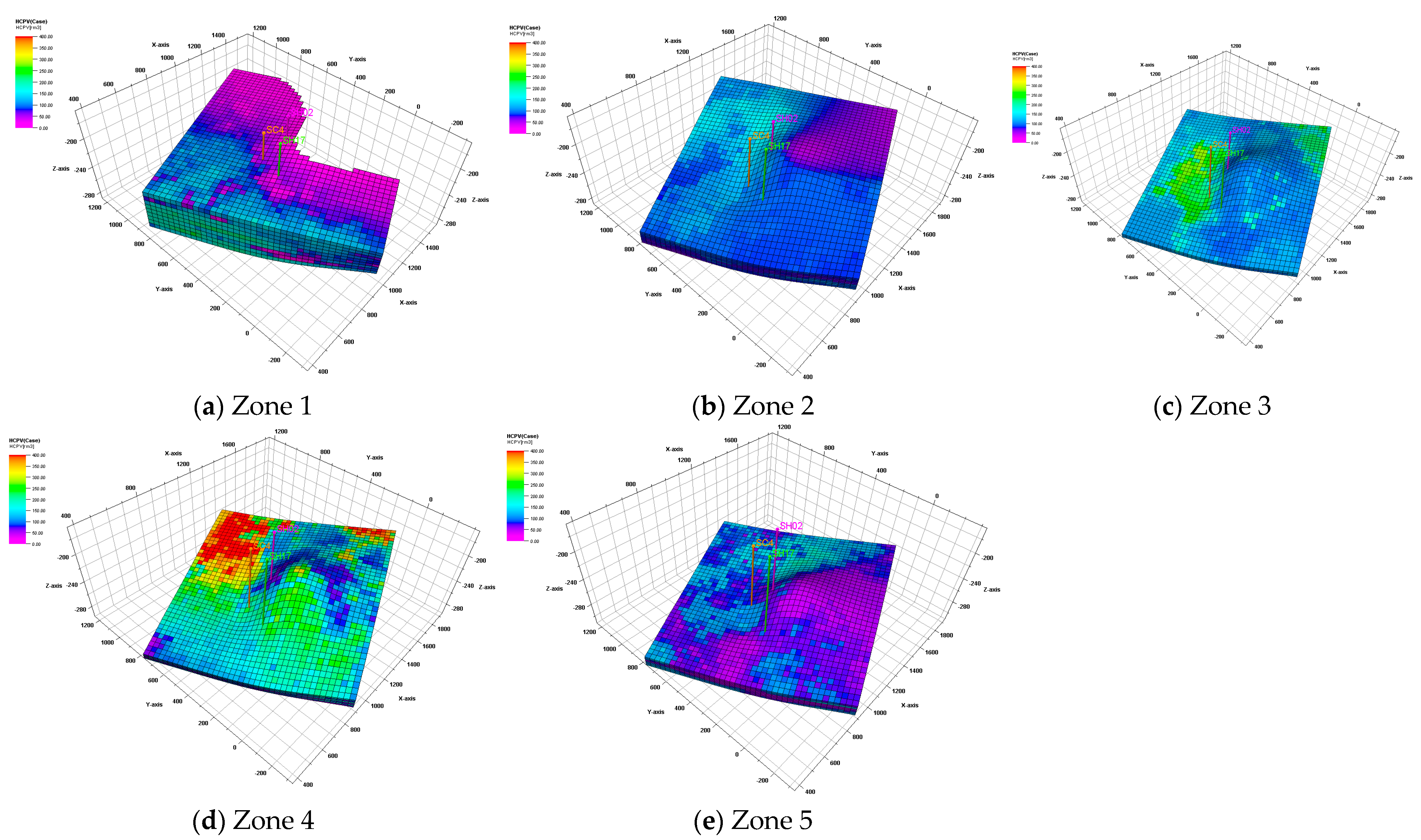
Overall, except for the correlation between porosity and saturation, the distribution of resource quantity and thickness is closer. The thickness of Zone 1 is missing, the thickness of Zone 3 is thin, and the resource quantity is relatively small, while the thicknesses of Zone 2, Zone 4, and Zone 5 are large, and the resource quantity is also large.
5.2. Uncertainty Analysis
This geological modeling exercise created a prototype model based on seismic, well logging, and other data for several wells, and reserves were calculated. Because of the small amount of data, certain uncertainties exist. The main uncertainties are as follows.
Structural model uncertainty arises mainly from seismic interpretation, velocity model, stratigraphic correlation, and well depth correction.
The attribute model uncertainty is mainly reflected in the uncertainty of logging interpretation. Porosity model uncertainty analysis mainly includes uncertainty in porosity interpretation, porosity variation function uncertainty, and seed number uncertainty. There are also uncertainties in saturation interpretation and permeability interpretation.
Uncertainty in resource calculation is mainly caused by calculation parameters in addition to porosity and saturation. The volume coefficient is not fully analyzed according to PVT test, which also causes uncertainty in resource quantity.
6. Conclusions
There are three vertical wells and one horizontal well in the Shenhu hydrate test production area in the South China Sea. At present, publicly available data cover only part of the three vertical wells. Wells SH02, SC4, and SH17 are located in the core area of the model. Based on well data from these three wells and regional seismic data, a stratigraphic framework model, a property model, and temperature and pressure models were constructed. Utilizing the three-dimensional heterogeneous geological model, the resource volume of the test production area was estimated, providing a solid geological foundation for natural gas hydrate production research.
- (1)
According to the simulation analysis of the geological model, the reservoir is characterized by high porosity and ultra-low permeability. Along the direction of wells SH02, SC4, and SH17, the porosity model varies from high to low and then back to high, with a high porosity section appearing near well SH17 in Zone 4. Permeability improves from top to bottom, with Zone 5 showing relatively higher permeability.
- (2)
The hydrate saturation model demonstrates strong heterogeneity. Zone 2 has the highest hydrate saturation, showing a trend of high saturation on both sides and lower saturation in the middle.
- (3)
The test production area has well developed faults. The first test production well, SHSC4, located in the central part, experiences a fault break in the upper hydrate layer, Horizon 1. Zones 1 to 3 have relatively high resistivity but low gas saturation, while Zone 4 has relatively high resistivity and high gas saturation (above 0.28), making it the primary target in the area.
- (4)
According to the model calculations, the total hydrate resource volume in the test production area is estimated at 5.33 × 10⁶ rm3. The resource volume is closely related to porosity and saturation, but is more strongly influenced by thickness. The thickness of Zone 1 is partially missing, and Zone 3 is relatively thin, resulting in a lower resource volume. In contrast, Zones 2, 4, and 5 are thicker, leading to relatively larger resource volumes.
Author Contributions
Literature search, L.M.; study design, L.M.; data analysis, L.M. and D.L.; data interpretation, L.M. and D.L.; writing—original draft preparation, L.M.; writing—review and editing, L.M., D.L., H.L., and S.W.; supervision, H.L., Y.Z., and S.W.; project administration, H.L. and S.W.; funding acquisition, H.L. and Y.Z. All authors have read and agreed to the published version of the manuscript.
Funding
This study was funded by project DD20221703 from the China Geological Survey.
Data Availability Statement
The authors will make the raw data supporting the conclusions of this article available upon request.
Conflicts of Interest
Author Shipeng Wei was employed by the company CNPC Offshore Engineering Company Ltd. The remaining authors declare that the research was conducted in the absence of any commercial or financial relationships that could be construed as a potential conflict of interest.
References
- Boswell, R.; Collett, T. Current perspectives on gas hydrate resources. Energy Environ. Sci. 2011, 4, 1206–1215. [Google Scholar]
- You, K.; Flemings, P.B.; Malinverno, A.; Collett, T.; Darnell, K. Mechanisms of methane hydrate formation in geological systems. Rev. Geophys. 2019, 57, 1146–1196. [Google Scholar]
- Wu, N.; Li, Y.; Wan, Y.; Sun, J.; Huang, L.; Mao, P. Prospect of the theory and technology system for increasing the production of natural gas hydrate in the sea area. Nat. Gas Ind. 2020, 40, 100–115. [Google Scholar]
- Beaudoin, Y.C.; Waite, W.; Boswell, R.; Dallimore, S.R. Frozen Heat: A UNEP Global Outlook on Methane Gas Hydrates; Tech. Rep.; United Nations Environment Programme; GRID: Arendal, Norway, 2014. [Google Scholar]
- He, J.; Zhong, C.; Yao, Y.; Yan, P.; Wang, Y.; Wan, Z.; Guan, J.; Zhang, J. Exploration and trial mining of natural gas hydrate in the northern part of South China Sea and research progress and exploration prospect. Mar. Geol. Front. 2020, 36, 1–14. [Google Scholar]
- Makogon, Y.F.; Holditch, S.A.; Makogon, T.Y. Natural gas hydrates—A potential energy source for the 21st century. J. Pet. Sci. Eng. 2007, 56, 14–31. [Google Scholar] [CrossRef]
- Seol, J.; Lee, H. Natural gas hydrate as a potential energy resource: From occurrence to production. Korean J. Chem. Eng. 2013, 30, 771–786. [Google Scholar] [CrossRef]
- Musakaey, N.G.; Khasanov, M.K.; Borodin, S.L. The mathematical model of the gas hydrate deposit development in permafrost. Int. J. Heat Mass Transf. 2018, 118, 455–461. [Google Scholar]
- Dallimore, S.R.; Collett, T.S.; Taylor, A.E.; Uchida, T.; Weber, M.; Chandra, A.; Mroz, T.H.; Caddel, E.M.; Inoue, T. Scientific results from the Mallik 2002 gas hydrate production research well program, Mackenzie Delta, northwest territories, Canada: Preface. Nat. Resour. Canada 2005, 585, 140. [Google Scholar]
- Yamamoto, K.; Dallimore, S. Aurora-JOGMEC-NRCan Mallik 2006–2008 gas hydrate research project progress. Nat. Gas Oil. 2008, 3, 285–4541. [Google Scholar]
- Numasawa, M.; Dallimore, S.R.; Yamamoto, K.; Yasuda, M.; Imasato, Y.; Mizuta, T.; Kurihara, M.; Masuda, Y.; Fujii, T.; Fujii, K.; et al. Objectives and operation overview of the JOGMEC/NRCan/Aurora Mallik gas hydrate production test. In Proceedings of the 6th International Conference on Gas Hydrates, Vancouver, BC, Canada, 6–10 July 2008. [Google Scholar]
- Yamamoto, K.; Terao, Y.; Fujii, T.; Ikawa, T.; Seki, M.; Matsuzawa, M.; Kanno, T. Operational overview of the first offshore production test of methane hydrates in the Eastern Nankai Trough. In Proceedings of the Offshore Technology Conference, Houston, TX, USA, 5–8 May 2014. [Google Scholar]
- Yamamoto, K.; Wang, X.X.; Tamaki, M.; Suzuki, K. The second offshore production of methane hydrate in the Nankai Trough and gas production behavior from a heterogeneous methane hydrate reservoir. RSC Adv. 2019, 9, 25987–26013. [Google Scholar] [CrossRef]
- Li, J.F.; Ye, J.L.; Qin, X.W.; Qiu, H.J.; Wu, N.Y.; Lu, H.L.; Xie, W.W.; Lu, J.A.; Peng, F.; Xu, Z.Q.; et al. The first offshore natural gas hydrate production test in South China Sea. China Geol. 2018, 1, 5–16. [Google Scholar] [CrossRef]
- Ye, J.L.; Qin, X.W.; Xie, W.W.; Lv, H.L.; Ma, B.J.; Qiu, H.J.; Liang, J.Q.; Lu, J.A.; Kuang, Z.G.; Lu, C.; et al. Main progress of the second gas hydrate trial production in the South China Sea. Geol. China 2020, 47, 557–568. [Google Scholar]
- Yu, T.; Guan, G.Q.; Abudula, A.; Wang, D. 3D investigation of the effects of multiple-well systems on methane hydrate production in a low-permeability reservoir. J. Nat. Gas Sci. Eng. 2020, 76, 103213. [Google Scholar] [CrossRef]
- Chen, C.Y.; Yu, C.Y.; Lv, T.; Li, X.S.; Zhang, Y.; Xu, L.X. Numerical simulation of vertical well network depressurization for natural gas hydrate reservoirs in the northern part of South China Sea. Nat. Gas Ind. 2020, 40, 177–185. [Google Scholar]
- Li, S.X.; Yu, X.; Li, S.; Li, Q.; Pang, W. Prediction of gas production of Shenhu hydrate reservoir by depressurization and its stimulation treatment. China Offshore Oil Gas 2020, 32, 122–127. [Google Scholar]
- Shang, S.; Gu, L.; Zhan, L.; Qiu, H.; Lu, H. Application of horizontal well to gas production from a hydrate reservoir with free gas and high irreducible water. J. Nat. Gas Sci. Eng. 2021, 94, 104102. [Google Scholar] [CrossRef]
- Mao, P.X.; Wu, N.Y.; Wan, Y.Z.; Chen, W.; Hu, G. Effects of perforation degree and deployment position of multilateral horizontal wells on gas production from inclined clay hydrate reservoirs. Mar. Geol. Quat. Geol. 2022, 42, 207–217. [Google Scholar]
- Ye, H.Y.; Wu, X.Z.; Li, D.Y.; Jiang, Y.J. Numerical simulation of productivity improvement of natural gas hydrate with various well types: Influence of branch parameters. J. Nat. Gas Sci. Eng. 2022, 103, 104630. [Google Scholar] [CrossRef]
- Lei, X.; Yao, Y.B.; Qin, X.W.; Lu, C.; Luo, W.J.; Wen, Z.A.; Yuan, X.H. Pore structure changes induced by hydrate dissociation: An example of the unconsolidated clayey-silty hydrate-bearing sediment reservoir in the South China Sea. Mar. Geol. 2022, 443, 106689. [Google Scholar] [CrossRef]
- Qin, X.W.; Lu, C.; Wang, P.K.; Liang, Q.Y. Hydrate phase transition and seepage mechanism during natural gas hydrate production tests in the South China Sea: A review and prospect. Geol. China 2022, 49, 749–769. [Google Scholar] [CrossRef]
- Fu, N.; Mi, L.J.; Zhang, G.C. Source rocks and origin of oil and gas in the northern Baiyun Depression of Pearl River Mouth Basin. Acta Petrol. Sin. 2007, 28, 32–38. [Google Scholar]
- Zhang, W.; Liang, J.Q.; Su, P.B.; Wei, J.G.; Sha, Z.B.; Lin, L.; Liang, J.; Huang, W. Migrating pathways of hydrocarbons and their controlling effects associated with high saturation gas hydrate in Shenhu area, northern South China Sea. Geol. China 2018, 45, 1–14. [Google Scholar]
- Zhang, W.; Liang, J.Q.; He, J.X.; Cong, X.R.; Su, P.B. Basic characteristics of mud-bottom pry/gas chimneys on the northern land slope of the South China Sea and their relationship with hydrocarbon and hydrate formation. Front. Mar. Geol. 2017, 33, 11–23. [Google Scholar]
- Su, P.B.; Liang, J.Q.; Peng, J.; Zhang, W.; Xu, J. Petroleum systems modeling on gas hydrate of the first experimental exploitation region in the Shenhu area, northern South China Sea. J. Asian Earth Sci. 2018, 168, 57–76. [Google Scholar] [CrossRef]
- Yang, C.Z.; Luo, K.W.; Liang, J.Q.; Lin, Z. Control of gas hydrate formation by shallow deep-water sedimentary bodies in the Shenhu Sea, northern South China Sea. Nat. Gas Ind. 2020, 40, 68–76. [Google Scholar]
- Su, P.B.; Liang, J.Q.; Fu, S.Y.; Lv, W.J.; Gong, Y.H. Exploration of geological conditions and genesis mode of gas hydrate formation in the northern part of South China Sea. China Geol. 2017, 44, 415–427. [Google Scholar]
- Yang, S.X.; Liang, J.Q.; Lu, J.A.; Qu, C. New understandings on the characteristics and controlling factors of gas hydrate reservoirs in the Shenhu area on the northern slope of the South China Sea. Earth Sci. Front. 2017, 24, 1–14. [Google Scholar]
- Xie, Y.F.; Lu, J.A.; Kuang, Z.G.; Kang, D.; Wang, T.; Cai, H. Well logging evaluation for three-phase zone with gas hydrate in the Shenhu area, South China Sea. Geoscience 2022, 36, 182–192. [Google Scholar]
- Wu, S.H. Reservoir Characterization and Modeling; Petroleum Industry Press: Beijing, China, 2010. [Google Scholar]
- Huang, T.; Zhang, Y.; Li, B.; Yang, W. Discussion on gas hydrate in Block Q of Qiongdongnan Basin. Offshore Oil 2018, 38, 1–6. [Google Scholar]
Figure 1.
Locations of wells for test production in 2017 and 2020. Point A denotes the target entry point of the horizontal well designated SHSC2-6, and AB represents the horizontal well section. (updated from Ye JL, 2020 [
15]).
Figure 1.
Locations of wells for test production in 2017 and 2020. Point A denotes the target entry point of the horizontal well designated SHSC2-6, and AB represents the horizontal well section. (updated from Ye JL, 2020 [
15]).
Figure 2.
Flowchart for modeling a gas hydrate reservoir.
Figure 2.
Flowchart for modeling a gas hydrate reservoir.
Figure 3.
Seismic characteristics of sections intersecting the SHSC-4 production test well (modified from Li JF et al. (2018) [
14]). Red lines represent the originally interpreted faults; purple lines indicate newly interpreted faults. (a) hydrate layer, (b) three-phase mixed layer, and (c) free gas layer.
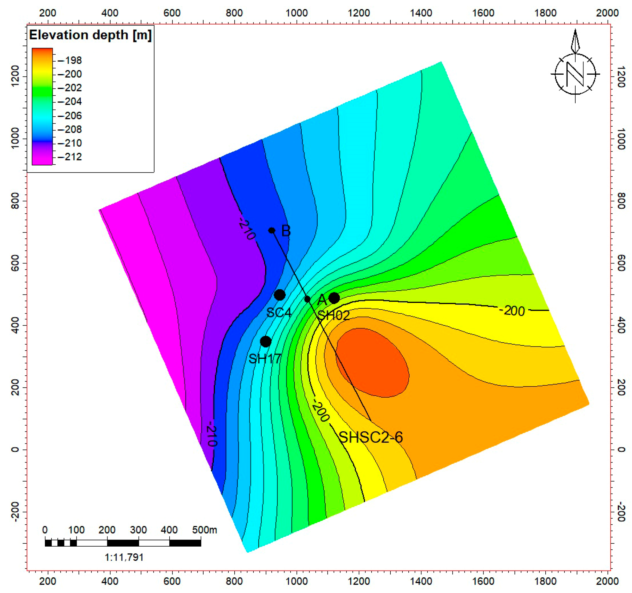
Figure 4.
Tectonic map of reservoir hydrate in Shenhu area. A and B represent the starting and end target points of the horizontal well, respectively.
Figure 4.
Tectonic map of reservoir hydrate in Shenhu area. A and B represent the starting and end target points of the horizontal well, respectively.
Figure 5.
Well logging results and hydrate distribution at sites SH02, SH12, and SHSC4, Shenhu Area, South China Sea.
Figure 5.
Well logging results and hydrate distribution at sites SH02, SH12, and SHSC4, Shenhu Area, South China Sea.
Figure 6.
Model boundaries and meshing settings. A and B represent the starting and end target points of the horizontal well, respectively.
Figure 6.
Model boundaries and meshing settings. A and B represent the starting and end target points of the horizontal well, respectively.
Figure 7.
Well profile and logging data for SH02, SC4, and SH17.
Figure 7.
Well profile and logging data for SH02, SC4, and SH17.
Figure 8.
Distribution of gas hydrate layer thickness across Zones 1–5.
Figure 8.
Distribution of gas hydrate layer thickness across Zones 1–5.
Figure 9.
Layer grid profile for wells SH02, SC4, and SH17.
Figure 9.
Layer grid profile for wells SH02, SC4, and SH17.
Figure 10.
Well log profile of porosity in the gas hydrate reservoir.
Figure 10.
Well log profile of porosity in the gas hydrate reservoir.
Figure 11.
Well log profile of permeability in the gas hydrate reservoir.
Figure 11.
Well log profile of permeability in the gas hydrate reservoir.
Figure 12.
Well log profile of gas saturation (Sgas) profile in the gas hydrate reservoir.
Figure 12.
Well log profile of gas saturation (Sgas) profile in the gas hydrate reservoir.
Figure 13.
Well log profile of hydrate saturation (Sgh) profile in the gas hydrate reservoir.
Figure 13.
Well log profile of hydrate saturation (Sgh) profile in the gas hydrate reservoir.
Figure 14.
Vertical distributions of porosity in the Shenhu area reservoir (Zones 1–5).
Figure 14.
Vertical distributions of porosity in the Shenhu area reservoir (Zones 1–5).
Figure 15.
Vertical distributions of permeability in the Shenhu area reservoir (Zones 1–5).
Figure 15.
Vertical distributions of permeability in the Shenhu area reservoir (Zones 1–5).
Figure 16.
Vertical distributions of gas saturation in the Shenhu area reservoir (Zones 1–5).
Figure 16.
Vertical distributions of gas saturation in the Shenhu area reservoir (Zones 1–5).
Figure 17.
Vertical distributions of hydrate saturation in the Shenhu area reservoir (Zones 1–5).
Figure 17.
Vertical distributions of hydrate saturation in the Shenhu area reservoir (Zones 1–5).
Figure 18.
Pressure distribution model for the Shenhu area gas hydrate reservoir.
Figure 18.
Pressure distribution model for the Shenhu area gas hydrate reservoir.
Figure 19.
Temperature distribution model for the Shenhu area gas hydrate reservoir.
Figure 19.
Temperature distribution model for the Shenhu area gas hydrate reservoir.
Figure 20.
Distribution of natural gas hydrate in Shenhu area (Zones 1–5).
Figure 20.
Distribution of natural gas hydrate in Shenhu area (Zones 1–5).
Figure 21.
(a–d) illustrate the characteristics of porosity, permeability, hydrate saturation, and gas saturation in the Shenhu Area gas hydrate reservoir.
Figure 21.
(a–d) illustrate the characteristics of porosity, permeability, hydrate saturation, and gas saturation in the Shenhu Area gas hydrate reservoir.
Table 1.
Geological parameters of wells SH02, SHSC-4, and SH17.
Table 1.
Geological parameters of wells SH02, SHSC-4, and SH17.
| Well Number | GMGS6-SH02 | SHSC-4 | GMGS5-SH17 |
|---|
| Reservoir | Hydrate layer | Mixed layer | Free gas layer | Hydrate layer | Mixed layer | Free gas layer | Hydrate layer | Mixed layer | Free gas layer |
| Depth (mbsf) | 207.8–253.4 | 253.4–278 | 278–297 | 201–236 | 236–251 | 251–278 | 205–252 | 252–272 | 272–286.4 |
| Thickness (m) | 45.6 | 24.6 | 19 | 35 | 15 | 27 | 47 | 20 | 14.4 |
| Porosity (%) | 37.3 | 34.6 | 34.7 | 35 | 33 | 32 | 46 | 48 | 0.22 |
| Permeability (mD) | 2.38 | 6.63 | 6.8 | 2.9 | 1.5 | 7.4 | 4.3 | 5.6 | 0.22 |
Water
saturation (%) | 69 | 75.1 | 92.7 | 66 | 52.6 | 92.2 | 66 | 71.2 | 90.4 |
| Gas saturation (%) | 0 | 13.2 | 7.3 | 0 | 16.4 | 7.8 | 0 | 14 | 9.6 |
Hydrate
saturation (%) | 31 | 11.7 | 0 | 34 | 31 | 0 | 36.6 | 14.8 | 0 |
Table 2.
Attribute table of each layer.
Table 2.
Attribute table of each layer.
| Zone | Porosity | Permeability (mD) | Sgas | Sgh |
|---|
| Min | Max | Mean | Min | Max | Mean | Min | Max | Mean | Min | Max | Mean |
|---|
| Zone 1 | 0.178 | 0.502 | 0.431 | 3.109 | 4.951 | 3.951 | 0 | 0.098 | 0.056 | 0 | 0.28 | 0.05 |
| Zone 2 | 0.335 | 0.492 | 0.408 | 1.738 | 4.825 | 3.591 | 0.069 | 0.112 | 0.094 | 0.08 | 0.43 | 0.27 |
| Zone 3 | 0.326 | 0.453 | 0.388 | 1.837 | 4.167 | 3.329 | 0.083 | 0.191 | 0.112 | 0.06 | 0.39 | 0.22 |
| Zone 4 | 0.305 | 0.523 | 0.406 | 1.871 | 6.048 | 3.91 | 0.06 | 0.3 | 0.206 | 0.07 | 0.34 | 0.22 |
| Zone 5 | 0.31 | 0.445 | 0.387 | 3.367 | 5.728 | 4.62 | 0.04 | 0.149 | 0.088 | 0 | 0.15 | 0.05 |
| Total | 0.178 | 0.523 | 0.404 | 1.738 | 6.048 | 3.88 | 0 | 0.3 | 0.111 | 0 | 0.43 | 0.162 |
Table 3.
Parameters for the estimation of the resources of gas hydrates in the Shenhu area.
Table 3.
Parameters for the estimation of the resources of gas hydrates in the Shenhu area.
| Zones | Bulk Volume
[×106 m3] | Net Volume
[×106 m3] | Pore Volume
[×106 m3] | HCPV Gas
[×106 m3] |
|---|
| Zone 1 | 23 | 23 | 10 | 0.71 |
| Zone 2 | 27 | 27 | 11 | 1.05 |
| Zone 3 | 11 | 11 | 4 | 0.44 |
| Zone 4 | 28 | 28 | 11 | 2.19 |
| Zone 5 | 26 | 26 | 10 | 0.94 |
| Total | 115 | 115 | 46 | 5.33 |
| Disclaimer/Publisher’s Note: The statements, opinions and data contained in all publications are solely those of the individual author(s) and contributor(s) and not of MDPI and/or the editor(s). MDPI and/or the editor(s) disclaim responsibility for any injury to people or property resulting from any ideas, methods, instructions or products referred to in the content. |
© 2025 by the authors. Licensee MDPI, Basel, Switzerland. This article is an open access article distributed under the terms and conditions of the Creative Commons Attribution (CC BY) license (https://creativecommons.org/licenses/by/4.0/).


