Abstract
The armor layer is one of the core components of flexible risers. It provides essential mechanical properties such as tensile strength, pressure resistance, and torsional performance, which are necessary for operation in complex marine environments. However, due to the significant disparity between the cross-sectional dimensions of the armor wires and the overall riser size, severe computational costs are often incurred when a finite element (FE) model is employed for the performance analysis of an armor layer. To address this, an asymptotic homogenization method for flexible risers is established in the present study. In this method, the armor wires, modeled as beam elements, are equivalent to an anisotropic shell structure, and the equivalent elastic properties of the armor layer are obtained with unit-cell analysis. These properties are then used for the overall analysis of the flexible riser’s armor layer response, without considering the specific characteristics of the steel wires, thereby improving the efficiency of the performance analysis. The effectiveness of the proposed method is verified in a numerical example based on a comparison with a finite element (FE) model. Moreover, the effect of the unit cell size is investigated by introducing a size factor. A significant size effect is observed, unlike in the truss-based unit cell, for which an explanation based on the stiffness coefficient is given. The proposed method offers a new technique for efficient performance analysis of the armor layer of flexible risers.
1. Introduction
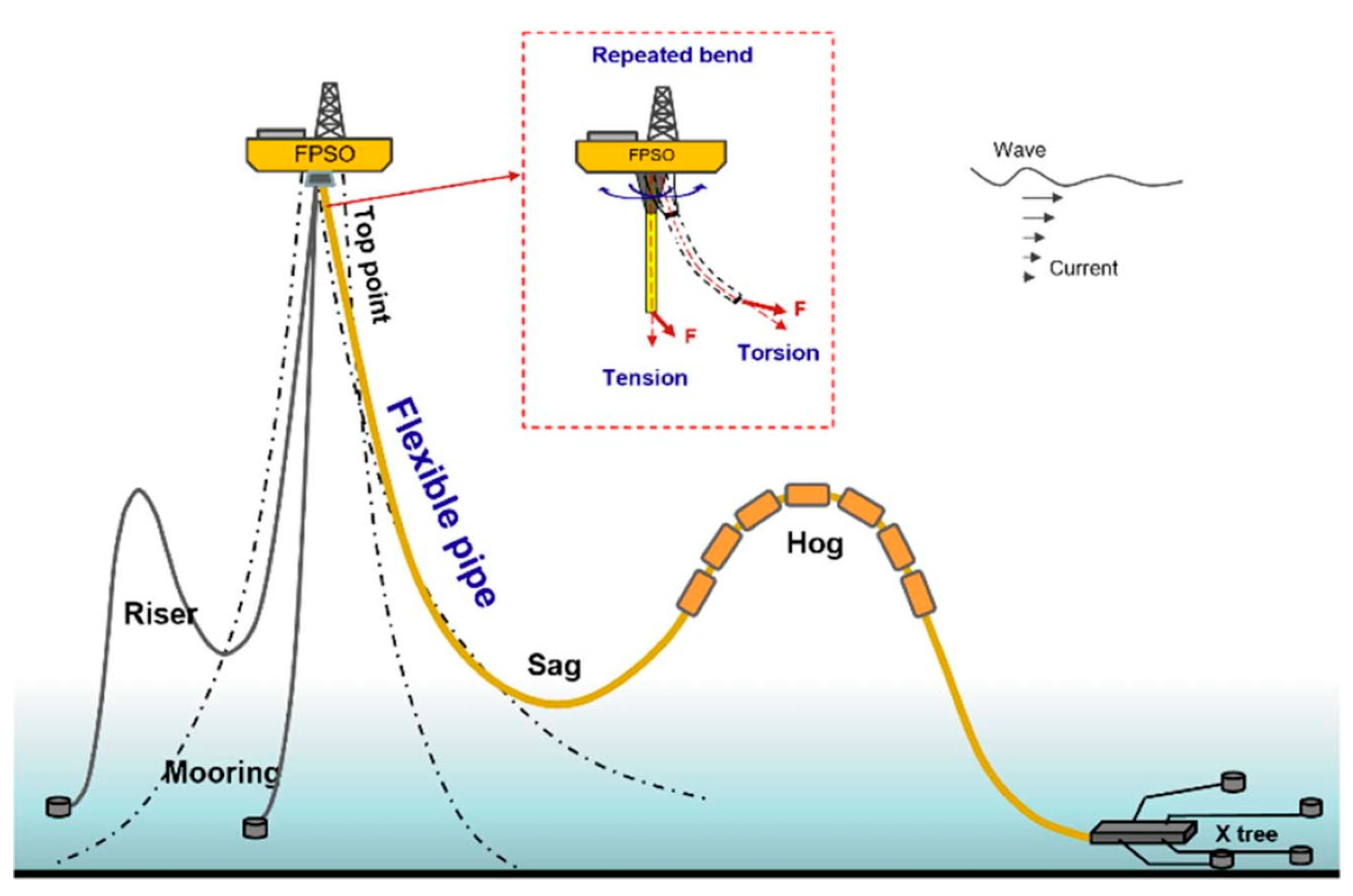
Flexible risers [1,2] play a crucial role in offshore oil and gas development, especially in deep-water and ultra-deep-water environments (cf. Figure 1). Their unique helical winding structure [3] provides the necessary tensile strength to withstand their own weight while maintaining a low bending stiffness [4]. This high flexibility allows them to endure the complex loading conditions of marine environments, such as wave and current loads [5]. Compared with traditional rigid risers, flexible risers are easier to install and maintain. Their ability to be coiled enables pre-production and testing on land, followed by transport to the designated site by ship, significantly reducing installation time and costs. Currently, flexible risers are suitable for fixed platforms, Floating Production Storage and Offloading (FPSO) units, and semi-submersible drilling rigs. Their dynamic adaptability makes them the ideal choice for connecting subsea oil and gas resources to floating production facilities [6]. As offshore development progresses into deeper and more distant waters, the importance of flexible risers will become increasingly evident, solidifying their status as an indispensable technology in offshore energy development.

Figure 1.
Flexible riser in operation.
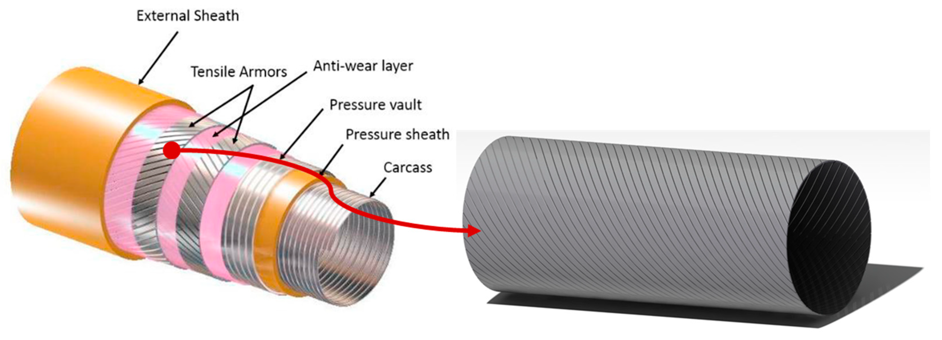
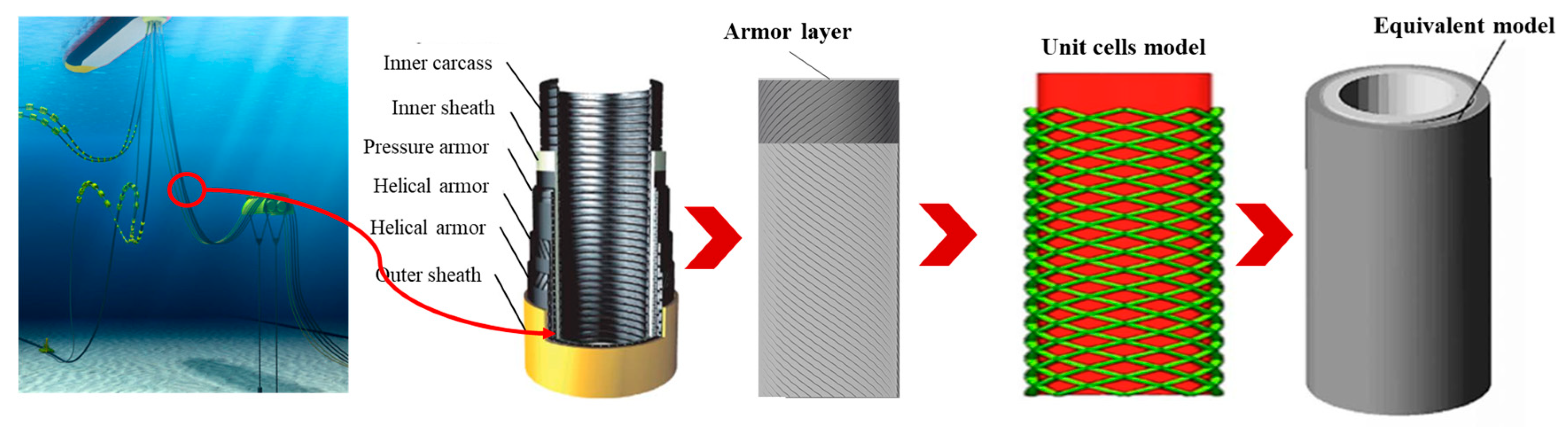
As depicted in Figure 2, the armor layer is a critical component of flexible risers. It provides the necessary tensile strength, pressure resistance, and torsional performance required during the service life of flexible risers while preventing external damage and extending their lifespan. Therefore, studying the mechanical properties of the armor layer is crucial to ensuring the safe and reliable operation of flexible risers. Bahtui et al. [7] conducted a detailed finite element analysis of unbonded flexible risers, comparing numerical results with analytical solutions for various load cases. The strong agreement between numerical and analytical results validates the numerical model for benchmark solutions. Liu et al. [8] used an unbonded flexible riser model and presented cases using theoretical and numerical methods for validation. They investigated the impact of the composite’s fiber volume fraction on the axial tensile stiffness and weight of the riser. Knapp [9] introduced a new element stiffness matrix for tension and torsion in cable-strengthening layers and derived the equilibrium equation, including geometric nonlinearity from large deformations. The experimental results matched well with those from the two different cable types. Subsequently, the multilayer structure of the flexible riser was simplified to a single-layer structure for calculating tension and torsion. Recently, the performance analysis of armor structures has been extended from single layers to double layers [10]. With the increase in water depth, the bending effects on the strengthening layer become significant. Therefore, Sævik and Thorsen [11] conducted theoretical research on the bending of strengthening layers. Anastasiadis et al. [12] examined metal-based unbonded flexible pipes under various axial tensile loads, focusing on the tensile armor wires inside the pipe end fitting to assess stress concentration factors. Zhang et al. [13] presented theoretical and numerical studies on the bending properties of unbonded flexible risers and the impacts of axisymmetric loads on bending behavior. Ren et al. [14] developed analytical and numerical models to predict unbonded flexible riser behavior under torsion. They found that the local bending and torsion of helical strips significantly influence torsional stiffness, though the stress related to bending and torsion is negligible. Gautam et al. [15] introduced a multiscale model using a combined analytical–computational approach to predict the torsional and flexural behavior of hybrid composite wires, investigating the role of over-braid structural parameters, pre-tension, and internal friction. The multiscale model’s behavior was found to be in good agreement with experimental observations.

Figure 2.
Flexible riser and characteristics of its armor layer.
However, the characteristic dimensions of the steel wires in the armor layer differ by several orders of magnitude from the overall dimensions of the flexible riser (cf. Figure 2). This significant disparity results in higher numerical costs when using detailed finite element models to analyze the armor layer’s response and assess the overall performance of the riser. To address this, multiscale analysis methods [16,17] have increasingly been applied in the analysis of marine cable structures. In flexible risers, the armor structure within a single pitch length can be considered a basic structural unit (i.e., a unit cell). When these unit cells are periodically arrayed, they form the armor layer of the entire riser structure. Analyzing this unit cell to obtain its equivalent elastic properties and then using these properties for the overall riser structure analysis, without considering the specific makeup of the armor layer, allow for computational costs to be significantly reduced.
Common multiscale analysis methods include the Representative Volume Element (RVE) method [18], the Multiple-scales Finite Element Method (MsFEM) [19,20], and the Asymptotic Homogenization (AH) method [21,22]. The RVE method provides a simple scheme to calculate the equivalent properties of a unit cell, but improper boundary condition selection may lead to significant misestimation of the equivalent properties [23]. In the MsFEM, the unit cell is regarded as a super-element. A numerical shape function is obtained via microscale analysis and then used for assembling the global stiffness matrix by traversing all the super-elements. However, a significant computational cost may be incurred when a large number of unit cells are involved in the structural analysis [24]. Compared with RVE and the MsFEM, in the Asymptotic Homogenization method, based on asymptotic expansion theory with a rigorous mathematical foundation, the unit-cell size is assumed to be infinitely small, making the specific microscopic equivalent solution independent of the unit-cell size. This method achieves complete decoupling between macro- and micro-analysis scales, allowing the macro-structure to be freely meshed, thus offering significant advantages in analyzing structures with many unit cells [25]. In the traditional implementation of the Asymptotic Homogenization method, it is necessary to derive the corresponding microscopic analysis solution format according to the specific type of unit cell, and the developed analysis code often lacks generality [26]. This limitation restricts the microscopic equivalent analysis of Asymptotic Homogenization to 2D planar elements. To address this, Cheng et al. [27] developed a new format for Asymptotic Homogenization (Novel Implementation of Asymptotic Homogenization, NIAH) based on the energy format proposed by Sigmund [28]. The NIAH method provides a generalized multiscale equivalent reduced-order analysis method for porous media, greatly broadening the applicability of the Asymptotic Homogenization method. Within this unified analysis framework, unit-cell types can be freely chosen, and even mixed types are allowed [29]. Many scholars have studied the equivalent analysis theory of one-dimensional periodic beam structures and two-dimensional periodic plate and shell structures with the NIAH method [30,31], extending the analysis from statics to heat conduction [32,33] and buckling [34].
As aforementioned, the armor layer provides flexible risers with critical protection against tension, compression, and torsion. However, as a typical periodic structure, the characteristic structural element (i.e., the representative volume element or unit cell) of the armor layer is much smaller than the overall length of a flexible riser, resulting in a large number of unit cells within the structure. Conducting structural analysis by constructing a finite element model that includes all unit cell features would incur a significant computational cost. Therefore, in this study, by leveraging the periodic nature of the armor layer, an equivalent analysis is developed based on the NIAH method. The equivalent elastic properties of the armor layer are predicted; then, the structural responses of the flexible riser are calculated efficiently by using the obtained equivalent properties. The rest of this paper is organized as follows: In Section 2, the theory underlying the traditional AH method is introduced. In Section 3 and Section 4, a novel implementation of the AH method for shell structures is established, and the detailed implementation procedure is then presented. In Section 5, the proposed NIAH method is verified by using typical loading conditions that are encountered in practical engineering applications, i.e., tension, torsion, and bending; additionally, the influence of the geometry size of the micro-structure of the armor layer on the results of the structural analysis is also considered. Finally, we report our conclusions at the end of this paper. The proposed method holds significant importance for enhancing flexible riser analysis efficiency in offshore engineering, reducing new-product development costs, and shortening the development cycle.
2. Asymptotic Homogenization Method
To address the computational costs arising from the significant size disparity between the steel wires in the armor layer and the overall dimensions of the flexible riser, in this study, we establish an Asymptotic Homogenization (AH) method for armor layer structures. A representative volume element (RVE), i.e., a unit cell of the flexible riser is selected for microscopic analysis.
As shown in Figure 3, in the AH method, first, the unit cell is extracted. Then, a micro-analysis under periodic boundary conditions is performed to obtain the equivalent properties (e.g., tension, shear, bending, etc.) of the unit cell. It can be considered that the calculated equivalent properties can provide a comprehensive description of the mechanical behavior of the armor layer. Therefore, a homogeneous layer with these equivalent properties can be used to estimate the response of a flexible riser based on macro-analysis. Differently from the classical AH method using solid elements, in the present study, the double-layer armor within the unit cell is modeled as helically wound Euler–Bernoulli beams, and the armor layer is equivalent to a Reissner–Mindlin shell structure with anisotropic properties. This shell model possesses the same tensile, bending, and torsional properties as the armor layer’s RVE. Thus, the material properties of this shell model can be used to conduct a mechanical performance analysis of the entire flexible riser structure without considering the specific configuration of the armor wires, significantly reducing the computational cost of analyzing the armor layer structure of the flexible riser. Notably, in the proposed AH method, we match the slenderness ratio of the Euler–Bernoulli beam, since the radius of steel wires is much smaller than their length. Additionally, considering the ratio between the thickness of the armor layer and the radius of the flexible riser, a medium shell element based on Reissner–Mindlin theory is employed for macroscale analysis. Moreover, in the present study, we assume that the material of the steel wires within the armor layer is linear and homogeneous, and a small deformation assumption is adopted. Simultaneously, we do not take into account the friction among steel wires.
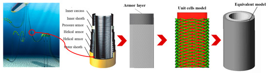
Figure 3.
Homogenization method for armor layer of flexible riser.
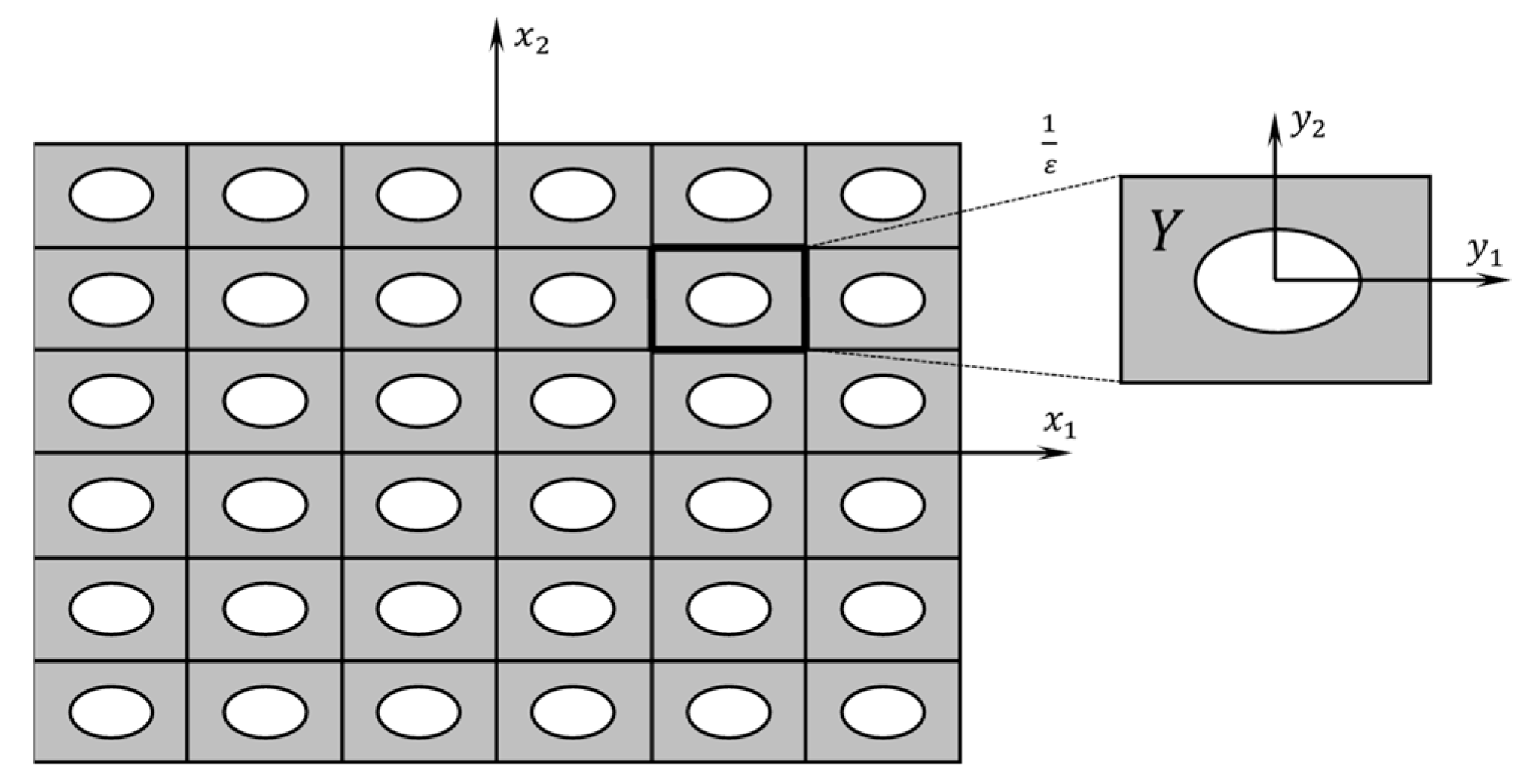
In the following, the basic theory of asymptotic homogenization method is briefly introduced; please refer to Hassani and Hinton (1998) [21] for more details of the asymptotic homogenization method. As shown in Figure 4, an arbitrary response function is defined over the macrodomain , which is composed of a large number of periodic unit cells. To enable an asymptotic expansion for , a small parameter is introduced. Then, the micro-coordinate considering the periodicity of the unit cells can be established as:
where is the periodic microdomain of the unit cell.
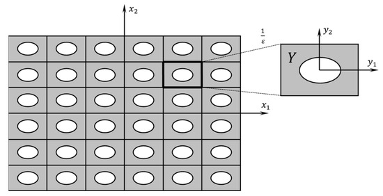
Figure 4.
The unit cell, as described for the dual-scale coordinates used in the NIAH method.
The derivative of with respect to can be written as:
According to the asymptotic homogenization theory [21], displacement can be expressed with dual-scale coordinates and then expanded with respect to parameter . Then,
By substituting Equation (3) into the virtual work equation, one can obtain
where is the material domain, whose boundary is denoted by ; is an arbitrary function satisfying the specified displacement boundary conditions, whose derivatives can be expanded according to Equation (2); and and are the components of the body force and traction force applied on the domain boundary, respectively. By comparing items with the same power coefficient about in Equation (4), one can obtain
An arbitrary function is integrated as:
where is the volume of the unit cell. When is quite small, by applying the integration operator in Equation (8) to Equations (5)–(7), one can obtain:
respectively, where is the vector of characteristic displacement, is the elastic modulus of the solid material, and is the equivalent elastic tensor of the armor layer unit cell.
The equivalent elastic tensor is given in Equation (11); however, a few difficulties are encountered when it is used for practical implementation (cf. Cai et al. (2014) [22]). Therefore, an energy-based formula is derived below. By considering the symmetry and taking the arbitrary function v in Equation (10) as , Equation (10) can be rewritten as:
where is the displacement of the unit cell of the armor layer with a unit strain field. By substituting Equation (12) into Equation (11), the equivalent elastic tensor of a unit cell in the armor layer can be calculated as:
3. Novel Implementation of Asymptotic Homogenization (NIAH) with Finite Element Method
The homogenization of the armor layer in a flexible riser can be implemented by using Equation (11) or (13). However, determining the characteristic displacement at the microscale typically requires complex derivations and specialized finite element (FE) operations. Furthermore, such custom-built programs often lack versatility and necessitate substantial modifications for different unit-cell geometries. The implementation using the classical AH method is challenging and time-consuming. To address these challenges, a novel implementation of the Asymptotic Homogenization (AH) method combining ANSYS 18.0 is proposed below.
The characteristic displacement, , can be obtained by solving Equation (10) in the domain of unit cells; then, the corresponding FE equilibrium equation can be written as:
where K is the stiffness matrix of the micro-structure of unit cells, f is the loading vector, B is the strain–displacement matrix, and E is the elastic matrix of the base material of the unit cells. We can make the following transformation:
where denotes the unit strain matrix and has the same order as . The displacement matrix is determined by the unit strain . Please note that the form of is not unique and that all the displacements that induce the unit cell to produce unit strain can be adopted. The specific form of with respect to a cylindrical shell structure is discussed in Section 4. Then, the in Equation (17) can be obtained by multiplying the total stiffness matrix K by the displacement matrix . This process can also be straightforwardly achieved with static analysis in commercial FE software for a given nodal displacement .
For clarity, Equation (14) needs to be solved under periodic boundary conditions and can be rewritten as follows:
where , , and . The variables with the top sign denote the ones with periodic boundary conditions.
As evident from Equations (17) and (18), the characteristic displacement of the unit cell can be regarded as the deformation caused by a unit strain field under periodic boundary conditions. The characteristic displacement can be solved with static analysis. By taking into account the change in parameter symbols in Equation (18), Equation (13) can be rewritten in the following FE form:
where is the finite element stiffness matrix of the microscopic unit-cell structure, and and denote the elements’ displacement matrices corresponding to and , respectively. By taking the characteristic displacement as specified nodal displacements within the unit cell, one can obtain the nodal force matrix with periodic boundary conditions similar to the solving process of above. Therefore, Equation (19) can be rewritten as:
Equation (20) is the method of novel implementation of asymptotic homogenization with FE, with which one can calculate the equivalent elastic matrix of the armor layer unit cell. From Equation (20), has the energy dimension and is thus regarded as the average of the strain energy generated by some specified strain field within the unit cell.
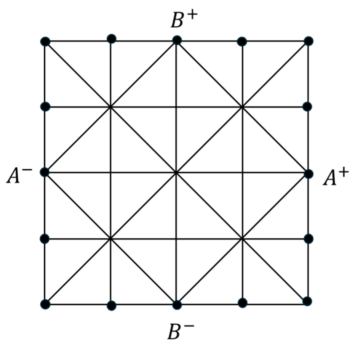
From Equations (18)–(20), it is known that a periodic boundary condition is critical for calculating the equivalent performance of a unit cell. Moreover, the periodic boundary condition can be regarded as a multi-freedom constraint problem. As shown in Figure 5, this requires that the displacements on point pairs () and () satisfy the following relations:
where and are the points on the left and right edges, respectively, and and are those on the upper and lower edges, respectively. For more details, please refer to Tian et al. [35].
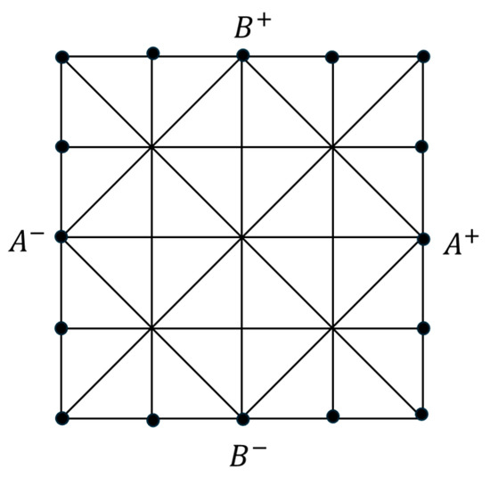
Figure 5.
Illustration of periodic boundary conditions in micro-analysis.
In the above analysis, every variable is solved, and the equivalent elastic matrix of the unit cell can be obtained with simple matrix multiplications. NIAH can simplify complex mathematical derivations and programming processes, fully taking advantage of the rich elemental libraries and modeling tools that commercial FE software tools provide. Thus, the difficulty and workload of modeling and programming in the execution of the AH method are significantly reduced.
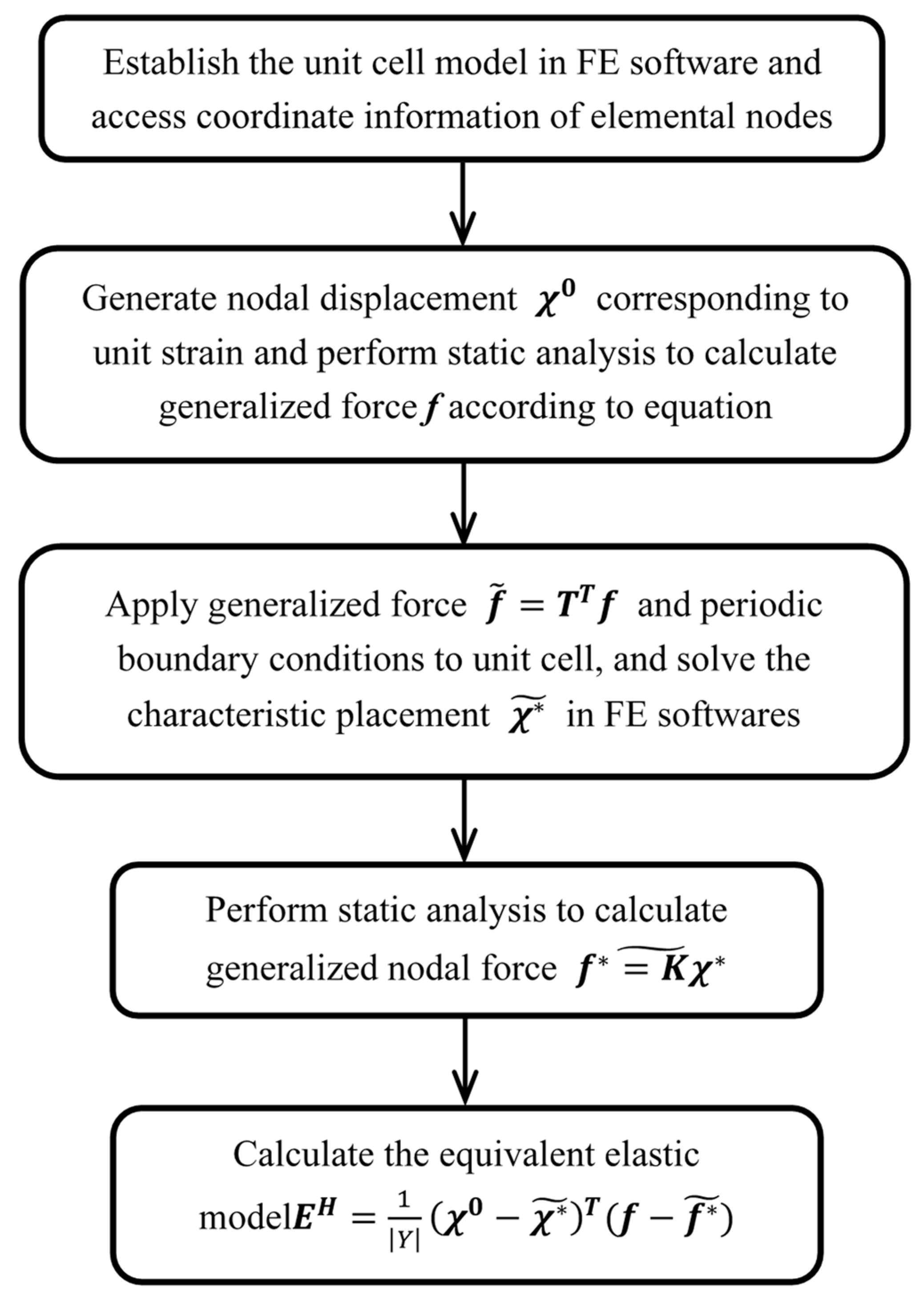
The following are the execution steps necessary to calculate the equivalent elastic modulus of the armor layer unit cell by using the NIAH method:
(1) According to the material configurations, select the micro-structure of the unit-cell model, and calculate the nodal displacement deduced from the unit strain of the unit cell. The selected displacement functions may not be unique.
(2) After performing modeling in commercial FE software, applying the nodal displacement to the nodes of the unit cell of the armor layer, and performing a static analysis, obtain the generalized characteristic force with Equation (17).
(3) By applying the generalized characteristic force and periodic boundary conditions to the unit cell, the characteristic displacement can be obtained with the static analysis in the FE software.
(4) By applying the characteristic displacement obtained above to the unit cell and performing a static analysis, obtain the corresponding nodal force .
(5) Then, calculate the equivalent elastic matrix according to Equation (20).
The calculation process is shown in Figure 6. Since the unit-cell solving steps in the above calculation process are carried out with FE software, this method is applicable for more complex and different forms of unit-cell configurations, such as 3D unit cells, plate and shell unit cells, and stiffened skin unit cells. For different forms of unit cells, one simply selects the appropriate finite element to model and calculate the homogenized material properties, which significantly simplifies homogenization analyses with complex unit-cell configurations.
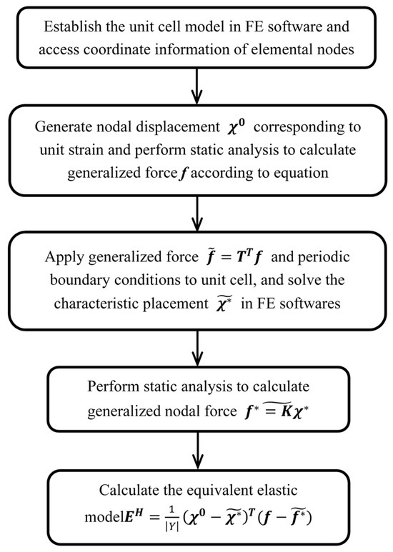
Figure 6.
Flowchart of micro-analysis of the proposed NIAH method.
4. Application of NIAH in an Armor Layer Unit Cell
The homogenization model of an armor layer shell structure is generally a uniform cylindrical shell structure whose unit-cell dimension is generally much smaller than the radius of curvature of the cylindrical shell. Therefore, for the small-curvature case, a cylindrical shell unit cell can be simplified to a 2D unit cell, without taking into account the curvature effects.
However, although the unit cell is modeled as a 2D planar model, it is necessary to consider out-of-plane bending performance to accurately describe the deformation behavior of the armor layer. Therefore, when applying the unit strain field in step (1) in Section 3, one should consider the unit cell to be 3D. That is to say, the nodal stress and strain vectors in the 3D case contain a total of six components. Thus, the equivalent elastic matrix is a matrix with dimensions of 6 × 6, and the unit strain matrix is a unit matrix consisting of six-unit strain vectors, i.e.,
The strain displacement transformation matrix for the 3D problem in the Cartesian coordinate system is as follows:
where and are the coordinates within the unit-cell plane shown in Figure 2 and is the coordinate perpendicular to the unit-cell plane. According to
the displacement matrix corresponding to L can be written as:
However, for a thin shell structure, the principal strain along the direction is zero. Therefore, one should modify the form of the displacement matrix to eliminate its dependence on . In fact, the choice of is not unique, as long as a unit strain matrix can be obtained by applying the differential operator matrix L on . Therefore, by changing the displacement matrix in Equation (22), one can obtain:
The displacement matrix in Equation (26) has no relation with and satisfies Equation (24).
The physical purpose of the fourth and fifth columns of the above displacement matrix is to make the unit cell produce a nodal displacement corresponding to the unit curvature around the and axes.
The third-column elements in the displacement matrix are all 0 because the third-column vector affects only the elastic modulus in the third row and the third column in the equivalent elastic matrix, whose influence on the material constitutive relation can be negligible, since and are relatively small according to the thin-plate theory. Therefore, although the elements of the third column in the displacement matrix are all 0, which results in the elastic modulus in the third row and the third column in the equivalent elastic matrix being 0, the effect of this treatment on the calculation results can be neglected.
being 0 makes the equivalent elastic matrix singular, but it can be forcibly defined as 1 when it is inputted into the equivalent elastic matrix in FE calculations. In fact, is not needed in the homogenization calculation process according to the medium-plate FE theory (but it requires the input of a nonsingular equivalent constitutive matrix in commercial FE software); therefore, it can be taken as any other non-zero value without affecting the results of the structural analysis. For more details of the NIAH method, please refer to Cai et al. [22].
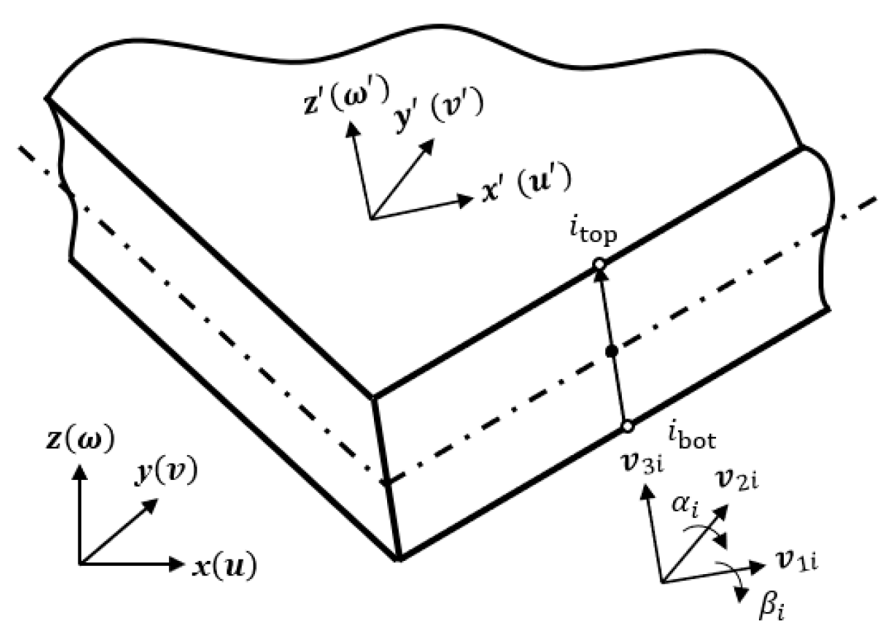
After is determined, the equivalent properties of the armor layer unit cell can be calculated by using Equations (14), (18), and (20). For the macroscale analysis, a four-node solid degenerated shell element based on the Reissner–Mindlin assumption is employed to estimate the response of a flexible riser, where the above-obtained is used, i.e.,
where represent the in-plane displacement; is the out-of-plane bending deflection; is a full biquadratic Lagrange shape function; is the generalized displacement, i.e., , where are the displacements in local directions x, y, and z; and represent the normal rotation (cf. Figure 7). Finally, the element stiffness matrix in the global coordinate system is given by:
where are the isoparametric coordinates of the shell element; is the strain–displacement matrix and can be calculated by using Equation (28); is the transformation matrix from local to global coordinates; and is the determinant of the Jacobi matrix.

Figure 7.
Geometry and coordinate systems for a four-node degenerated shell element.
5. Numerical Examples and Discussion
5.1. Homogenization Analysis of the Armor Layer Unit Cell
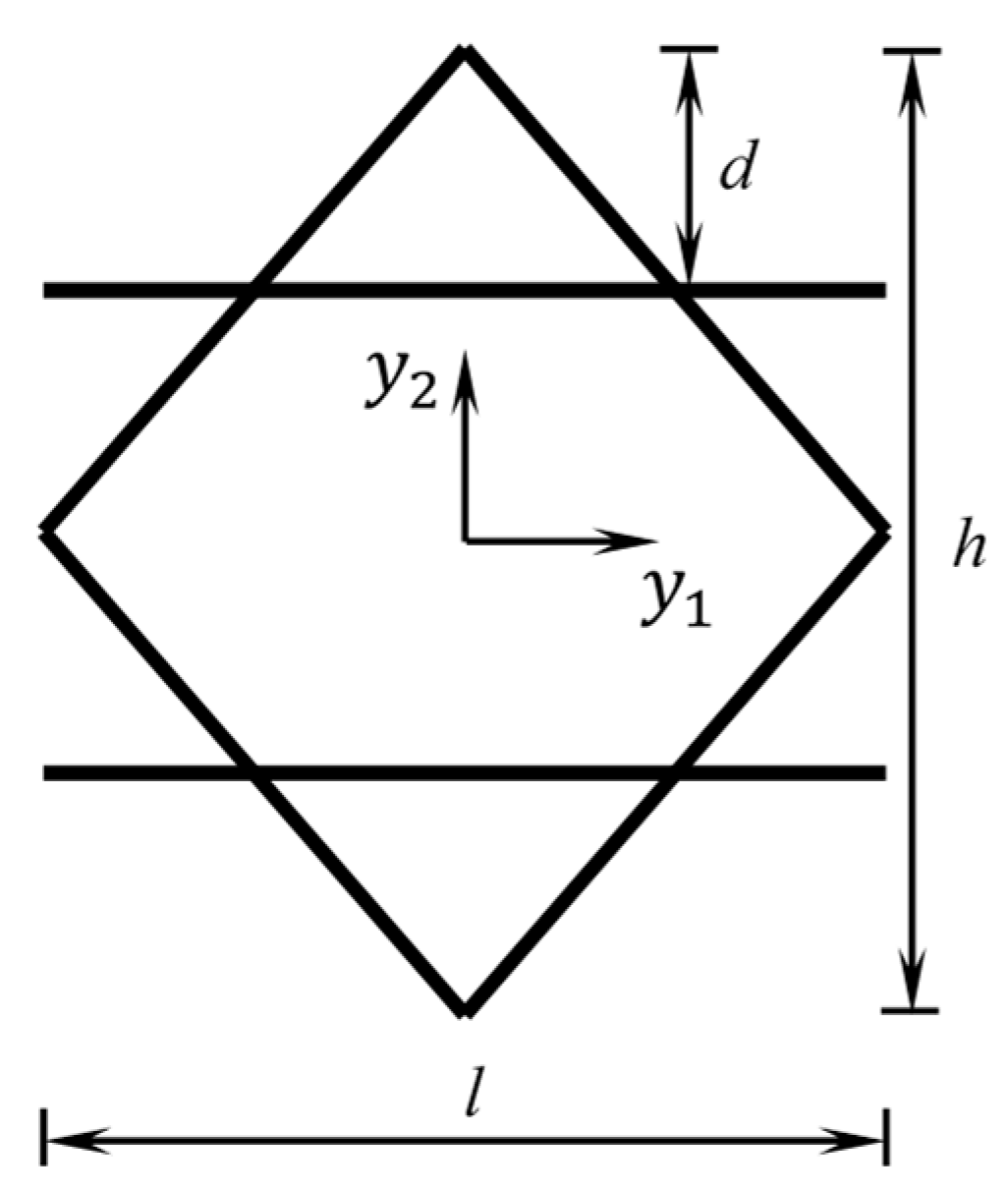
In the present study, a Kagome unit cell, shown in Figure 8, is used to estimate the equivalent properties of the armor layer. In the unit-cell configuration, the inclined beams are used to simulate the steel wires within the armor layer, and the horizontal beams are used to estimate the interactions between the steel wires, as well as between the two armor layers. The equivalent elastic properties of the Kagome unit cell have been previously studied with several methods, including the AH method. However, those works only predicted the in-plane elastic constants of a Kagome unit cell and did not include the elastic constants in the equivalent elastic matrix representing out-of-plane stiffness, such as and . To study the response of a cylindrical shell structure under bending, twisting, and other complex loads, we calculated all the in-plane and out-of-plane elastic constants of the Kagome unit cell by using the NIAH method presented here, providing more comprehensive parameters for the simulation of cylindrical shell structures under complex conditions.

Figure 8.
The configuration of an armor layer unit cell, where the inclined beams are used to simulate the steel wires in the armor layer and the horizontal beams are used to estimate the interactions between the steel wires, as well as between the two armor layers.
The geometrical parameters of the selected armor layer unit cell are shown in Figure 8. This unit cell is used to build the cylindrical shell of a flexible riser, as shown in Figure 9. The radius of the flexible riser is R = 100.0 cm, and its axial length is 1000 cm. The hoop span of the unit cell along the circumferential direction is 5°, which indicates that there are 72 unit cells around the circumference of the flexible riser; thus, the length of the unit cell is 8.73 cm, the height of the unit cell is 10.00 cm, and 100 unit cells are distributed along the axis direction. The distance from the upper horizontal wall to the top of the unit cell is 2.50 cm. A square cross-section with a length of 1.00 is used for each beam within the Kagome unit cell. The unit cell is symmetric about and . An isotropic material model is used for the unit-cell analysis based on AH, and Young’s modulus and Poisson’s ratio are set to 10.00 GPa and 0.3, respectively.
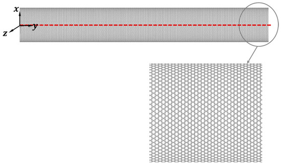
Figure 9.
The FE model of a flexible riser structure composed of micro-unit cells.
The Kagome unit-cell model shown in Figure 8 is established in ANSYS 18.0 software using Beam 188 elements with a mesh size of 2.2 cm. For the equivalent model of the armor layer in macro-analysis, to facilitate the comparison of the analysis results with a FE model, shell 181 elements are used to discretize the macro-model, and the number of elements along the axis and circumference are identical to the number of unit cells. The homogenized equivalent elastic matrix calculated with the NIAH method is
In the work [36], a theoretic formula to calculate the equivalent compliance matrix of a 2D Kagome unit cell is presented, i.e.,
where , , , , and . The elastic constants calculated with Equation (30) and the NIAH method are shown in Table 1. As can be seen, the results calculated by using the method established in this study are in good agreement with the analytical solution in [36]. The main reason for the error might be that the frame structure of a low-density unit cell is approximated as a truss structure in [36]. This approximation decreases the equivalent stiffness of unit cells and increases the error when the material density of the unit cell is relatively higher.

Table 1.
Comparison of parts of equivalent elastic constants of Kagome armor layer unit cell with results in [36].
5.2. Structural Analysis of Armor Layer of Flexible Riser Under Different Loads
To demonstrate the accuracy of the proposed method, a comparison between the analysis results obtained with the NIAH method and a FE model for a flexible riser (cf. Figure 9) is performed below. Additionally, to fully validate the accuracy of the proposed NIAH method, the commonly encountered loading conditions of flexible risers, i.e., tension, three-point bending, and torsion, are considered. In the NIAH analysis, the elastic properties obtained according to Section 5.1 are employed to calculate the displacement response. In the cylindrical shell and FE models, all nodes located in front of the Y-Z plane are selected as representative points (see the red dotted line in Figure 9). The maximum total displacements of the representative nodes are selected to compare the analysis results between the FE and NIAH models, whose relative error is selected as the metric of the approximation degree of the algorithms in this study.
Three kinds of loading and boundary conditions are implemented:
(1) Tension loading conditions: The flexible riser structure has one end fixed, i.e., the left end in Figure 9, and an axial tensile load of 18,000 is distributed uniformly around the circle section on the right end. The displacement comparison of the reference nodes is shown in Figure 10.
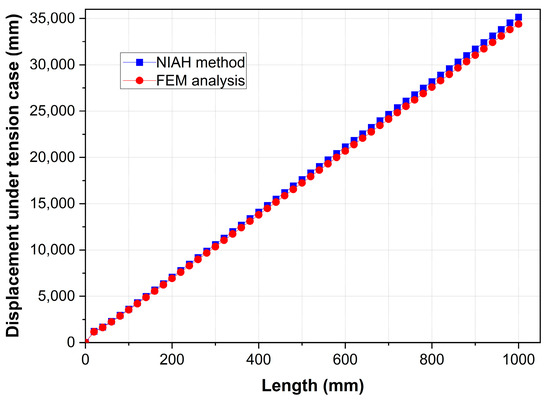
Figure 10.
Comparison of representative node displacements between FE and NIAH models under tension loading case.
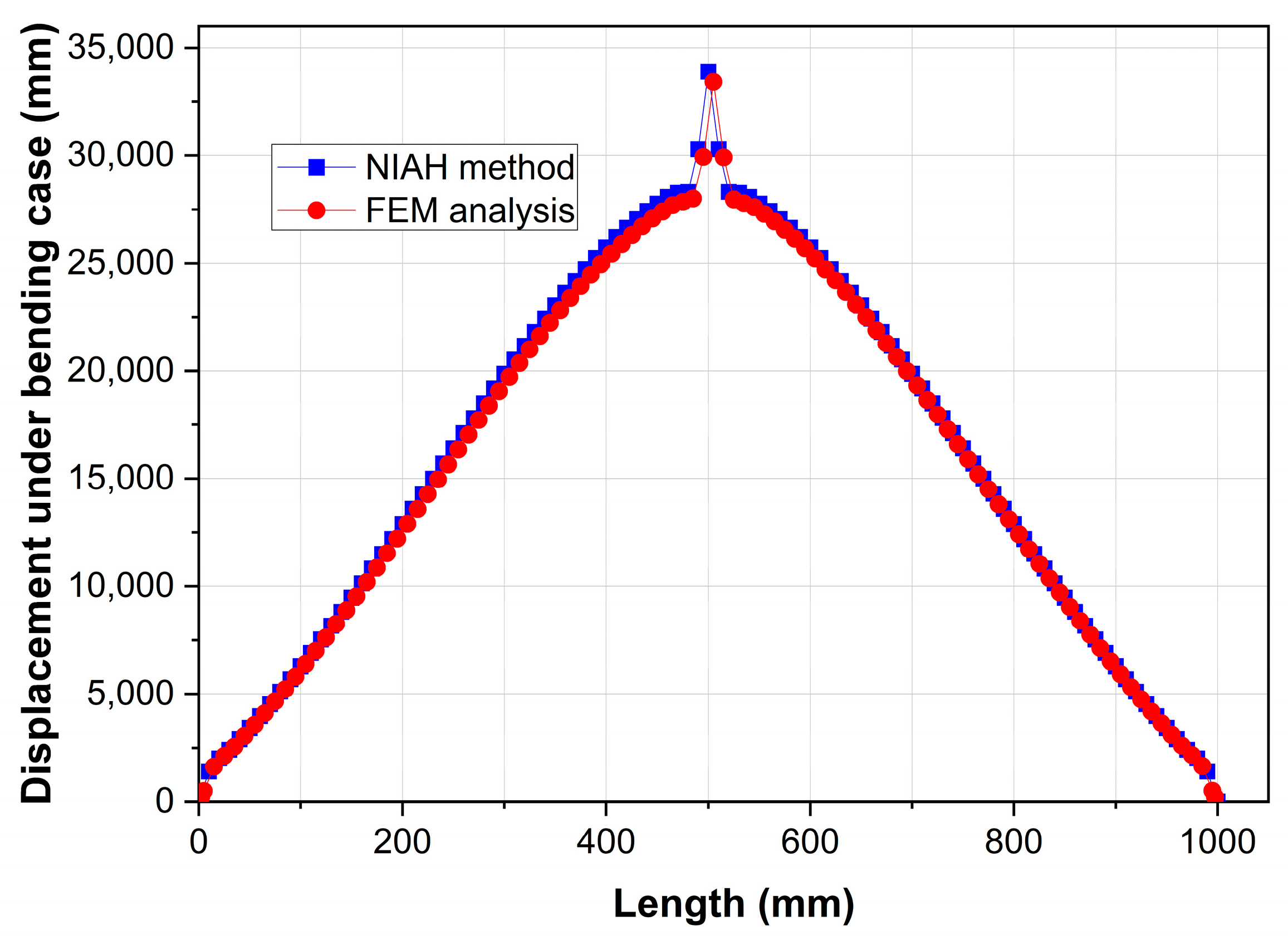
(2) Bending conditions: The flexible structure has the two ends fixed, and transverse loads with a total amplitude of 10,000 are uniformly applied at its middle cross-section. The displacement comparison of the represented nodes is shown in Figure 11.

Figure 11.
Comparison of representative node displacements between FE and NIAH models under bending loading case.
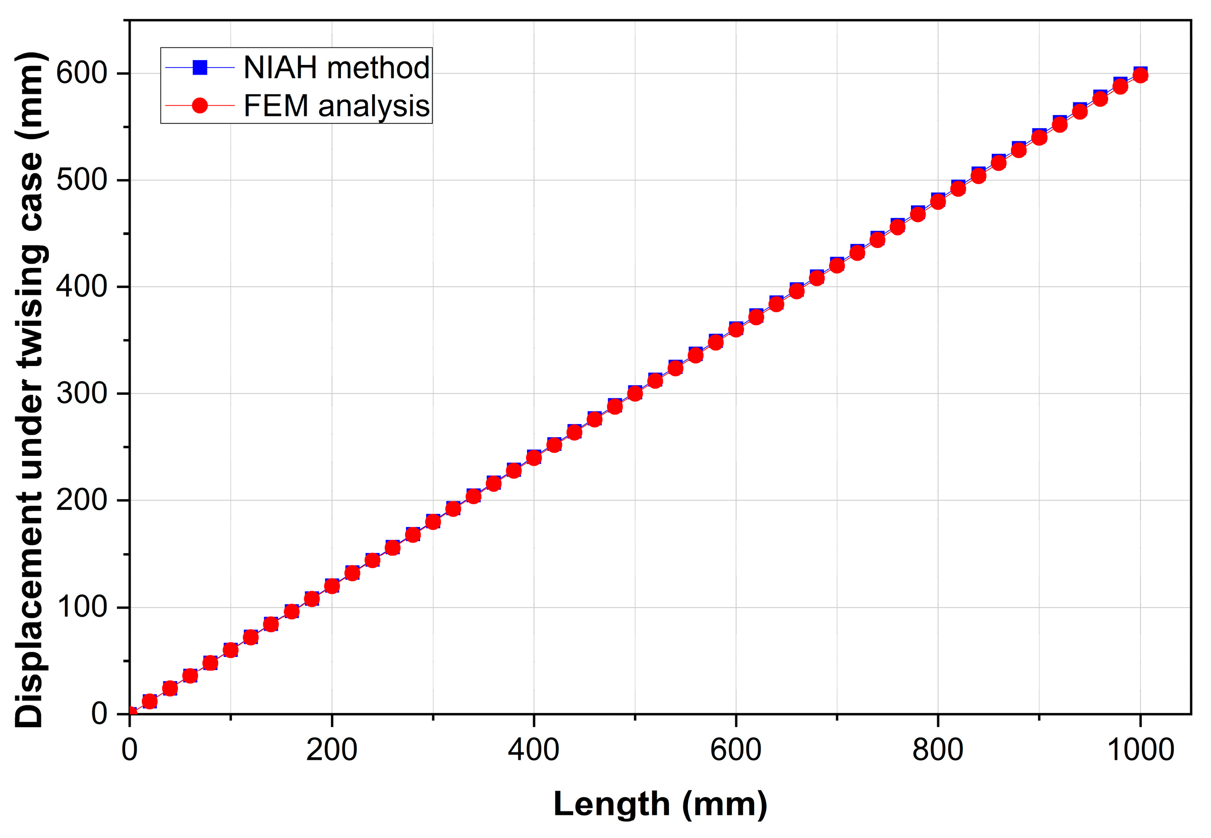
(3) Twisting conditions: The flexible riser structure has one end fixed (left end in Figure 9), and a torque load of 18,000 is applied uniformly around the circle cross-section on the other end. The vector direction of the torque load is the direction pointing away from the fixed end. The displacement comparison of the reference nodes is shown in Figure 12.
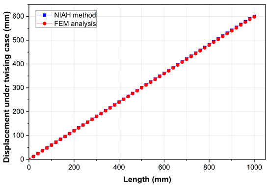
Figure 12.
Comparison of representative node displacements between FE and NIAH models under twisting loading case.
The comparison of the maximum nodal displacements between the accurate finite element model and the equivalent homogenization analysis model under the three loading conditions above is shown in Table 2. As can be seen, the calculation errors of the NIAH method under three kinds of loads are all relatively small, with the largest of which, reaching 2.17%, occurring under tension loading. In this case, the maximum displacement value of the homogenization model is bigger than that of the finite element model. Thus, these structures meet engineering design standards, and the results are conducive to safe operation. The errors are partly due to the fact that the hoop and axial unit cells are all of a finite size, which does not completely satisfy the hypothesis of the AH method that unit cells should be infinitely periodic. This size effect is discussed in detail in the next section.
Table 2.
A comparison between the maximum nodal displacements of the FE and NIAH models under three loading conditions.
Moreover, since the concentrated forces are applied at the middle section of the cylindrical shell to simulate bending deformation, a stress concentration effect is observed. Therefore, a sudden displacement change is observed in Figure 11.
5.3. Size Effect of ARMOR Layer Unit Cells in Flexible Risers
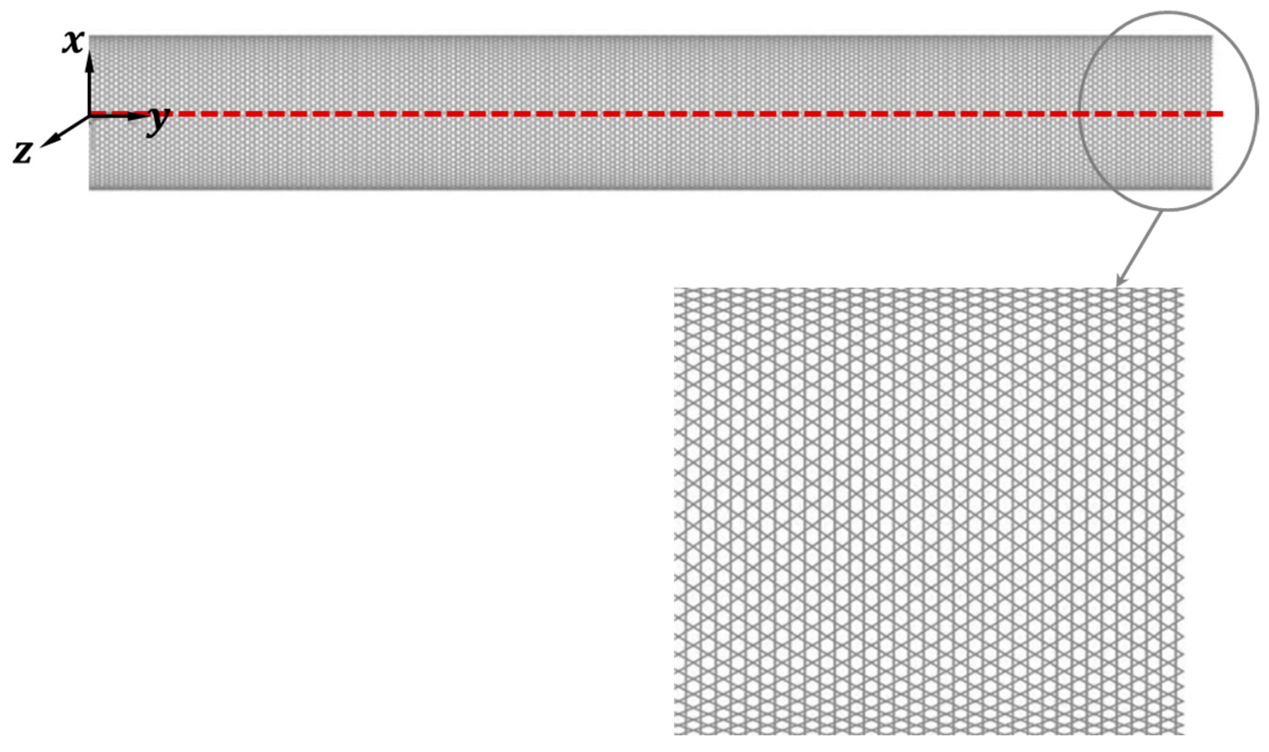
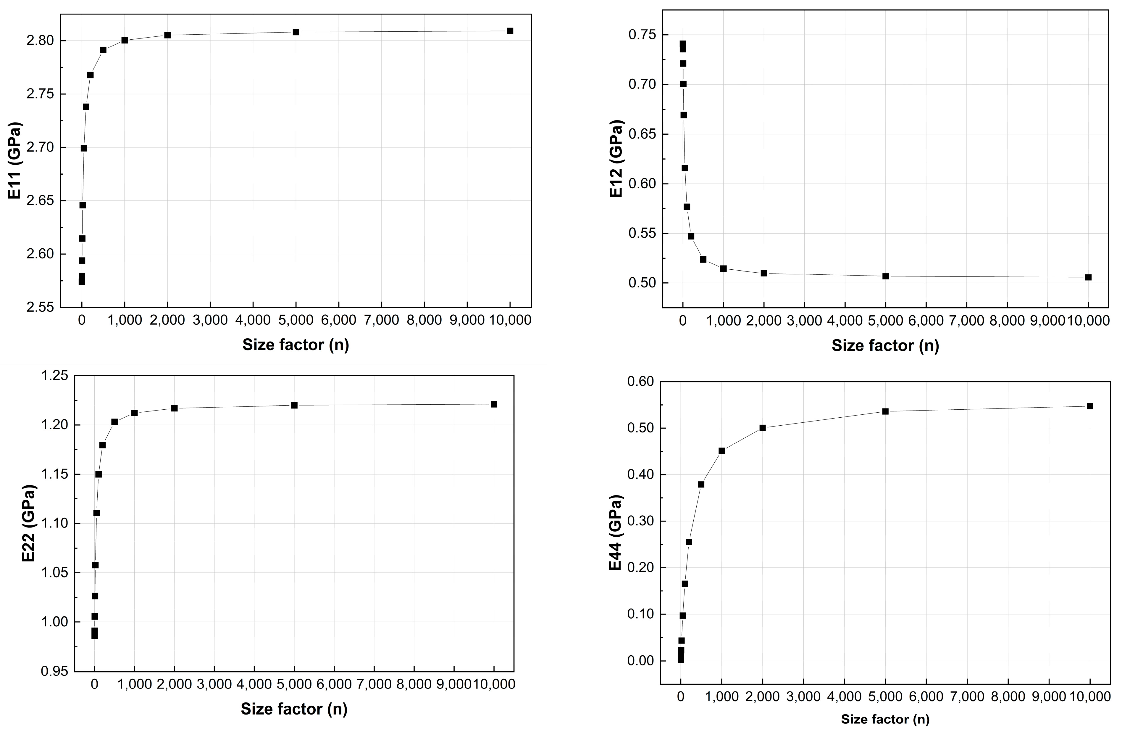
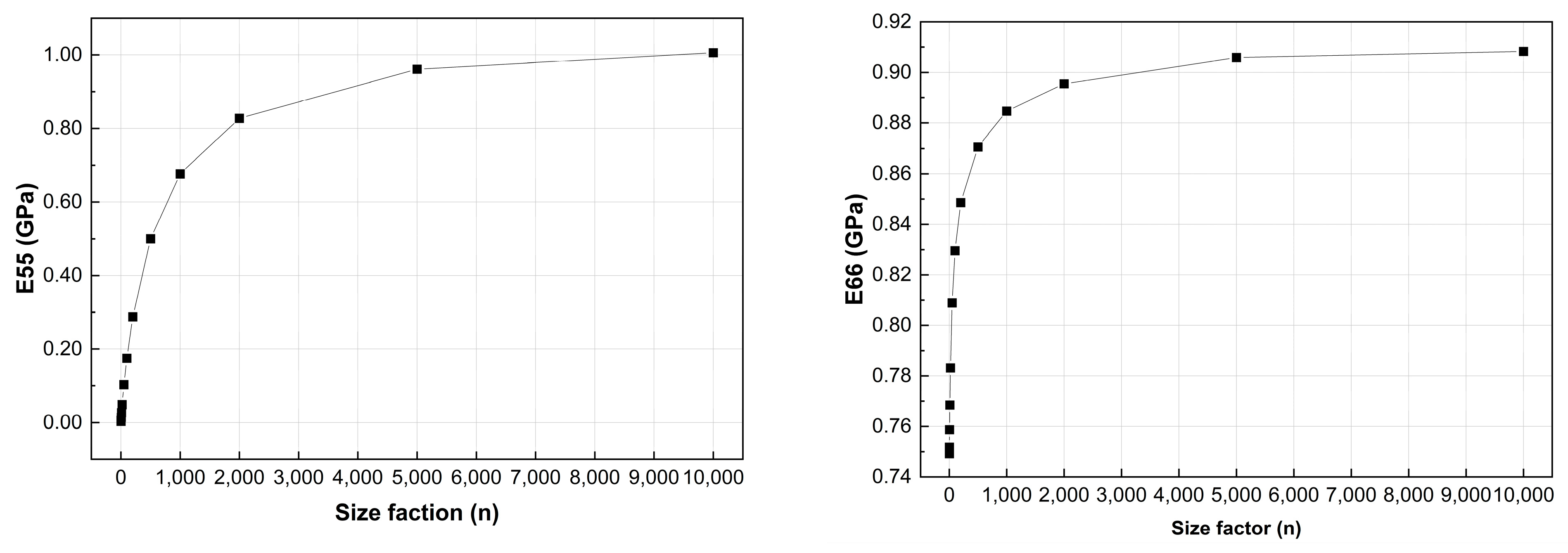
In homogenization theory, an infinitely small unit-cell size is assumed, and a periodic boundary condition is used to approximately simulate the deformation state of the flexible riser. Therefore, the size of the unit cell should be infinitesimal compared with the structure’s characteristic size. For the armor layer of a flexible riser composed of unit cells of finite sizes, an estimation error may occur in the NIAH method. Moreover, the approximation accuracy generally depends on the ratio of the characteristic sizes of the unit cell and macro-structure. In general, a smaller unit-cell size enables a higher approximation accuracy. Therefore, in this section, the geometry size of the armor layer unit cell in the finite element model is varied to study the approximation accuracy of the NIAH method; this provides a reference for the applicability of the method in predicting equivalent properties of flexible riser structures in practical engineering.
The dashed box with a fixed size in Figure 13 can be filled with different numbers of similar armor layer unit cells. When the size factor 1, the representative region denoted by the dashed box only has one unit cell; when 2, it contains two unit cells each in the horizontal and vertical directions of the representative region. Therefore, when , the representative region contains unit cells. In size effect analysis, the material volume fractions for different size factors are identical, which indicates that a larger size factor n leads to thinner walls of the unit cell.
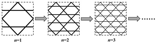
Figure 13.
Illustration of size effect of armor layer unit cells.
When the size factor n = 1, the height of unit cell is = 52.35, the length is = 60.00, the distance from the upper horizontal wall to the top of the unit cell is = 15.00, and the square section of the walls has a side length of .
For different size factors, the equivalent elastic properties of the unit cell are calculated by using the proposed NIAH method. The calculated equivalent elastic properties of unit cells with different size factors are listed in Table 3.
Table 3.
Variation in elastic properties of armor layer unit cells with different size factors .
From Table 3, it can be found that the equivalent elastic constants of unit cells have an evident size effect, i.e., they change with the size factor n even for unit cells with the same material volume fraction. In Yan et al. [23], the size effect of the truss-based unit cell was studied. They found that the equivalent elastic properties of truss unit cells did not vary when the same material volume was employed, i.e., no size effect was observed. On the other hand, here, we find that the unit cell modeled with a frame composed of beam elements shows a significant size effect. This can be explained as follows: The stiffness of the rods in a truss structure is proportional to , where denotes the cross-sectional area of the rod and denotes the length of the component of a rod. If the size of the truss unit cell (the length of the rod) is reduced to 1/n of the original, the original unit cell is decomposed into small unit cells, which makes the total length of all of the rods times the original one. To ensure the same material volume, the cross-sectional area of the rods should be of the original truss; thus, the of each rod does not change. Therefore, there is no size effect on the stiffness of the unit cell. However, for the frame model of armor layer unit cells, the stiffness of the rods is in relation with , , , and , where denotes the bending moment of inertia of the beam components. If the size of the frame unit cell is reduced to of the original, the two stiffness coefficients and change even when the sectional shape is not varied. Therefore, the stiffness of the unit cells changes with the size factor , thereby showing a size effect. For the practical analysis of a flexible riser, if its deformation is dominantly in plane, a truss element can be used for the equivalent analysis of the unit cell. Otherwise, a beam element is required when the out-of-plane deformation is significant.
According to the data in Table 3, in addition to the non-diagonal elements decreasing, the rest of the diagonal elements increase with an increase in the size factor . To clearly show the trend in each equivalent elastic constant with the change in size factor , the plots in Figure 14 were drawn based on sets of data. As the size factor increases, each equivalent elastic constant tends to converge to the elastic constant of the orthotropic homogeneous material.
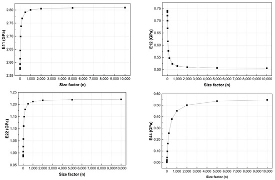
Figure 14.
Variation in elastic properties of armor layer unit cell with different size factors .
From the above analysis, the size factor has a significant effect on the precision of the equivalent properties. Moreover, the size effect decreases as the size factor increases, which indicates that an accurate estimation of the unit cell can be obtained when a large number of unit cells are contained within the flexible riser. In practical applications, the size of the unit cell is much smaller than the length of the flexible riser, which means that the NIAH method can provide a good estimation of the structural performance of flexible risers. However, if a small number of unit cells are contained within a flexible riser, the FE model should be adopted for structural analysis, which may not incur a significant computational cost.
6. Concluding Remarks
In the present study, a novel implementation of the asymptotic homogenization method is established to determine the properties of flexible riser structures that overcome the computational cost caused by the significant difference between the sizes of the flexible riser and steel wires. In the proposed method, the beam model is used to construct a micro-unit cell, and an equivalented cylindrical shell model is used to estimate the displacement response of the flexible riser’s armor layer. Due to easy co-implementation with the abundant element libraries of commercial FE analysis software such as ANSYS, this method can analyze the equivalent elastic properties of various forms of unit cells, which simplifies the calculation process and extends the application range. This eliminates the complicated formula derivations and programming workload inherent in the original AH method, thereby reducing the computational complexity of calculating the equivalent properties of unit cells and improving the computational efficiency.
By using the proposed NIAH method, the equivalent elastic properties of the armor layer unit cell and the displacement responses of the flexible riser armor layer under different loading conditions are obtained. Then, a comparison between the numerical results of the finite element model and the NIAH model is performed. It is found that the NIAH method can provide a good estimation of the displacement response of the armor layer in flexible risers when the size of the periodic unit cell is much smaller than the characteristic structural size. The following conclusions can be obtained according to the results of the numerical experiments:
(1) The unit cell of the armor layer in flexible risers can be simplified to a 2D unit cell when the curvature effects are not taken into account. However, to perform shell structure analysis on the equivalent macro-model, the out-of-plane-related shear modulus of the unit cell needs to be calculated in order to consider the ability to resist corresponding shear loads and can be well estimated with the proposed NIAH method.
(2) The elastic constant of a thin-walled cylindrical shell has a smaller effect on structural performance according to the thin-plate theory. So, the third diagonal element in the 6 × 6 equivalent elastic matrix inputted in commercial FE software obtained with the NIAH method can be assigned a non-zero value to ensure that the stiffness matrix, whose value has no effects on the calculation results, is positively defined.
(3) Different from the truss unit cell, the frame unit cell displays size effects for the same material volume fraction, i.e., the equivalent elastic constants of unit cells change with the variation in the characteristic size of the unit cell. As the size factor of the unit cell increases, the equivalent elastic constants tend to approach the constant elastic properties.
Although a Reissner–Mindlin shell is used for flexible risers on the macroscale, which allows us to consider the shear effect caused by bending and twisting deformations, nonlinear factors (such as plastic deformation and contact between steel wires) are neglected. A more comprehensive study will be performed in the future to adapt our method to complex applications, particularly in deep-water environments. Simultaneously, the proposed analysis method can also be extended to consider dynamic loads and nonlinear material properties. Moreover, a method to optimize configurations based on the NIAH method can also be studied; e.g., a ground structure method can be employed to optimize the radius of each beam and find a new configuration of unit cells that improves the performance of flexible risers.
Author Contributions
Conceptualization, M.L. and J.Y.; methodology, H.L. and J.Y.; software, E.L.; validation, M.L. and F.L.; formal analysis, F.L. and H.L.; investigation, M.L.; data curation, E.L.; writing—original draft preparation, M.L. and F.L; writing—review and editing, H.L.; visualization, J.Y. and H.L. All authors have read and agreed to the published version of the manuscript.
Funding
This research was funded by the Natural Science Foundation of Liaoning Province of China (2023-BSBA-052).
Institutional Review Board Statement
Not applicable.
Informed Consent Statement
Not applicable.
Data Availability Statement
Dataset available on request from the authors.
Conflicts of Interest
Miaoer Liu, Endao Li and Fangqiu Li were employed by CNOOC Gas & Power Group Co., Ltd. The remaining authors declare that the research was conducted in the absence of any commercial or financial relationships that could be construed as a potential conflict of interest.
References
- Amaechi, C.V.; Reda, A.; Ja’e, I.A.; Wang, C.; An, C. Guidelines on Composite Flexible Risers: Monitoring Techniques and Design Approaches. Energies 2022, 15, 4982. [Google Scholar] [CrossRef]
- Korotygin, D.; Nammi, S.K.; Pancholi, K. The Effect of Ice Floe on the Strength, Stability, and Fatigue of Hybrid Flexible Risers in the Arctic Sea. J. Compos. Sci. 2023, 7, 212. [Google Scholar] [CrossRef]
- Zhang, X.; Huang, W.; Ma, W.; Su, L.; Tian, H.; Yang, Y. Cross-Sectional Mechanical Characteristics and Sensitivity Analysis of Unbonded Flexible Risers under Axial Loads. J. Ocean. Eng. Sci. 2023, 17, 23. [Google Scholar]
- Liu, Q.; Qu, Z.; Chen, F.; Liu, X.; Wang, G. Review of the Development of an Unbonded Flexible Riser: New Material, Types of Layers, and Cross-Sectional Mechanical Properties. Materials 2024, 17, 2560. [Google Scholar] [CrossRef]
- Duan, J.; Wang, X.; Zhou, J.; You, Y. Effect of Internal Solitary Wave on the Dynamic Response of a Flexible Riser. Phys. Fluids 2023, 35, 017107. [Google Scholar]
- Gasparetto, V.; Hernalsteens, T.; Britto, J.F.F.H.; Leao, J.F.A.; Dos Santos, T.D.F.; De Oliveira, R.C. Optimization Applied to Buzios Flexible Riser Systems and Subsea Layout. In Proceedings of the Offshore Technology Conference 2021, Houston, TX, USA, 16–19 August 2021. [Google Scholar]
- Bahtui, A.; Bahai, H.; Alfano, G. A Finite Element Analysis for Unbonded Flexible Risers under Torsion. J. Offshore Mech. Arct. Eng. 2008, 130, 041301. [Google Scholar] [CrossRef]
- Liu, Q.; Xue, H.; Tang, W.; Yuan, Y. Theoretical and Numerical Methods to Predict the Behaviour of Unbonded Flexible Riser with Composite Armour Layers Subjected to Axial Tension. Ocean. Eng. 2020, 199, 107038. [Google Scholar]
- Knapp, R.H. Derivation of a New Stiffness Matrix for Helically Armoured Cables Considering Tension and Torsion. Int. J. Numer. Methods Eng. 1979, 14, 515–529. [Google Scholar]
- Xiang, L.; Wang, H.; Chen, Y.; Guan, Y.; Wang, Y.; Dai, L. Modeling of Multi-Strand Wire Ropes Subjected to Axial Tension and Torsion Loads. Int. J. Solids Struct. 2015, 58, 233–246. [Google Scholar]
- Sævik, S.; Thorsen, M.J. An Analytical Treatment of Buckling and Instability of Tensile Armors in Flexible Pipes. J. Offshore Mech. Arct. Eng. 2017, 139, 041701. [Google Scholar]
- Anastasiadis, P.S.; Theotokoglou, E.E.; Michailides, C. Numerical Analysis of Stress Concentration Factors on Tensile Armour Wires inside the End-Fitting of an Axially Tensed Unbonded Flexible Pipe. J. Struct. Integr. Maint. 2020, 5, 72–86. [Google Scholar]
- Zhang, M.; Chen, X.; Fu, S.; Guo, Y.; Ma, L. Theoretical and Numerical Analysis of Bending Behavior of Unbonded Flexible Risers. Mar. Struct. 2015, 44, 311–325. [Google Scholar]
- Ren, S.-F.; Xue, H.-X.; Tang, W.-Y. Analytical and Numerical Models to Predict the Behavior of Unbonded Flexible Risers under Torsion. China Ocean Eng. 2016, 30, 243–256. [Google Scholar]
- Gautam, M.; Katnam, K.B.; Potluri, P.; Jha, V.; Latto, J.; Dodds, N. Hybrid Composite Tensile Armour Wires in Flexible Risers: A Multi-Scale Model. Compos. Struct. 2017, 162, 13–27. [Google Scholar]
- Penta, R.; Gerisch, A. An introduction to asymptotic homogenization. In Multiscale Models in Mechano and Tumor Biology: Modeling, Homogenization, and Applications; Springer International Publishing: Berlin/Heidelberg, Germany, 2017; pp. 1–26. [Google Scholar]
- Kalamkarov, A.L.; Georgiades, A.V. Asymptotic Homogenization Models for Smart Composite Plates with Rapidly Varying Thickness: Part I-Theory. Int. J. Multiscale Comput. Eng. 2004, 2, 133–148. [Google Scholar]
- Pecullan, S.; Gibiansky, L.; Torquato, S. Scale Effects on the Elastic Behavior of Periodic Andhierarchical Two-Dimensional Composites. J. Mech. Phys. Solids 1999, 47, 1509–1542. [Google Scholar]
- Efendiev, Y.; Hou, T. Multiscale Finite Element Methods for Porous Media Flows and Their Applications. Appl. Numer. Math. 2007, 57, 577–596. [Google Scholar]
- Zhang, H.-W.; Wu, J.-K.; Lü, J.; Fu, Z.-D. Extended Multiscale Finite Element Method for Mechanical Analysis of Heterogeneous Materials. Acta Mech. Sin. 2010, 26, 899–920. [Google Scholar]
- Hassani, B.; Hinton, E. A Review of Homogenization and Topology Optimization I—Homogenization Theory for Media with Periodic Structure. Comput. Struct. 1998, 69, 707–717. [Google Scholar]
- Cai, Y.; Xu, L.; Cheng, G. Novel Numerical Implementation of Asymptotic Homogenization Method for Periodic Plate Structures. Int. J. Solids Struct. 2014, 51, 284–292. [Google Scholar]
- Yan, J.; Cheng, G.; Liu, S.; Liu, L. Comparison of Prediction on Effective Elastic Property and Shape Optimization of Truss Material with Periodic Microstructure. Int. J. Mech. Sci. 2006, 48, 400–413. [Google Scholar]
- Yan, J.; Cheng, G. Multiscale Optimization and Materials Design; World Scientific: Singapore, 2020; Volume 3. [Google Scholar]
- Li, Q.; Chen, W.; Liu, S.; Wang, J. A Novel Implementation of Asymptotic Homogenization for Viscoelastic Composites with Periodic Microstructures. Compos. Struct. 2019, 208, 276–286. [Google Scholar] [CrossRef]
- Zhao, J.; Li, H.; Cheng, G.; Cai, Y. On Predicting the Effective Elastic Properties of Polymer Nanocomposites by Novel Numerical Implementation of Asymptotic Homogenization Method. Compos. Struct. 2016, 135, 297–305. [Google Scholar] [CrossRef]
- Cheng, G.-D.; Cai, Y.-W.; Xu, L. Novel Implementation of Homogenization Method to Predict Effective Properties of Periodic Materials. Acta Mech. Sin. 2013, 29, 550–556. [Google Scholar] [CrossRef]
- Sigmund, O. Materials with Prescribed Constitutive Parameters: An Inverse Homogenization Problem. Int. J. Solids Struct. 1994, 31, 2313–2329. [Google Scholar] [CrossRef]
- Xu, L.; Cheng, G. Shear Stiffness Prediction of Reissner–Mindlin Plates with Periodic Microstructures. Mech. Adv. Mater. Struct. 2017, 24, 271–286. [Google Scholar]
- Fan, Z.; Yan, J.; Wallin, M.; Ristinmaa, M.; Niu, B.; Zhao, G. Multiscale Eigenfrequency Optimization of Multimaterial Lattice Structures Based on the Asymptotic Homogenization Method. Struct. Multidiscip. Optim. 2010, 61, 983–998. [Google Scholar] [CrossRef]
- Zhang, Y.; Shang, S.; Liu, S. A Novel Implementation Algorithm of Asymptotic Homogenization for Predicting the Effective Coefficient of Thermal Expansion of Periodic Composite Materials. Acta Mech. Sin. 2017, 33, 368–381. [Google Scholar] [CrossRef]
- Chen, D.; Liu, L.; Chu, L.; Liu, Q. Analytical Solution of Thermo–Mechanical Properties of Functionally Graded Materials by Asymptotic Homogenization Method. Materials 2022, 15, 3073. [Google Scholar] [CrossRef]
- Dong, Z.; Quan, W.; Ma, X.; Li, X.; Zhou, J. Asymptotic Homogenization of Effective Thermal-Elastic Properties of Concrete Considering Its Three-Dimensional Mesostructure. Comput. Struct. 2023, 279, 106970. [Google Scholar] [CrossRef]
- Wang, B.; Tian, K.; Hao, P.; Zheng, Y.; Ma, Y.; Wang, J. Numerical-Based Smeared Stiffener Method for Global Buckling Analysis of Grid-Stiffened Composite Cylindrical Shells. Compos. Struct. 2016, 152, 807–815. [Google Scholar]
- Tian, W.; Qi, L.; Chao, X.; Liang, J.; Fu, M. Periodic Boundary Condition and Its Numerical Implementation Algorithm for the Evaluation of Effective Mechanical Properties of the Composites with Complicated Micro-Structures. Compos. Part B Eng. 2019, 162, 1–10. [Google Scholar]
- Niu, B.; Wang, B.; Xu, S. Effective Mechanical Properties of Orthotropic Kagome Honeycomb Materials. Chin. J. Solid Mech. 2009, 30, 600–608. [Google Scholar]


Disclaimer/Publisher’s Note: The statements, opinions and data contained in all publications are solely those of the individual author(s) and contributor(s) and not of MDPI and/or the editor(s). MDPI and/or the editor(s) disclaim responsibility for any injury to people or property resulting from any ideas, methods, instructions or products referred to in the content. |
© 2025 by the authors. Licensee MDPI, Basel, Switzerland. This article is an open access article distributed under the terms and conditions of the Creative Commons Attribution (CC BY) license (https://creativecommons.org/licenses/by/4.0/).