Article

Assessment of Undrained Bearing Capacity of Foundations on Anisotropic Clay Slope Under Inclined Load

1
School of Ocean Engineering, Harbin Institute of Technology, Weihai 264209, China
2
Chifeng Construction Engineering Quality and Safety Technical Service Center, Chifeng 024009, China
3
School of Civil Engineering, Tianjin University, Tianjin 300072, China
*
Author to whom correspondence should be addressed.
J. Mar. Sci. Eng. 2025, 13(4), 681; https://doi.org/10.3390/jmse13040681
Submission received: 6 March 2025 / Revised: 19 March 2025 / Accepted: 24 March 2025 / Published: 27 March 2025
(This article belongs to the Section Ocean Engineering)

Abstract

:
The development of marine energy requires reliable foundations, which may be located near submarine slopes. This paper utilizes the lower bound limit analysis (LBLA) to analyze the undrained bearing capacity of foundations on slopes with anisotropy and linearly increasing strength with depth. The anisotropic undrained strength (AUS) model is employed to simulate the anisotropy of the slope soil. This study considers five variables that affect the bearing capacity: the normalized foundation setback (L/B), load angle (θ), strength ratio (suc/γB), heterogeneous index (ρB/suc), and anisotropy ratio (re). Here, suc represents the soil strength obtained from triaxial compression tests, while ρ denotes the strength gradient. The results indicate that the bearing capacity increases with the increase in L/B, suc/γB, ρB/suc, and re, while the maximum bearing capacity corresponds to a load angle ranging from 75° to 90°. The failure modes of foundations under different boundary conditions were presented and discussed. To establish the relationship between the foundation bearing capacity and each variable, the multivariate adaptive regression splines (MARS) is introduced. The MARS results indicate that θ is the most significant variable, while the relative importance of L/B is the lowest; neither can be neglected in practical engineering. The empirical equation based on the MARS algorithm can accurately predict the bearing capacity of foundations in non-homogeneous and anisotropic clay. These results offer critical guidance for engineering practice, enabling efficient design of marine foundations near slopes while accounting for soil anisotropy and heterogeneous strength gradients, thereby reducing risks of instability in offshore energy infrastructure.

1. Introduction

The sea floor refers to the crustal surface composed of oceanic plates, which closely resembles the terrestrial landscapes with features such as mountains, deep valleys, gentle slopes, and plains. As the exploitation of marine energy resources (e.g., oil, natural gas, and wind energy) advances, the placement of foundations in proximity to slopes becomes a common scenario in ocean engineering. The bearing capacity of foundations on slopes is a significant research topic, which has been extensively studied by numerous scholars using various methods. Georgiadis (2010) [1] pioneered the application of the upper-bound limit analysis to quantify undrained foundation capacity near slope edges. Based on the same methodology, Yang et al. (2021) [2] extended the analytical framework to incorporate seismic excitation effects, establishing critical load capacity factors under dynamic loading conditions. Lee and Manjunath (2000) [3], Castelli et al. (2012) [4], and Salih Keskin and Laman (2013) [5] explored the failure mechanism of shallow foundations on slopes through model tests and assessed the effect of parameters such as setback distance from the slope crest, slope angle, and footing width on the ultimate bearing capacity. Naeini et al. (2012) [6], Javdanian (2017) [7], and Satvati et al. (2020) [8] employed numerical analysis to quantify enhancement in bearing capacity and the reduction in the settlement of foundations on slopes achieved by using geosynthetic materials.
In early studies, slope soils were often simplified to homogeneous soils [9,10,11]. As research progressed, heterogeneous soil masses, where soil undrained strength increases linearly with depth, were incorporated into the scope of investigation [12,13,14]. The normally consolidated or over-consolidated clays are prevalent in the seabed and their undrained strength also increases linearly with depth [15]. Chen et al. (2022) [16] found that for shallow foundations with small embedment ratio, the bearing capacity factor increases with the increase in the homogeneity index. This study takes into account both of these soil properties.
In addition to undrained strength heterogeneity, natural clays often exhibit anisotropy due to the soil mineral composition, depositional direction, and pore characteristics [16,17,18]. Many studies have found that the undrained strength of clays obtained from triaxial compression (suc), direct shear (sus), and triaxial extension (sue) tests are not the same. The anisotropy of soil undrained strength can be described by factors including re (=sue/suc) and rs (=sus/suc). Experimental investigations by Ladd (1991) [19] demonstrated an inverse correlation between clay plasticity index and undrained strength anisotropy magnitude. Quantitatively, the normalized strength ratios (re = 0.5–0.8; rs = 0.7–0.85) exhibited systematic reduction with increasing soil plasticity, highlighting stress path dependency in anisotropic clay behavior. Won (2013) [20] summarized 203 sets of triaxial test data from Europe, Asia, and North America, and found that when anisotropic data were grouped by depositional environment, anisotropy did not show a significant correlation with the plasticity index, with re ranging from 0.23 to 1.27. To describe the anisotropic undrained strength of soil, Casagrande and Carillo (1944) [21] suggested expressing it as a function of the angle of orientation (δ) of the major principal stress (σ1). For plane strain problems, the anisotropic failure envelope postulated by Davis and Christian (1971) [22] demonstrates elliptical stress trajectory dependence. This formulation uniquely couples normal stress components (σxx, σzz) with shear stress τzx through principal stress rotation mechanics, effectively capturing strength differential effects in structured clays. For three-dimensional problems, Prevost (1979) [23] proposed an anisotropic undrained strength criterion for anisotropic clays, which involves two material constants, namely sue and suc or suc and re. Recently, Krabbenhøft et al. (2019) [24] extended the generalized Tresca model to anisotropic materials, proposing the anisotropic undrained strength (AUS) model, which is tailored for the undrained conditions of clays. The model’s depiction of unequal compressive and tensile strengths is fundamentally attributed to the Lode angle effect. This model has been extensively utilized by researchers to investigate a range of undrained stability issues [25,26,27], which is also employed in this study to explore the undrained bearing capacity of foundations on the anisotropic clay slope.
In the marine environment, structures are subjected to vertical loads from the superstructure and horizontal loads induced by wind and waves, which creates a certain inclination angle (i.e., θ in Figure 1 may not equal 90°) between the load and the foundation. The undrained bearing capacity of shallow foundations on slopes is influenced by various variables (see Figure 1), such as the height (H) and inclination angle (β) of the slope, strength ratio (suc/γB), heterogeneity (ρB/suc), and anisotropy (re and rs) of soil, foundation location or setback distance from slope (L), and load angle (θ). It is quite a challenge to establish a direct empirical equation that relates these variables to undrained bearing capacity. This paper introduces multivariate adaptive regression splines (MARS), a powerful nonlinear function approximator originally proposed by Friedman (1991) [28]. MARS is a reliable regression method that employs a series of basis functions to describe the relationship between multiple input variables and output values. Compared to conventional machine learning algorithms, MARS possesses good computational efficiency and can more intuitively establish the complex relationship between undrained bearing capacity and various variables through empirical equations. Recently, MARS has garnered widespread attention in geotechnical engineering research [29,30,31].
This research adopts an integrated analytical framework combining lower bound limit analysis (LBLA) [32] with the AUS constitutive model to evaluate the bearing capacity characteristics of shallow foundations on anisotropic clay slopes. The investigation systematically examines multiple influencing factors, namely soil strength anisotropy ratios, material heterogeneity, foundation offset distances relative to slope crests, and load inclination angles, with the analytical outcomes visualized through comprehensive dimensionless design charts. Particular attention is given to the identification and interpretation of characteristic failure mechanisms through representative case studies, elucidating the parametric influences on foundation performance. Furthermore, the numerical outputs derived from LBLA simulations are processed using MARS methodology, establishing robust correlations between boundary condition variables and the resulting undrained bearing capacity. The relative significance of each parameter is quantitatively assessed, while the predictive accuracy of the developed models is rigorously evaluated against multiple statistical performance metrics.

2. Methodology

2.1. Lower Bound Limit Analysis (LBLA)

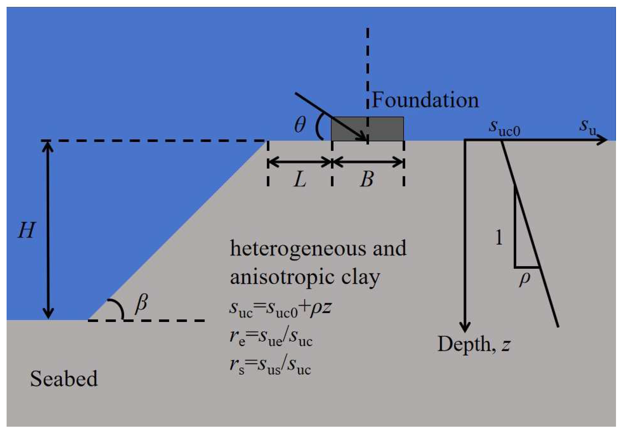
2.1.1. Numerical Model
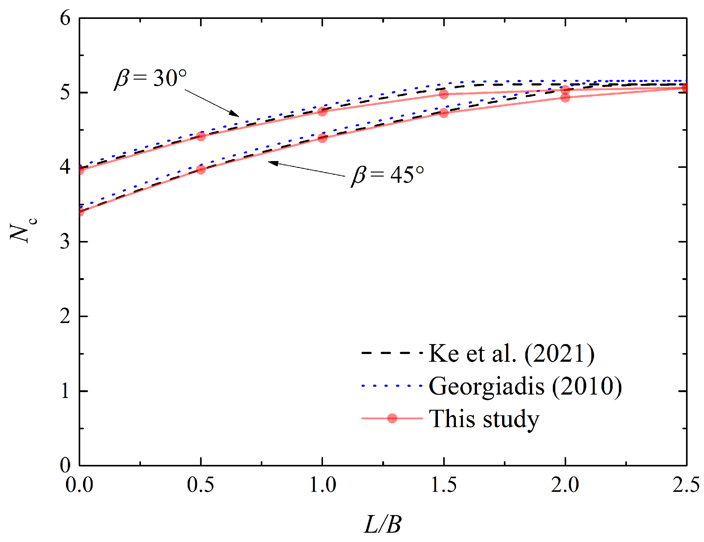
The lower bound limit analysis was conducted using the finite element software OPTUM G2 (2020) [32]. The numerical simulation incorporated a rigid foundation element with characteristic width B = 2 m. Spatial configuration was parametrized through normalized setback distance L/B, where L represents the distance from the foundation to the crest of the slope. A comprehensive parametric study was conducted across six discrete positions: 0, 0.5, 1, 1.5, 2, and 2.5. This dimensionless scheme enables generalized application across geometrically similar slope-foundation systems. The height of the slope H was set at 5 m (i.e., 2.5 times the width of the foundation), with an inclination angle β of 45 degrees. To avoid boundary effects, the considered soil slope has a width of 18 B and a height of 7.5 B. The bottom of the soil was fixed, allowing no displacement to occur, while the sides were restricted against horizontal movement (see the green symbol in Figure 2). The load reference point (LRP) was located at the center of the foundation base, and the load angle θ varies from 0° (away from the slope) to 180° (towards the slope).
The soil material was modeled as AUS clay, with a unit weight of 20 kN/m3. The soil strength derived from triaxial compression is given as suc = suc0 + ρz, where suc0 is the undrained shear strength at the ground level, ρ is the gradient, and z denotes the depth from the ground surface. The heterogeneity of the soil was represented by ρB/suc. In this paper, ρB/suc values of 0, 0.5, and 1 were considered. The anisotropy of the soil is characterized by re and rs. Here, only re was used to represent the anisotropy of the soil, while rs was taken as 2re/(1 + re) following the suggestion of Krabbenhøft et al. (2019) [24]. The values of re considered were 0.6, 0.8, and 1. Additionally, strength ratios suc/γB of 0.5, 1, 1.5, and 2 were considered by varying suc.
Although the foundation base is in full contact with the soil, stress distribution is typically non-uniform, with significant stress concentrations occurring at the corners due to geometric discontinuities. These regions are more prone to deformation and failure, necessitating finer mesh resolution to accurately capture localized stress gradients and failure mechanisms. To capture corner stress concentrations, fan-shaped mesh clusters were parametrically assigned to foundation edge nodes. The discretization scheme specifies an angular split of 15° and a minimum element size of 0.02 B. Before the analysis, the element type was set to Lower, and mesh adaptivity was enabled. The program starts with an initial mesh of 1000 elements and, after three iterations, ultimately generates a mesh of approximately 5000 elements. Figure 2 illustrates the adaptive mesh of the foundation on the crest of an isotropic and homogeneous slope. It can be observed that the mesh is sparse in the boundary regions of the soil and dense near the foundation, thus, the adaptive mesh could effectively capture the failure modes of the soil. Table 1 lists the selected ranges of the dimensionless input parameters, which are based on the study of Georgiadis [10] and Kumar et al. (2023) [33].

2.1.2. Validation

To verify the numerical model, this paper compares the undrained bearing capacity of the foundation Fu obtained from the numerical model in the previous section with the results of previous studies, considering isotropic and homogeneous soil slopes with inclination angles of 30° and 45°. The undrained bearing capacity is typically expressed in a dimensionless form as Nc = Fu/Bsuc, where Nc is also known as the bearing capacity factor.
Figure 3 presents the results for H/B = 2.5, suc/γB = 2.5, and ρB/suc = 0, which are derived from the finite element method [10] and the lower bound limit analysis method [34] and this paper. It can be observed that the results of this paper are essentially consistent with those of previous studies. The results of Georgiadis (2010) [10] are slightly higher than those of this paper, which may be attributed to the lower bound method often providing a conservative result. The results of Ke et al. (2021) [34] closely match those of this paper when l/b is small, with a maximum error of 2.1%. Notably, with increasing foundation offset distance (L/B > 2.5), the computed bearing capacity factor asymptotically approaches Nc = 5.06, demonstrating remarkable consistency with the classical Prandtl solution Nc = 5.14 [33]. The marginal relative deviation of 1.56% validates numerical convergence towards established limit equilibrium benchmarks.

2.2. Multivariate Adaptive Regression Splines (MARS)

MARS is a powerful algorithm for modeling nonlinear relationships in high-dimensional data. MARS achieves this by identifying a series of simple piecewise linear functions and basis functions, which are aggregated to optimize predictive performance [28]. During the forward stage, the algorithm searches for all potential variable split points and selects the optimal hinge functions to include in the model based on certain criteria, such as the generalized cross-validation (GCV) criterion. The backward stage involves the removal of hinge functions that have been included in the model to prevent overfitting. The final model obtained maintains the flexibility of the nonlinear model and has a good generalization ability [35,36].
In this paper, a total of 1512 numerical analyses were conducted, with the variables considered and the undrained bearing capacity calculated serving as the input variables and output values for the MARS algorithm, respectively. A total of 80% of the data was used to form the training set, while the remaining 20% was utilized for the test set, with the division being random [16]. Based on the provided training set, the MARS algorithm can quickly derive an empirical equation that relates the input variables to the output values (i.e., bearing capacity factor) within seconds. It is important to note that the MARS algorithm can generate empirical equations with a varying number of terms according to user requirements. The more terms the expression has, the more accurately it fits the training set. However, such an expression may also be cumbersome and could lead to overfitting issues, which may reduce the fit’s effectiveness on the test set. The performance of the MARS algorithm was quantitatively evaluated using the mean absolute error (MAE), root-mean-square error (RMSE), and coefficient of determination (R2), which are expressed as follows:
MAE   = 1 n i = 1 n y a i y p i
RMSE   = 1 n i = 1 n y a i y p i 2
MAE   = 1 i = 1 n y a i y p i 2 / i = 1 n y a i y a v 2
where yai and ypi denote the ith values of the actual and predicted bearing capacity factor, respectively; yav represents the average value of the actual results, and n is the total number of the datasets. Typically, the model’s performance is deemed superior when the MAE and RMSE values are smaller, and the R2 value is closer to 1.

3. Results and Discussion

3.1. LBLA Results and Discussion

3.1.1. Bearing Capacity

For normalized foundation setback L/B = 0 and load angle θ = 90°, the bearing capacity factors of slopes with different heterogeneous indices ρB/suc, anisotropic ratios re, and strength ratios suc/γB are shown in Figure 4. It can be observed that the bearing capacity factor increases with the increase in ρB/suc, re, and suc/γB. A ρB/suc > 0 implies that the strength of the slope soil increases with depth, and the larger the ρB/suc, the greater the degree of linear increase. This allows the soil to withstand a greater load from the foundation, thus increasing the bearing capacity.
An increase in the anisotropic ratio re means that the soil strength under triaxial tension and direct shear approaches the soil strength under triaxial compression, that is, their values increase with the increase in re. When the slope soil reaches the critical state of failure, soils directly beneath the foundation are typically considered to be closer to a state of triaxial compression, while soils at other locations are closer to a state of triaxial tension and direct shear. Due to the increase in soil strength under triaxial tension and direct shear, the bearing capacity increases.
For foundations on horizontal ground, the bearing capacity factor is independent of the strength ratio suc/γB; however, in the case of where the foundation is adjacent to the slope, the suc/γB of the slope soil plays a crucial role. When suc/γB is small, the slope cannot maintain its stability, nor can it provide bearing capacity for the foundation. In this paper, if the slope is unstable then it can provide a bearing capacity of 0, such as the case with ρB/suc = 0, re = 0.6, and suc/γB = 0.5 in Figure 4c. As suc/γB increases, the slope begins to stabilize and is capable of carrying loads from the foundation. As suc/γB continues to increase, the bearing capacity factor also improves, but the degree of improvement is insignificant, and its impact on the bearing capacity factor is less than that of ρB/suc and re. It should be noted that there is a critical value of suc/γB for the slope to transition from an unstable to a stable state, which is determined by other soil parameters and the geometry of the slope.
On a slope with ρB/suc = 0 and suc/γB = 1, the bearing capacity factors for foundations with different foundation distances to the crest L/B and load angles θ are shown in Figure 5. It can be observed that when the load angle is around 90 degrees, the bearing capacity factor increases with the increase in L/B, while for other load angles, the bearing capacity factor is almost unaffected by L/B. This is because the failure mode under vertical loading is significantly affected by the slope; an increase in L/B means that the distance from the foundation to the slope increases, which reduces the influence of the slope on the failure mode, ultimately leading to an increase in the bearing capacity. When the load angle is very small or very large, the foundation is more likely to exhibit surface sliding failure, and the slope has little effect on this failure mode. Therefore, the bearing capacity factor exhibits minimal dependency on the L/B.
When the load angle is zero, the theoretical bearing capacity factor is always equal to 1. As the load angle increases, the bearing capacity factor also increases. When θ exceeds 45°, the bearing capacity factor increases significantly, reaching its maximum value between 75° and 90°, depending on the distance from the foundation and crest L/B. Subsequently, the bearing capacity factor continues to decrease as the loading angle increases. When θ = 180°, which is the opposite direction to θ = 0°, its bearing capacity factor is also equal to 1. When re = 1 and L/B > 1, the bearing capacities at load angles θ and 180° − θ are almost exactly equal (see Figure 5a), indicating that in these cases, the bearing capacity is independent of the slope. When re decreases, a larger L/B is required to make the bearing capacities independent of the slope.

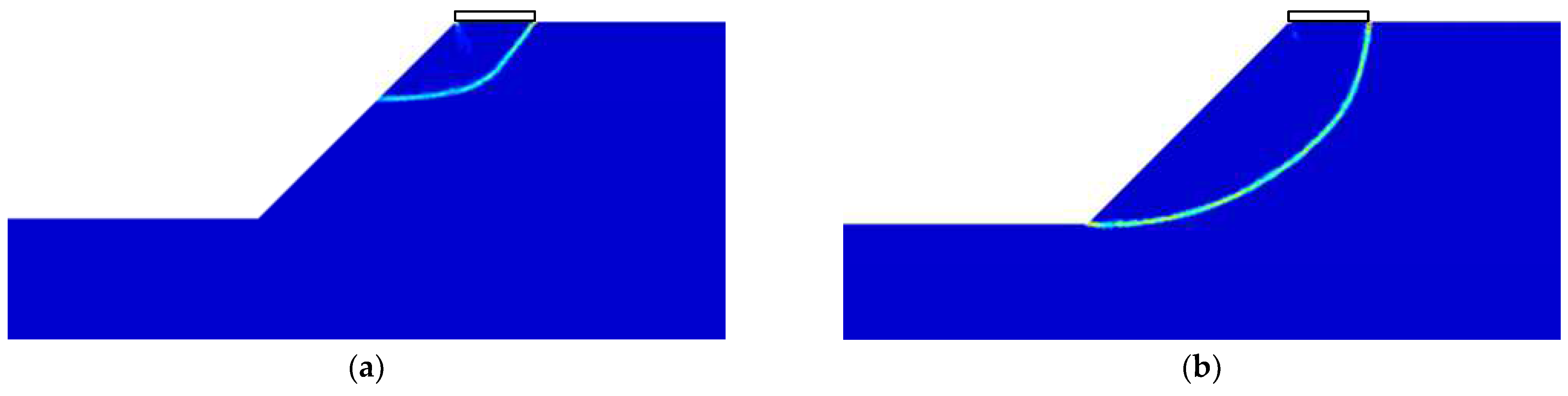
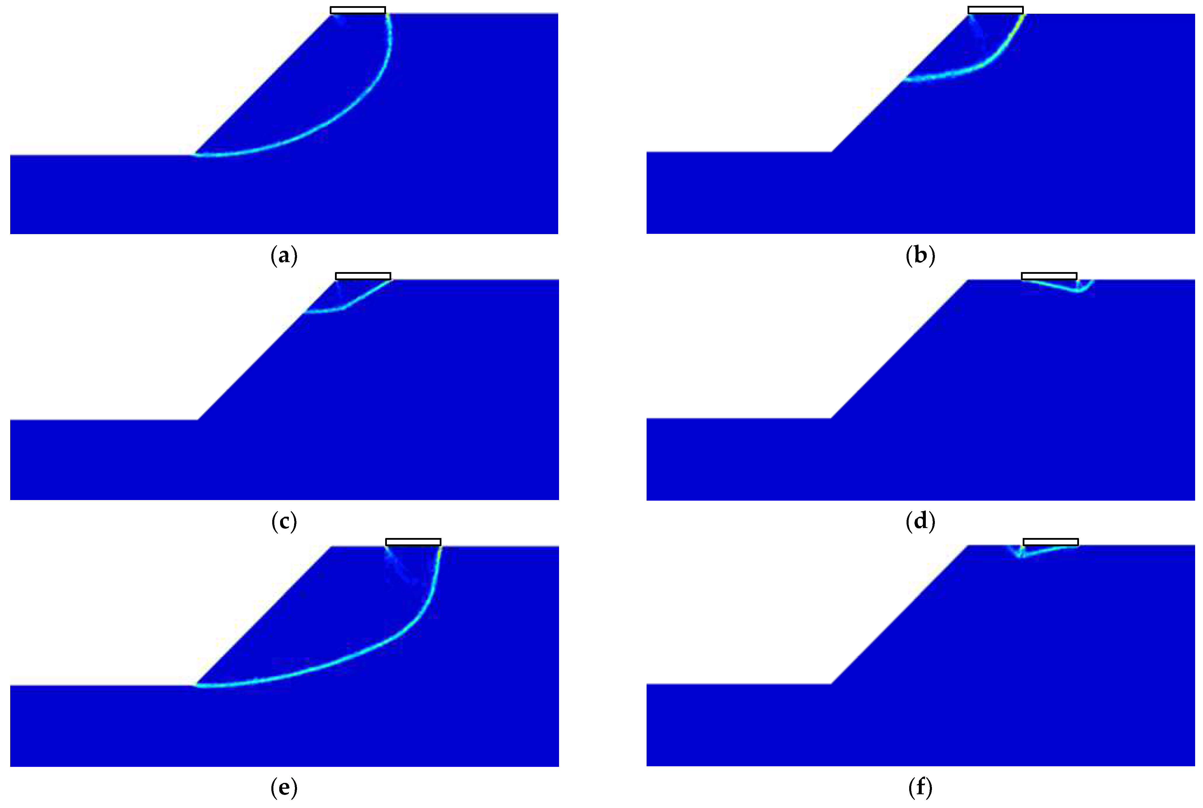
3.1.2. Failure Modes

The failure modes of different heterogeneous indices ρB/suc at re = 0.8, suc/γB = 1, L/B = 0, and θ = 90° are given in Figure 6. In this study, failure modes are presented in terms of shear dissipation using a rainbow spectrum, where blue and red represent the minimum and maximum values of shear dissipation, respectively. It can be seen that for ρB/suc = 0, the shear surface extends from the back corner point of the foundation to the slope face, which is defined as face failure mode by Zhou et al. (2018) [37]. The soil below the foundation forms an active wedge region, although it is not obvious. As ρB/suc increases, the soil strength increases linearly with depth, making the shear surface shallower and the active wedge region below the foundation more pronounced.
Figure 7 presents the failure modes for different anisotropic ratios re at ρB/suc = 0, suc/γB = 1, L/B = 0, and θ = 90°. It can be observed that when re = 1, the soil body undergoes face failure, and an active wedge region is formed below the foundation. When re decreases, the failure mode remains a face failure mode, but the shear surface becomes larger and closer to the toe of the slope, and the active wedge region is less pronounced. As re decreases further, e.g., re = 0.6, the soil body develops a toe failure mode [37].
The failure modes of different strength ratios suc/γB at re = 0.8, ρB/suc = 0, L/B = 0, and θ = 90° are given in Figure 8. When suc/γB = 2, face failure mode occurs in the soil body, and the shear surface extends to a larger area as suc/γB decreases. When suc/γB = 0.5, there are two shear surfaces extended upward from the toe of the slope, and the other ends of the shear surfaces are the corner point of the foundation and a point far away from the slope crest, respectively. In this scenario, the self-weight of the soil has a negative impact on the bearing capacity and can cause slope failure. There are two modes of slope failure: the toe failure mode and the overall slope failure mode. The toe failure mode in slope failure is different from the toe failure mode in bearing capacity failure, which is distinguished by whether there is a distinct active wedge and passive wedge.
The failure modes for different normalized foundation setbacks L/B at ρB/suc = 0, re = 1, suc/γB = 2, and θ = 90° are given in Figure 9. In cases where L/B is relatively large (e.g., L/B = 2.5), a typical Prandtl-type failure mode is evident. This suggests that the slope plays an insignificant role in determining the bearing capacity. As L/B decreases, the failure mode becomes asymmetric and there is a tendency for the shear surface to develop towards the slope. In cases where L/B is relatively small (e.g., L/B = 1), the slope plays a crucial role in determining the failure mode, which manifests as face failure. Additionally, the bearing capacity is observed to decrease as L/B becomes smaller.
Figure 10 presents the failure modes with different load angles θ at ρB/suc = 0, suc/γB = 1. For re = 0.8, L/B = 0, and 75° ≤ θ ≤ 105°, an increase in θ causes the shear surface to become shallower quickly, transitioning from toe failure to face failure mode. In cases where re = 1, L/B = 1, and θ = 90°, the shear surface extends from the foundation’s back corner to the slope toe, indicating a toe failure mode. When θ changes, whether increasing or decreasing, the failure mode is rapidly transformed into wedge mode [15]. It indicates that for such a scenario, the slope has an effect on the failure mode under vertical load but cannot affect the failure mode under inclined load. When θ is very large or very small (e.g., θ = 0° or 180°), the surface slip failure occurred. Overall, the effect of loading angle on the failure mode is significant regardless of the properties of the soil and the foundation setback.

3.2. MARS Results and Discussion

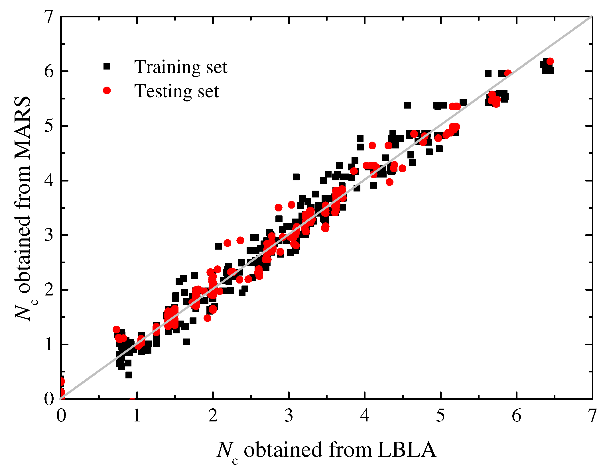
3.2.1. Model Performance

The results of the MARS analysis on the numerical model are presented, yielding an explicit empirical equation that includes 39 basis functions (including intercept). The nonlinear relationship between the five input parameters and the output is shown in Table 2. The predicted results of the MARS model were compared with the calculations from LBLA, as depicted in Figure 11. The dense scatter of points near the line of equality indicates a high degree of consistency between the MARS results and the FELA results. The training set achieves MAE, RMSE, and R2 values of 0.100, 0.153, and 0.986, respectively. In comparison, the testing set has slightly higher MAE and RMSE values of 0.112 and 0.169, with an R2 value of 0.983. This demonstrates that the MARS-based equation is an effective tool in practice.

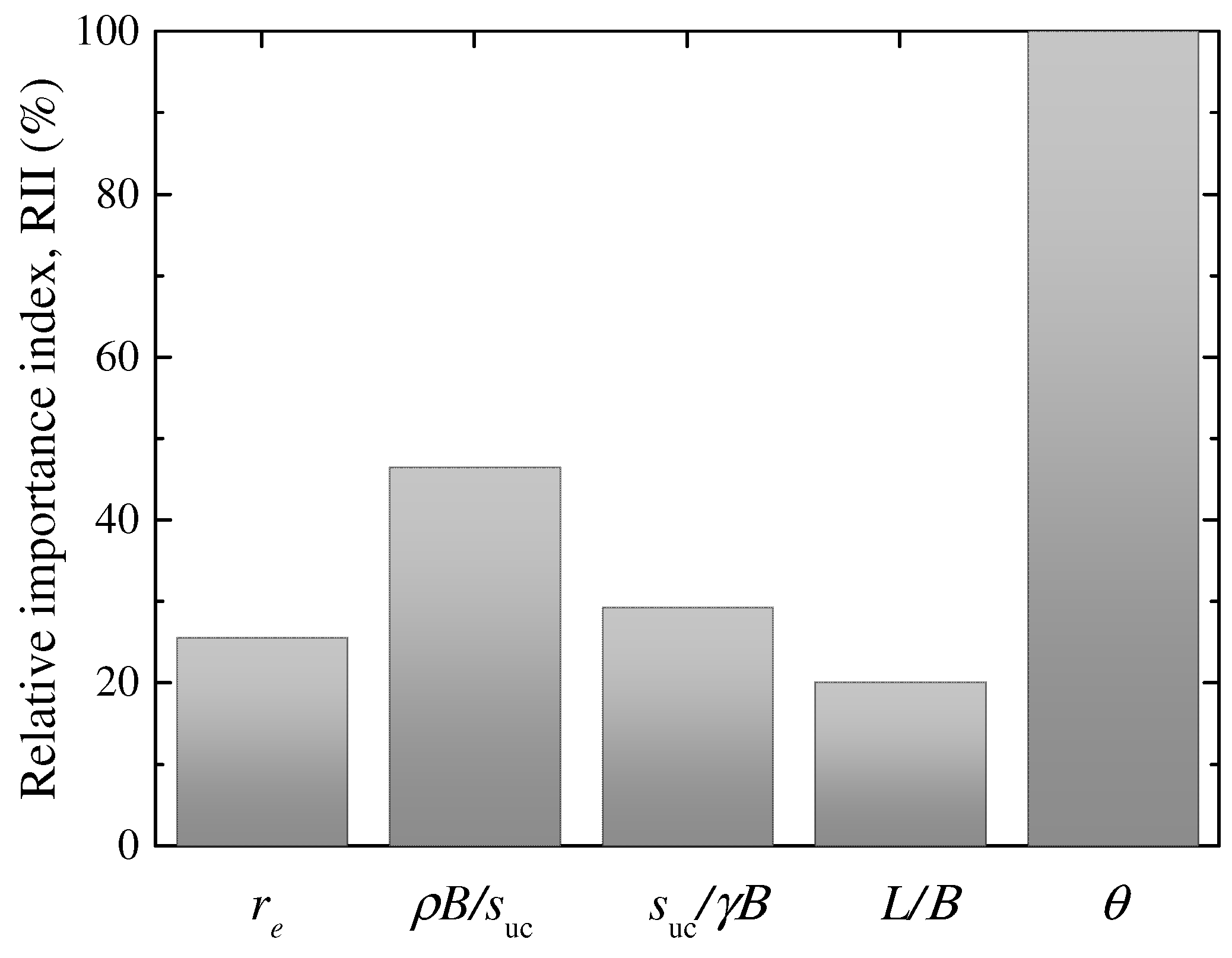
3.2.2. Feature Importance

The MARS model employs the relative importance index (RII) to evaluate the significance of each parameter. The RII is determined based on the increase in generalized cross-validation (GCV) values between the overfitting model and the pruned model. Figure 12 presents the outcomes of the relative importance study through RII values. Specifically, the RII values are as follows: re (25.58%), ρB/suc (46.46%), suc/γB (29.34%), L/B (20.10%), and θ (100%). A 100% RII value for the load angle θ underscores its status as the most influential parameter in determining the undrained bearing capacity. Additionally, the RII value of 46.46% for ρB/suc indicates that the heterogeneous index or strength gradient ratio is a significant factor in the slope’s bearing capacity. The parameters re and suc/γB are deemed to have moderate importance, whereas the significance of L/B is relatively minor.
The MARS results indicate that θ is the most significant variable, while the relative importance of L/B is the lowest. This finding provides actionable insights for practical engineering design: engineers should prioritize precise control of load inclination angles (e.g., through structural alignment or load redistribution) to maximize bearing capacity, particularly in marine environments where waves and currents induce complex loading directions. Additionally, sensitivity to θ necessitates incorporating dynamic load angle monitoring systems in critical offshore infrastructure to mitigate instability risks. It should be noted that the empirical equation from the MARS model inherently accounts for all variables’ interactions within the defined parameter ranges (Table 1). Engineers should adhere to these ranges to ensure model validity. Although L/B exhibits lower importance globally, its localized influence remains non-negligible in near-slope designs, necessitating holistic consideration of all parameters in practice.

4. Conclusions

This paper employs the lower bound limit analysis method to assess the undrained bearing capacity of foundations on slopes. The impact of various variables on bearing capacity and failure modes, including the normalized foundation setback (L/B), the load angle (θ), the strength ratio (suc/γB), the heterogeneous index (ρB/suc), and the anisotropy ratio (re), were considered. An empirical equation between bearing capacity and variables was derived using the MARS, and the performance of this algorithm was evaluated using multiple assessment indicators. Additionally, the importance of each variable was analyzed. The main conclusions are as follows:
(1)
Both normalized strength ratio ρB/suc and anisotropy ratio re exhibit positive correlations with bearing capacity factors, accompanied by failure mechanism transitions from deep-seated toe failure to shallow face failure patterns, evidenced by shear surface elevation.
(2)
The bearing capacity factor diminishes as the suc/γB decreases, which may potentially trigger failure mode transformation from localized bearing capacity failure to global slope instability. Both of these failure types include the toe failure mode, which can be distinguished based on the presence of distinct active and passive wedges.
(3)
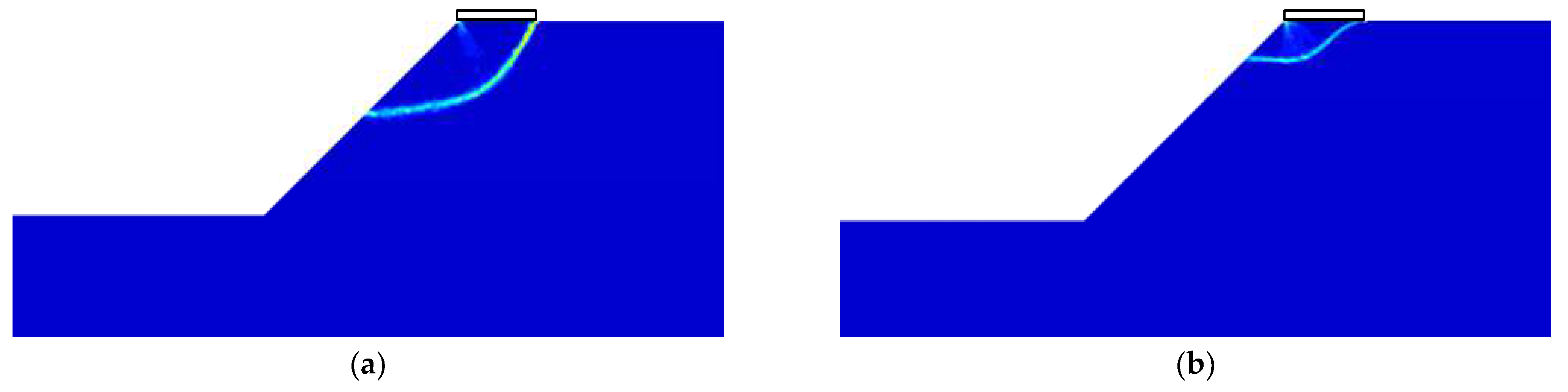
As the foundation moves away from the slope, the influence of the slope on the foundation diminishes, resulting in an increase in bearing capacity. The failure mode gradually transitions from face failure to the Prandtl-type failure.
(4)
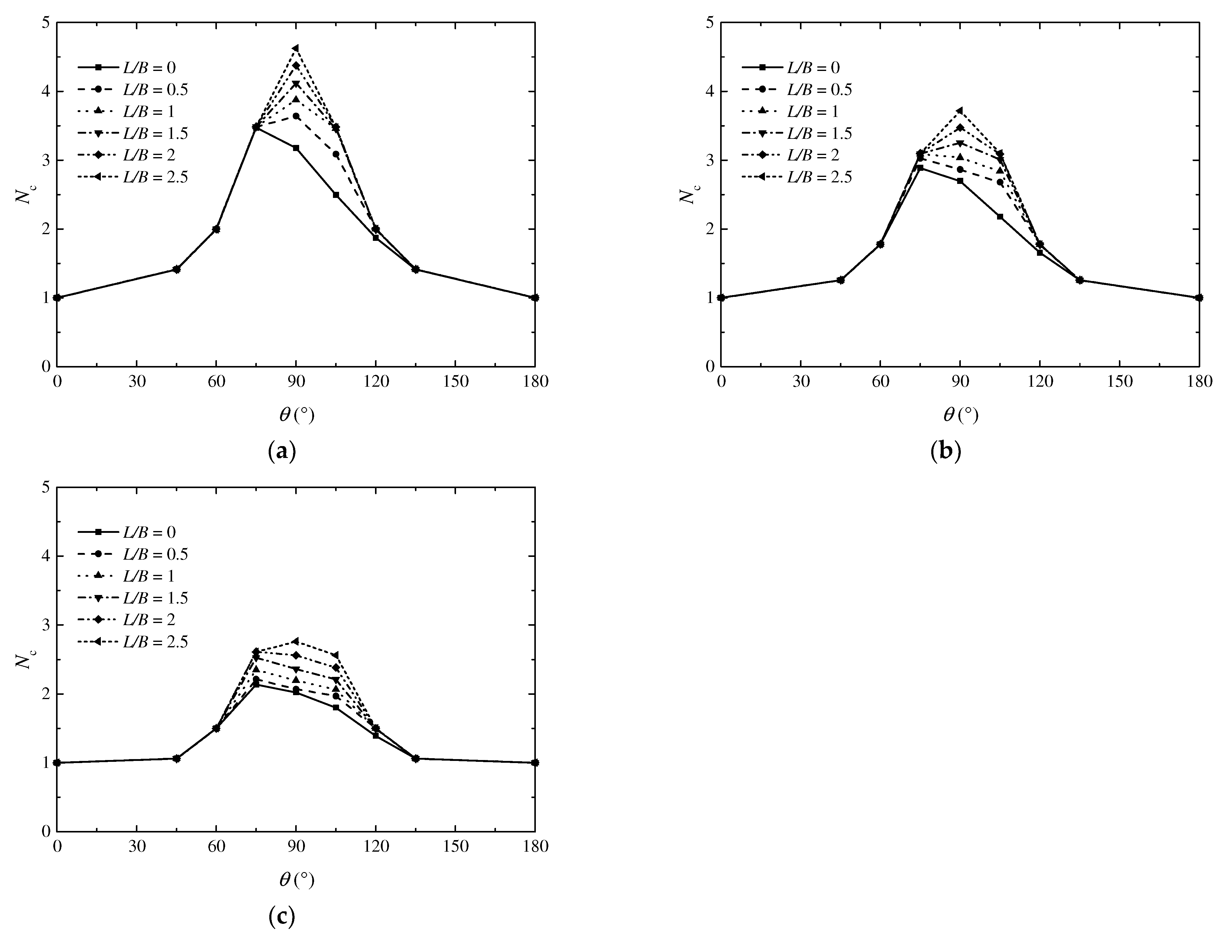
The foundation has the maximum bearing capacity when the load angle is between 75 and 90 degrees. As the angle increases or decreases further, the bearing capacity of the foundation decreases. Changes in the load angle significantly affect the failure mode of the foundation. It should be noted that the same load angle can cause significantly different failure modes under different soil conditions.
(5)
The MAE, RMSE, and R2 of the testing set obtained from the MARS are 0.112, 0.169, and 0.983, respectively, indicating that the empirical equation derived from MARS can reasonably predict the bearing capacity of foundations on anisotropic slopes. With the help of the RII (relative importance index), it is found that the load angle significantly affects the bearing capacity of the foundation, followed by ρB/suc, suc/γB, and re, while the influence of L/B is relatively lower. In practice, these variables are all very important and should not be overlooked.
This study provides a robust numerical framework for assessing undrained bearing capacity on anisotropic clay slopes, yet limitations remain. Experimental validation under marine conditions, particularly replicating anisotropic strength gradients, is challenging due to the complexity of seabed environments. Additionally, the current sensitivity analysis does not fully quantify nonlinear parameter interactions under stochastic variations. Future work will focus on (1) experimental validation through centrifuge or physical model tests to compare with numerical predictions and (2) advanced sensitivity analyses, such as one-at-a-time perturbations and Monte Carlo-based uncertainty assessments, to explore parameter interactions and failure mode transitions.

Author Contributions

Conceptualization, H.C.; methodology, H.C.; software, X.C.; validation, J.Z.; formal analysis, J.Z.; investigation, X.C.; resources, X.C.; data curation, J.Z.; writing—original draft preparation, X.C.; writing—review and editing, H.C.; visualization, X.C.; supervision, H.C.; project administration, X.C.; funding acquisition, X.C. All authors have read and agreed to the published version of the manuscript.

Funding

This research was funded by Natural Science Foundation of Shandong Province, China, grant number ZR2024QE120.

Data Availability Statement

The raw data supporting the conclusions of this article will be made available by the authors on request.

Acknowledgments

The third author acknowledges the support of the State Key Laboratory of Hydraulic Engineering Intelligent Construction and Operation, Tianjin University.

Conflicts of Interest

Author Jiang Zhu was employed by the Chifeng Construction Engineering Quality and Safety Technical Service Center, Inner Mongolia, China. The remaining authors declare that the research was conducted in the absence of any commercial or financial relationships that could be construed as potential conflicts of interest.

References

  1. Georgiadis, K. An upper-bound solution for the undrained bearing capacity of strip footings at the top of a slope. Géotechnique 2010, 60, 801–806. [Google Scholar] [CrossRef]
  2. Yang, S.; Leshchinsky, B.; Cui, K.; Zhang, F.; Gao, Y. Influence of failure mechanism on seismic bearing capacity factors for shallow foundations near slopes. Géotechnique 2021, 71, 594–607. [Google Scholar] [CrossRef]
  3. Lee, K.M.; Manjunath, V.R. Experimental and numerical studies of geosynthetic-reinforced sand slopes loaded with a footing. Can. Geotech. J. 2000, 37, 828–842. [Google Scholar] [CrossRef]
  4. Castelli, F.; Lentini, V. Evaluation of the bearing capacity of footings on slopes. Int. J. Phys. Model. Geotech. 2012, 12, 112–118. [Google Scholar] [CrossRef]
  5. Salih Keskin, M.; Laman, M. Model studies of bearing capacity of strip footing on sand slope. KSCE J. Civ. Eng. 2013, 17, 699–711. [Google Scholar] [CrossRef]
  6. Naeini, S.A.; Rabe, B.K.; Mahmoodi, E. Bearing capacity and settlement of strip footing on geosynthetic reinforced clayey slopes. J. Cent. South Univ. 2012, 19, 1116–1124. [Google Scholar] [CrossRef]
  7. Javdanian, H. On the behaviour of shallow foundations constructed on reinforced soil slopeA numerical analysis. Int. J. Geotech. Eng. 2017, 14, 188–195. [Google Scholar] [CrossRef]
  8. Satvati, S.; Alimohammadi, H.; Rowshanzamir, M.; Hejazi, S.M. Bearing Capacity of Shallow Footings Reinforced with Braid and Geogrid Adjacent to Soil Slope. Int. J. Geosynth. Ground Eng. 2020, 6, 41. [Google Scholar] [CrossRef]
  9. Farzaneh, O.; Askari, F.; Ganjian, N. Three-Dimensional Stability Analysis of Convex Slopes in Plan View. J. Geotech. Geoenviron. Eng. 2008, 134, 1192–1200. [Google Scholar] [CrossRef]
  10. Georgiadis, K. Undrained Bearing Capacity of Strip Footings on Slopes. J. Geotech. Geoenviron. Eng. 2010, 136, 677–685. [Google Scholar] [CrossRef]
  11. Shiau, J.S.; Merifield, R.S.; Lyamin, A.V.; Sloan, S.W. Undrained Stability of Footings on Slopes. Int. J. Geomech. 2011, 11, 381–390. [Google Scholar] [CrossRef]
  12. Hicks, M.A.; Nuttall, J.D.; Chen, J. Influence of heterogeneity on 3D slope reliability and failure consequence. Comput. Geotech. 2014, 61, 198–208. [Google Scholar] [CrossRef]
  13. Keshavarz, A.; Beygi, M.; Vali, R. Undrained seismic bearing capacity of strip footing placed on homogeneous and heterogeneous soil slopes by finite element limit analysis. Comput. Geotech. 2019, 113, 103094. [Google Scholar] [CrossRef]
  14. Jin, L.; Feng, Y.; Zhang, H.; Feng, Q. The use of improved radial movement optimization to calculate the ultimate bearing capacity of a nonhomogeneous clay foundation adjacent to slopes. Comput. Geotech. 2020, 118, 103338. [Google Scholar] [CrossRef]
  15. Bransby, M.F.; Randolph, M.F. Combined loading of skirted foundations. Géotechnique 1998, 48, 637–655. [Google Scholar] [CrossRef]
  16. Chen, H.; Shen, Z.; Wang, L.; Qi, C.; Tian, Y. Prediction of undrained failure envelopes of skirted circular foundations using gradient boosting machine algorithm. Ocean Eng. 2022, 258, 111767. [Google Scholar]
  17. Gao, Z.; Zhao, J.; Yao, Y. A generalized anisotropic failure criterion for geomaterials. Int. J. Solids Struct. 2010, 47, 3166–3185. [Google Scholar] [CrossRef]
  18. Tran, D.T.; Onjaipurn, T.; Kumar, D.R.; Chim-Oye, W.; Keawsawasvong, S.; Jamsawang, P. An eXtreme Gradient Boosting prediction of uplift capacity factors for 3D rectangular anchors in natural clays. Earth Sci. Inform. 2024, 17, 2027–2041. [Google Scholar] [CrossRef]
  19. Ladd, C.C. Stability Evaluation during Staged Construction. J. Geotech. Eng. 1991, 117, 540–693. [Google Scholar] [CrossRef]
  20. Won, J.Y. Anistropic strength ratio and plasiticty index of natural clays. In Proceedings of the 18th International Conference on Soil Mechanics and Geotechnical Engineering 2013, Paris, France, 2–6 September 2013; pp. 445–448. [Google Scholar]
  21. Casagrande, A.; Carillo, N. Shear failure of anisotropic materials. J. Boston Soc. Civ. Eng. 1944, 31, 74–87. [Google Scholar]
  22. Davis, E.H.; Christian, J.T. Bearing capacity of anisotropic cohesive soil. J. Soil. Mech. Found. Div. 1971, 97, 753–769. [Google Scholar] [CrossRef]
  23. Prevost, J.H. Undrained shear tests on clay. J. Soil Mech. Found. Div. 1979, 105, 49–64. [Google Scholar] [CrossRef]
  24. Krabbenhøft, K.; Galindo-Torres, S.A.; Zhang, X.; Krabbenhøft, J. AUS: Anisotropic undrained shear strength model for clays. Int. J. Numer. Anal. Methods Geomech. 2019, 43, 2652–2666. [Google Scholar] [CrossRef]
  25. Lai, V.Q.; Chenari, R.J.; Banyong, R.; Keawsawasvong, S. Undrained Stability of Opening in Underground Walls in Anisotropic Clays. Int. J. Geomech. 2023, 23, 06022042. [Google Scholar] [CrossRef]
  26. Zhang, C.; Chen, M. Prediction of Undrained Shear Strength Utilizing a Hybrid Stacking Model Enhanced by Bayesian Optimization Algorithm. Transp. Res. Rec. 2024. [Google Scholar] [CrossRef]
  27. Duong, N.T.; Shiau, J.; Keawsawasvong, S.; Lai, V.Q. Three-dimensional undrained stability analysis of circular tunnel heading in anisotropic and heterogeneous clay: FELA, ANN, MARS, and XGBoost. Model. Earth Syst. Environ. 2024, 10, 5503–5527. [Google Scholar] [CrossRef]
  28. Friedman, J.H. Multivariate adaptive regression splines. Ann. Stat. 1991, 19, 1–67. [Google Scholar] [CrossRef]
  29. Zhou, H.; Diao, Y.; Zheng, G.; Han, J.; Jia, R. Failure modes and bearing capacity of strip footings on soft ground reinforced by floating stone columns. Acta Geotech. 2017, 12, 1089–1103. [Google Scholar] [CrossRef]
  30. Zhang, W.; Zhang, Y.; Goh, A.T.C. Multivariate adaptive regression splines for inverse analysis of soil and wall properties in braced excavation. Tunn. Undergr. Space Technol. 2017, 64, 24–33. [Google Scholar] [CrossRef]
  31. Lai, V.Q.; Shiau, J.; Keawsawasvong, S.; Tran, D.T. Bearing Capacity of Ring Foundations on Anisotropic and Heterogenous Clays: FEA, NGI-ADP, and MARS. Geotech. Geol. Eng. 2022, 40, 3913–3928. [Google Scholar] [CrossRef]
  32. Krabbenhoft, K.; Lyamin, A.V. Generalised Tresca criterion for undrained total stress analysis. Geotech. Lett. 2015, 5, 313–317. [Google Scholar] [CrossRef]
  33. Kumar, D.R.; Samui, P.; Wipulanusat, W.; Keawsawasvong, S.; Sangjinda, K.; Jitchaijaroen, W. Soft-Computing Techniques for Predicting Seismic Bearing Capacity of Strip Footings in Slopes. Buildings 2023, 13, 1371. [Google Scholar] [CrossRef]
  34. Ke, L.; Gao, Y.; Zhao, Z.; Zhou, Y.; Ji, J. Undrained Bearing Capacity of Strip Footing near Slopes Considering the Orientation of Strength Increase. Int. J. Geomech. 2021, 21, 06021016. [Google Scholar] [CrossRef]
  35. Mukhopadhyay, T. A multivariate adaptive regression splines based damage identification methodology for web core composite bridges including the effect of noise. J. Sandw. Struct. Mater. 2017, 20, 885–903. [Google Scholar] [CrossRef]
  36. Zheng, G.; Zhang, W.; Zhou, H.; Yang, P. Multivariate adaptive regression splines model for prediction of the liquefaction-induced settlement of shallow foundations. Soil Dyn. Earthq. Eng. 2020, 132, 106097. [Google Scholar] [CrossRef]
  37. Zhou, H.; Zheng, G.; Yin, X.; Jia, R.; Yang, X. The bearing capacity and failure mechanism of a vertically loaded strip footing placed on the top of slopes. Comput. Geotech. 2018, 94, 12–21. [Google Scholar] [CrossRef]
Figure 1. Schematic diagram of the foundation on an anisotropic clay slope.
Jmse 13 00681 g001
Figure 2. Numerical model and its adaptive meshes.
Jmse 13 00681 g002
Figure 3. Comparison of the results of this study and previous studies [10,34].
Jmse 13 00681 g003
Figure 4. Variation of Nc with re, suc/γB and (a) ρB/suc = 1; (b) ρB/suc = 0.5; (c) ρB/suc = 0.
Jmse 13 00681 g004
Figure 5. Variation of Nc with L/B, θ and (a) re = 1; (b) re = 0.8; (c) re = 0.6.
Jmse 13 00681 g005
Figure 6. Failure modes for re = 0.8, suc/γB = 1, L/B = 0, θ = 90°, and (a) ρB/suc = 0; (b) ρB/suc = 1.
Jmse 13 00681 g006
Figure 7. Failure modes for ρB/suc = 0, suc/γB = 1, L/B = 0, θ = 90° and (a) re = 1; (b) re = 0.6.
Jmse 13 00681 g007
Figure 8. Failure modes for re = 0.8, ρB/suc = 0, L/B = 0, θ = 90° and (a) suc/γB = 2; (b) suc/γB = 0.5.
Jmse 13 00681 g008
Figure 9. Failure modes for ρB/suc = 0, re = 1, suc/γB = 2, θ = 90° and (a) L/B = 2.5; (b) L/B = 1.
Jmse 13 00681 g009
Figure 10. Failure modes for ρB/suc = 0, suc/γB = 1, and (a) θ = 75°, re = 0.8, L/B = 0; (b) θ = 90°, re = 0.8, L/B = 0; (c) θ = 105°, re = 0.8, L/B = 0; (d) θ = 75°, re = 1, L/B = 1; (e) θ = 90°, re = 1, L/B = 1; (f) θ = 105°, re = 1, L/B = 1.
Jmse 13 00681 g010
Figure 11. A comparison of the results from LBLA and MARS approaches.
Jmse 13 00681 g011
Figure 12. Relative importance index for each parameter.
Jmse 13 00681 g012
Table 1. Parameters of a foundation on a clay slope.
ParametersInput Values
Normalized foundation setback, L/B0, 0.5, 1, 1.5, 2, and 2.5
Load angle, θ0°, 45°, 60°, 75°, 90°, 105°, 120°, 135° and 180°
Strength ratio, suc/γB0.5, 1, 1.5, and 2
Heterogeneous index, ρB/suc0, 0.5, and 1
Anisotropic ratio, re0.6, 0.8, and 1
Table 2. BFs and the empirical equations for Nc.
BFEquationBFEquation
BF1max(0, θ − 90)BF20BF8 × max(0, ρB/suc − 0.5)
BF2max(0, re − 0.8)BF21BF8 × max(0, 0.5 − ρB/suc)
BF3max(0, 0.8 − re)BF22max(0, 0.5 − L/B) × max(0, θ − 75)
BF4max(0, 0.5 − ρB/suc)BF23max(0, 105 − θ)
BF5BF4 × max(0, 40 − suc/γB)BF24max(0, θ − 105) × max(0, 0.8 − re)
BF6BF4 × max(0, θ − 105)BF25max(0, 90 − θ) × max(0, re − 0.8)
BF7BF4 × max(0, 105 − θ)BF26max(0, 90 − θ) × max(0, 0.8 − re)
BF8max(0, θ − 60)BF27max(0, ρB/suc − 0.5) × max(0, θ − 75)
BF9max(0, 60 − θ)BF28max(0, ρB/suc − 0.5) × max(0, 75 − θ)
BF10max(0, 90 − θ) × max(0, ρB/suc − 0.5)BF29BF7 × max(0, suc/γB − 40)
BF11max(0, 90 − θ) × max(0, 0.5 − ρB/suc)BF30BF7 × max(0, 40 − suc/γB)
BF12max(0, 120 − θ)BF31BF12 × max(0, re − 0.8)
BF13BF5 × max(0, re − 0.8)BF32BF12 × max(0, 0.8 − re)
BF14BF5 × max(0, 0.8 − re)BF33BF12 × max(0, ρB/suc − 0.5)
BF15max(0, L/B − 0.5)BF34BF12 × max(0, 0.5 − ρB/suc)
BF16max(0, 0.5 − L/B) × max(0, θ − 90)BF35max(0, θ − 120) × max(0, L/B − 0.5)
BF17BF11 × max(0, suc/γB − 40)BF36max(0, θ − 120) × max(0, 0.5 − L/B)
BF18BF11 × max(0, 40 − suc/γB)BF37max(0, 90 − θ) × max(0, L/B − 1.5)
BF19BF6 × max(0, 40 − suc/γB)BF38max(0, 90 − θ) × max(0, 1.5 − L/B)
Note: The empirical equation for the bearing capacity factor Nc = −3.1579 − 0.22093 × BF1 + 0.95808 × BF2 − 1.6304 × BF3 + 5.1162 × BF4 − 0.18811 × BF5 + 0.1033 × BF6 − 0.22348 × BF7 + 0.19144 × BF8 − 0.11878 × BF9 − 0.1226 × BF10 + 0.23974 × BF11 + 0.05774 × BF12 + 0.23958 × BF13 − 0.2586 × BF14 + 0.10946 × BF15 + 0.22489 × BF16 − 0.0023504 × BF17 + 0.0085555 × BF18 + 0.0050284 × BF19 − 0.018043 × BF20 − 0.11055 × BF21 − 0.14707 × BF22 + 0.029787 × BF23 + 0.020441 × BF24 − 0.12663 × BF25 + 0.12085 × BF26 + 0.02184 × BF27 + 0.068415 × BF28 + 0.0016585 × BF29 − 0.0037492 × BF30 + 0.069736 × BF31 − 0.063212 × BF32 + 0.046004 × BF33 − 0.03263 × BF34 − 0.0073116 × BF35 − 0.086122 × BF36 − 0.0035574 × BF37 + 0.0021242 × BF38.
Disclaimer/Publisher’s Note: The statements, opinions and data contained in all publications are solely those of the individual author(s) and contributor(s) and not of MDPI and/or the editor(s). MDPI and/or the editor(s) disclaim responsibility for any injury to people or property resulting from any ideas, methods, instructions or products referred to in the content.

