Article

Degradation Characteristics and Mechanisms of Steel Fiber-Reinforced Concrete Linings in Subsea Tunnels: Insights from Accelerated Erosion Tests with Applied Electric Fields

1
CCCC Second Highway Consultants Co., Ltd., Wuhan 430056, China
2
CCCC Research and Development Center on Tunnel and Underground Space Technology, Wuhan 430056, China
3
Institute of Geotechnical and Underground Engineering, Shandong University, Jinan 250061, China
4
School of Engineering and Technology, China University of Geosciences (Beijing), Beijing 100083, China
5
Shandong Earthquake Agency, Jinan 250014, China
*
Author to whom correspondence should be addressed.
J. Mar. Sci. Eng. 2025, 13(4), 670; https://doi.org/10.3390/jmse13040670
Submission received: 25 February 2025 / Revised: 24 March 2025 / Accepted: 25 March 2025 / Published: 26 March 2025
(This article belongs to the Section Ocean Engineering)

Abstract

:
Understanding the long-term durability and degradation mechanisms of steel fiber-reinforced concrete (SFRC) linings in subsea tunnels is critical for ensuring structural safety, cost effectiveness, and sustainability. This study investigated the degradation characteristics of SFRC with varying fiber contents (0%, 0.35%, 0.55%, and 0.75%) and different acceleration durations, using the applied electric field acceleration method and X-ray CT tests. The experimental results revealed the characteristics of the surface crack distribution and evolution patterns in the SFRC specimens. Furthermore, the similarity between the non-uniform corrosion patterns observed in regard to accelerated corrosion under the applied electric fields and those occurring due to natural degradation was verified. The pore structure characteristics and internal crack development of the SFRC specimens were compared. The study found that the degradation process of the specimens was closely related to the fiber content. The incorporation of steel fibers altered the crack initiation and propagation modes, leading to a more scattered crack distribution. The accelerated corrosion method, employing an applied electric field, successfully simulated the non-uniform corrosion process of reinforcement in SFRC linings in subsea tunnels under natural conditions. Under the influence of a unidirectional chloride ingress source, the pronounced accumulation of corrosion products was observed only on the side of the reinforcement exposed to chloride penetration. This method effectively visualized the chloride penetration path and its impact on reinforcement corrosion, providing valuable insights for the anti-corrosion design of SFRC linings in subsea tunnels.

1. Introduction

Subsea tunnels, as critical transportation infrastructure across straits, require structural materials with excellent anti-corrosion properties to resist the long-term corrosion of concrete matrices and reinforcement caused by chlorides and other corrosive agents in seawater. As the scale and demands of subsea tunnel construction increase, the chloride corrosion resistance and structural degradation mechanisms of concrete linings have become major concerns for experts and researchers [1,2]. As the operational lifespan of existing subsea tunnels increases, the durability of such structures in regard to the degradation of reinforced concrete linings has become more important due to the influence of the corrosive marine environment, unfavorable geological conditions, and the application of dynamic loads during operation [3,4]. Due to the combined effects of multiple factors, such as the exposure to chlorides, high water pressure, and carbonation [5,6], the durability of subsea tunnel concrete linings faces severe challenges, and carrying out repairs becomes increasingly difficult once damage has occurred [7]. Countries such as the United Kingdom and Japan, which constructed subsea tunnels earlier than other countries, incur high annual costs to repair structural damage caused by durability degradation.
SFRC, known for its superior tensile strength, toughness, and crack inhibition performance, has been widely used in the construction of primary support and permanent linings in tunnel projects worldwide [8,9]. Researchers and engineers have conducted extensive studies on the mechanical properties and structural stability of tunnels constructed using conventional SFRC, steel fiber-reinforced self-compacting concrete (SFRSCC) [10,11], ultra-high performance fiber-reinforced concrete (UHPFRC) [12], and steel fiber-reinforced sprayed concrete (SFRSC) [13]. The influence mechanisms of the fiber composition, shape, size, and content on the mechanical properties of different types of SFRC have been revealed [14,15]. The volumetric content of steel fibers, in particular, directly affects the pore structure of the concrete matrix. An appropriate fiber content ensures good workability, allowing the steel fibers to function effectively without compromising the pore structure [16]. However, compared to studies on the mechanical properties of the materials and the structural stability of tunnels [5,17,18], research on the long-term durability and degradation behavior of SFRC linings in subsea tunnels in corrosive marine environments is relatively scarce [19]. This is due to the fact that investigating the long-term corrosion behavior of SFRC typically requires longer durations [20]. Some studies have directly used pre-corroded steel fibers to investigate the material properties of SFRC, but the results obtained through the use of this method remain controversial [21]. Song et al. [21] accelerated the experimental process using a direct current and a constant current method, effectively evaluating the corrosion risk of UHPFRC with initial micro-defects. Frazao et al. [10] employed a similar method to study the degradation mechanisms of SFRSCC, observing slight spalling of the protective layer due to fiber corrosion. Feng et al. [22] used a scientifically effective structural simplification and accelerated corrosion method, concluding that the use of steel fibers improved the internal structure of the concrete and delayed the initial rusting time of the reinforcement. Some researchers have also adopted soaking or salt spray wet–dry cycle methods to accelerate the degradation of concrete components [23,24], but the experimental duration required is significantly longer than that of the impressed current method [25]. Notably, most current studies focus on SFRC specimens without rebar reinforcement, and there is limited research on the degradation mechanisms caused by long-term exposure to chloride attack in concrete materials containing both rebar and steel fibers [26].
The limited research on the long-term corrosion performance of SFRC linings in subsea tunnels means that an understanding of the degradation mechanisms is incomplete, restricting the broader application of steel fibers in this context. Thus, scientifically designed accelerated corrosion methods to be used in laboratories are essential for simulating the long-term corrosion and damage behavior of SFRC, thereby revealing its degradation characteristics and mechanisms [27]. Researchers have focused on the similarity between rebar corrosion patterns in laboratory-accelerated tests and natural environments [28,29]. The most common impressed current method used in laboratory tests treats the reinforcement as an electrode, resulting in a uniform corrosion pattern after accelerated corrosion. However, as subsea tunnel concrete linings are only exposed to seawater on one side, the chloride source is unidirectional. Therefore, the reinforcement in subsea tunnel concrete lining undergoes non-uniform corrosion, with the thickness of the corrosion products on the chloride-exposed side being considerably greater than on the opposite side [30,31]. To better approximate the natural corrosion pattern, some researchers have proposed an innovative method that involves embedding a stainless steel wire near one side of the reinforcement to accelerate corrosion [32]. In regard to this method, the positive terminal of the external electric field is connected to the rebar and the negative terminal is connected to the stainless steel wire. Upon applying a direct current, the distribution of corrosion products obtained through this approach more closely resembles that of natural corrosion [33]. While this method has successfully induced non-uniform corrosion in concrete without steel fibers [34], its applicability to SFRC remains uncertain and requires further investigation. On the other hand, researchers, such as Tang et al. [35,36] at Chalmers University of Technology, have proposed the well-known CTH method for the rapid testing of chloride migration coefficients in concrete. This method applies an electric field at both ends of the concrete specimen, establishing a stable potential difference between an external anode and an external cathode to accelerate the migration of chloride ions in the concrete matrix [37].
This study investigated the degradation characteristics and mechanisms of SFRC linings in subsea tunnels through the use of an accelerated corrosion experiment with an externally applied electric field. SFRC specimens with varying fiber volume fractions were tested to assess the effects of different acceleration durations and steel fiber contents. Visual inspection and X-ray CT tests were conducted to analyze the distribution and evolution patterns of surface cracks. The experimental results demonstrated the spatial distribution of the chloride ion concentration and the variation in steel reinforcement corrosion rates in SFRC under different accelerated deterioration cycles. This study also compared the influence of steel fiber inclusion on the pore structure and internal crack development in concrete. Additionally, the similarity between corrosion patterns induced by an electric field and those from natural degradation was confirmed.

2. Experimental Program

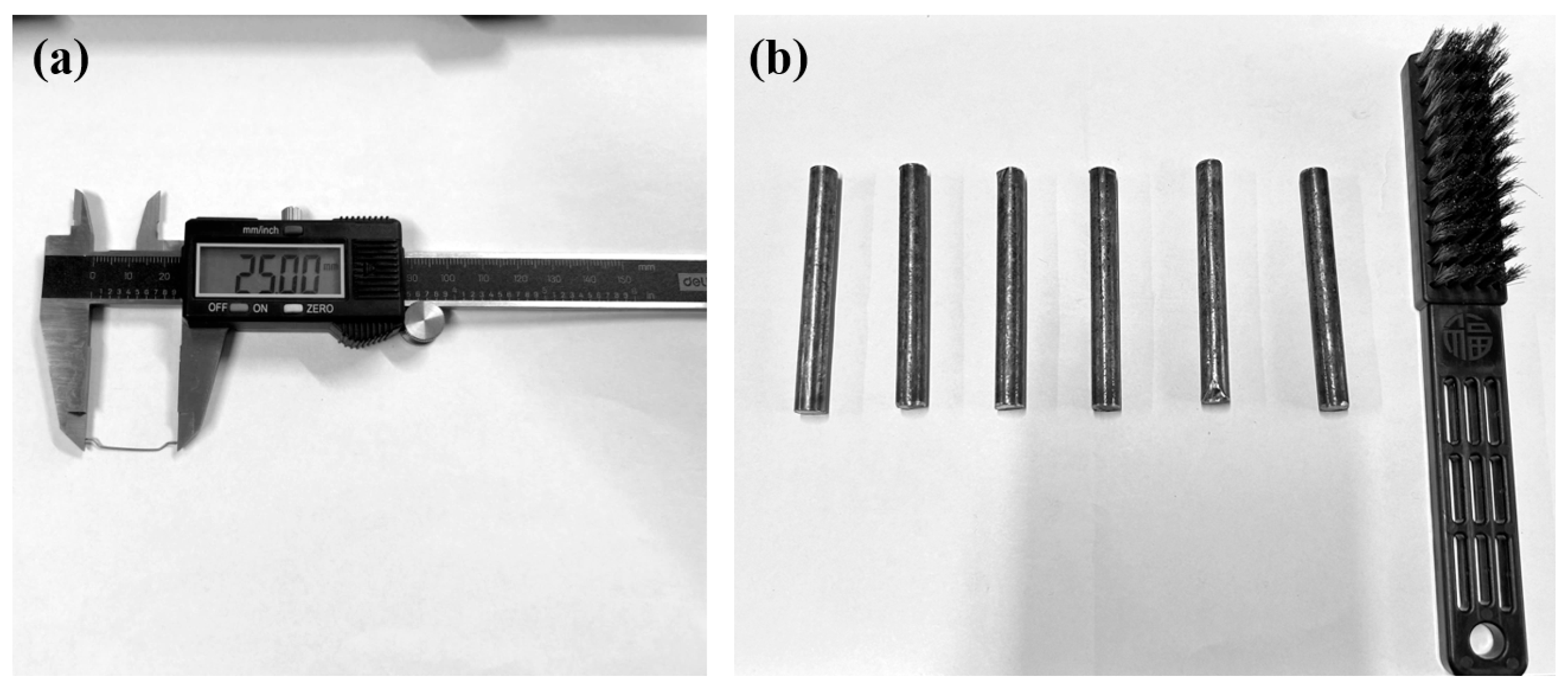
2.1. Materials and Mix Design

The SFRC mix consists of P·I 52.5 Portland cement (PC), pulverized fuel ash (PFA), slag powder (SP), sand (SA), crushed stone (CS), polycarboxylate-based superplasticizer (PC), tap water (W), steel fibers (SF), and rebars. As shown in Figure 1, the steel fibers used in this study are hook ended with a diameter of 0.5 mm, a length of 25 mm, and a tensile strength of 1100 MPa. To examine the effect of the steel fiber content on the degradation performance of the linings, four different steel fiber volume fractions (0%, 0.35%, 0.55%, and 0.75%) were selected for the experiment. The rebar used was an ordinary smooth rebar, model HPB300 (Qingdao Huaou Group Sihai New Building Materials Co., Ltd., Qingdao, China), with a diameter of 8 mm. Before the accelerated corrosion test, each rebar was cleaned with a soft steel wire brush.
The concrete grades commonly used for the secondary lining of currently constructed subsea tunnels include C45 and C50. In this study, the concrete mix design was based on the specifications of the Jiaozhou Bay Second Subsea Tunnel project in Qingdao, China. The specific mix proportions for the SFRC are presented in Table 1. The compressive strength of the concrete specimens without steel fibers reached 45.5 MPa at 7 days and 84.6 MPa at 28 days, with a slump of 190 mm.

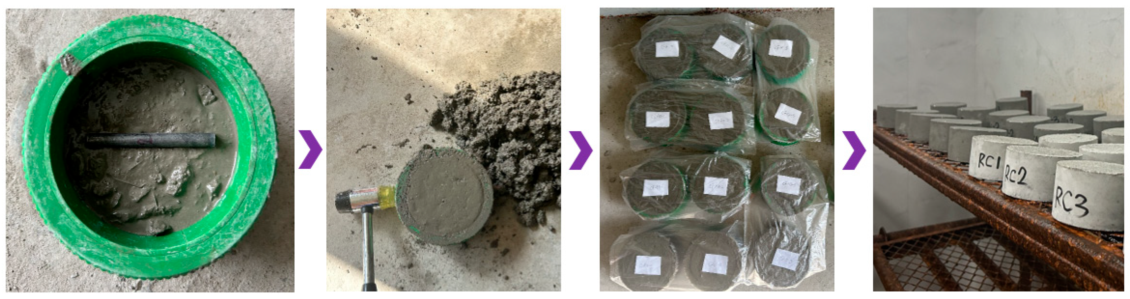
2.2. SFRC Specimen Preparation

The weighed steel fibers were evenly dispersed and thoroughly mixed into the concrete to ensure uniform distribution. A cylindrical mold (100 mm in diameter and 50 mm in height) was used, with a release agent uniformly applied to the mold surface. Using concrete specimens of this size for accelerated corrosion tests helps shorten the chloride penetration path and improve the testing efficiency. Additionally, in regard to X-ray CT tests, this size ensures a high scanning resolution, while retaining sufficient internal concrete structure information. The specimen size is compatible with the accelerated corrosion testing equipment, facilitating test operations. The specimen preparation process is illustrated in Figure 2. First, the SFRC was poured into the mold, filling it to a height of approximately 2.5 cm, at which point a steel bar was placed into the center of the mold. The mold was then further filled with SFRC, and the outer side of the mold was struck with a rubber mallet. Finally, the upper surface was leveled using vibrations, excess material was removed, and the surface was smoothed with a trowel, ensuring that the height difference between the specimen surface and the mold edge remained within 0.5 mm. The surface of the reinforced concrete specimen was covered with plastic film, and the specimens were numbered. After resting at room temperature for 1 day, the molds were removed, and the specimens were placed in a curing room for standard curing. The curing room temperature was maintained at 20 ± 2 °C, with a relative humidity of over 95%.

2.3. Accelerated Corrosion Scheme Using an External Electric Field
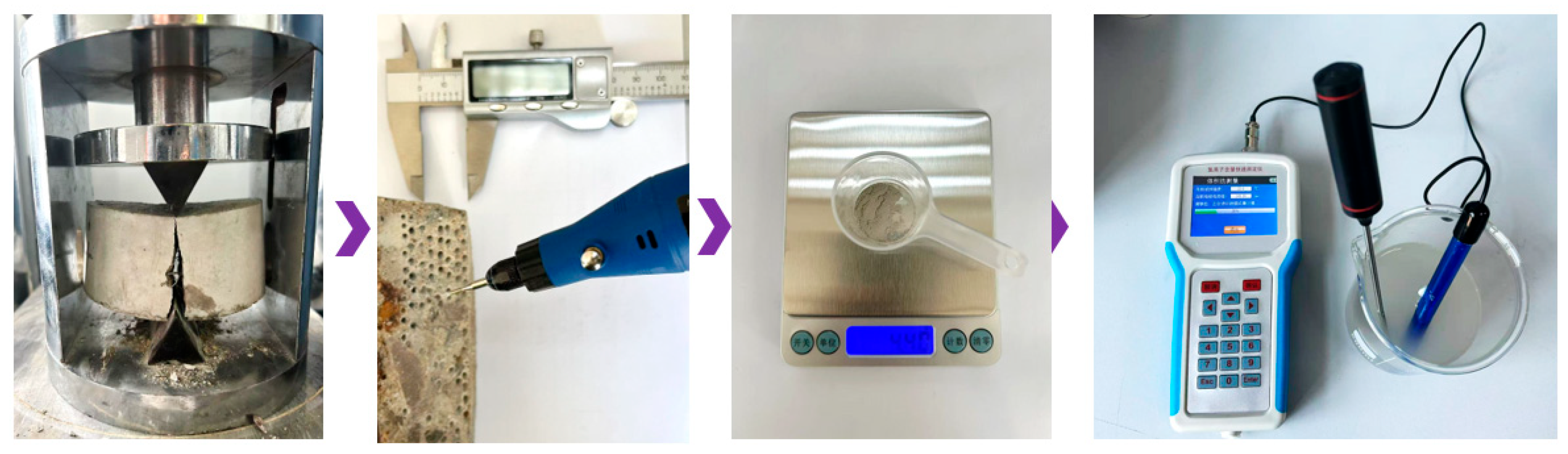
The accelerated corrosion testing procedure using an external electric field is shown in Figure 3. First, the cured specimens undergo vacuum saturation. The specimens are then placed at the bottom of a rubber sleeve, with two stainless steel clamps secured around it at the same height as the specimen to ensure a proper seal on the cylindrical sides. The rubber sleeve containing the specimen is placed at a 30 degree angle inside the plastic testing tank, with the anode and cathode plates properly positioned. The anode and cathode solutions are prepared using 0.3 M NaOH and 10% NaCl (by mass), respectively. Once the specimen is set up, a 60 V voltage is applied between the external anode and cathode to accelerate chloride ion transport. To achieve different levels of specimen degradation, the external electric field is applied for 0 h, 24 h, 40 h, and 56 h. Based on the preliminary test results, accelerated deterioration exceeding 60 h would result in a substantial accumulation of corrosion products on the specimen surface and the expansion of the specimen sleeve, which may affect the interpretation of the test results. A 16 h interval leads to noticeable differences in the deterioration states. Therefore, representative time points were selected to capture varying degrees of deterioration. Additionally, specimens subject to 0 h of degradation were set as the control group.

2.4. X-Ray CT Test

X-ray CT is a nondestructive testing technique widely used in materials science, medicine, and engineering to obtain three-dimensional images of internal structures. In this study, X-ray CT was employed to analyze the pore structure characteristics during the accelerated corrosion of subsea tunnel SFRC linings. X-ray CT testing offers the advantages of being intuitive, precise, and nondestructive in the study of the concrete pore structure. Additionally, X-ray CT data can be processed using image processing techniques to extract parameters such as porosity and pore size distribution, enabling precise quantification of the concrete pore structure. During scanning, X-rays are directed at the specimen from a single direction, penetrating and attenuating as they pass through. Different materials attenuate X-rays to varying degrees, depending on their density, thickness, and composition. Various regions within the specimen, including the steel fibers, aggregates, and pores, exhibit different X-ray absorption levels, resulting in distinct attenuation effects [38]. After scanning, the results undergo segmentation, evaluation, and visualization. After grayscale rendering, high-density regions appear lighter, whereas lower density pores appear black in the images. In this study, a YXLON precision CT scanner from Germany was used, with an applied X-ray tube voltage of 300 kV, a power of 100 W, and a resolution of 50 μm.

2.5. Chloride Ion Concentration and Steel Corrosion Rate Testing

After the X-ray CT test, the specimen was split in half at the midpoint, using a pressure machine. Next, as shown in Figure 4, a small grinder with a 3 mm drill bit was used to grind the specimen cross-section at a uniform depth. Concrete powder samples were collected by combining material from multiple drilled holes at the same depth. A brush was used during sampling to remove larger insoluble particles and minimize their interference with the test results. The collected powder was weighed and transferred into a beaker. Distilled water was added to the beaker until a total volume of 300 mL was reached, followed by thorough stirring. Finally, the chloride ion concentration was measured using a rapid chloride ion tester, based on the ion-selective electrode method. Simultaneously, after splitting the specimen, the embedded steel bars were extracted and subjected to acid pickling. The corrosion rate of the steel bars was determined by measuring the mass difference before and after the accelerated corrosion test.

3. Results and Discussion

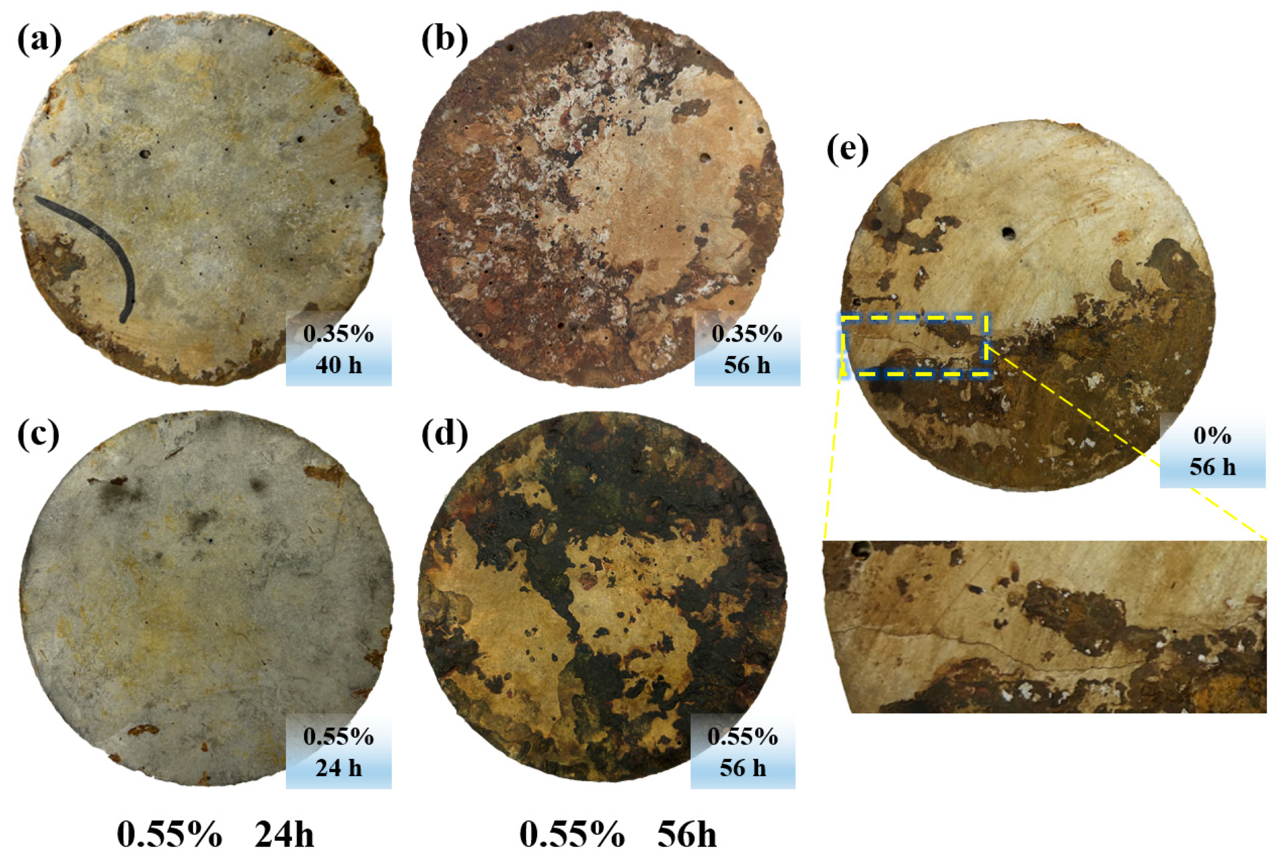
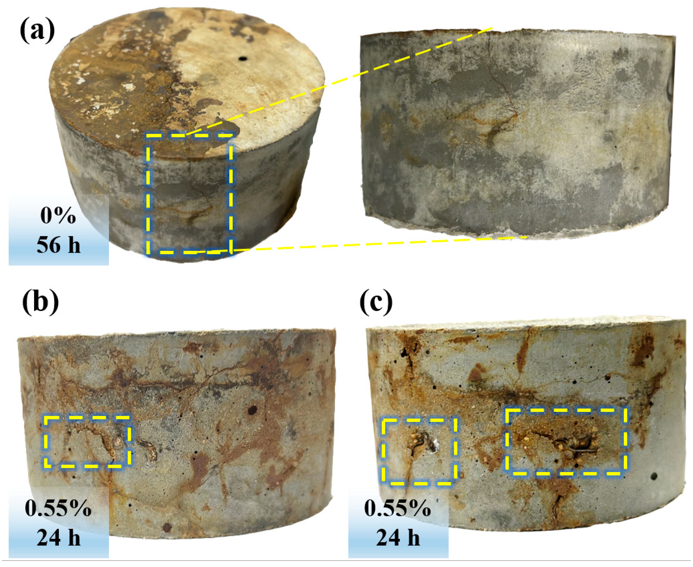
3.1. Distribution Characteristics and Evolutionary Patterns of Surface Rust Expansion Cracks

Figure 5 illustrates the accumulation of corrosion products and the distribution of surface cracks on the anode side of the specimens after different durations of accelerated corrosion. In Figure 5a, the surface of a specimen containing 0.35% of steel fiber content is shown after 40 h of exposure to an external electric field. Corrosion product deposition is observed at the specimen’s outer contour, but no visible cracks are apparent on the surface. As shown in Figure 5c, for a specimen with 0.55% of steel fiber content, after 24 h of exposure to an external electric field, no significant changes are observed on the specimen’s surface, and no accumulation of corrosion products is present.
However, as the duration of the exposure to the electric field increased, more noticeable changes appeared on the surface of the SFRC specimens. Figure 5e shows a specimen without steel fibers after 56 h of exposure to an external electric field, where distinct through cracks are observed on the surface, accompanied by the deposition of corrosion products. The corrosion products are deposited along the cracks, forming rust spots on the specimen’s surface. These rust spots are brown in color and cover approximately half of the specimen’s surface area. Figure 5b,d shows specimens with steel fiber contents of 0.35% and 0.55%, respectively. It can be seen that after 56 h of accelerated corrosion, no through cracks appeared on the anode side of the specimens containing steel fibers. The steel fibers distributed within the protective layer alleviated the expansion pressure caused by the corrosion products, delaying the formation and propagation of cracks. Thus, the steel fibers played a role in hindering the development of cracks in the protective layer. However, the specimens with steel fibers showed marked accumulation of corrosion products, and the coverage area of the corrosion products was larger than that of the specimen without steel fibers.
The corrosion products of the SFRC specimen with a 0.55% volume fraction of steel fibers were the darkest in color, followed by the specimen with 0.35% of steel fibers, while the specimen without steel fibers exhibited the lightest color.
The presence of steel fibers increased the total metallic surface area within the specimen, generating more iron ions during the electrochemical corrosion process and leading to a larger area of corrosion product deposition on the surface. The main components of the corrosion products may include Fe(OH)3 and Fe2O3. A higher steel fiber content intensified the corrosion process, producing denser corrosion products and resulting in a darker color.
Figure 6 compares the crack distribution patterns on the side surfaces of the specimens with steel fiber contents of 0% and 0.55%. For the specimen without steel fibers, cracks appeared on the side surface, connecting with the cracks on the upper surface, accompanied by the deposition of corrosion products. The maximum visible crack length on the specimen’s side reached approximately 36 mm. It is hypothesized that the side cracks appeared at the ends of the reinforcing bars, and the relative positioning of the cracks in regard to the reinforcing bars will be analyzed in subsequent sections. After 24 h of accelerated corrosion subject to the electric field, the specimen with a steel fiber content of 0.55% showed noticeable deterioration on the side surface. Although no cracks connected to the upper and lower surfaces of the specimen were observed, small, scattered cracks appeared. The maximum visible crack length on the specimen’s side reached approximately 21 mm. Additionally, slight spalling occurred, with some severely spalled areas, even exposing the internal steel fibers. The distribution of corrosion products was also scattered. On average, four minor spalling areas were observed on each specimen’s side, with an average spalling area of 46 mm2. The specimen without steel fibers exhibited high crack connectivity and the concentrated distribution of corrosion products, indicating a faster degradation process. In contrast, the specimen with steel fibers displayed scattered cracks, a relatively slower degradation rate, and more pronounced localized corrosion.

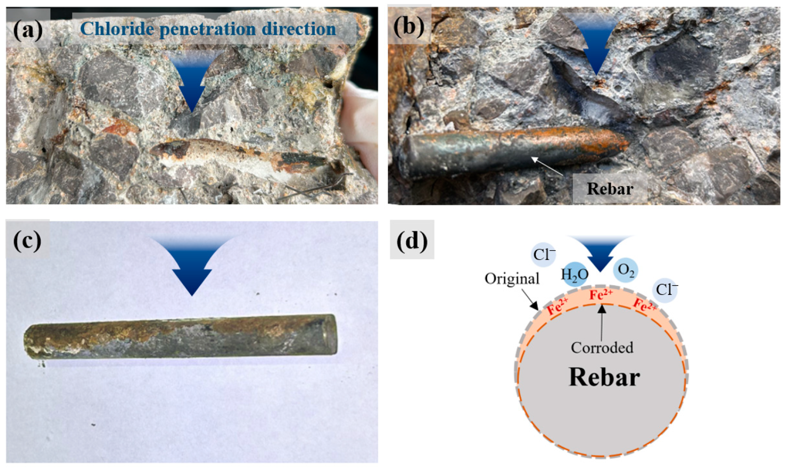
3.2. Non-Uniform Corrosion Patterns of Reinforcing Bars and Steel Fibers

In practical engineering, only one side of the concrete lining in subsea tunnels is exposed to seawater corrosion, with chloride ingress occurring in a directional manner. Consequently, in natural conditions, the thickness of corrosion products on the reinforcing bars of the concrete lining is non-uniform, with corrosion products primarily accumulating on the side facing the chloride source (Figure 7d). In laboratory conditions, accurately simulating this non-uniform corrosion pattern is crucial for understanding the accelerated corrosion mechanism of SFRC linings in subsea tunnels.
Figure 7 shows the split SFRC specimens and the corroded reinforcing bars extracted from them. The results indicate that the accelerated corrosion method and device used in this study effectively simulated the non-uniform corrosion pattern in natural conditions. Due to the influence of unidirectional chloride ingress, visible corrosion product accumulation occurred only on the side of the reinforcing bars facing the chloride source. Furthermore, after the reinforcing bars were extracted from the concrete matrix, some corrosion products remained adhered to the concrete (Figure 7a). These corrosion products exhibited a certain physical or chemical adhesive force at the interface between the corrosion layer and the concrete matrix, causing them to remain in the concrete even after the steel bars were removed. Figure 7c provides a clearer visualization, showing that the corrosion products accumulated on the upper half of the reinforcing bar’s cross-section, while the lower half largely retained its original appearance. The corrosion behavior of the reinforcing bars in the SFRC specimens is significantly influenced by the chloride ion diffusion path and concentration gradient.
Figure 8 shows the corrosion patterns of the steel fibers in the cross-section of the SFRC specimens after splitting. It is evident that the corrosion of the steel fibers is also non-uniform, meaning that corrosion does not occur evenly across the fibers. This is observed from the rust spots left by the steel fiber corrosion in Figure 8a and the exposed steel fibers in Figure 8b. The corrosion of hooked-end steel fibers predominantly occurs at the hooked ends, a phenomenon reported in previous studies. A possible explanation is that the interface bond strength between the steel fibers and the concrete varies at different locations, with lower bond strength or micro-gaps at the hooked ends, making them more susceptible to corrosion initiation. Additionally, hooked-end steel fibers are typically manufactured through cold bending, a process that induces significant plastic deformation at the hooked ends, resulting in pronounced stress concentrations and potential microstructural changes.

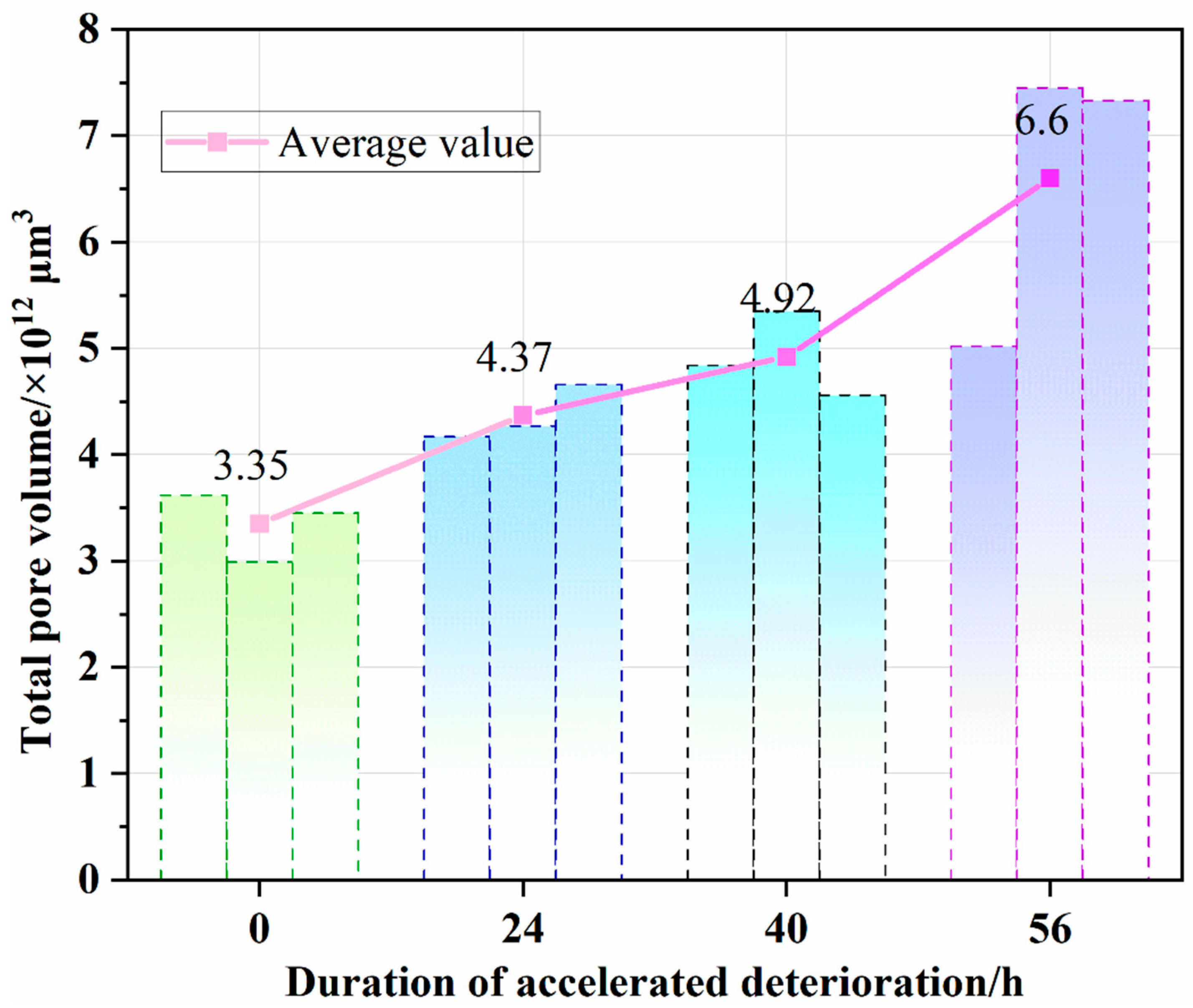
3.3. Characteristics and Evolution of Pore Structure

Figure 9 presents the 3D imaging of the SFRC specimen obtained from the X-ray CT testing. Figure 9a shows the distribution of the steel fibers and reinforcement within the specimen, where the steel fibers are observed to be uniformly dispersed in the concrete matrix. In Figure 9b, the pore structure of the specimen is highlighted in different colors, while the steel fibers and reinforcement are displayed in gray. It can be seen that the corrosion products of the reinforcement are only present in the lower half of the cross-section (the dark green region in Figure 9b), indicating a distinct non-uniform corrosion pattern. This further confirms the similarity to the non-uniform corrosion mode discussed in the previous section. Meanwhile, it was observed that the steel fibers used in this study did not exhibit significant agglomeration. However, considering the application of steel fibers in subsea tunnel engineering, both the fiber incorporation method and the concrete pumping process can influence the distribution of steel fibers. The formation of agglomerated regions may result in larger pores, facilitating the penetration of water, chloride ions, and other aggressive agents, thereby accelerating the corrosion of the reinforcement and compromising the long-term service performance of the lining structure. On the other hand, steel fiber agglomeration can also affect construction processes by reducing the workability of the concrete mixture, increasing construction difficulty, and potentially leading to localized areas of insufficient compaction, ultimately diminishing the durability of the structure.
Figure 10 illustrates the trend of pore volume variation in the SFRC specimens with a steel fiber volume fraction of 0.55% under accelerated corrosion. The initial average total pore volume of the SFRC specimens was approximately 3.35 × 1012 μm3. After 24 h of external electric field degradation, the total pore volume increased to about 4.37 × 1012 μm3, a 30.45% increase. After 56 h of accelerated corrosion, the average pore volume reached 6.6 × 1012 μm3. This indicates that the intrusion by chloride ions, moisture, and oxygen accelerated through the cracks, further corroding the reinforcing bars and steel fibers, generating more corrosion products and expansion cracks, which caused the porosity to continue to increase. The micro-cracks gradually expanded, increasing the local porosity and enhancing pore structure connectivity, thereby facilitating faster penetration of corrosive media. As the corrosion intensified, the expansion stress further widened the micro-cracks, which eventually developed into macro-cracks. The increased connectivity and width of these cracks significantly altered the overall pore structure of the specimens. When cracks penetrated the protective layer of the concrete specimen, the original pore structure was replaced by cracks, leading to a substantial increase in porosity, which severely reduced the specimens’ impermeability and mechanical performance. An increase in porosity may allow corrosive substances, such as chloride ions, to penetrate more easily into the concrete, especially in the presence of chlorides, where the presence of steel fibers may accelerate corrosion, thereby reducing the durability and load-bearing capacity of the concrete. The reduced durability could lead to structural safety issues, particularly in regard to critical infrastructure like subsea tunnels. Therefore, the use of SFRC in subsea tunnel projects requires more stringent protective measures, such as the application of anti-corrosion coatings or the use of more corrosion-resistant steel. Additionally, regular inspections of the tunnel’s concrete structure, particularly in high-risk areas like entrances and exits, should be conducted to promptly identify and repair damage caused by corrosion.
Additionally, Figure 11 presents the distribution of pores of different sizes in the specimens after 24 h and 56 h of accelerated corrosion subject to an external electric field. The expansion of corrosion products and changes in the internal stress within localized materials collectively drive the dynamic evolution of the pore structure. It can be observed that as the duration of accelerated corrosion increases, the proportion of large pores (>100 mm3) in the SFRC increases from 28.17% to 40.03%, while the proportion of pores in the range of 10–100 mm3 decreases from 15.15% to 10.37%. Some medium-sized pores gradually transition into large pores due to their connectivity with other pores or the expansion of micro-cracks, leading to a reduction in their proportion. The increase in the proportion of large pores and the reduction in medium-sized pores significantly enhanced the permeability of the concrete, making it easier for corrosive ions, moisture, and other harmful substances to penetrate, thereby accelerating the rusting of the reinforcement and the deterioration of the concrete. The reduction in medium-sized pores indicates a deterioration of the internal pore structure of the concrete, with increased pore connectivity, further reducing the concrete’s density and impermeability. The deterioration of the pore structure provides more pathways for chemical erosion, accelerating the chemical corrosion of the concrete. Furthermore, the proportion of pores in the 0.01–0.1 mm3 range increases slightly from 6.43% to 6.77%. The slight increase in this pore size range may be due to the relatively slow growth rate of smaller pores, with some original pores remaining within this range during the expansion process.

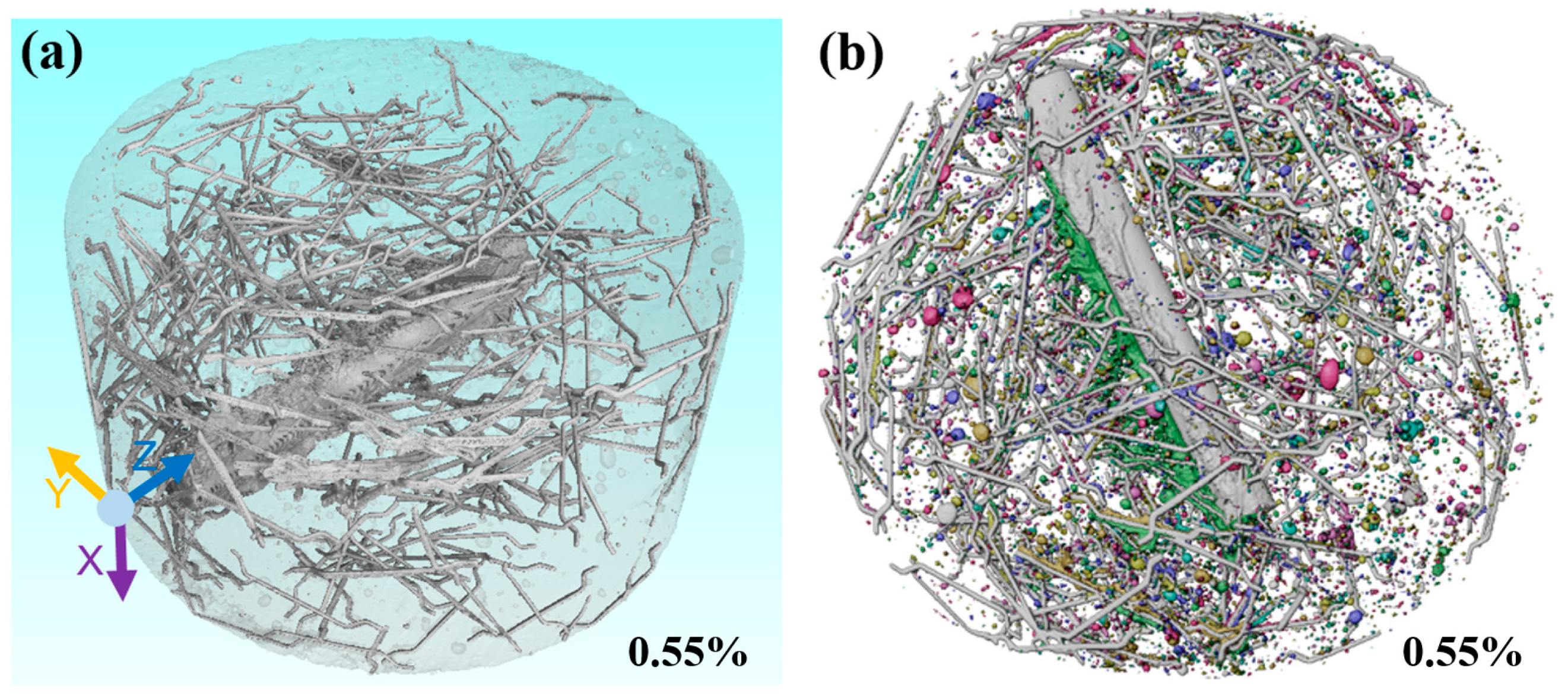
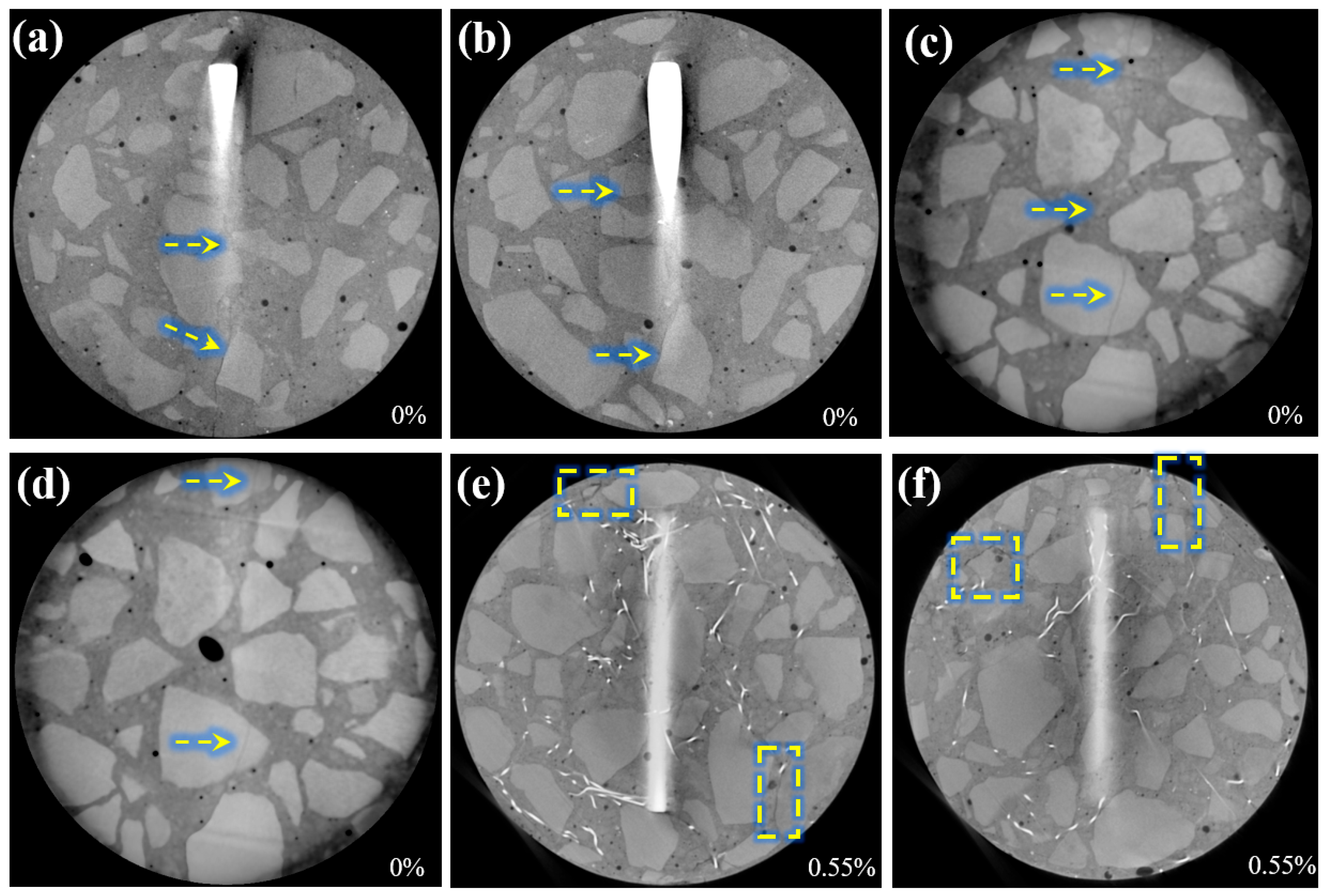
3.4. Internal Crack Distribution Characteristics and Development Pattern

X-ray tomography imaging followed by slicing reveals the development pattern of internal cracks at different locations. Figure 12 presents slices parallel to the bottom surface of the specimen (YZ plane), illustrating the progression of rust-induced cracks near the steel rebar. In the grayscale rendering, regions with higher density appear lighter: black represents pores, gray represents the matrix, and white represents the rebar and steel fibers.
Figure 12a–d shows that in the steel-reinforced concrete specimen without steel fibers, a primary crack is present in the protective layer. Combined with the surface cracks shown in Section 3.1, these cracks extend through the rebar and reach the side of the specimen. Additionally, as the slice moves closer to the rebar, a secondary crack appears on the left side of the rebar (Figure 12b). As the slices move away from the rebar, the distance between the primary and secondary cracks gradually increases. Meanwhile, the secondary cracks become shorter and no longer extend to the specimen surface. The primary crack extends along the side of the specimen to the bottom surface and connects with the radial crack on the specimen’s bottom surface. The cracks run parallel to the rebar, penetrating both sides and the bottom surface of the specimen, and are almost aligned in the same vertical plane as the rebar axis.
Figure 12e,f illustrates the development pattern of internal cracks in the protective layer of the SFRC specimens. Even after 56 h of accelerated deterioration, no through cracks caused by rebar rust expansion appear in the specimen’s protective layer. However, due to the influence of randomly distributed steel fibers, scattered cracks are observed at the edges of the specimen, with crack lengths limited to approximately 6–25 mm. The further development of these cracks is constrained by the steel fibers, and some cracks extend along the interface between the aggregates and the concrete matrix. It is foreseeable that edge cracks may lead to the spalling of the protective layer. The primary role of the steel fibers is to bridge the cracks and limit their expansion. In areas without fiber distribution, cracks propagate more easily due to the absence of obstructions along their path, leading to the formation of visible cracks. In contrast, in regions with dense steel fiber distribution, cracks are dispersed or interrupted due to the bridging effect of the fibers. This highlights the importance of ensuring a uniform distribution of steel fibers during the construction phase through proper mixing and pouring techniques to effectively control rust-induced cracks.

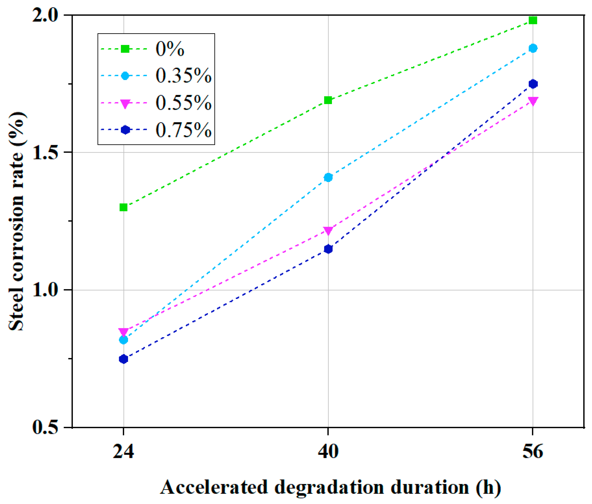
3.5. Distribution Characteristics of Chloride Ion Concentration and Steel Corrosion Rate

Figure 13 presents the average chloride ion concentration profiles along the depth of the concrete specimens with different steel fiber contents after 40 h of accelerated corrosion. The chloride ion concentration is expressed as a percentage of the total weight of the concrete powder. It can be observed that the steel fiber content has little effect on the chloride ion concentration in the surface layer of the exposed concrete. Within the top 10 mm, the chloride ion concentration ranges between 0.6% and 0.72%.
As the depth increases, the chloride ion concentration in the specimen with 0.75% of steel fiber content decays first, with a sharp decline occurring between 27 mm and 36 mm. Ultimately, at a depth of 36 mm, the chloride ion concentration drops below 0.04%. The chloride ion concentration profiles of the specimens with 0.35% and 0.55% of steel fiber content exhibit similar trends, but the depth at which the concentration decay occurs is greater than that of the 0.75% specimen. This indicates that the SFRC specimen with a steel fiber content of 0.75% has better resistance to chloride ion penetration compared to those with 0.35% and 0.55% of steel fiber content. For the plain concrete specimen without steel fibers, the chloride ion concentration exhibits the longest duration to decay, with a sharp decline observed between 36 mm and 42 mm. This suggests that the incorporation of steel fibers enhances the resistance of the concrete to chloride ion penetration.
Furthermore, after accelerated deterioration, the corrosion products on the embedded steel reinforcement were removed through acid cleaning, and the corrosion rate curve of the steel bars was obtained based on the mass loss of the reinforcement (averaged over three specimens). As shown in Figure 14, the corrosion rate of the steel reinforcement exhibited an almost linear variation with the applied electric field cycles. With an increasing number of deterioration cycles, the progressive degradation of the concrete pore structure provided more pathways for chloride ion ingress, thereby accelerating the corrosion of the steel reinforcement. The specimens without steel fibers exhibited the highest corrosion rate. After 56 h of accelerated electrochemical corrosion, the corrosion rate of the reinforcement in the plain concrete specimens reached approximately 1.98%, which was about 1.17 times that of the specimens with a steel fiber content of 0.55%. The steel reinforcement in the SFRC specimens with steel fiber contents of 0.35%, 0.55%, and 0.75% exhibited superior corrosion resistance compared to that of the plain concrete specimens. The presence of steel fibers contributed to the improvement of the internal concrete structure by reducing the connectivity of the pores, thereby reducing the corrosion rate of the steel reinforcement. Additionally, the presence of steel fibers may influence the electrochemical environment within the concrete, alter the local current distribution, and suppress the corrosion reaction of the steel reinforcement.

4. Conclusions

This study investigates the degradation characteristics of SFRC with different steel fiber contents (0%, 0.35%, 0.55%, and 0.75%) under varying accelerated aging durations, using an accelerated corrosion method, based on an external electric field and X-ray CT tests. The following conclusions are drawn from this work:
(1)
The degradation process of the specimens is closely related to the steel fiber content. The specimens without steel fibers exhibit a high level of crack connectivity, and the corrosion products are concentrated. The addition of steel fibers can delay crack formation; however, an excessively high fiber content may intensify the localized accumulation of corrosion products. Specimens without steel fibers are more prone to forming penetrating cracks, facilitating the rapid diffusion of corrosive media. The incorporation of steel fibers alters the crack initiation and propagation patterns, resulting in a more dispersed crack distribution. Therefore, optimizing the steel fiber content requires balancing the crack resistance and corrosion resistance;
(2)
The accelerated corrosion method using an external electric field successfully simulates the non-uniform corrosion process of the reinforcement in SFRC linings in undersea tunnels in natural conditions. Due to the ingress of chloride ions on one side, corrosion products accumulated only on the surface of the chloride-infiltrated side. This method effectively demonstrates the chloride corrosion path and its impact on reinforcement corrosion, providing valuable insights for anti-corrosion design in practical engineering. Furthermore, the corrosion of hooked-end steel fibers predominantly occurs at the hooked ends;
(3)
As the accelerated corrosion duration increases, the proportion of large pores in SFRC increases from 28.17% to 40.03%, while the proportion of medium-size pores (10–100 mm3) decreases. As a result of the accelerated corrosion induced by the external electric field, some medium-sized pores connect with other pores and gradually expand into large-sized pores;
(4)
In ordinary reinforced concrete specimens without steel fibers, the main crack penetrates the protective layer. Secondary cracks appear around the steel bars, but do not reach the surface. In contrast, after 56 h of degradation of SFRC specimens, no through-cracks are formed. Instead, short cracks (6–25 mm) appear only at the edges, demonstrating the effective crack-bridging role of steel fibers. Future research should focus on comparing the similarities and differences between deterioration cracks and structural cracks;
(5)
Concrete specimens without steel fibers exhibited the deepest chloride ion penetration and the poorest resistance to corrosion. The incorporation of steel fibers effectively enhanced the resistance of concrete to chloride ion ingress. The corrosion rate of the steel reinforcement was influenced by the applied electric field, the pore structure of the concrete, and the steel fiber content. An appropriate amount of steel fiber improved the concrete structure, reduced chloride ion permeability, and enhanced the corrosion resistance of the steel reinforcement, thereby delaying the corrosion process.

Author Contributions

Conceptualization, L.W. and H.G.; methodology, L.W., J.L. and H.G.; validation, H.S. and Q.C.; formal analysis, H.S., W.P. and M.H.; investigation, L.W. and H.G.; resources, J.L. and H.G.; data curation, J.L. and Y.X.; writing—original draft preparation, J.L., L.W., H.G. and Y.X.; writing—review and editing, Q.C., H.S. and W.P.; visualization, H.G. and M.H.; supervision, L.W. and H.G.; project administration, L.W. All authors have read and agreed to the published version of the manuscript.

Funding

This research was funded by the Key Program of CCCC (No. 2022-ZJKJ-10 and No. 2024-ZJKJ-04).

Data Availability Statement

The original contributions presented in this study are included in the article, further inquiries can be directed to the corresponding author.

Conflicts of Interest

Authors Longhai Wei, Jiguo Liu, Heng Shu, Qinglong Cui, and Wenbo Peng were employed by the company CCCC Second Highway Consultants Co., Ltd. The remaining authors declare that the research was conducted in the absence of any commercial or financial relationships that could be construed as a potential conflict of interest.

References

  1. Manquehual, C.J.; Jakobsen, P.D.; Holter, K.G.; De Weerdt, K.; Danner, T.; Bruland, A. Comparison of the condition of steel fiber-reinforced shotcrete with water-glass and alkali-free activators after more than 20 years of service in a subsea road tunnel. Constr. Build. Mater. 2022, 328, 127090. [Google Scholar] [CrossRef]
  2. Ju, X.L.; Wu, L.J.; Liu, M.W.; Jiang, H.; Zhang, W.X. Modelling of Chloride Concentration Profiles in Concrete by the Consideration of Concrete Material Factors under Marine Tidal Environment. J. Mar. Sci. Eng. 2022, 10, 26. [Google Scholar] [CrossRef]
  3. Sun, Z.Y.; Zhang, D.L.; Fang, Q. Technologies for large cross-section subsea tunnel construction using drilling and blasting method. Tunn. Undergr. Space Technol. 2023, 141, 105161. [Google Scholar] [CrossRef]
  4. Gong, H.M.; Xue, Y.G.; Fu, K.; Kong, F.M.; Han, M.; Zhou, B.H.; Guo, Y.B. Assessing and predicting surrounding rock settlement troughs in the subsea tunnel: A case study of Haicang Tunnel. Mar. Georesources Geotechnol. 2024, 1–12. [Google Scholar] [CrossRef]
  5. Li, P.F.; Wang, F.; Long, Y.Y.; Zhao, X. Investigation of steady water inflow into a subsea grouted tunnel. Tunn. Undergr. Space Technol. 2018, 80, 92–102. [Google Scholar] [CrossRef]
  6. Sun, Z.Y.; Zhang, D.L.; Fang, Q. Determination Method of Reasonable Reinforcement Parameters for Subsea Tunnels Considering Ground Reinforcement and Seepage Effect. Appl. Sci. 2019, 9, 21. [Google Scholar] [CrossRef]
  7. He, Z.S.; He, C.; Kang, X.Y.; Huang, X.; Wang, S.M. Assessment of structural performance of super large cross-section subsea RC shield tunnels: Emphasis on the combined effects of highly hydrostatic pressure and corrosion-induced deterioration. Ocean Eng. 2023, 288, 15. [Google Scholar]
  8. Horny, U.; Bayer, L.; Schiesser, K.; Kliem, O. Metro Doha Green Line: Fibre reinforced tunnel linings—Design and construction experience. Geomech. Tunn. 2021, 14, 347–355. [Google Scholar]
  9. Manquehual, C.J.; Jakobsen, P.D.; Holter, K.G.; De Weerdt, K.; Bruland, A. Investigation of leaching in steel fiber-reinforced shotcrete exposed to fresh and saline groundwater in a subsea road tunnel. Cem. Concr. Res. 2023, 163, 21. [Google Scholar] [CrossRef]
  10. Frazao, C.; Camoes, A.; Barros, J.; Gonçalves, D. Durability of steel fiber reinforced self-compacting concrete. Constr. Build. Mater. 2015, 80, 155–166. [Google Scholar] [CrossRef]
  11. Gong, C.J.; Kang, L.; Zhou, W.H.; Liu, L.H.; Lei, M.F. Tensile Performance Test Research of Hybrid Steel Fiber-Reinforced Self-Compacting Concrete. Materials 2023, 16, 15. [Google Scholar] [CrossRef] [PubMed]
  12. Zhang, S.; Wang, J.; Lin, G.; Yu, T.; Fernando, D. Stress-strain models for ultra-high performance concrete (UHPC) and ultra-high performance fiber-reinforced concrete (UHPFRC) under triaxial compression. Constr. Build. Mater. 2023, 370, 15. [Google Scholar] [CrossRef]
  13. Salvador, R.P.; Serafini, R.; Rambo, D.A.S.; Sant’Anna, A.S.; Quarcioni, V.A.; Figueiredo, A.D. Effect of external sulfate attack on the tensile properties of fiber-reinforced sprayed concrete. Mag. Concr. Res. 2024, 76, 872–881. [Google Scholar] [CrossRef]
  14. Chanvillard, G.; PierreClaude, A. Pull out behavior of corrugated steel fibers—Qualitative and statistical analysis. Adv. Cem. Based Mater. 1996, 4, 28–41. [Google Scholar] [CrossRef]
  15. Wang, Y.; Niu, D.T.; Miao, Y.Y. Influence of steel fibre on micropore structure of concrete. Mater. Res. Innov. 2015, 19, 1135–1139. [Google Scholar] [CrossRef]
  16. Hwang, J.P.; Jung, M.S.; Kim, M.; Ann, K.Y. Corrosion risk of steel fibre in concrete. Constr. Build. Mater. 2015, 101, 239–245. [Google Scholar] [CrossRef]
  17. Chen, Y.J.; Liu, M.Y.; Wang, L.N.; Zhou, Z.Q.; Li, H.L. Water inflow prediction and waterproof-drainage system optimization in undersea tunnel. Mar. Georesources Geotechnol. 2025, 43, 101–111. [Google Scholar] [CrossRef]
  18. Song, Q.; Xue, Y.G.; Li, G.K.; Su, M.X.; Qiu, D.H.; Kong, F.M.; Zhou, B.H. Using Bayesian network and Intuitionistic fuzzy Analytic Hierarchy Process to assess the risk of water inrush from fault in subsea tunnel. Geomech. Eng. 2021, 27, 605–614. [Google Scholar]
  19. Shi, Y.; Lei, M.; Qin, M.; Sun, N.; Liu, L.; Zhao, C.; Jia, C. A non-linear chloride convection-diffusion model and solution method for undersea tunnel lining concrete considering unsaturated effect. J. Cent. South Univ. Sci. Technol. 2024, 55, 1035–1045. [Google Scholar]
  20. Mangat, P.S.; Gurusamy, K. Chloride Diffusion in Steel Fiber Reinforced Marine Concrete. Cem. Concr. Res. 1987, 17, 385–396. [Google Scholar] [CrossRef]
  21. Song, Z.P.; Li, S.H.; Brouwers, H.J.H.; Yu, Q.L. Corrosion risk and corrosion-induced deterioration of ultra-high performance fiber-reinforced concrete containing initial micro-defects. Cem. Concr. Compos. 2023, 142, 105208. [Google Scholar]
  22. Feng, K.; Yang, R.J.; Geng, J.Y.; Cao, X.P.; He, C.A.; Yang, W.Q.; Zhang, H.H. Experimental investigation of mechanical-performance deterioration of HFRC segment under combined effect of sustained loading and chloride-induced corrosion. Tunn. Undergr. Space Technol. 2021, 114, 14. [Google Scholar]
  23. Gao, D.Y.; Zhang, L.J.; Zhao, J.; You, P.B. Durability of steel fibre-reinforced recycled coarse aggregate concrete. Constr. Build. Mater. 2020, 232, 11. [Google Scholar] [CrossRef]
  24. Chen, G.; Hadi, M.N.S.; Gao, D.Y.; Zhao, L.P. Experimental study on the properties of corroded steel fibres. Constr. Build. Mater. 2015, 79, 165–172. [Google Scholar]
  25. Kim, B.; Boyd, A.J.; Lee, J.Y. Durability performance of fiber-reinforced concrete in severe environments. J. Compos Mater. 2011, 45, 2379–2389. [Google Scholar]
  26. Michel, A.; Solgaard, A.O.S.; Pease, B.J.; Geiker, M.R.; Stang, H.; Olesen, J.F. Experimental investigation of the relation between damage at the concrete-steel interface and initiation of reinforcement corrosion in plain and fibre reinforced concrete. Corros. Sci. 2013, 77, 308–321. [Google Scholar]
  27. Feng, W.P.; Tarakbay, A.; Memon, S.A.; Tang, W.C.; Cui, H.Z. Methods of accelerating chloride-induced corrosion in steel-reinforced concrete: A comparative review. Constr. Build. Mater. 2021, 289, 14. [Google Scholar]
  28. Xiaoming, Y.; Yonglin, C.; Tianyu, W. Relationship of corrosion of concrete reinforcement to accelerated corrosion current. Proc. Inst. Civ. Eng. Constr. Mater. 2019, 172, 263–268. [Google Scholar]
  29. He, Z.S.; He, C.; Ma, G.Y.; Wang, S.M.; Huang, X. Experimental investigation on the deterioration process and spatial variation of corrosion damage of RC segmental specimens under sustained load. Constr. Build. Mater. 2022, 349, 16. [Google Scholar]
  30. Peng-Fei, L.; Yan, M.; Jin-Quan, Z.; Zi-Wei, S. Non-Uniform Corrosion Expansion and Bond Analysis of RC Members. In Proceedings of the 2021 7th International Conference on Hydraulic and Civil Engineering & Smart Water Conservancy and Intelligent Disaster Reduction Forum (ICHCE & SWIDR), Nanjing, China, 6–8 November 2021; pp. 587–593. [Google Scholar]
  31. Zhang, L.; Niu, D.T.; Wen, B.; Luo, D.M. Concrete Protective Layer Cracking Caused by Non-Uniform Corrosion of Reinforcements. Materials 2019, 12, 4245. [Google Scholar] [CrossRef]
  32. Jin, N.G.; He, J.H.; Fu, C.Q.; Jin, X.Y. Study on experimental method and morphology of accelerated non-uniform corrosion of steel bars. J. Zhejiang Univ. Eng. Sci. 2020, 54, 483–490. [Google Scholar]
  33. Fu, C.Q.; Jin, N.G.; Ye, H.L.; Liu, J.M.; Jin, X.Y. Non-uniform corrosion of steel in mortar induced by impressed current method: An experimental and numerical investigation. Constr. Build. Mater. 2018, 183, 429–438. [Google Scholar] [CrossRef]
  34. Li, Q.; Gao, Z.J.; Yang, T.; Dong, Z.; Jiang, Z.L.; He, Q.; Fu, C.Q. Rust Distribution of Non-Uniform Steel Corrosion Induced by Impressed Current Method. Materials 2022, 15, 23. [Google Scholar] [CrossRef] [PubMed]
  35. Tang, L. Electrically accelerated methods for determining chloride diffusivity in concrete—Current development. Mag. Concr. Res. 1996, 48, 173–179. [Google Scholar] [CrossRef]
  36. Tang, L.P.; Nilsson, L.O. Rapid-Determination of The Chloride Diffusivity in Concrete by Applying an Electrical-Field. ACI Mater. J. 1992, 89, 49–53. [Google Scholar]
  37. Shi, J.J.; Ming, J.; Sun, W. Accelerated Corrosion Behavior of Steel in Concrete Subjected to Sustained Flexural Loading Using Electrochemical Methods and X-Ray Computed Tomography. J. Mater. Civ. Eng. 2018, 30, 04018131. [Google Scholar] [CrossRef]
  38. Wang, X.X.; Jin, Z.Q.; Liu, J.P.; Chen, F.X.; Feng, P.; Tang, J.H. Research on internal monitoring of reinforced concrete under accelerated corrosion, using XCT and DIC technology. Constr. Build. Mater. 2021, 266, 14. [Google Scholar] [CrossRef]
Figure 1. Steel fibers and rebars used in the experiment: (a) hook-end steel fiber; (b) HPB300 rebars.
Jmse 13 00670 g001
Figure 2. Preparation process of SFRC specimens.
Jmse 13 00670 g002
Figure 3. Accelerated corrosion testing procedure for SFRC specimens using an external electric field.
Jmse 13 00670 g003
Figure 4. Chloride ion concentration testing procedure of SFRC specimens after accelerated corrosion testing using an external electric field.
Jmse 13 00670 g004
Figure 5. Morphology of corrosion products and crack distribution on the anode surface of the SFRC specimens after accelerated corrosion: (a) 0.35%, 40 h; (b) 0.35%, 56 h; (c) 0.55%, 24 h; (d) 0.55%, 56 h; (e) 0%, 56 h.
Jmse 13 00670 g005
Figure 6. Crack distribution on the side surface of SFRC specimens after accelerated corrosion: (a) 0%, 56 h; (b) 0.55%, 24 h; (c) 0.55%, 24 h.
Jmse 13 00670 g006
Figure 7. Corrosion patterns of reinforcing bars under accelerated corrosion through the use of an external electric field: (a) rust spots formed by reinforcing bar corrosion; (b) reinforcing bar with unidirectional corrosion; (c) reinforcing bar extracted from the specimen; (d) reinforcing bar corrosion model.
Jmse 13 00670 g007
Figure 8. Corrosion patterns of steel fibers under accelerated corrosion through the use of an external electric field: (a) rust spots formed by steel fiber corrosion; (b) corrosion at the hooked end of steel fibers; (c) steel fiber corrosion model.
Jmse 13 00670 g008
Figure 9. The 3D imaging of SFRC specimens (steel fiber content: 0.55%): (a) steel fibers and reinforcing bars; (b) internal pores.
Jmse 13 00670 g009
Figure 10. Variation in the total pore volume of SFRC specimens with 0.55% of steel fiber content with an accelerated corrosion duration.
Jmse 13 00670 g010
Figure 11. Variation in pore size distribution with an accelerated corrosion duration.
Jmse 13 00670 g011
Figure 12. Internal crack distribution characteristics obtained from X-ray tomography: (ad) specimens without steel fibers; (e,f) SFRC specimens (volume fraction 0.55%).
Jmse 13 00670 g012
Figure 13. Average chloride ion concentration profiles along the depth of the concrete specimens with varying steel fiber contents after 40 h of accelerated corrosion.
Jmse 13 00670 g013
Figure 14. Variation in the corrosion rate of steel reinforcement in concrete specimens with different steel fiber contents.
Jmse 13 00670 g014
Table 1. Mix design of the SFRC.
No.PC (kg/m3)PFA (kg/m3)SP (kg/m3)SA (kg/m3)CS (kg/m3)PC (kg/m3)W (kg/m3)SF (%)
1305608073410086.21580
2305608073410086.21580.35
3305608073410086.21580.55
4305608073410086.21580.75
Disclaimer/Publisher’s Note: The statements, opinions and data contained in all publications are solely those of the individual author(s) and contributor(s) and not of MDPI and/or the editor(s). MDPI and/or the editor(s) disclaim responsibility for any injury to people or property resulting from any ideas, methods, instructions or products referred to in the content.

