Article

Research on Heave Compensation Systems and Control Methods for Deep-Sea Mining

1
School of Mechatronics Engineering and Automation, Foshan University, Foshan 528225, China
2
Guangdong Provincial Key Laboratory of Industrial Intelligent Inspection Technology, Foshan University, Foshan 528000, China
3
National Key Laboratory of Deep Sea Mineral Researches Development and Utilization Technology, Changsha 410083, China
4
Shenzhen Research Institute, Central South University, Shenzhen 518000, China
*
Author to whom correspondence should be addressed.
J. Mar. Sci. Eng. 2025, 13(4), 652; https://doi.org/10.3390/jmse13040652
Submission received: 11 March 2025 / Revised: 22 March 2025 / Accepted: 24 March 2025 / Published: 25 March 2025
(This article belongs to the Special Issue Deep-Sea Mineral Resource Development Technology and Equipment)

Abstract

:
The development of heave compensation systems in marine engineering and deep-sea mining applications is analyzed, and their functional requirements and key features are summarized. Based on this analysis, a system is proposed that uses flexible joints to compensate for pitch and roll motion, along with a single-chamber valve-controlled compensation cylinder with a high-pressure accumulator to compensate for heave motion. An active heave compensation system based on this design is studied using a fuzzy PID control method. A dynamic model of the system is then established for this control system. Numerical simulations are carried out to evaluate the control process and performance under different sea conditions. The results show that the proposed heave compensation system offers distinct advantages such as a simple and compact structure, minimal deck space requirements on the mining vessel, and large compensation angles for both pitch and roll. Furthermore, the use of a fuzzy PID control method for heave compensation achieves a relatively good compensation effect, and can be adapted to varying sea conditions.

1. Introduction

The global transition to clean energy has once again heightened the interest in deep-sea mineral resource development due to the significant demand for critical minerals such as nickel, cobalt, copper, and manganese. As a result, research into deep-sea mining systems is now advancing toward commercial objectives. The pipe-lift system is currently the most common deep-sea mining method. In this system, minerals collected by seabed mining vehicles are transported to a surface mining vessel through a lift pipe that extends thousands of meters. Structurally, the lifting pipeline system is suspended from the mining vessel via joints, allowing it to move in coordination with the vessel. Deep-sea mining is conducted in the ocean far away from the land, where environmental conditions are often severe. Under the influence of wind, waves, and ocean currents, the mining vessel undergoes heave, pitch, and roll motions. For operational safety and system stability, it is essential that we minimize or isolate the impact of wave-induced vessel motions on the lifting pipeline system. According to ocean engineering principles, this necessitates the implementation of heave compensation control for the lifting pipeline system during deep-sea mining operations. Heave compensation is an essential and widely adopted technique in ocean engineering, extensively applied in offshore cargo handling, subsea equipment deployment, and oil and gas drilling, where well-developed heave compensation technologies have been established and continue to evolve. However, compared to conventional offshore lifting operations, which are typically performed using cable-based hoisting systems, or oil and gas drilling, where drill pipes remain relatively fixed to the seabed, heave compensation for a suspended pipeline system extending several thousand meters presents unique challenges. These challenges include a greater emphasis on isolating the lifting pipeline from vessel-induced pitch and roll motions, significantly higher heave compensation forces, and the development of adaptive heave compensation control methodologies capable of functioning effectively under a wide range of ocean conditions. This study reviews the fundamental research and development of heave compensation systems in ocean engineering and analyzes the specific characteristics and requirements of heave compensation in deep-sea mining. It proposes compensation system configurations to mitigate the roll and pitch motions of long suspended subsea pipeline systems, as well as the heave motion of large-mass loads. Furthermore, it explores heave compensation control strategies designed to accommodate broad variations in external disturbances across different sea states. Taking commercial deep-sea mining systems and their operational environments as the research background, this study evaluates the feasibility and adaptability of the proposed heave compensation system and control methods. It provides theoretical and technical support for the research and development of heave compensation systems in deep-sea mining.

2. Overview of Heave Compensation in Ocean Engineering and Characteristics and Requirements of Heave Compensation for Deep-Sea Mining

2.1. Development of Heave Compensation Systems and Control Methods in Ocean Engineering

In marine environments, the actions of waves, wind, and currents can induce six degrees of motion in surface vessels (see Figure 1). The horizontal motions—surge, sway, and yaw—have cycles that last several minutes and can be controlled by the vessel’s dynamic positioning system. In contrast, vertical motions, such as heave, pitch, and roll, have shorter cycles (of the order of seconds) and larger amplitudes, necessitating compensation measures to isolate or mitigate their effects on offshore operations [1]. Therefore, heave compensation systems are commonly employed in various maritime operations, including the deployment of underwater equipment (such as ROVs), marine salvage and rescue, offshore lifting and hoisting, and ocean drilling. These systems generally implement heave compensation by controlling the cables that suspend the equipment or other loads. For smaller loads, this can be achieved by directly controlling an electric winch [2], while, for larger loads, hydraulic motors or pneumatic–hydraulic cylinders may be used to assist in their control [3]. Due to the force and motion characteristics of the cable, the pitch and roll movements of the vessel or platform are not directly transmitted to the suspended equipment or load. Although pitch and roll movements of the vessel can result in the vertical displacement of the suspended equipment or load, some heave compensation systems do account for such vertical displacement in their control design [4]. However, in general, these systems do not incorporate specialized mechanisms for pitch and roll compensation, and there is limited research specifically focused on compensating for these types of motions.
In terms of control methods, heave compensation can be divided into two types: passive and active. Passive heave compensation uses the “gas spring” effect of gas–hydraulic cylinders and accumulators to absorb and release the vessel’s vibrational energy, thereby mitigating the impact of heave motion on the underwater load without the need for control energy. Active heave compensation systems, on the other hand, have their own energy source, disturbance detection devices, and controllers, which can actively monitor the vessel’s motion in real time and apply control forces to suppress the effects of heave motion on the load. Theoretically, the damping characteristics of the system components will determine the effectiveness of the passive system, thus limiting the extent to which passive systems can improve compensation. For example, achieving better compensation may require larger dampers, but research has shown diminishing returns in performance improvement as the size of the accumulator increases [5]. Hatleskog and Dunnigan [6], in their study of an oil and gas drilling system, found that the compensation efficiency of passive systems cannot exceed 80%. Although this conclusion is specific to the system they studied, this finding illustrates the limitations of passive heave compensation in enhancing performance. Active heave compensation systems, by contrast, have their own control energy source and, in theory, can output the necessary control forces based on detected disturbances and control algorithms to achieve a satisfactory compensation effect. Korde [7] suggested that, if a linear theory is used to describe the mathematical model of an active heave compensation system for a floating drilling platform, then the system could theoretically eliminate the impact of the vessel’s heave motion on the drill string entirely. However, compared to passive systems, active heave compensation systems are more expensive to design and manufacture, and their operation and maintenance are more complex [8]. Moreover, for large-scale and long-duration offshore operations, active heave compensation requires substantial amounts of control energy, which is an important factor to consider. As a result, semi-active heave compensation and hybrid active–passive heave compensation have also emerged as new areas of research. Song [9], and Teng [10] et al. proposed an active–passive heave compensation system for shipboard cranes and conducted a study on its energy consumption. The simulation and 2 MN heavy-load test results indicated that the active compensation module contributed approximately 20% of the total power, while the passive compensation module accounted for around 80%, which reflects the energy-saving effectiveness of the active–passive heave compensation system.
For active heave compensation systems, the control algorithm is a critical factor that influences and determines the effectiveness of the compensation. Commonly used control algorithms include PID control, predictive control, sliding mode control, Linear Quadratic Integral (LQI) control, pole placement methods, and fuzzy control. Algorithms such as LQI, pole placement and sliding mode control rely heavily on accurate mathematical models, which can be challenging to obtain for real-world marine systems. Predictive control aims to anticipate future disturbances by predicting factors such as wave conditions around the vessel; this will theoretically help to reduce control system lag. Some simulation studies have shown promising results with this method [11]. However, in actual engineering applications, vessel heave motion is often “essentially unpredictable, with a high probability of significant predictive error” [12]. In contrast, the control precision and response speed required for marine equipment are not very high, and the measurement noise tends to be relatively low. Therefore, control methods like PID and fuzzy control, which do not rely on precise mathematical models but instead utilize the real-time feedback of vessel heave motion and its deviation from the desired values, may offer more practical and reliable performance for engineering applications. For example, Chen [13] developed a wave compensation system for offshore cranes using a permanent magnet synchronous machine as the actuator. A fractional-order PID controller was introduced for regulation, and simulation results showed that the compensation efficiency could exceed 94%.

2.2. Characteristics and Requirements of Heave Compensation Control in Deep-Sea Mining Systems

The deep-sea minerals currently considered to have commercial extraction potential include polymetallic nodules, polymetallic sulfides, and cobalt-rich crusts. These minerals are distributed on the seafloor, at depths ranging from 800 to 6000 m. Although their occurrence conditions and collection methods vary, the pipe-lift mining system is usually considered for extraction in these cases, and the characteristics and requirements for heave compensation operations are largely similar. Figure 2 shows a schematic diagram of the pipe-lift deep-sea mining system. This consists of three main parts: the mining vessel, the mineral lift pipe system, and the seabed mining vehicle [14]. The lift pipe system, composed of rigid pipes, pumps, buffer, and flexible hoses, is suspended below the mining vessel, continuously moving with the vessel. The lower end of the pipe system is connected to the seabed mining vehicle, which collects minerals on the seafloor and transports them through the lift pipe to the mining vessel (see Figure 2). The vessel is typically equipped with a DP2 or higher dynamic positioning system, which can balance any surge, sway, and yaw movements encountered. However, the effects of heave, pitch, and roll on the lifting system need to be mitigated by the heave compensation system. As shown in Figure 2, unlike the “point” loads typically seen in subsea equipment or cargo handling, the load in the deep-sea mining system is a “line” several kilometers long, represented by the suspended lift pipe system. Due to the large scale and weight of the system, combined with the necessary considerations for its assembly and deployment on the mining vessel, the lift pipe system is not suspended by cables, but is instead supported by large-stroke hydraulic or pneumatic cylinders installed on the mining vessel. Therefore, unlike most heave compensation systems in ocean engineering applications, heave control for transport pipe systems in deep-sea mining is not carried out by winches, but is directly executed using these supporting hydraulic (or pneumatic) cylinders. It is important to note that, although heave compensation in ocean drilling operations also aims to control the effects of vessel heave motion on drill pipes that extend for several kilometers, this is typically achieved by controlling the movement of the crown block or traveling block via compensator pulleys and cables. Thus, fundamentally, the control is still based on cable deployment and tension adjustment. Additionally, in ocean oil and gas drilling, the lower end of the drill pipe is fixed into the seabed and can extend several kilometers underground. From a dynamic perspective, the required heave compensation for the drill pipe relative to the drilling platform is a form of motion isolation, and can be controlled through position or speed control. In contrast, the lift pipe system for deep-sea mining is completely suspended from the mining vessel, which introduces a force control challenge for suppressing the heave motion of the system. Another significant difference from cable-suspended systems is that hydraulic (or pneumatic) cylinders cannot automatically isolate the transmission of the vessel’s pitch and roll motions to the lift pipe system. To prevent or reduce the large inertial forces and moments generated by the system following the pitch and roll of the mining vessel, specialized devices must be installed to isolate such effects.
Polymetallic nodules were the earliest to be discovered, and are currently considered the deep-sea mineral with the highest commercial extraction value. Existing research on heave compensation systems for deep-sea mining has primarily focused on polymetallic nodule mining systems. The main target mining areas for polymetallic nodules are located in the Clarion–Clipperton Zone (CCZ) of the eastern Pacific, at depths of 4000 to 6000 m. According to an environmental marine survey conducted in a specific area of this region, small waves (at a wave height of 0.307 m) account for 52%, while medium swells (at a wave height of 0.819 m) occur with a frequency of 86%, though waves and swells exceeding 2 m in height can also occur. On average, the region experiences around 15 tropical storms and typhoons every year, with 30 to 40 days of storm conditions [15]. Taking into account the annual production capacity, maintenance, and sea conditions, the mining system is generally expected to operate for more than 250 days a year. As a result, the typical requirements for a heave compensation system are as follows: ensuring normal operation under Sea State 4 conditions and supporting the system to withstand Sea State 6 conditions (where no mining operations are conducted, but the system does not need to be evacuated from the mining site).
However, in practical engineering applications, heave compensation is typically controlled based on the motion signals of the mining vessel (rather than wave conditions), since the vessel’s heave, pitch, and roll motions can be measured using accelerometers. Therefore, in the design of a heave compensation controller, or when simulating the performance of the controller, the focus is often on analyzing the possible heave motion of the mining vessel. A common approach is to treat ocean waves as simple harmonic waves and calculate the vessel’s response accordingly. As a result, the calculated vessel heave motion also appears as a simple harmonic wave, with its period matching that of the waves. The amplitude of the heave, pitch, and roll motions is related to the size and weight of the vessel. A standard goal is for each mining system to extract 1.5 million tons of dry nodules a year. Based on this, the parameters for a commercial deep-sea polymetallic nodule mining vessel have been calculated as follows: displacement of 150,000 tons, length of 265 m, a beam of 44 m, and a draft depth of 15 m [16]. Referring to analyses taken from other literature [17,18,19,20], the motion parameters for the mining vessel in Sea States 4 to 6 are shown in Table 1:
It is important to note that, unlike offshore lifting operations or ROV deployments, where the working duration is typically a few hours, deep-sea mining systems require continuous operation for days at a time, sometimes up to a month. During this period, the system will encounter significantly varying sea conditions, which must be considered in the design of the heave compensation system and the control methods used.

2.3. Research and Development of Heave Compensation Systems in Deep-Sea Mining

Research into deep-sea mining began in the late 1960s. By the late 1970s, three consortia—OMI (Ocean Management Incorporated), OMA (Ocean Mining Associates), and OMCO (Ocean Minerals Company)—conducted sea trials of pilot mining tests systems at depths of around 5000 m in CCZ. These trial systems were all equipped with heave compensation devices. OMCO’s heave compensation system primarily consisted of two synchronized heave compensation cylinders, two gas–hydraulic accumulators, two air compressors, and an air system composed of 24 gas bottles, which achieved heave compensation by using the lifting force of waves and the vessel’s own weight to compress and release air in the accumulators. This device had a load capacity of 7500 tons and a heave compensation stroke of ±2.3 m [20]. OMA’s sea trial system had a heave compensation device with similar operating principles and system structure to OMCO’s, but with a load capacity of only 680 tons [21]. OMI’s heave compensation system consisted of suspension cylinders and wear-resistant bearings, for which it compensated by utilizing the heave motion energy of the mining vessel [22]. These systems were all passive heave compensation systems, but they supported and enabled the successful completion of the pilot mining tests at that time. To compensate the pitch and roll motions of the mining vessel, all three sea trial systems employed gimbal devices with inner and outer rings. Taking OMCO’s pitch and roll compensation device as an example, the outer ring of the gimbal was a 12.2 m × 12.2 m square frame supported by a three-track bearing with an outer diameter of 2.4 m, mounted on the extended end of the piston rod on the heave compensation cylinder, in order to compensate for the roll motion of the vessel. The inner ring was an “H”-shaped welded structure, installed inside the outer ring with a 122 cm diameter pin and bearing, to compensate for the vessel’s pitch motion. Due to structural limitations, OMCO’s gimbal provided pitch and roll compensation angles of ±5° and ±8.5°, respectively [20]. The advantage of this device was its high load capacity. For example, OMCO’s gimbal system had a static load capacity exceeding 10,000 tons. However, drawbacks included its large structure, which occupied a significant amount of deck space on the mining vessel, along with its relatively limited compensation angles.
Entering the 1980s, research into deep-sea mining technology entered a prolonged period of stagnation, with little progress made in the study of heave compensation. It was not until Regulations on Prospecting and Exploration for Polymetallic Nodules in the Area were issued in 2000, and after some countries and organizations applied for and were granted exploration rights on the international seabed, that research into key deep-sea mining technologies, including heave compensation, resumed. This new wave of research largely adopted the structural designs developed by the consortia of the 1970s. These systems mainly employed long-stroke hydraulic (or pneumatic) cylinders to suspend the lift pipe system and perform heave compensation, typically using gimbal devices, thus avoiding discussions on pitch and roll compensation. However, in terms of control systems, most studies adopted active heave compensation methods. Xiao [23] proposed an active heave compensation system for deep-sea mining at a depth of 5000 m. This system consisted of four valve-controlled compensation cylinders, and PID control was used for heave compensation based on the speed of the lift pipe system’s heave motion. A simulation showed that the system could achieve a certain degree of compensation. Tang and Liu [24], using a sea trial mining system operating at a depth of 1000 m, designed their own active heave compensation system, featuring two cylinders to suspend the lift pipe and perform heave compensation, with accumulators and a gas supply station to assist with the hydraulic supply. Fuzzy control was employed for compensation control, while multi-body dynamics software was used to analyze the control performance, concluding that the lift pipe system’s heave motion could be significantly suppressed. Xiao [25] proposed a heave compensation system for deep-sea mining that used a special compound cylinder consisting of an active cylinder, a passive cylinder, and a combination piston. The passive cylinder provided a supporting force that was roughly equal to the weight of the pipe system, while the active cylinder performed heave compensation by controlling the flow and pressure inside its chambers. Guo [26] also proposed an active–passive heave compensation system for deep-sea mining with the same working mechanism and suggested that the passive compensation device could achieve heave motion compensation within a range of 75–80%. These can be seen as a concrete implementation of the active–passive hybrid system proposed by Hatleskog and Dunnigan [12]. Zeng [27] proposed a semi-active heave compensation system for deep-sea mining that combined a dynamic vibration absorber with an accumulator. The gas accumulator absorbed and released energy for passive compensation, while the dynamic vibration absorber actively controlled the heave motion by adjusting its magneto-rheological damper to change the damping force. An analysis showed that, compared to a simple accumulator system, this semi-active system could increase the heave compensation rate from 60% to 70%. Li and Liu [28] proposed an active dynamic vibration absorption heave compensation system for deep-sea mining. Using a valve-controlled cylinder, the dynamic vibration absorber absorbed the heave motion of the compensation platform in reverse. In a 1000 m sea trial mining system, optimal control and robust control methods were used to control the system. The simulations and model experiment showed that the heave amplitude of the lift pipe system could be reduced by 80%. In terms of control algorithms for deep-sea mining heave compensation, Lu [29] conducted studies on feedback control, PID control, and adaptive control. Xiao [30] carried out research on fuzzy PID control, and Li [31] conducted studies on neural-network-based adaptive parameter control methods. Building upon the semi-active heave compensation system used in shipboard cranes, Zhang [32] et al. developed an innovative heave compensation system for deep-sea mining and implemented a fuzzy logic control algorithm for its regulation. Simulation results demonstrated that the system achieved superior heave compensation performance compared to traditional PID control. Based on the same heave compensation system configuration, Teng [33] et al. developed a corresponding simulation test platform and conducted experiments, achieving a heave compensation efficiency of 94% under simulated Sea State 4 conditions.
When the heave compensation systems of the offshore oil and gas industry first entered commercial application in the early 1970s [34], deep-sea mining systems had only just started to be developed. It was not until 30 years after the concept of active heave compensation was first proposed [35] that research papers on active heave compensation in deep-sea mining systems began to appear. Therefore, the development of heave compensation for deep-sea mining has inevitably drawn from the advancements in heave compensation technologies from other areas of ocean engineering. However, deep-sea mining systems and operations have their own unique characteristics, and the research and development of heave compensation systems for deep-sea mining is really still in its infancy. With the advent of commercial deep-sea mining, it is essential that we conduct in-depth research on the associated structural designs and control methods.

3. Research and Proposal of Heave Compensation System for Deep-Sea Mining

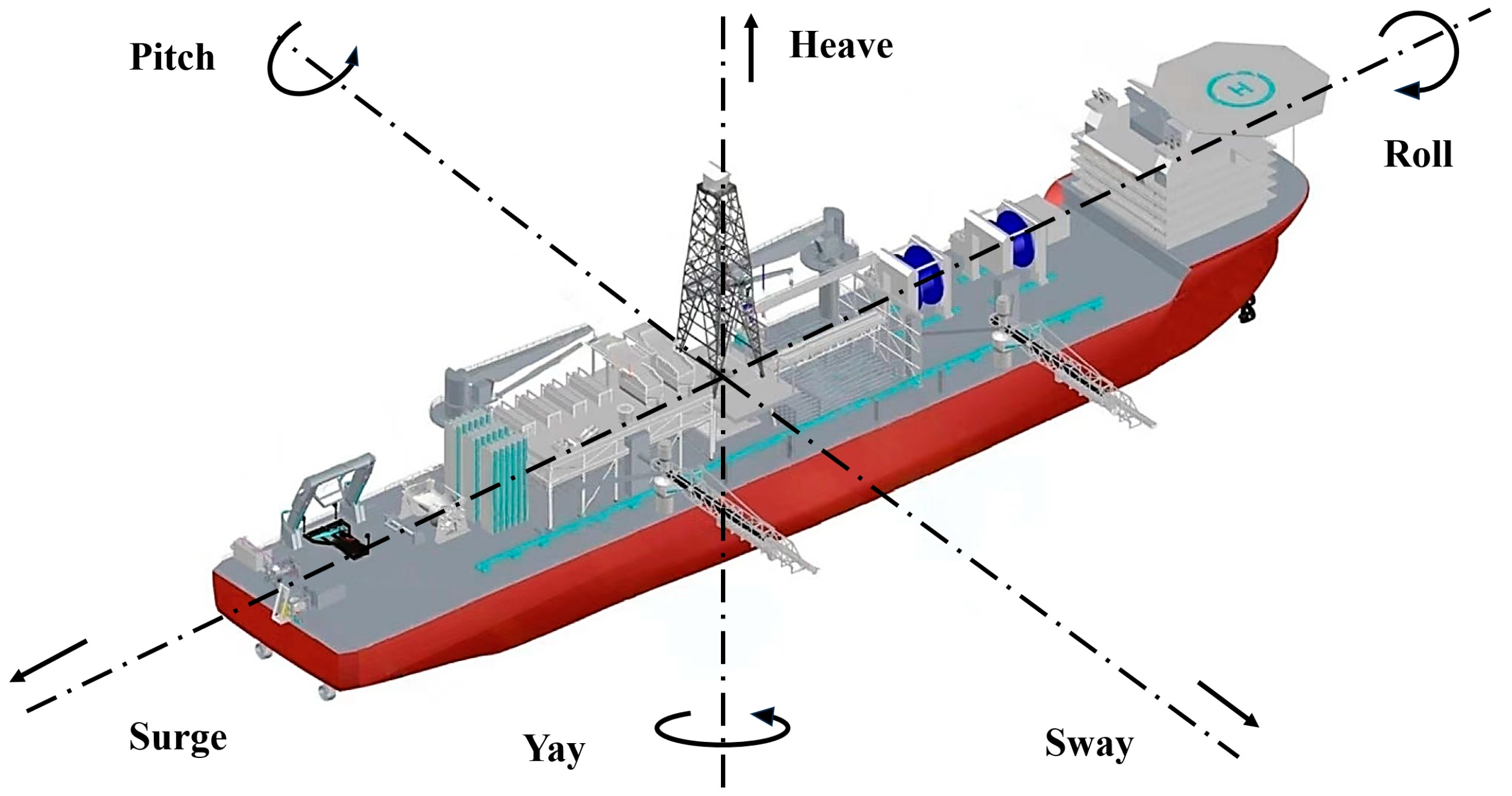
3.1. Proposal for Pitch and Roll Motion Compensation of the Lift Pipe System

Due to the structural characteristics of deep-sea mining systems, specific compensation for the pitch and roll motions of the lift pipe system is required. Current research generally assumes the use of gimbals to provide this compensation. However, gimbal-type compensation devices have a number of inherent disadvantages, such as their large size and limited compensation angles.
Since the 1990s, flexible joints with spherical capabilities have been applied in the connection between risers and floating platforms in offshore oil and gas production systems. Decades later, improvements in materials and fatigue strength have led to more widespread use of these flexible joints in ocean engineering, along with increased reliability [36]. The main functional components of this joint are four flexible elements: two primary elements, a secondary flexible element, and a housing. Each element is constructed as a sandwich of elastomer layers and spherically shaped metal reinforcements. These flexible components allow for a certain degree of angular deflection between the upper and lower pipes connected by the joint. According to the specifications of a flexible joint product currently on the market, its main performance parameters include allowing for a relative angular deflection of ±15° in all directions around the axis of the connected pipes, a tensile load capacity of 1800 tons, an outer diameter of approximately 1 m, and a weight of about 5 tons [37]. Based on design calculations, the lift pipe of a polymetallic nodule mining system operating at a depth of 6000 m with an annual output of 1.5 million tons would have a diameter of approximately 400 mm, while the lift pipe system would weigh around 1000 tons, with an underwater weight of about 500 tons with buoyancy materials attached [38]. Comparing these specifications, the aforementioned flexible joint has sufficient load-bearing capacity to suspend the lift pipe system. Its physical dimensions meet the requirements for connecting the lift pipe, and the permissible angular deflection between the upper and lower pipes can meet the pitch and roll compensation needs of deep-sea mining operations. It is, therefore, proposed to use flexible joints as pitch and roll compensation devices for mining vessels. Compared to traditional inner- and outer-ring gimbal mechanisms, these flexible joints significantly reduce the size of the structure. They can also be installed beneath the mining vessel, thereby freeing up deck space, while providing greater pitch and roll compensation angles.

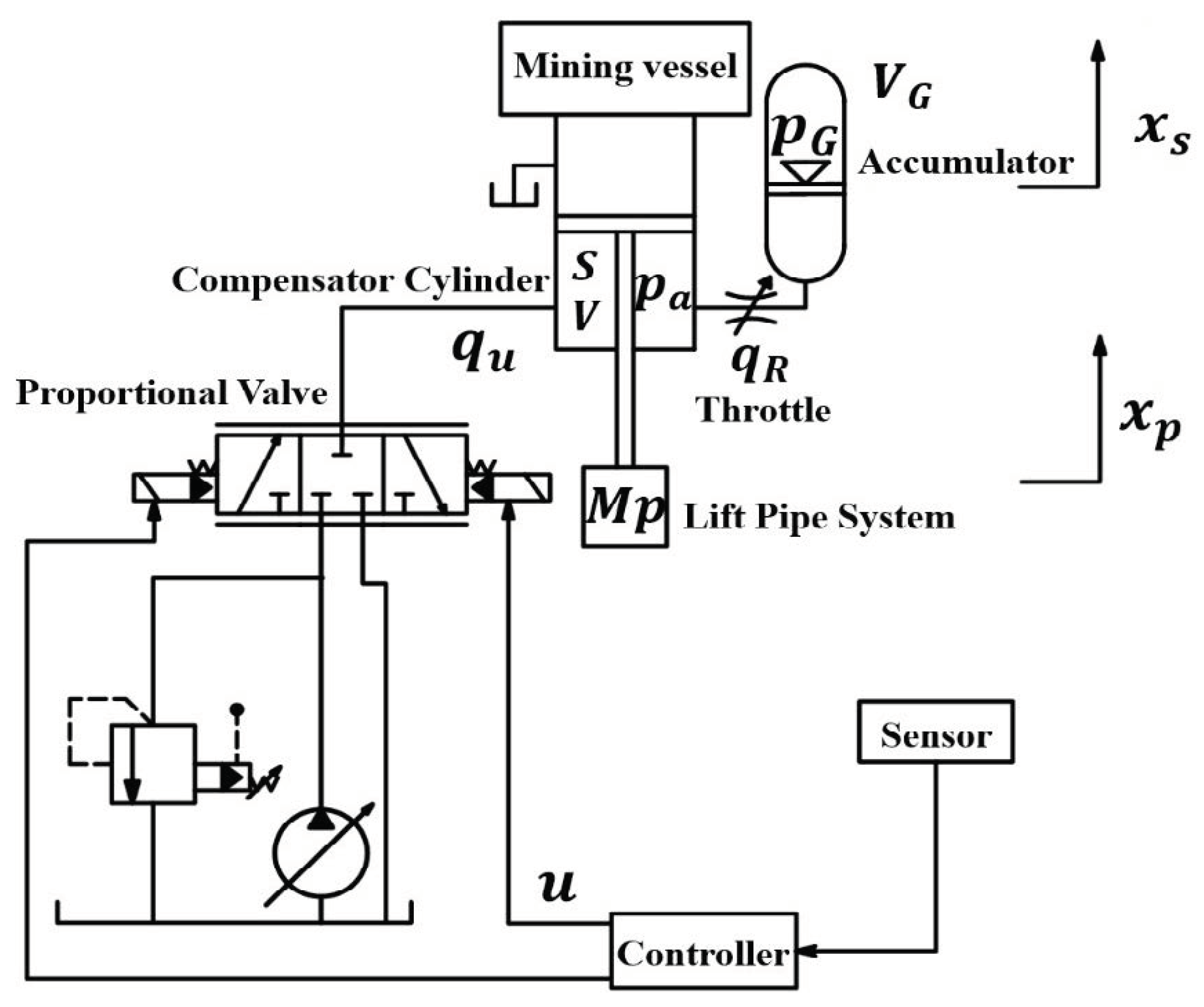
3.2. Proposal for Heave Motion Compensation and Heave Compensation System Design

In deep-sea mining systems, heave motion compensation is typically carried out by means of hydraulic (or pneumatic) cylinders, which often also handle the deployment and recovery of the lift pipe. When active heave compensation is applied, some designs control both chambers of the cylinder, while others use single-chamber control. Looking at other systems that control cables for heave compensation, since cables can only exert upward tensile forces, when the floating platform moves up under the action of waves, the isolation and compensation for the upward movement of the underwater load can only be achieved through the use of the load’s own weight. In the case of deep-sea mining systems, the load of the lift pipe system is much heavier. Therefore, when the mining vessel moves upward, the weight of the pipe system combined with the release of oil from the lower chamber of the compensation cylinder can suppress the upward movement of the lift pipe along with the mining vessel. Thus, for the hydraulic cylinders in the heave compensation system, a single-chamber control method—where only the lower chamber’s oil flow is regulated—can be used. Compared to dual-chamber control, this simplifies the hydraulic circuit and control system.
The energy consumption of active heave compensation systems is an important consideration, particularly for deep-sea mining systems, which operate under heavy loads and far from land. Due to this consideration, some studies have proposed the use of an active–passive hybrid system [39]. However, in this sort of system, pneumatic cylinders are typically used to support the underwater load. Due to the relatively low air pressure and the significant weight of the lift pipe system, the passive compensation cylinders in deep-sea mining applications would need to be quite large in size. Moreover, although passive systems theoretically do not require their own power source, in practice, equipment is still required to refill the air. Therefore, if a hybrid system is used, the mining vessel would need both pneumatic and hydraulic systems to ensure proper heave compensation, which would inevitably increase the complexity of the system and the deck space required. To address this, it is proposed that we use valve-controlled high-pressure compensation cylinders with high-pressure accumulators for heave motion compensation (see Figure 3). The charge pressure of the accumulator is based on the oil pressure required to support the static load of the lift pipe system, establishing a pressure balance point for the heave compensation system. The accumulator is connected to the lower chamber of the compensation cylinder via a controllable throttle valve. When the cylinder requires a large inflow or outflow of oil, the accumulator assists by supplying or draining oil. If the disturbance frequency is too high for the system to respond, the accumulator acts as a “gas spring”, providing passive compensation. Because the system operates at a high oil pressure, the size of the cylinder and the system as a whole can be relatively small. The accumulator’s assistance in terms of oil supply and drainage also reduces peak flow rates, thereby reducing the power and size requirements for the oil pump and motor. As a result, the entire heave motion compensation system will become more compact. In principle, the accumulator can support the lift pipe system by maintaining a closed oil circuit at the mid-point of the control valve during static loads. During operation, in addition to valve-controlled cylinder compensation, variable pumps can be used to adjust the system’s oil supply as needed, and low-pressure unloading can be executed via electronically controlled relief valves to save energy (see Figure 4).
Based on the above analysis, and considering structural factors, a heave motion compensation mechanism is proposed, consisting of two synchronized compensation cylinders with accumulators. Together with the aforementioned flexible joint, this forms the proposed structural concept for the deep-sea mining heave compensation system, as shown in Figure 3. In terms of parameter design, the system’s rated oil pressure is set to 25 MPa, a commonly used value in engineering applications. The balance point is calculated with the lift pipe system in a static state, with the cylinder’s inner diameter set to 450 mm and the piston rod diameter to 250 mm. Considering that the mining system must withstand Sea State 6 conditions and handle pipe deployment and recovery operations, the working stroke of the compensation cylinders is set to 4 m. Structurally, the volume of the accumulator is set to be equal to the volume of the compensation cylinder, in order to account for system arrangement and design considerations.

4. Research and Proposal of Heave Compensation Control Methods for Deep-Sea Mining

Modern deep-sea mining systems often recommend the use of active heave compensation, and the existing research has explored various control algorithms. These different control methods and algorithms each have their own objectives and characteristics. However, it must be considered that there are significant non-linear and uncertain factors in the heave compensation systems which are based on hydraulic or pneumatic mechanisms. In addition, these systems operate for long durations in vast and complex environments with varying sea conditions. From an engineering application perspective, control methods that do not rely on precise mathematical models for the system may be more practical. The ability to adapt to different sea conditions is also a key factor to consider. Control strategies such as proportional control, PID control, and fuzzy control do not rely on precise system models and are widely used in engineering practice. Of these, the fuzzy PID control method is particularly effective as it can adjust the PID control parameters based on the deviation between the system’s actual output and the desired output, providing strong adaptability to varying operational environments. In the following section, the performance of fuzzy PID control for deep-sea mining heave compensation is analyzed and validated through dynamic modeling and numerical simulation.

4.1. Construction of a Dynamic Model for the Proposed Heave Compensation System

In the heave compensation system shown in Figure 3, the working principle and dynamic analysis of the heave compensation are illustrated in Figure 4.
For the heave compensation system depicted in Figure 4, applying the relevant physical equations yields the following relationships:
The heave motion equation for the compensation cylinder piston rod and the lift pipe system is as follows:
M p x ¨ p = c ( x ˙ p x ˙ s ) + p a S M p g
The relationship between the liquid pressure in the rod-side chamber of the compensation cylinder and its compression is as follows:
p ˙ a = K V [ q u q R S ( x ˙ p x ˙ s ) ]
The Taylor-expanded and linearized equation of the gas state in the accumulator at the equilibrium point is as follows:
p ˙ G = n p G 0 V G 0 1 q R
The flow equation for the throttle valve, calculated and linearized according to the thin-wall orifice principle, is as follows:
q R = C d p a p G
In the above equations, M p   represents the half mass of the piston rod, the heave platform, and the lift pipe system (with buoyant materials attached and located underwater), 279 t; x p and x s   denote the vertical displacements of the piston rod and the mining vessel; S is the effective area of the piston in the rod-side chamber of the compensation cylinder, 0.1099 m2; c is the viscous damping coefficient of the compensation cylinder, 5000 N . s / m ; p a and p G are the pressure in the rod-side chamber of the compensation cylinder and the accumulator, respectively, and the initial (equilibrium) pressure is set to 25 MPa; q u and q R represent the inflow and outflow rates through the electro-hydraulic proportional valve into and out of the cylinder, and the flow rate between the cylinder and the accumulator through the throttle valve; V and V G are the volumes of the liquid inside the rod-side chamber of the compensation cylinder and the gas inside the accumulator, respectively, and its initial volume was all set to 0.1 m3; K is the bulk modulus of hydraulic oil, 1000 × 10 6   P a ; n denotes the adiabatic index of the gas, and the value here is 1; and C d is the linearized flow coefficient of the throttle orifice, and the calculation resulted in 0.025.
At the system’s equilibrium position, the pressure in the rod-side chamber in the cylinder equals the charge pressure in the accumulator, i.e., p a 0 = p G 0 = M p g .
Further definitions: p a p G = p a p a 0 p G p G 0 = Δ p a Δ p G ;
State variables: x = x ˙ p Δ p a Δ p G T ;
Control variables: u = q u ;
External disturbances: d = x ˙ s ;
Output variables: y = x ˙ p .
Thus, by combining Equations (1) through (4) and converting them into state equations, the dynamic model of the proposed heave motion compensation system can be obtained:
x ˙ = A x + B u + E d y = C x
where
A = c M p S M p 0 K S V K C d V K C d V 0 n p G 0 C d V G 0 n p G 0 C d V G 0   B = 0   K V   0 T E = c M p   K S V   0 T C = 1   0   0

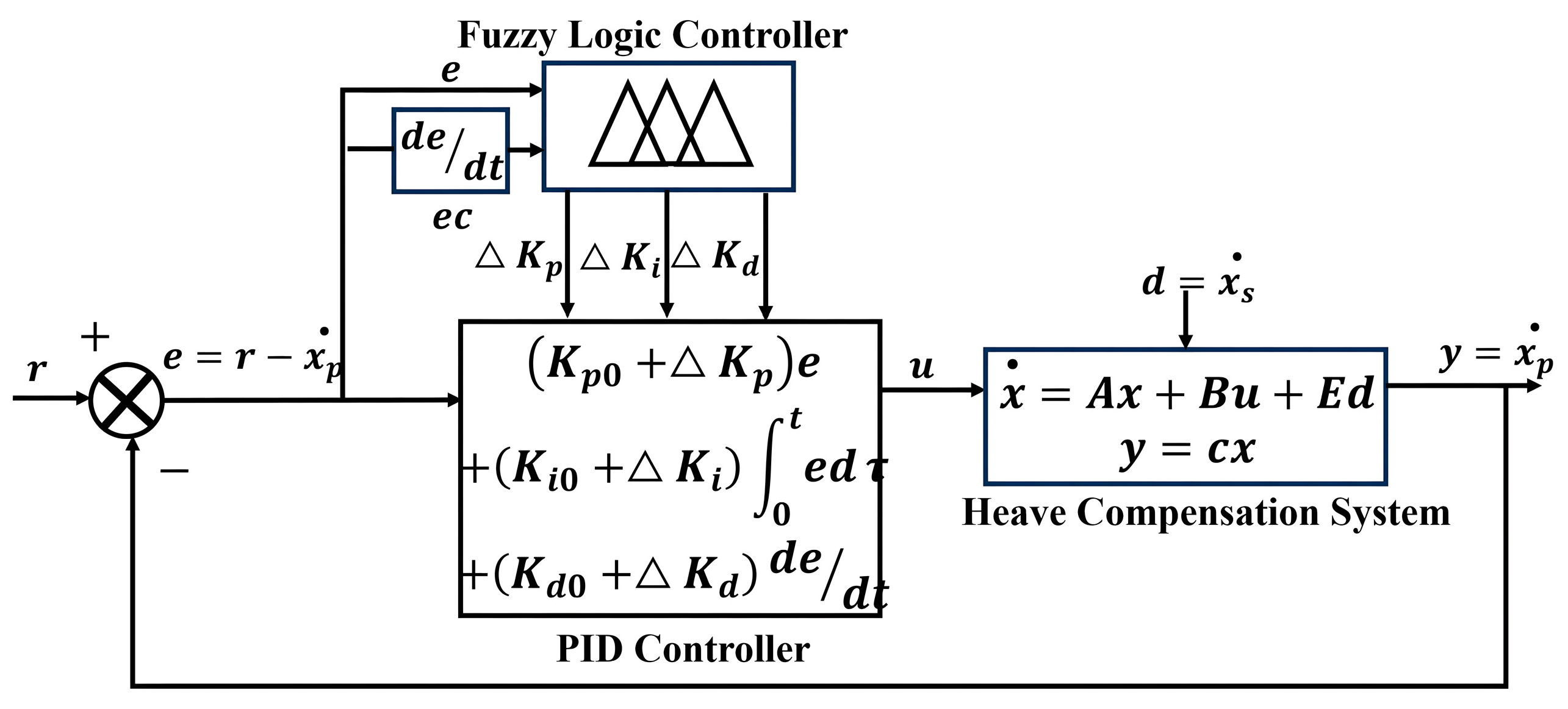
4.2. Design of the Fuzzy PID Control System for Heave Motion Compensation

Using the fuzzy PID control method, a fuzzy PID control system for heave motion compensation can be established based on the dynamic model shown in Equation (5). The structure of the control system is illustrated in Figure 5.
In Figure 5, the system output is the heave velocity of the compensation cylinder’s piston rod and the lift pipe system ( x ˙ p ), with r representing the desired system output (r = 0), and the heave motion of the mining vessel ( d = x ˙ s ) serving as the disturbance input to the system. Structurally, the fuzzy PID control system essentially includes two controllers, where the fuzzy controller performs fuzzy inference to adjust the control parameters of the PID controller. Specifically, the fuzzy controller takes the measured heave velocity of the piston rod ( e = − x ˙ p ) and its derivative ( e c = x ¨ p ) as inputs. Based on the designed membership functions and fuzzy inference rules, the fuzzy controller calculates the recommended increments ( Δ K p , Δ K i , and Δ K d ) for the three PID control parameters in real time. The PID controller then uses the initial control parameters ( K p 0 , K i 0 , and K d 0 ) and the control parameter increments provided by the fuzzy controller to compute the control flow ( u = q u ) to the compensation cylinder based on the PID control law. This enables the system to compensate for the heave motion of the lift pipe system caused by the disturbance from the mining vessel’s heave motion ( d = x ˙ s ), aiming to minimize the error ( e = r x ˙ p ) between the system’s actual output and the desired output.
A simulation platform for the control system, as illustrated in Figure 5, was developed using MATLAB (R2021b) and SIMULINK (R2021b). The PID controller module was constructed using the PID Controller block in SIMULINK, while the fuzzy controller was designed and implemented via MATLAB’s Fuzzy Logic Toolbox. Both controllers were integrated with the control system model in the SIMULINK environment to establish a simulation platform for analyzing the performance of a fuzzy PID control system for heave motion compensation. The fuzzy logic inference system features two inputs ( e = − x ˙ p and e c = x ¨ p ) and three outputs ( Δ K p , Δ K i , and Δ K d ), corresponding to the proportional, integral, and derivative terms of PID control. Fuzzy inference rules were formulated based on the magnitude of the inputs. For instance, larger values of e and ec result in a higher Δ K p to enhance compensation force, whereas smaller inputs yield a reduced Δ K d to avoid overshoot. The inference system comprises three rule tables, each containing 49 rules. Although these expert experience-based rules provide reasonable parameter adjustment directions, the optimization of the output parameters was further achieved by introducing tuning factors for each parameter. These factors were iteratively determined through extensive simulation trials. Consequently, the actual incremental control parameters ( Δ K p , Δ K i , and Δ K d ) fed into the PID controller are calculated as the product of the fuzzy controller outputs and their corresponding tuning factors.

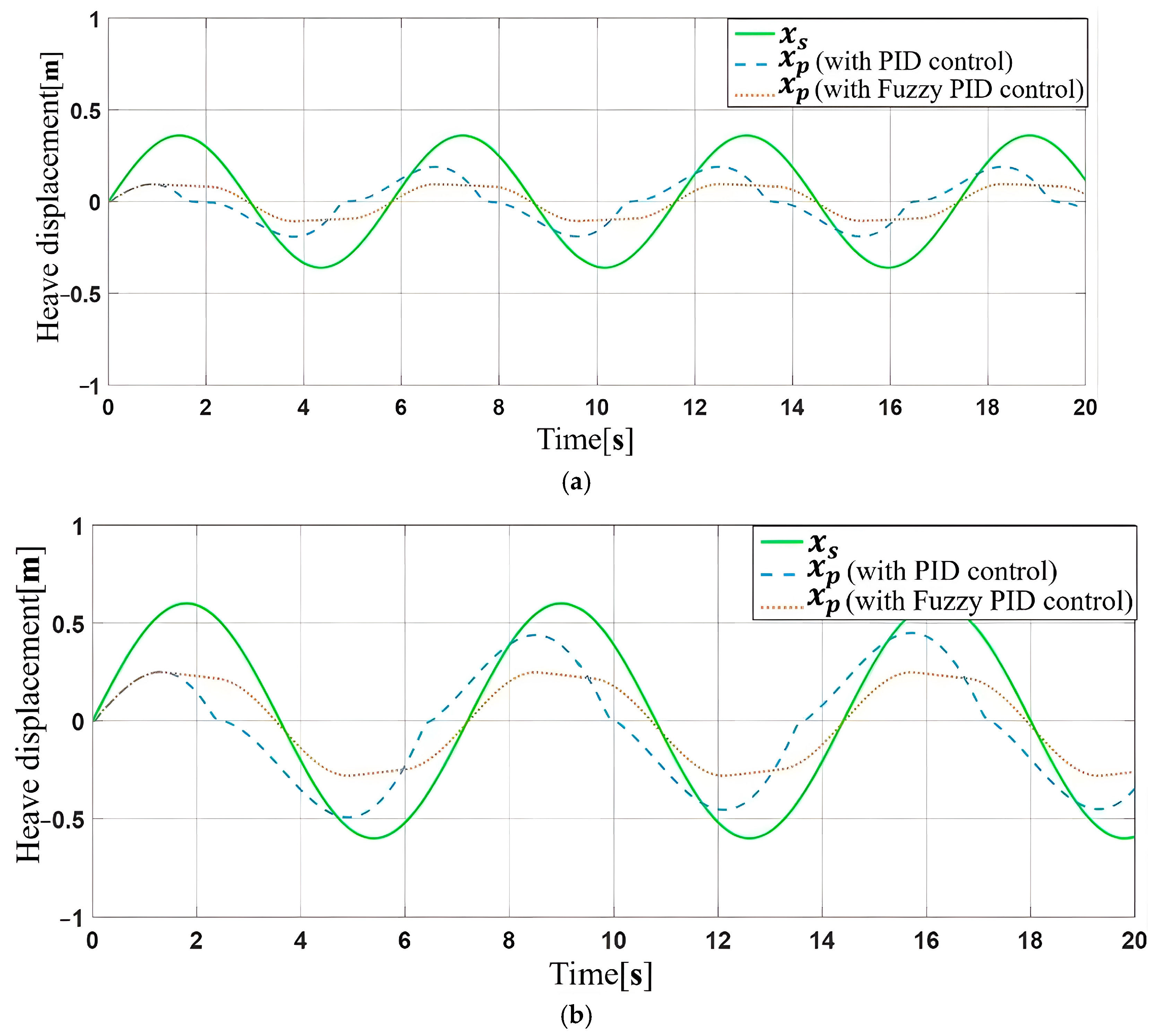
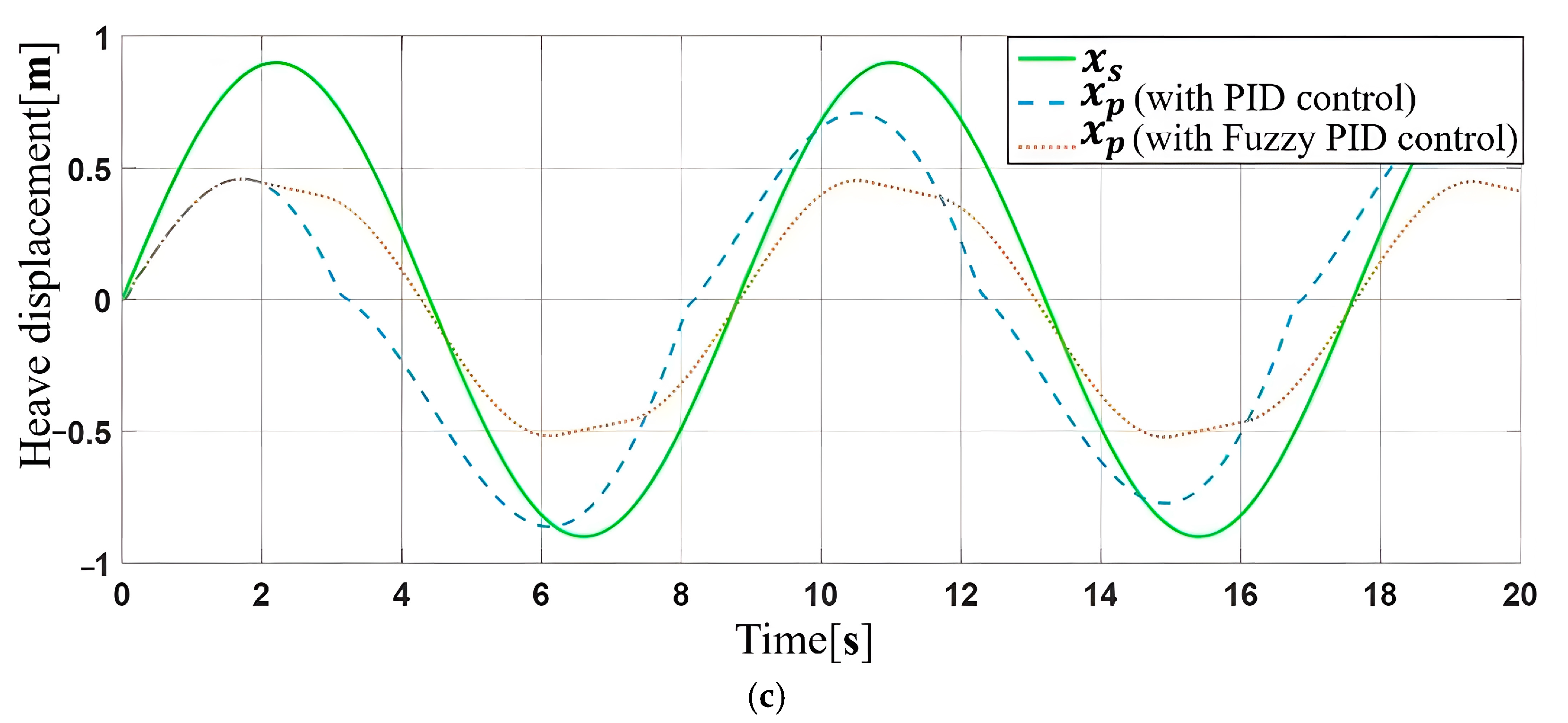
4.3. Analysis of Heave Motion Compensation Performance Based on Fuzzy PID Control

Assume that the heave motion of the mining vessel, caused by wave action, follows a sinusoidal wave. Based on the amplitudes and periods listed in Table 1, disturbance signals are generated to simulate the vessel’s heave motion in Sea States 4 to 6. Numerical simulations are then performed to analyze the control performance of the heave motion compensation system under these different sea state disturbance signals.
First, an analysis of the conventional PID control performance for heave compensation is conducted with the fuzzy controller disabled. Using the PID Tuner in SIMULINK, the control parameters for the conventional PID controller are optimized for the best balance of response speed (0.235 s) and overshoot (8.13%). The optimized initial PID control parameters are set as follows:
Proportional gain K p 0 = 8 ;
Integral gain K i 0 = 1 ;
Derivative gain K d 0 = 0.1 .
These parameters are then input into the system for simulation. The resulting heave motion curves of the lift pipe system under different sea state conditions with PID control are shown in Figure 6.
Next, the fuzzy controller is activated. Based on the deviation e as well as the rate of change e c , the fuzzy inference system calculates the increments for the PID control parameters, adjusting the control strength of the PID controller accordingly.
A further analysis of the variation trends and patterns of the control parameter increments during the simulation reveals the following:
  • The amplitude of changes in Δ K p is much larger than that of Δ K i and Δ K d , indicating that the fuzzy PID controller primarily adjusts the proportional control parameter to alter the controller’s output signal;
  • In the same sea state, Δ K p increases linearly with the heave velocity of the lift pipe system, with a generally consistent trend, but, when the heave velocity approaches zero, it takes a smaller value within a certain range and remains relatively constant;
  • Under different sea conditions, Δ K p increases more significantly in higher sea states.
Overall, unlike conventional PID control where the parameters remain unchanged, in the fuzzy PID control law developed in this study, the proportional control coefficient ( K p 0 + Δ K p ) takes a larger value as the mining vessel’s heave velocity increases, resulting in a greater control output.
The heave motion curves for the lift pipe system under different sea conditions using fuzzy PID control are also shown in Figure 6.
If the compensation rate is defined as η = 1 A x p / A x s (where A x s represents the maximum displacement in the heave direction of the mining vessel, and A x p represents the maximum displacement of the lift pipe system in the heave direction), the heave motion compensation rates for the system under different sea conditions using both PID control and fuzzy PID control can be obtained, as shown in Table 2:
In the table, η ( 6 ) and η ( 4 ) represent the heave motion compensation rates of the system under Sea State 6 and Sea State 4, respectively.
From Figure 6 and Table 2, it is evident that, compared to conventional PID control, fuzzy PID control achieves better heave compensation rates. The compensation improvement rate of fuzzy PID control ranges from 26.4% to 33.62% as sea states increase from level 4 to level 6, with higher sea states showing greater improvement. Fuzzy PID control also demonstrates better adaptability under varying sea conditions. Using conventional PID control, the system’s heave compensation rate at Sea State 6 is only 36% of that at Sea State 4, whereas, with fuzzy PID control, the compensation rate at Sea State 6 reaches 69% of that at Sea State 4. These results indicate that, compared to the conventional fixed-parameter PID control, the fuzzy PID control method can dynamically adjust the control parameters based on the heave velocity and acceleration of the lift system, leading to better compensation rates and more effective heave compensation under varying wave heights and periods. Therefore, it is recommended that the proposed heave compensation system utilize fuzzy PID control.

5. Conclusions

(1)
The characteristics of heave compensation for deep-sea mining were analyzed in this paper. Since the underwater load is a multi-kilometer-long lift pipe system suspended beneath the mining vessel, heave compensation for deep-sea mining is not typically performed by controlling cables. Instead, it is generally executed using long-stroke hydraulic (or pneumatic) cylinders, and a specialized mechanism is required for compensating pitch and roll motions.
(2)
A heave compensation system for deep-sea mining is proposed. This system replaces traditional gimbal mechanisms with flexible joints to compensate for pitch and roll motions, increasing the compensation angles from less than ±10° to ±15° without occupying the deck area of the mining vessel. A single-chamber, valve-controlled compensation cylinder with a high-pressure accumulator is employed for heave motion compensation. This configuration is compact and capable of generating a large compensation force. The flexible joint and high-pressure hydraulic control system have been successfully implemented in the offshore oil and gas industry, demonstrating strong economic viability and engineering feasibility. The proposed solutions have completed conceptual design and obtained Approval in Principle (AIP) certification from the China Classification Society.
(3)
The fuzzy PID control method for the heave compensation system in deep-sea mining and its application effects are studied. Using commercial deep-sea polymetallic nodule mining operations as the research background, a dynamic model is established for the proposed heave motion compensation system, and the control system is designed based on the fuzzy PID control method. Subsequently, an analysis of heave compensation performance under different sea conditions is conducted. The results indicate that the fuzzy PID control system dynamically adjusts the PID controller parameters, particularly the proportional control gain, according to the heave velocity and acceleration of the lifting pipeline: when the heave velocity and acceleration are high, a larger proportional gain is applied to enhance compensation; when they are low, a smaller gain is used to conserve compensatory energy. Therefore, compared to conventional PID control, fuzzy PID control achieves a superior heave compensation performance under disturbances of varying magnitudes and frequencies, improving the mining system’s capability to compensate for heave motion across diverse sea conditions.

Author Contributions

Conceptualization, S.L.; data curation, C.W.; formal analysis, C.W.; funding acquisition, Y.K.; investigation, Y.K. and H.F.; methodology, Y.K. and S.L.; software, H.F. and C.W.; validation, Y.K. and H.F.; visualization, C.W.; writing—original draft, Y.K.; writing—review and editing, H.F. and S.L. All authors have read and agreed to the published version of the manuscript.

Funding

This research was funded by the National Natural Science Foundation of China, grant number 52201314.

Data Availability Statement

The original contributions presented in this study are included in the article. Further inquiries can be directed to the corresponding author.

Conflicts of Interest

The authors declare no conflicts of interest.

References

  1. Zinage, S.; Somayajula, A. A comparative study of different active heave compensation approaches. Ocean Syst. Eng. 2020, 10, 373–397. [Google Scholar] [CrossRef]
  2. Xie, T.C.; Huang, L.P.; Zou, D.S.; Chen, L.; Liu, D.S. Modelling and simulation analysis of active heave compensation control system for marine winch. Ocean Eng. 2021, 39, 1005–1009. [Google Scholar] [CrossRef]
  3. Yan, F.; Fan, K.; Yan, X.C.; Li, S.Z. Constant tension control of hybrid Active-Passive heave compensator based on adaptive integral sliding mode method. IEEE Access 2020, 8, 103782–103791. [Google Scholar] [CrossRef]
  4. Luo, M.Y. Research on Control System of ROV Active Heave Compensation Based on Prediction of Motion. Ph.D. Thesis, Shanghai Jiao Tong University, Shanghai, China, 2020. [Google Scholar]
  5. Ni, J.; Liu, S.; Wang, M.; Hu, X.; Dai, Y. The simulation research on passive heave compensation system for deep sea mining. In Proceedings of the International Conference on Mechatronics and Automation, Changchun, China, 9–12 August 2009; pp. 5111–5116. [Google Scholar] [CrossRef]
  6. Hatleskog, J.T.; Dunnigan, M.W. Heave compensation simulation for non-contact operations in deep water. In Proceedings of the OCEANS 2006, Boston, MA, USA, 18–21 September 2006; pp. 1–6. [Google Scholar] [CrossRef]
  7. Korde, U.A. Active heave compensation on drill-ships in irregular waves. Ocean Eng. 1998, 25, 541–561. [Google Scholar] [CrossRef]
  8. Woodacre, J.K.; Bauer, R.J.; Irani, R.A. A review of vertical motion heave compensation systems. Ocean Eng. 2015, 104, 140–154. [Google Scholar] [CrossRef]
  9. Hu, Z.W.; Song, Y. Experiment Research on the Power Characteristics of Heavy-Duty Semi-Active Heave Compensation Hydraulic System. Chin. Hydraul. Pneum. 2020, 5, 80–85. [Google Scholar]
  10. Teng, Y.Y.; Hu, Z.G.; Song, Y.; Chen, L.K. Energy Consumption Analysis of Mining Ship Heave Compensation System Based on AMESim. Mach. Tool Hydraul. 2023, 11, 170–174. [Google Scholar] [CrossRef]
  11. Kuchler, S.; Mahl, T.; Neupert, J.; Schneider, K.; Sawodny, O. Active control for an offshore crane using prediction of the vessels motion. IEEE/ASME Trans. Mechatron. 2011, 16, 297–309. [Google Scholar] [CrossRef]
  12. Hatleskog, J.T.; Dunnigan, M.W. Active heave crown compensation subsystem. In Proceedings of the OCEANS 2007—Europe, Aberdeen, UK, 18–21 June 2007; pp. 1–6. [Google Scholar] [CrossRef]
  13. Chen, H.; Wang, X.; Benbouzid, M.; Charpentier, J.-F.; Aϊt-Ahmed, N.; Han, J. Improved Fractional-Order PID Controller of a PMSM-Based Wave Compensation System for Offshore Ship Cranes. J. Mar. Sci. Eng. 2022, 10, 1238. [Google Scholar] [CrossRef]
  14. Kang, Y.J.; Liu, S.J. The development history and latest progress of Deep-Sea polymetallic nodule mining technology. Minerals 2021, 11, 1132. [Google Scholar] [CrossRef]
  15. Wang, M.H.; Jian, Q. Study on mining environment in China’s ocean mining area. China Min. Mag. 1996, 4, 22–25. [Google Scholar]
  16. Kang, D.; Kang, H.; Lee, K.; Ryu, M.; Lee, S.; Park, S. The preliminary front-end engineering and design of manganese nodules mining vessel. In Proceedings of the OCEANS—Yeosu, Yeosu, Republic of Korea, 21–24 May 2012; pp. 1–8. [Google Scholar] [CrossRef]
  17. Hu, Q. The Simulation Test Research on Mechanical Behavior of the Lifting Pipe System of Deep-Ocean Mining. Ph.D. Thesis, Central South University, Changsha, China, 2011. [Google Scholar]
  18. Li, L.J. Study on Design and Control of Active Heave Compensation System of Deep-Sea Mining Based on Dynamic Vibration Absorber. Ph.D. Thesis, Central South University, Changsha, China, 2012. [Google Scholar]
  19. Zheng, X.Z. Research on Kinematics of Hybrid Serial-Parallel Mechanisms for Compensating Platform in Deep-Ocean Mining. Ph.D. Thesis, Huazhong University of Science and Technology, Wuhan, China, 2004. [Google Scholar]
  20. Mcnary, J.F.; Person, A.; Ozudogru, Y.H. A 7500 ton capacity shipboard completely gimbaled and heave compensated platform. J. Pet. Technol. 1977, 29, 439–448. [Google Scholar] [CrossRef]
  21. Kaufman, R.; Latimer, J.P.; Tolefson, D.C.; Senni, S. The design and operation of a pacific ocean Deep-Ocean mining test ship: R/V Deepsea Minner 2. In Proceedings of the Offshore Technology Conference, Houston, TX, USA, 6–9 May 1985. OTC-4901-MS. [Google Scholar] [CrossRef]
  22. Brockett, F.H.; Huizingh, J.P.; McFarlane, J.A.R. Updated analysis of the capital and operating costs of a polymetallic nodule deep ocean mining system developed in the 1970s. In Proceedings of the ISA Workshop on Polymetallic Nodule Mining Technology, Chennai, India, 18–22 February 2008; pp. 54–80. [Google Scholar]
  23. Xiao, T.B.; Wu, B.H.; Luo, Z.H. Research on design and simulation of active heave compensation system of heavy lifting mine pipeline. Mach. Tool Hydraul. 2002, 6, 47–51. [Google Scholar]
  24. Tang, X.; Liu, S.; Huang, K. Design and simulation study on a virtual prototype of an active heave compensation system for Deep-ocean mining. In Proceedings of the Sixth ISOPE Ocean Mining Symposium, Changsha, China, 9–13 October 2005. [Google Scholar]
  25. Xiao, S.Y.; Xiao, T.B.; Liao, H.; Wu, B.H. Design and simulation of Heavy-load 3-Dimension motion compensation system for Deep-sea mining device. Mach. Tool Hydraul. 2009, 37, 202–204. [Google Scholar]
  26. Guo, Z.X. Study on Coupled Motion and Heave Compensation of Hydraulic Lifting System for Deep Sea Nodules. Ph.D. Thesis, Harbin Engineering University, Harbin, China, 2023. [Google Scholar]
  27. Zeng, F.Y. Design and Simulation Study of the Heave Compensation System Combined Action of Vibration Absorber and Accumulator. Ph.D. Thesis, Central South University, Changsha, China, 2010. [Google Scholar]
  28. Li, L.; Liu, S. Modeling and simulation of active-controlled heave compensation system of deep-sea mining based on dynamic vibration absorber. In Proceedings of the International Conference on Mechatronics and Automation, Changchun, China, 9–12 August 2009; pp. 1337–1341. [Google Scholar] [CrossRef]
  29. Lu, C. Research on Control Methods and Modeling and Simulation for the Wave Compensation System in the Deep-Sea Mining. Ph.D. Thesis, Wuhan University of Technology, Wuhan, China, 2009. [Google Scholar]
  30. Xiao, Q.J.; Wu, B.H.; Xiao, T.B.; Luo, Z.H. Fuzzy hybrid PID control applied in the deep sea mining heave compensate simulation system. Chin. Hydraul. Pneum. 2004, 10, 49–51. [Google Scholar]
  31. Li, W.H. Research on Neural Network Parameters Adaptive Control for Deep-Sea Mining Heave Motion Compensation. Ph.D. Thesis, Guangdong University of Technology, Guangzhou, China, 2011. [Google Scholar]
  32. Zhang, Y.; Sun, Y.G.; Hu, Z.G.; Fang, B.F.; Xie, Y.; Chen, L.K.; Teng, Y.Y. Control performance analysis of mining ship heave compensation system based on fuzzy logic algorithm. J. Eur. Syst. Autom. 2022, 55, 213–220. [Google Scholar] [CrossRef]
  33. Teng, Y.Y.; Hu, Z.G.; Sun, Y.G. Virtual prototype modeling and fuzzy control of the heave compensation system for a 500-ton deep-sea mining vessel. Trans. Inst. Meas. Control 2024, 1–13. [Google Scholar] [CrossRef]
  34. Butler, B. Heave compensation. In Proceedings of the Second Annual European Meeting of the Society of Petroleum Engineers, London, UK, 2–3 April 1973. [Google Scholar] [CrossRef]
  35. Southerland, A. Mechanical systems for ocean engineering. Naval Eng. J. 1970, 82, 63–74. [Google Scholar] [CrossRef]
  36. Groves, S.; Hogan, M.; Moses, S.A.; Dean, R.; Hartley, F.T. Flexible joint improvements may aid reliability. Offshore 2006, 66, 88–90. [Google Scholar]
  37. Oil States Industries, Inc. Technical Manual for Diverter II Flexible Joint Assembly; Oil States Industries: Arlington, TX, USA, 2015. [Google Scholar]
  38. Alex, R.; Li, J.; Liu, T.J. A riser and lifting system concept for deep sea polymetallic nodule mining. In Proceedings of the 50th Underwater Minerals Conference, St. Petersburg, FL, USA, 2–7 October 2022; pp. 1–12. [Google Scholar]
  39. Xiao, T.B. Research on Intelligent Heave Compensation System for Deep-Sea Mining Device. Ph.D. Thesis, Guangdong University of Technology, Guangzhou, China, 2004. [Google Scholar]
Figure 1. The six degrees motion of surface vessels induced by wind and waves.
Jmse 13 00652 g001
Figure 2. Schematic diagram of the pipe-lift deep-sea mining system.
Jmse 13 00652 g002
Figure 3. Proposed deep-sea mining heave compensation system. 1. System Platform; 2,10. Accumulator; 3,9. Controllable Throttle Valve; 4,8. Compensation Cylinder; 5. Heave Platform; 6. Flexible Joint; 7. Lift Pipe.
Jmse 13 00652 g003
Figure 4. Dynamic analysis of heave compensation system.
Jmse 13 00652 g004
Figure 5. Structure diagram of the heave motion compensation fuzzy PID control system.
Jmse 13 00652 g005
Figure 6. Heave motion curves using PID control and fuzzy PID control under different sea conditions: (a) heave motion curves under Sea State 4 condition; (b) heave motion curves under Sea State 5 condition; and (c) heave motion curves under Sea State 6 condition.
Jmse 13 00652 g006aJmse 13 00652 g006b
Table 1. Motion response parameters of the mining vessel under Sea States 4–6.
Sea State456
Heave Amplitude & Period0.36 m, 5.8 s0.6 m, 7.2 s0.9 m, 8.8 s
Pitch Amplitude±4°±8°±15°
Roll Amplitude±4°±15°±22°
Table 2. Heave motion compensation rates for PID control and fuzzy PID control under different sea conditions.
Sea StatePID ControlFuzzy
PID Control
Compensation Improvement Rate
447.72%74.12%26.4%
525.75%58.93%33.18%
617.16%50.78%33.62%
η ( 6 ) / η ( 4 ) 36%69%
Disclaimer/Publisher’s Note: The statements, opinions and data contained in all publications are solely those of the individual author(s) and contributor(s) and not of MDPI and/or the editor(s). MDPI and/or the editor(s) disclaim responsibility for any injury to people or property resulting from any ideas, methods, instructions or products referred to in the content.

