Article

Free- and Forced-Vibration Characteristic Analysis of a Double-Layered Cylindrical Shell with General Boundary Conditions

1
National Key Laboratory on Ship Vibration & Noise, China Ship Scientific Research Center, Wuxi 214082, China
2
Department of Physics, Wuxi University, Wuxi 214126, China
*
Author to whom correspondence should be addressed.
J. Mar. Sci. Eng. 2025, 13(4), 641; https://doi.org/10.3390/jmse13040641
Submission received: 17 February 2025 / Revised: 12 March 2025 / Accepted: 18 March 2025 / Published: 24 March 2025
(This article belongs to the Section Ocean Engineering)

Abstract

:
The double-layered cylindrical shell represents a key structural configuration for underwater vehicles, where its vibration behavior remains a primary concern in engineering design and analysis. This study develops a spectral element method (SEM) for dynamic modeling of multi-component shell systems by extending the vibrational governing equations of conical shells. The methodology is validated through finite element method (FEM) case studies on both conical shells and double-layered cylindrical configurations. Parametric investigations examine ribbed substructures and solid rib plates within the cylindrical shell assembly, while artificial spring techniques model arbitrary boundary conditions—with validation against classical benchmarks confirming their effectiveness for elastic constraints. Numerical demonstrations reveal the following: rib and plate thickness variations exhibit a negligible impact on low-frequency vibrational responses; the natural frequency sensitivity peaks when the elastic boundary stiffness approaches the inherent dynamic stiffness of the shell’s base configuration, while extreme stiffness values approximate clamped or free boundary conditions with engineering significance. The proposed SEM framework demonstrates a superior computational efficiency and accuracy compared to conventional FEM approaches. These findings deliver practical guidance for marine structural engineering, particularly in the boundary condition specifications and performance optimization of composite shell systems.

1. Introduction

The double-layered cylindrical shell is one of the common structural forms used in submarines, and its dynamic characteristics differ significantly from those of conventional single-layered ribbed cylindrical shells. Conical shell structures serve as typical stern configurations in aircraft, missiles, torpedoes, submarines, and other underwater vehicles. During flight or navigation, these structures are subjected to external excitations such as turbulence in fluid media and engine vibrations. When the frequency of external excitation loads matches or approaches the natural frequency of the conical shell structure, resonance in the stern conical shell can easily occur. Resonance amplifies vibrations in the shell itself, and prolonged excessive vibrational displacements may lead to fatigue failure of the conical shell structure, resulting in equipment malfunctions and potential catastrophic consequences. Therefore, dynamic modeling and computational analysis of a double-layered cylindrical shell are required to ensure a reliable design.
Over the last few decades, extensive works have been carried out by researchers to investigate the vibration characteristics of cylindrical shell and combined structures [1,2,3,4,5,6,7,8,9,10,11]. The dynamic stiffness method (DSM) is one of the common methods for vibration analysis of cylindrical shells [12,13]. Zhu [14] developed a dynamic stiffness method for the vibration analysis of laminated cylindrical and conical shells, which are partially filled or surrounded by quiescent fluid. Zhang [15,16] also used the DSM to investigate the vibration characteristics of conical shell and ribbed cylindrical–conical shell coupled structures, where both an experimental model and FEM were used to verify the accuracy and stability of the DSM. Based on the above research, Li [17,18] extended the dynamic stiffness method to open cylindrical shells, which can allow for considering the internal elements of submarine structures, such as equipment bases.
Chen and Xie [19,20] presented an analytical method to analyze free and forced vibration characteristics of ring-stiffened combined conical–cylindrical shells with arbitrary boundary conditions. Tian [21] extended the DSM to analyze the free and forced vibration of combined conical–cylindrical shells, and when comparing their results with the open-access literature, the rapid convergence, good accuracy, and high efficiency of the DSM were demonstrated. In addition, the authors developed a hybrid analytic–numerical formulation to study the vibration behaviors of a cylindrical shell coupled with an internal flexural floor structure [22]. Similar to the DSM, Wu [23,24] used the impedance synthesis method (ISM) to establish a laminated conical–cylindrical coupling structure, and they coupled the liquid-filling pipeline system inside the submarine with the composite shell for modeling and analysis.
However, there is still relatively little literature on the vibration of double-layered cylindrical shells. Wang [25] combined the traditional transfer matrix method and precise integration method and analyzed vibro-acoustic behavior of submerged double-walled cylindrical shells with general boundary conditions. Yu [26] investigated the vibration transmission characteristics of a double-layered cylindrical shell with fully immersed elastic connections. Xie [27,28] developed a novel semi-analytic model for the vibro-acoustic analysis of immersed double-walled cylindrical shells coupled with annular plates, and the effects of locations, thicknesses, and the number of annular plates were studied. Furthermore, the combined double-layered cylindrical shells’ interior annular fluid region and exterior infinite fluid region were separately analyzed with the Helmholtz surface integral equation [29]. Based on Flügge shell theory and the wave-based method (WBM), Jia [30] proposed a unified semi-analytical method of double-walled cylindrical shells with arbitrary connections. Based on the principle of energy and the Rayleigh–Ritz method, Zhang [31] established a laminated composite double cylindrical shell coupled with several annular plates. Yoshikawa [32] established a coupling model of infinite double-layered cylindrical shells under point excitation based on the Fourier transform method in the wavenumber domain.
This paper proposes a dynamic model prediction method for complex combined shell structures based on conical shells, which is tested through a comparative analysis with examples. The method for calculating the natural frequency of conical shells proposed in the present article is based on theoretical analysis, which has the advantages of a fast calculation speed and high convergence. In addition, only a few parameters, such as the geometric dimensions and material of the conical shell, need to be input during the calculation process. In contrast, the existing commercial finite element software requires remodeling and meshing for conical shells of different geometric sizes, with a significant associated time and cost. The parameter modeling analysis in the present article has significant advantages. This approach enables engineers in the aerospace, aviation, and shipbuilding industries to rapidly evaluate the natural frequency of a conical shell and other stern structures during the design stage. Based on the evaluation results, geometric parameters of the conical shell can be optimized to prevent resonance between its natural frequency and external excitation frequencies, thereby enhancing the safety and reliability of equipment incorporating conical shell structures.

2. Theoretical Model

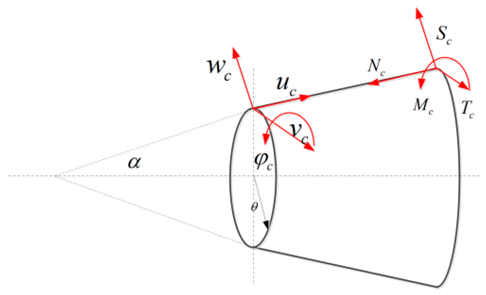
2.1. Vibration Equation of Conical Shell

Starting from the displacement vibration governing equations of conical shells, this paper expresses the displacement responses in three directions in power series form. Through convergence analysis of the power series, the truncation number m for the power series in the displacement expressions and the circumferential modal truncation number n are determined. According to classical thin shell theory [9], the vibration governing equations for conical shells are
L 11 c u c + L 12 c v c + L 13 c w c = 0 L 21 c u c + L 22 c v c + L 23 c w c = 0 L 31 c u c + L 32 c v c + L 33 c w c = 0
In the above equations, u c , v c , and w c represent the axial, tangential, and radial displacements of the conical shell, respectively. A schematic diagram illustrating the force and displacement variables in the conical shell is shown in Figure 1. Each cross-section includes four displacement variables u c , v c , w c , φ c and four force variables N c , T c , S c , M c , where α denotes the semi-vertex angle of the conical shell.
In Equation (1), L 11 c , L 12 c , L 13 c , L 21 c , L 22 c , L 23 c , L 31 c , L 32 c , and L 33 c are the partial differential coefficients in the vibration control equation of the conical shell, respectively, which can be written as
L 11 c = s 2 R 2 + s R x + x 2 + 1 + k c 2 R 2 1 μ 2 R 2 2 θ 2 k c 2 s 2 R 4 ρ h 2 t 2 L 12 c = 1 + μ 2 R 2 x θ 3 μ 2 s R 2 θ L 13 c = μ c R x s c R 2 k c R s c 2 R 3 + s 2 R 2 x + 3 x 3 1 μ 2 R 2 3 x θ 2 + 3 μ s 2 R 3 2 θ 2 L 21 c = 3 μ 2 s R 2 θ + 1 + μ 2 R 2 θ x L 22 c = 1 R 2 2 θ 2 + 1 μ 2 s R x + x 2 s 2 R 2 + k c 2 1 μ R 2 3 s 2 2 R 2 s R x + 3 2 x 2 ρ h 2 t 2 L 23 c = c R 2 θ k c R 2 1 μ s 2 R 2 θ 3 1 μ s 2 R 2 θ x + 3 μ 2 3 θ x 2 L 31 c = s c R 2 μ c R x k c R 2 s 2 R 3 s 2 R 2 x + s c 2 R 3 3 x 3 + s 1 + μ 2 R 3 2 θ 2 + 1 + μ 2 R 2 3 x θ 2 L 32 c = c R 2 θ k c 2 R 2 s 3 + μ R 2 θ x s 2 3 + μ R 2 θ 3 μ 3 x 2 θ L 33 c = c 2 R 2 k 4 k c 2 R 4 2 + c 2 + 2 2 θ 2 ρ h 2 t 2
where s = sin α , c = cos α , k = h 2 / 12 , 4 = 2 2 , and 2 = 2 x 2 + s R x + 1 R 2 2 θ 2 . μ is Poisson’s ratio, θ is the circumferential angle, R is the radius of the conical shell, ρ is the density, and h is the thickness of the conical shell. This article uses the power series superposition method to solve this, and thus the displacement expression of the conical shell can be written as
u c x c , θ = n = 0 U n , c x c cos n θ = n = 0 m = 0 a m x c m cos n θ v c x c , θ = n = 0 V n , c x c sin n θ = n = 0 m = 0 b m x c m sin n θ w c x c , θ = n = 0 W n , c x c cos n θ = n = 0 m = 0 c m x c m cos n θ
Here, n is the circumferential mode number, m is the truncation order of the power series, x c is the displacement along the direction of the generatrix of the conical shell, θ is the circumferential angle at the position of the generatrix of the conical shell, U n , c , V n , c , and W n , c are the amplitudes of the displacement expression for the conical shell, and a m , b m , and c m are the superposition coefficients of a power series. By substituting Equation (3) into the vibration Equation (1) of a conical shell, the recursive relationship expression between the power series coefficients can be obtained:
a m + 2 = i = 1 6 A a , i a m 5 + i + i = 1 4 B a , i b m 3 + i + i = 1 4 C a , i a m 3 + i b m + 2 = i = 1 4 A b , i a m 3 + i + i = 1 6 B b , i b m 5 + i + i = 1 5 C b , i a m 3 + i a m + 2 = i = 1 6 A c , i a m 3 + i + i = 1 5 B c , i b m 3 + i + i = 1 8 C c , i a m 5 + i
In the above equation, the specific expressions of the recursive coefficients am, bm, and cm can be found in the literature [14]. Coefficients Aa,i, Ab,i, Ac,i, Ba,i, Bb,i, Bc,i, Ca,i, Cb,i, and Cc,i are the coefficients in the displacement expression of the conical shell, which has different expressions according to different shell theories, which can be found in the appendix and the literature [33]. Based on the recursive relations stated above, when the power series m > 0, all coefficients in Equation (4) can be expressed in terms of the eight coefficients: a 0 , a 1 , b 0 , b 1 , c 0 , c 1 , c 2 , and c 3 . Therefore, these eight coefficients are also referred to as the displacement basis functions of the conical shell. By combining the above equations for a given circumferential mode number n, the displacement function expression of the conical shell can be written as
U n , c x c = u c , n x c , n V n , c x c = v c , n x c , n W n , c x c = w c , n x c , n
The coefficient expression in Equation (5) is
u c , n = u c , n 1 x c u c , n 2 x c u c , n 3 x c u c , n 4 x c u c , n 5 x c u c , n 6 x c u c , n 7 x c u c , n 8 x c v c , n = v c , n 1 x c v c , n 2 x c v c , n 3 x c v c , n 4 x c v c , n 5 x c v c , n 6 x c v c , n 7 x c v c , n 8 x c w c , n = w c , n 1 x c w c , n 2 x c w c , n 3 x c w c , n 4 x c w c , n 5 x c w c , n 6 x c w c , n 7 x c w c , n 8 x c x c , n = a 0 a 1 b 0 b 1 c 0 c 1 c 2 c 3 T
By substituting Equations (5) and (6) into Equation (3), the final expression for the displacement of the conical shell can be obtained as follows:
u c x c , θ = n = 0 u c , n x c , n cos n θ v c x c , θ = n = 0 v c , n x c , n sin n θ w c x c , θ = n = 0 w c , n x c , n cos n θ
According to the relationship between the internal force and displacement in the middle of a conical shell, the expression for the internal force on the cross-section of the conical shell is [9,14]
N x , c = E h 1 μ 2 u c x + μ 1 R v c θ + s R u c + c R w c k c R 2 w c x 2 M x , c = E h 3 12 1 μ 2 2 w c x 2 + μ c R 2 v c θ 1 R 2 2 w c θ 2 s R w c x + c R u c x N x θ , c = E h 2 1 + μ 1 R u c θ + v c x s R v c + c R 2 2 w c x θ + c 2 R 2 v c x + c s R 3 w c θ c 2 s R 3 v c V x , c = Q x , c + 1 R M x θ , c θ
where
Q x , c = 1 R R M x , c x M θ , c s R + 1 R M x θ , c θ M θ , c = E h 3 12 1 μ 2 1 R 2 w c 2 θ 2 s R w c x μ 2 w c x 2 c s R 2 u c c 2 R 2 w c M x θ , c = E h 3 12 1 + μ 1 R w c 2 θ x + c R v c x + s R 2 w c θ c s R 2 v c
When substituting Equation (7) into the displacement internal force relationship equation, the internal force can also be written as an expression about the above basis function. Consider the boundary and displacement of the conical shell, x c = L c and x c = L c , as two nodes of the conical shell.
Thus, the expression for the dynamic stiffness matrix [DC] at both ends of the conical shell can be obtained as follows:
N n C 0 T n C 0 S n C 0 M n C 0 N n C L T n C L S n C L M n C L = D 11 D 12 D 13 D 14 D 15 D 16 D 17 D 18 D 21 D 22 D 23 D 24 D 25 D 26 D 27 D 28 D 31 D 32 D 33 D 34 D 35 D 36 D 37 D 38 D 41 D 42 D 43 D 44 D 45 D 46 D 47 D 48 D 51 D 52 D 53 D 54 D 55 D 56 D 57 D 58 D 61 D 62 D 63 D 64 D 65 D 66 D 67 D 67 D 71 D 72 D 73 D 74 D 75 D 76 D 77 D 78 D 81 D 82 D 83 D 84 D 85 D 86 D 87 D 88 U n C 0 V n C 0 W n C 0 ψ n C 0 U n C L V n C L W n C L ψ n C L = D C U n C 0 V n C 0 W n C 0 ψ n C 0 U n C L V n C L W n C L ψ n C L
The element of the matrix [DC] represents the dynamic stiffness values between different directions. For example, D11 represents the dynamic stiffness between axial force and axial displacement, and D12 represents the dynamic stiffness between axial force and radial displacement.

2.2. Assembly of Two Conical Shells

In engineering structures, multiple substructural shells are often joined together, and the size of the semi-vertex angle is related to the vibration characteristics of the conical shell structure. As the semi-vertex angle increases, the conical shell becomes increasingly flattened geometrically. When the semi-vertex angle of the conical shell in Figure 1 is set to 90 degrees, the conical shell can degrade into a circular plate. As the semi-vertex angle decreases, the geometric shape of the conical shell becomes increasingly uniform. When the semi-vertex angle of the conical shell in Figure 1 is taken as 0°, the conical shell can degenerate into a cylindrical shell. Given that geometric property of the conical shell, this article is based on the dynamic stiffness matrix of a single conical shell, and it uses the displacement continuity and internal force balance conditions on the connecting section of two conical shells to assemble various shell coupling structures in engineering, including (a) equal-thickness conical–cylindrical coupled shells, (b) equal-thickness conical–conical coupled shells, (c) equal-thickness cylindrical–cylindrical coupled shells (d) unequal-thickness conical–conical and cone–cone coupled shells, (e) unequal-thickness cylindrical–cylindrical coupled shells, (f) equal-thickness annular plate–cylindrical coupled shells, (g) equal-thickness annular plate–conical coupled shells, and (h) equal-thickness annular plate–annular plate coupled shells, as shown in Figure 2.
In order to illustrate the splicing of different combinations of shells, this article takes a typical conical–cylindrical coupled shell as an example to illustrate the assembly method between different substructural shells. The typical splicing process of a conical shell and cylindrical shell is shown in Figure 3. In this paper, all the three substructural shells, the conical shell, cylindrical shell, and annular plate, are regarded as two port structures, with four displacement variables and four internal force variables corresponding to each port edge. Since the conical shell and cylindrical shell share one edge, it is necessary to superimpose and splice the dynamic stiffness matrices of the two substructural shells on that edge, as shown in Figure 3.
As shown in Figure 3, the ➁ edge at the lower end of the conical shell overlaps with the ➂ edge at the upper end of the cylindrical shell, so it is necessary to satisfy the conditions of displacement continuity and internal force continuity between the ➁ edge of the conical shell and the ➂ edge of the cylindrical shell. If the dynamic stiffness matrix of the conical shell is written as a two-port structure, then the dynamic stiffness matrices of the conical shell and cylindrical shell in the above figure can be written as
F 1 F 2 = D 11 D 12 D 21 D 22 U 1 U 2 = D C U 1 U 2 F 3 F 4 = D 33 D 34 D 43 D 44 U 3 U 4 = D L U 3 U 4
Dij is a 4 × 4 matrix. Because edge ➁ and edge ➂ overlap,  U 2 = U 3 = U * and F 2 = F 3 = F * , where U * is the displacement matrix on the merged joint edge, and F * is the force matrix on the merged joint edge. Combined, the two equations in Equation (11) are as follows:
F 1 F * F 4 = D 11 D 12 0 D 21 D 22 + D 33 D 34 0 D 43 D 44 U 1 U * U 4
where Equation (12) is the whole dynamic stiffness matrix of conical–cylindrical coupled shells. In Figure 2, the assembly process of other substructures’ shells is similar.

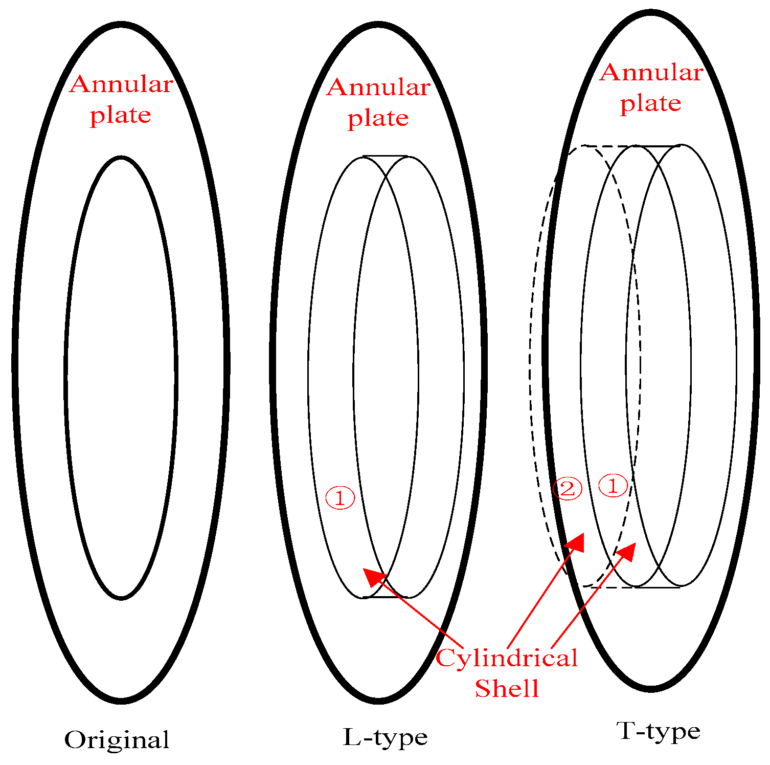
2.3. Ribbed Structural Form

In order to increase the strength of the structure in underwater vehicles, ribs are often added. In this paper, an annular plate with conical shell degradation is used to simulate and strengthen the rib structure. Similarly, the connection between the conical shell and the annular plate needs to meet the conditions of displacement continuity and internal force balance. Adopting the splicing method in finite element analysis, assemble the conical shell with the annular plate to simulate the overall stiffness matrix of the ribbed conical shell. In actual underwater vehicles, the ribbed structure includes not only smooth flat annular plates but also T-shaped ribs and L-shaped ribs. These two types of rib structures can also be obtained by splicing annular plates with narrow cylindrical shells.
The three types of ribbed structures are shown in Figure 4. The flat plate ribbed structure only requires a single annular plate, which is referred to as the original type in this article. The L-shaped ribbed structure requires a small cylindrical shell to be joined at the inner diameter of the circular ring plate, while the T-shaped ribbed structure requires two small cylindrical shells to be joined at the inner diameter of the circular ring plate. The splicing method of the three ribbed structural forms is consistent with the structural form in (f) of Figure 2.

2.4. Application of Boundary Conditions

In the traditional literature [34], boundary conditions are often related to the axial wavenumber in the shell, while the calculation method proposed in this paper can achieve arbitrary boundary conditions through artificial springs using elastic boundary conditions. The implementation of artificial springs can be achieved by installing springs k on the corresponding degree-of-freedom elements in the overall stiffness matrix. When k approaches 0, the entire model is under free boundary conditions. When k is relatively large, such as k = 1020 N/m and above, the entire model is under rigid fixed boundary conditions. The stiffness k can take any corresponding value to achieve complex elastic boundaries. The implementation of arbitrary boundaries for artificial springs can be applied to a specific degree of freedom, such as the axial, tangential, radial, or rotational direction of a conical shell, or simultaneously applied to several degrees of freedom, achieving the difficult outcome that classical boundaries in traditional shells cannot manage.

2.5. Response Solving

By solving the determinant value of the overall dynamic stiffness matrix of the combined shell, the natural frequency of the overall combined shell structure can be obtained from the maximum and minimum values of the determinant value. We apply a force load to the left side of the overall dynamic stiffness matrix and obtain the response on the right side of the equation by inverting the matrix.
For example, in the conical–cylindrical coupled structure shown in Figure 2, if a unit radial force is applied on edge ➀, which can be written as F 1 = [ 0 0 1 0 ] , according to Equation (12), the response of the composite shell can be written as
U 1 U * U 4 = D 11 D 12 0 D 21 D 22 + D 33 D 34 0 D 43 D 44 1 F 1 F * F 4
Therefore, it can be applied separately or simultaneously in any circumferential direction of the three edges.

3. Numerical Discussion

3.1. Conical Shell Verification

In this paper, the dynamic stiffness matrix of the conical shell is the basis. To verify the correctness of the solution results for the conical shell presented in the previous section, this paper first compares and verifies the natural frequency of the free vibration of the conical shell with the literature, as shown in Table 1 and Table 2. According to the literature [32,35], the dimensionless frequency of a conical shell is defined as ω c = R 2 ω E / 1 μ 2 ρ , where the small-end radius of the conical shell is R1 and the large-end radius is R2. The geometric dimensions of the conical shell are R 2 / h = 100 , and according to the literature, the cone apex angle of the conical shell satisfies L sin α / R 2 = 0.25 , in which α is the semi-vertex angle. The entire conical shell is made of isotropic and uniform material, with a Poisson’s ratio of μ = 0.3. Since the dimensionless natural frequency is used above, there is no need to set the density value of a specific material. This article compares the natural frequencies of three semi-vertex angle models of conical shells under two boundary conditions: simply supported at both ends, and simply supported at the small end and fixed supported at the large end.
From the above two tables, it can be seen that the dimensionless natural frequency calculation results for the conical shell in the present article are largely consistent with the calculation results in the literature, which proves the correctness of the calculation method. The displacement response of the conical shell in formula (3) requires the superposition of the power series m, but in practical examples, the power series m needs to be truncated, and it is impossible to take an infinite number of series. Therefore, the calculation cost should be minimized as much as possible while ensuring the calculation accuracy.

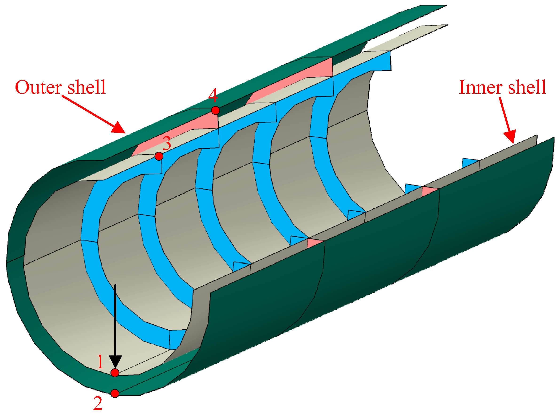
3.2. Double-Layered Cylindrical Shell Model

Furthermore, under the premise of verifying the correctness of a single conical shell, this article degenerates the conical shell into an annular plate and a cylindrical shell, and it splices them into a typical double-layered ribbed cylindrical shell structure in underwater vehicles. The calculation model is as follows: the left end of the inner shell is a fixed boundary, and the right end is a free boundary. The left and right ends of the outer shell are both free boundaries. There are four positions marked on the diagram: 1, 2, 3, and 4. We apply a harmonic force along the radial direction of the pressure-resistant shell at position 1. A schematic diagram of the double-layered cylindrical shell is shown in Figure 5, where white is the inner shell, green is the outer shell, pink is the solid rib plate, and blue is the reinforced rib.
The length of the entire double-layered cylindrical shell is 3.0 m, and the spacing between the solid rib plates is 1.0 m. The outer shell radius is 0.6 m, and the inner shell radius is 0.5 m. The width of both the solid rib plate and the internal rib is 0.1 m. The entire model is a homogeneous isotropic material with a density of 7800 kg/m3, a Young’s modulus of 210 GPa, and a Poisson’s ratio of 0.3.
Because finite element analysis is used to verify the calculation results, it is necessary to first conduct a mesh convergence analysis of the computational model. For the double-layered cylindrical shell model, this article divides it into four types of coarse and fine mesh models based on the size of the mesh, as shown in Figure 6.
The total length of the double-layered cylindrical shell is 3.0 m, and the average rib spacing of the pressure-resistant shell is 0.5 m, with a total of five ribs. The average rib spacing of the light outer shell is 1.0 m, with a total of two fenders. For the convenience of calculation, both the inner and outer shells have a thickness of 10 mm. When the mesh size is 0.01 m, there are 231,115 elements and the total calculation time is 112,955 s; when the mesh size is 0.02 m, there are 67,643 elements and the total calculation time is 22,196 s; when the mesh size is 0.05 m, there are 9207 elements and the total calculation time is 2123.5 s; and when the mesh size is 0.1 m, there are 2336 elements and the total calculation time is 446.20 s.
Because the cylindrical shell is a symmetrical structure, point excitation loads can be applied to any point on the cross-section of the conical shell, and the calculated results are the same. The applied force in this article is at point P1. A comparison of radial and axial displacements at point 1 of the finite element model under four different grid sizes is shown in Figure 7. It can be seen that the finite element model calculation results of different grids largely overlap in the low-frequency range (1–100 Hz). As the frequency increases, the calculation results of different grids deviate, and the thicker the grid, the more the resonance peak moves towards the high frequency. Moreover, the calculation results with a grid size of 0.02 m largely overlap with those with a grid size of 0.01 m. When considering the calculation times of the four grid models, in order to save computing resources and ensure calculation accuracy, a finite element model with a grid size of 0.02 m is selected in this article.
The comparison between the calculation results of the four positions, from point 1 to point 4, and the finite element vibration response calculation is as follows in Figure 8, Figure 9, Figure 10 and Figure 11.
From the above figures, it can be seen that the axial displacement and radial displacement calculated in this article are consistent with the FEM calculation results, proving the correctness of the calculation method. Within the 500 Hz range, the resonance peak frequencies of the two displacements are consistent, but the amplitudes are not the same. In modal analysis, although there is no axial mode, the radial mode has an impact on axial displacement. We propose that this is due to the coupling effect of solid rib plates in the double-layered cylindrical shell. Moreover, the radial mode also affects the axial displacement response.
Furthermore, this paper examines the effects of the rib form. On the premise of ensuring that the geometrical model of the double-layered cylindrical shell remains unchanged, the width of the L-shaped rib web is 0.025 m, and the width of the T-shaped rib web is 0.025 × 2 = 0.05 m, which is symmetrical on both sides, as shown in Figure 4 for small cylindrical shells ➀ and ➁.
Under the premise of keeping the boundary conditions unchanged, the comparison of radial and axial vibration displacement responses of the double-layered cylindrical shell at points 1 and 2 under different ribbed structures is shown in the following Figure 12.
From the above figure, it can be seen that under different rib forms, in the low-frequency range of 100 Hz, the responses of point 1 and point 2 on the double-layered cylindrical shell are not significantly affected by different rib forms. The impact on point 1 on the inner shell is more obvious in the range of 200–300 Hz. Among them, the stiffness of the T-shaped rib is the highest, followed by the stiffness of the L-shaped rib, and the stiffness of the original rib is the smallest. Therefore, it can clearly be seen from the figure that the resonance peak frequency in the displacement response under the T-shaped rib is the highest. For point 2 on the shell, there is an influence in the frequency range of 100–300 Hz, and the resonance peak frequency of the response is highest under the same T-shaped rib.
The circumferential mode number n is one of the key parameters in solving the response of conical shells. Therefore, this paper first investigates the convergence of circumferential mode numbers for the double-layered cylindrical shell example model mentioned above.
From Figure 13, it can be seen that when the number of circumferential modes is n = 20, the radial and axial displacement responses at point 1 converge and remain unchanged. When the number of circumferential modes is set to 5, there is no difference in the response curve in the low-frequency range. However, as the frequency increases, the complete information of the circumferential mode number cannot be captured after 300 Hz. Therefore, in order to save computing resources in this article, the number of circumferential modes n = 20 is taken in the calculation.
The solid rib plate is an important channel for transmitting the vibration of the inner cylindrical shell to the outer cylindrical shell. This paper studies the influence of the thickness of the solid rib plate on the vibration of the double-layered cylindrical shell, with three thicknesses, of 0.01 m, 0.03 m, and 0.05 m, respectively.
From Figure 14, it can be seen that the thickness of the solid rib plate in the middle of the double-layered cylindrical shell has no effect on the low-frequency response. As the thickness of the solid rib increases, the peak in the response curve shifts towards the high-frequency range. This is because the thickness of the solid rib plate increases the stiffness of the double-layered cylindrical shell.
In addition, the number of solid rib plates between the sides is also an important transmission channel between the double-layered cylindrical shells. This article calculates the vibration response of each detection point under three conditions: 1, 2, and 5 solid rib plates.
From Figure 15, it can be seen that increasing the number of solid rib plates in the middle of the double-layered cylindrical shell increases its stiffness and reduces the number of resonance peaks in the low-frequency range. If the vibration response monitoring point is located exactly on the solid rib plate, the vibration attenuation will be more pronounced.

3.3. Influence of Elastic Boundaries

To validate the applicability of the computational method proposed in this paper to arbitrary elastic boundary conditions, a comparison is conducted with the natural frequencies of a double-layered cylindrical shell under the elastic boundaries reported in Reference [27]. The dimensions are as follows: radii of inner and outer shells R1 = 3.5 m and R2 = 4.3 m, total length L = 9.6 m, and thickness of shells and annular plates h1 = h2 = hp = 0.03 m. Shells and annular plates are made of the same material, with a Young’s modulus E = 210 GPa, density ρ = 7800 kg/m3, and Poisson’s ratio μ = 0.3.
According to the literature [28], EI denotes that axial displacement is only elastically restrained with an appropriate stiffness constant while the other three displacements are completely restrained. EII indicates that only circumferential displacement is elastically restrained. EIII is the combination of EI and EII, which means axial and circumferential displacements are elastically restrained. A comparison between the calculated natural frequencies of the double-layered cylindrical shell under an elastic boundary and the results in the literature is shown in Table 3. It can be seen that under the elastic boundary, the calculation results in this paper are largely consistent with the wave method results in the literature.
Furthermore, this article investigates the influence of elastic stiffness in four degrees of freedom on the natural frequency of a double-layered cylindrical shell at its two end boundaries.
Figure 16 shows the effect of the elastic boundary on the natural frequency of a double-layered cylindrical shell. The left figure shows the variation in the natural frequency of the double-layered cylindrical shell in the circumferential, radial, axial, and torsional directions when the elastic stiffness changes from 101 N/m to 1018 N/m under the E-C boundary. Under the E-C boundary, the radial stiffness has the most significant effect on the natural frequency of the double-layered cylindrical shell. In the range of 106 to 109 N/m, the natural frequency increases significantly. When the stiffness is greater than 109 N/m, the natural frequency tends to converge and stabilize; that is, it is assumed to be a fixed boundary under this degree of freedom. From the figure, it can be seen that the radial stiffness has the most significant impact, followed by the axial stiffness. The change in torsional stiffness has almost no effect, because the natural frequency of the double-layered cylindrical shell itself is relatively high, so the effect of the change in torsional stiffness is not significant.
To investigate the effect of elastic boundary stiffness on the natural frequency, this paper calculates and analyzes the dynamic stiffness of a double-layered cylindrical shell in three directions. In the free state at both ends, the origin dynamic stiffness in the circumferential, radial, and axial directions at point P1 is shown in the following figure. From Figure 17, it can be seen that the magnitude of the origin stiffness in the three directions is in the range of 106 to 109 N/m. Therefore, when the elastic stiffness changes within this frequency range, it affects the natural frequency of the double-layered cylindrical shell.
Through calculation and comparison, it was found that when the constraint stiffness on the elastic boundary is close in magnitude to the dynamic stiffness value on the corresponding degree of freedom at that point, the influence of the elastic boundary change is the greatest.

4. Conclusions

This article uses the spectral element method (SEM) to establish a dynamic model of a double-layered cylindrical shell (or other combined shell structures) under arbitrary boundaries, starting from the vibration control equation of a conical shell, and carries out finite-element-based calculation method verification. This calculation method will help the acoustic designer of an underwater vehicle by providing a vibration analysis tool.
The vibration characteristics were studied from the perspectives of free vibration and forced vibration, and the following conclusions can be drawn:
(1)
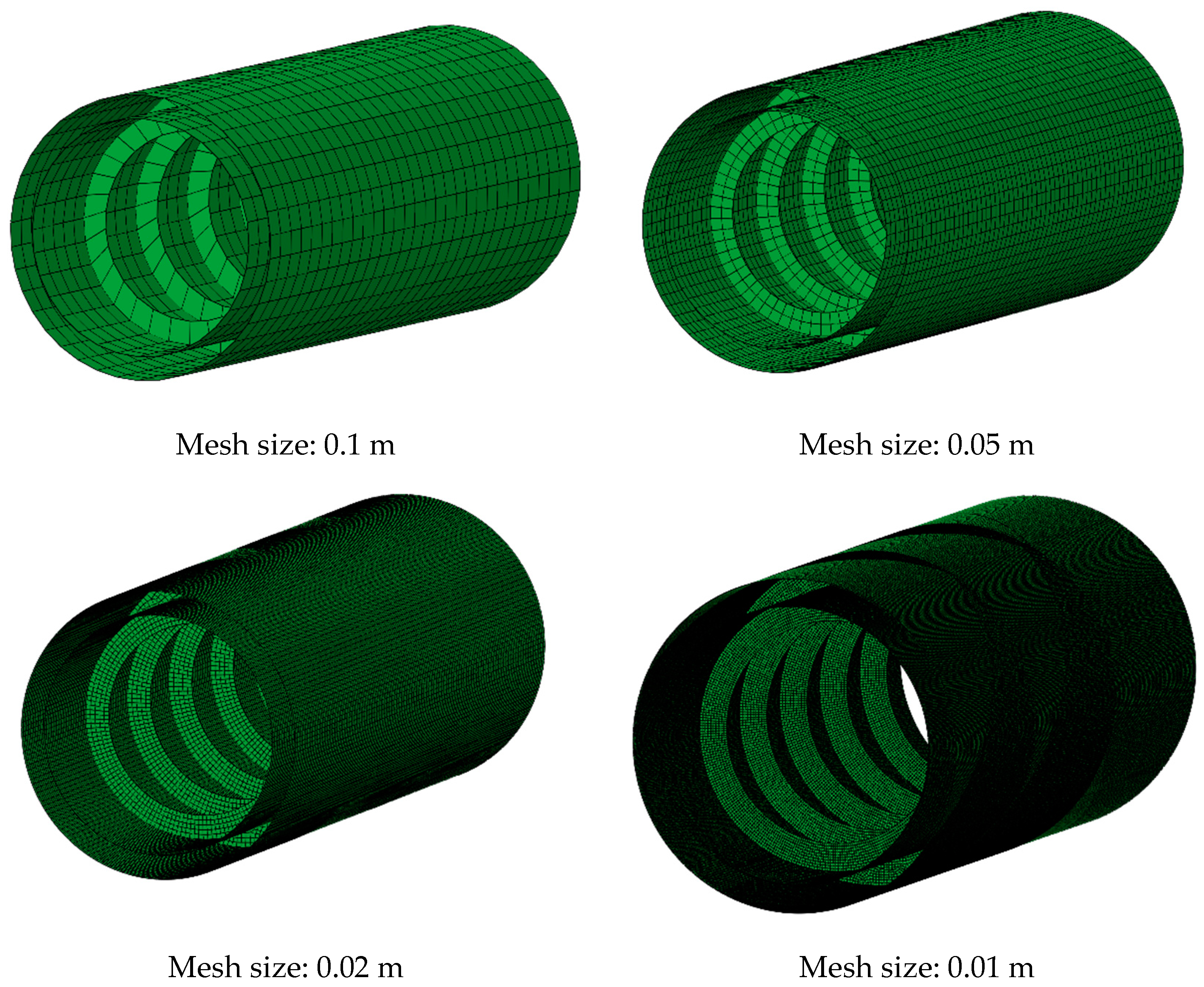
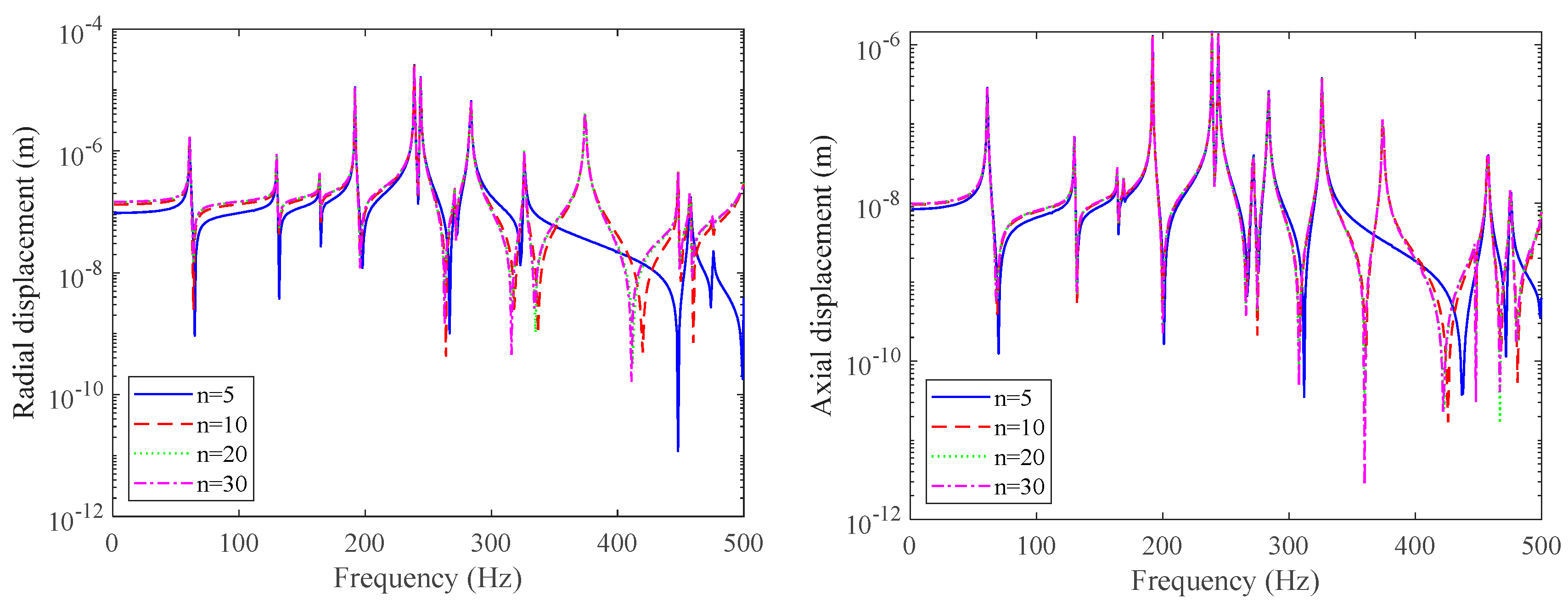
This method is based on analytical methods and does not require excessive mesh division for combined shell structures. For combined structures, without the need to derive cylindrical shells or even more complex structures such as double-layered cylindrical shells, starting from the dynamic stiffness matrix of a single conical shell, this method can be applied to various common combined shell structures. The calculation method in this article is correct and can effectively model the dynamics of combined shell structures such as conical shells and double-layered cylindrical shells. It has the advantages of a high computational efficiency and fast convergence;
(2)
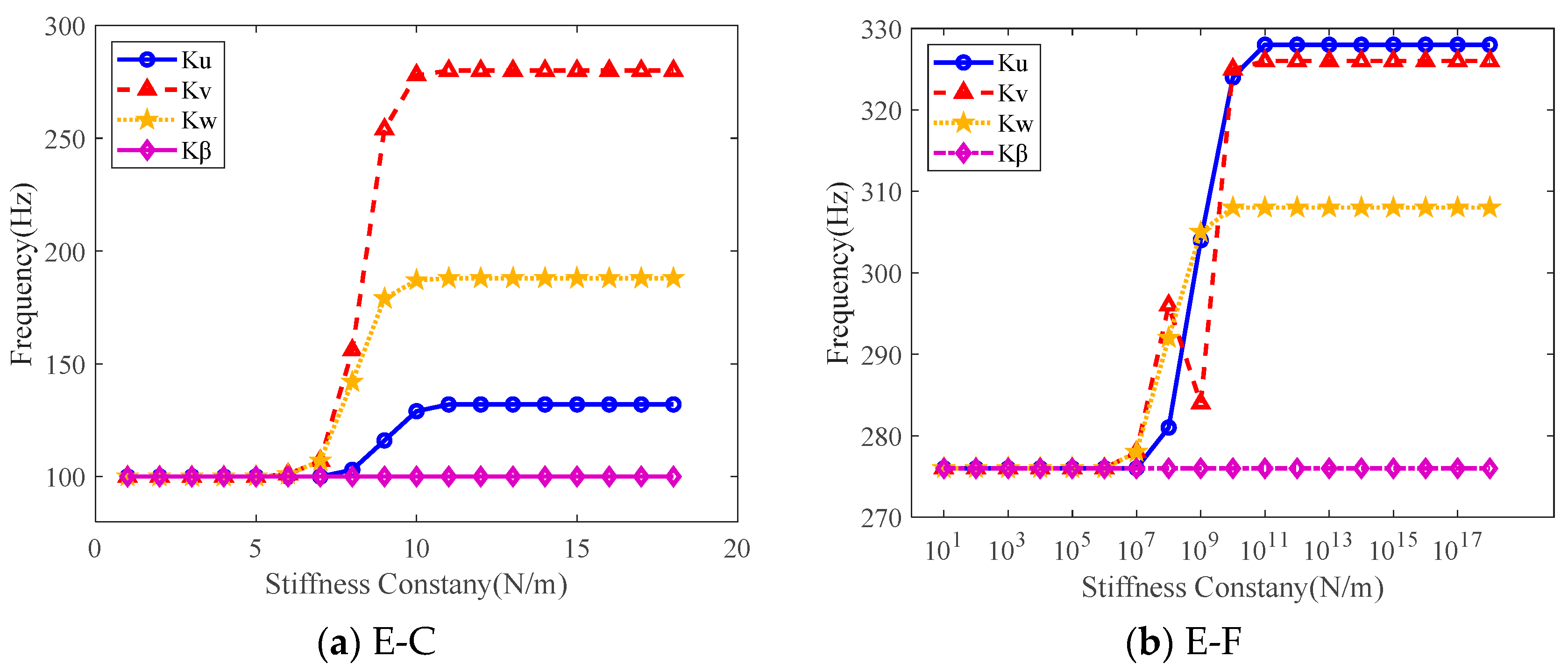
The calculation method proposed in this article is applicable to any boundary condition and is not limited to the classical boundaries in the traditional literature. Through parametric analysis, we found that the arbitrary boundary stiffness of the combined shell is related to its own origin dynamic stiffness value. When the elastic stiffness in any direction at both ends of the combined shell is of the same magnitude as the dynamic stiffness in that direction, the influence of elastic boundary stiffness on the natural frequency of the double-layered cylindrical shell becomes more significant;
(3)
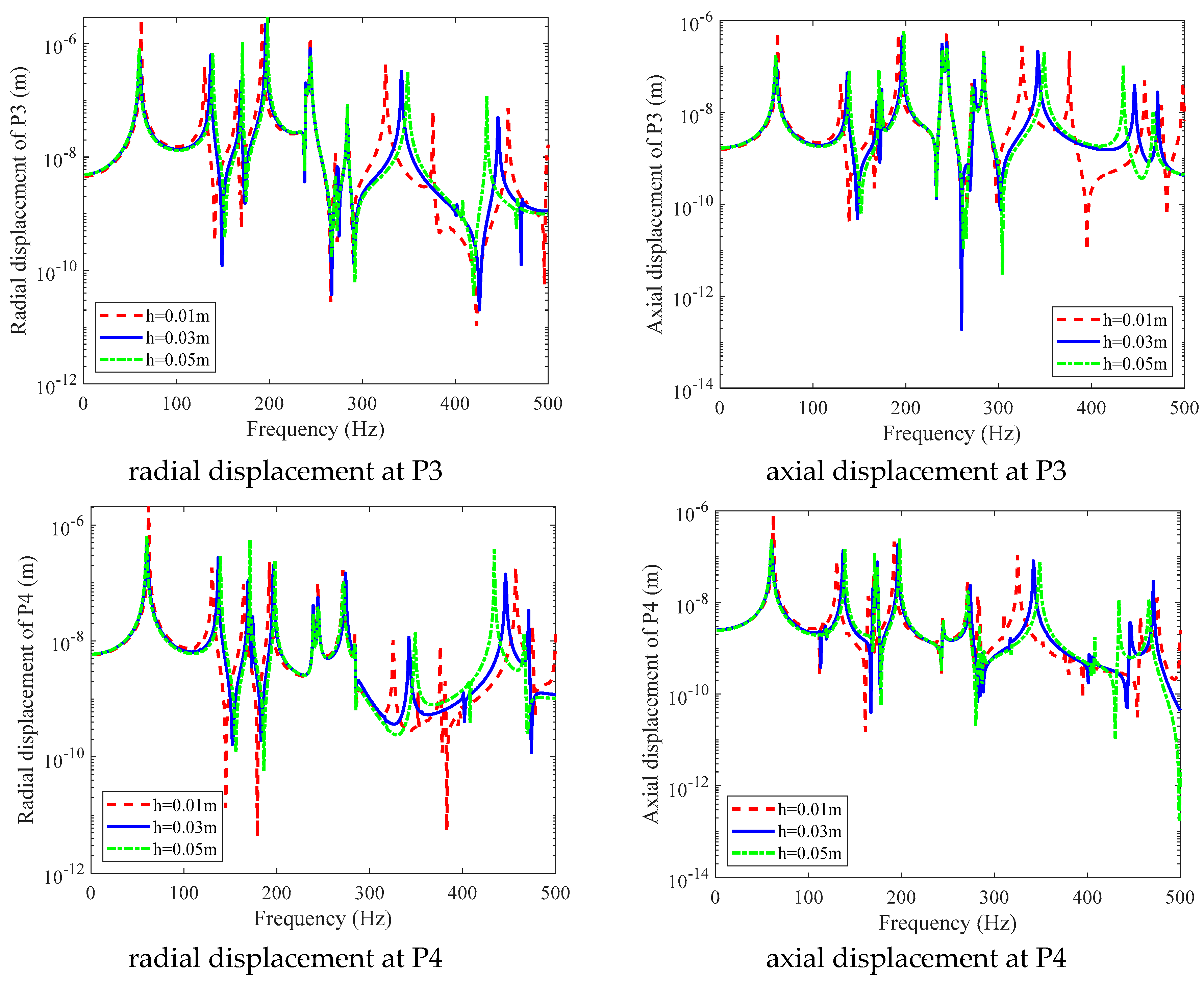
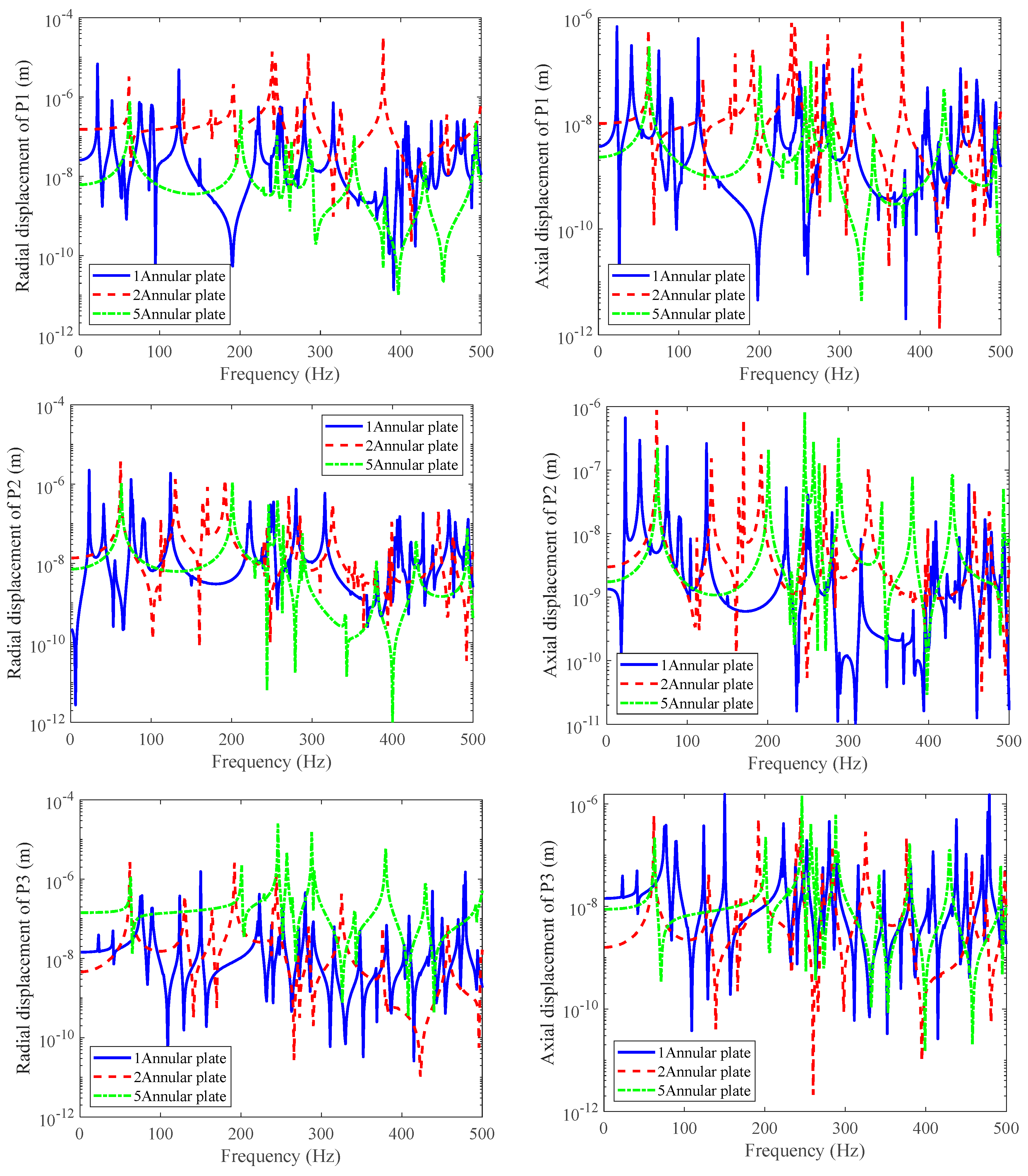
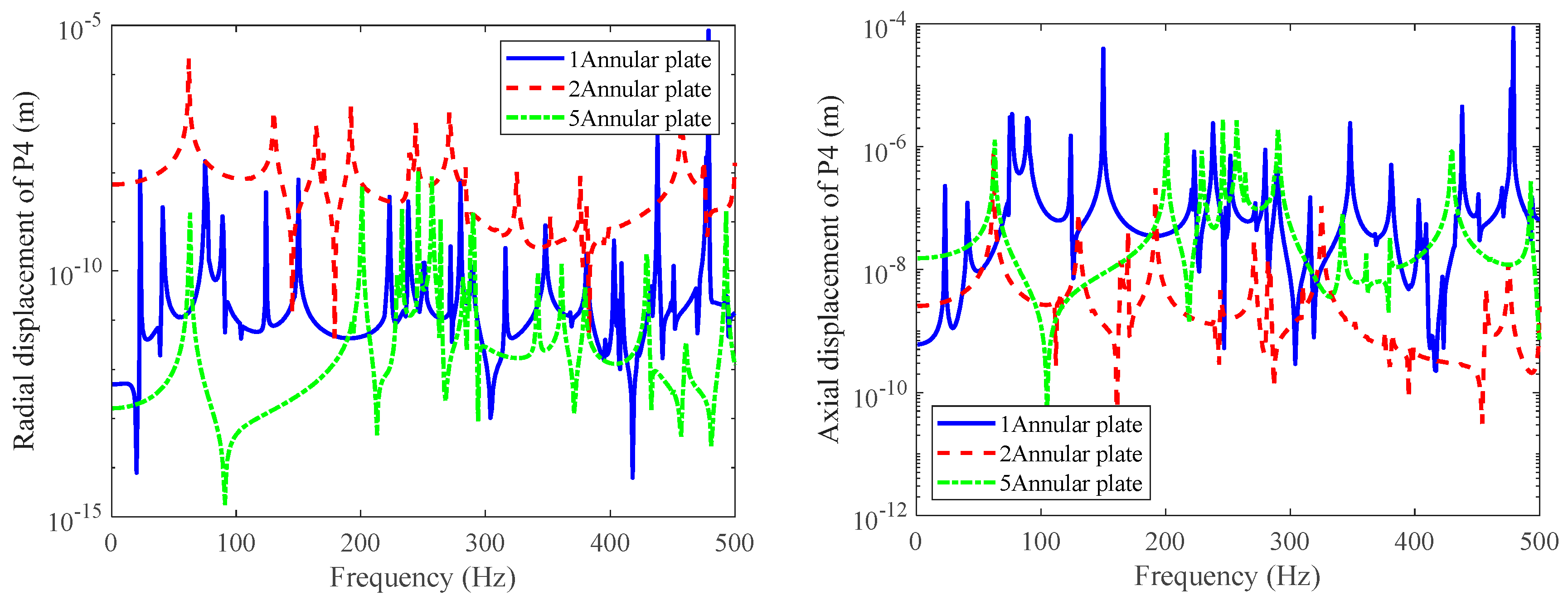
The parameters of the solid rib plate between the reinforced ribs and the double-layered cylindrical shell have an impact on the natural frequency of the combined shell. Different rib forms have little effect on the low-frequency response, and the T-shaped ribs have the highest stiffness and therefore the highest natural frequency value. The thickness of the middle solid rib plate has a relatively small impact on low frequencies, while the number of solid rib plates has a significant impact on the response throughout the entire frequency band.

Author Contributions

Conceptualization, J.W.; methodology, J.W.; software, H.Z.; validation, H.Z. and J.W.; investigation, H.Z.; writing—original draft preparation, J.W.; writing—review and editing, Y.D.; supervision, Y.D.; funding acquisition, J.W. All authors have read and agreed to the published version of the manuscript.

Funding

This research was funded by the National Natural Science Foundation of China (NSFC), grant number 12374447, and the Wuxi Young Science and Technology Talent Support Program, grant number TJXD-2024-110.

Data Availability Statement

The data presented in this study are available upon request.

Conflicts of Interest

The authors declare no conflicts of interest.

References

  1. Bahrami, S.; Shirmohammadi, F.; Saadatpour, M.M. Vibration analysis of thin shallow shells using spectral element method. Appl. Math. Model. 2017, 44, 470–480. [Google Scholar] [CrossRef]
  2. Thinh, T.I.; Nguyen, M.C. Dynamic stiffness method for free vibration of composite cylindrical shells containing fluid. Appl. Math. Model. 2016, 40, 9286–9301. [Google Scholar] [CrossRef]
  3. Qatu, M.S. Recent research advances in the dynamic behavior of shells: 1989–2000, Part 2: Homogeneous shells. Appl. Mech. Rev. 2002, 55, 415–434. [Google Scholar] [CrossRef]
  4. Qu, Y.; Chen, Y.; Long, X.; Hua, H.; Meng, G. A modified variational approach for vibration analysis of ring-stiffened conical–cylindrical shell combinations. Eur. J. Mech.-A/Solids 2013, 37, 200–215. [Google Scholar] [CrossRef]
  5. Jin, G.; Ye, T.; Jia, X.; Gao, S. A general Fourier solution for the vibration analysis of composite laminated structure elements of revolution with general elastic restraints. Compos. Struct. 2014, 109, 150–168. [Google Scholar] [CrossRef]
  6. Zou, M.S.; Liu, S.X.; Qi, L.B. An analytical formulation for the underwater acoustic radiation of a cylindrical shell with an internal flexural floor based on the reciprocity theorem. Appl. Acoust. 2019, 154, 18–27. [Google Scholar] [CrossRef]
  7. Zhu, H.; Wu, J. A Study on the Vibration Analysis of Thick-Walled, Fluid-Conveying Pipelines with Internal Hydrostatic Pressure. J. Mar. Sci. Eng. 2023, 11, 2338. [Google Scholar] [CrossRef]
  8. Yin, C.; Lei, Z.; Jin, Z.; Shi, Z. Effects of Connecting Structures in Double-Hulled Water-Filled Cylindrical Shells on Shock Wave Propagation and the Structural Response to Underwater Explosion. J. Mar. Sci. Eng. 2024, 12, 1949. [Google Scholar] [CrossRef]
  9. Leissa, A.W. Vibration of Shells; Scientific and Technical Information Office, National Aeronautics and Space Administration: Washinton, DC, USA, 1973. [Google Scholar]
  10. Amabili, M.; Païdoussis, M.P. Review of studies on geometrically nonlinear vibrations and dynamics of circular cylindrical shells and panels, with and without fluid-structure interaction. Appl. Mech. Rev. 2003, 56, 349–381. [Google Scholar] [CrossRef]
  11. Khorasani, M.; Elahi, H.; Eugeni, M.; Lampani, L.; Civalek, O. Vibration of FG porous three-layered beams equipped by agglomerated nanocomposite patches resting on Vlasov’s foundation. Transp. Porous Media 2022, 142, 157–186. [Google Scholar] [CrossRef]
  12. Kolarević, N.; Nefovska-Danilović, M.; Petronijević, M. Dynamic stiffness method in the vibration analysis of circular cylindrical shell. Građevinski Materijali i Konstrukcije 2016, 59, 45–61. [Google Scholar] [CrossRef]
  13. Kolarević, N.; Nefovska-Danilović, M. Dynamic stiffness–based free vibration study of open circular cylindrical shells. J. Sound Vib. 2020, 486, 115600. [Google Scholar] [CrossRef]
  14. Zhu, H.; Wu, J. Free vibration of partially fluid-filled or fluid-surrounded composite shells using the dynamic stiffness method. Acta Mech. 2020, 231, 3961–3978. [Google Scholar] [CrossRef]
  15. Zhang, C.; Jin, G.; Wang, Z.; Sun, Y. Dynamic stiffness formulation and vibration analysis of coupled conical-ribbed cylindrical-conical shell structure with general boundary condition. Ocean. Eng. 2021, 234, 109294. [Google Scholar]
  16. Zhang, C.; Jin, G.; Ma, X.; Ye, T. Vibration analysis of circular cylindrical double-shell structures under general coupling and end boundary conditions. Appl. Acoust. 2016, 110, 176–193. [Google Scholar] [CrossRef]
  17. Li, Z.; Jin, G.; Ye, T.; Yang, T.J.; Zhong, S.; Tian, L. A unified vibration modeling of open cylindrical shell-rectangular plate coupling structures based on the dynamic stiffness method. J. Sound Vib. 2023, 563, 117870. [Google Scholar] [CrossRef]
  18. Li, Z.; Ye, T.; Jin, G.; Yang, T.J.; Tian, L.; Chen, Y. Dynamic stiffness formulation for vibration analysis of an open cylindrical shell and its coupling structures based on a generalized superposition method. J. Sound Vib. 2022, 538, 117237. [Google Scholar] [CrossRef]
  19. Chen, M.; Xie, K.; Jia, W.; Xu, K. Free and forced vibration of ring-stiffened conical–cylindrical shells with arbitrary boundary conditions. Ocean. Eng. 2015, 108, 241–256. [Google Scholar] [CrossRef]
  20. Xie, K.; Chen, M.; Li, Z. Free and forced vibration analysis of ring-stiffened conical–cylindrical–spherical shells through a semi-analytic method. J. Vib. Acoust. 2017, 139, 031001. [Google Scholar] [CrossRef]
  21. Tian, L.; Ye, T.; Jin, G. Vibration analysis of combined conical-cylindrical shells based on the dynamic stiffness method. Thin-Walled Struct. 2021, 159, 107260. [Google Scholar] [CrossRef]
  22. Tian, L.; Jin, G.; He, T.; Ye, T.; Liu, Z.; Khadimallah, M.A.; Li, Z. A hybrid analytic–numerical formulation for the vibration analysis of a cylindrical shell coupled with an internal flexural floor structure. Thin-Walled Struct. 2023, 183, 110382. [Google Scholar] [CrossRef]
  23. Wu, J.; Sun, Y. An exact solution for vibration analysis of pipe coupled with conical-ring stiffened cylindrical shells with arbitrary boundary condition. Ocean. Eng. 2022, 266, 112861. [Google Scholar] [CrossRef]
  24. Wu, J.; Sun, Y.; Duan, Y. Exact solutions for free and forced vibrations of cross-ply composite laminated combined conical–cylindrical shells with arbitrary boundary conditions. Ocean. Eng. 2023, 285, 115371. [Google Scholar] [CrossRef]
  25. Wang, X.; Xu, E.; Jiang, C.; Wu, W. Vibro-acoustic behavior of double-walled cylindrical shells with general boundary conditions. Ocean. Eng. 2019, 192, 106529. [Google Scholar] [CrossRef]
  26. Yu, A.; Zhao, Y.; Chen, Q.; Liu, J.; Zhou, Z.; Cao, X. Vibration transmission analyses of double-layer cylindrical shell with fully immersed elastic connections through experimental and analytical approaches. Thin-Walled Struct. 2024, 199, 111781. [Google Scholar] [CrossRef]
  27. Xie, K.; Jia, W.; Dong, W.; Chen, M. Vibro-acoustic analysis of double-walled cylindrical shells through a novel semi-analytic method. Eur. J. Mech.-A/Solids 2022, 94, 104559. [Google Scholar] [CrossRef]
  28. Xie, K.; Chen, M. Wave based method for vibration analysis of double-walled cylindrical shells. Appl. Acoust. 2018, 139, 293–306. [Google Scholar] [CrossRef]
  29. Xie, K.; Chen, M.; Li, Z. An analytic method for free and forced vibration analysis of stepped conical shells with arbitrary boundary conditions. Thin-Walled Struct. 2017, 111, 126–137. [Google Scholar] [CrossRef]
  30. Jia, W.; Chen, M.; Zhou, Z.; Xie, K. Vibration analysis of double-walled cylindrical shells interconnected with arbitrary connections using a unified semi-analytical method. Ocean. Eng. 2022, 251, 110879. [Google Scholar] [CrossRef]
  31. Zhang, Y.; Shi, D.; He, D. Vibration characteristics of a laminated composite double-cylindrical shell system coupled with a variable number of annular plates. Materials 2022, 15, 4246. [Google Scholar] [CrossRef]
  32. Yoshikawa, S.; Williams, E.G.; Washburn, K.B. Vibration of two concentric submerged cylindrical shells coupled by the entrained fluid. J. Acoust. Soc. Am. 1994, 95, 3273–3286. [Google Scholar] [CrossRef]
  33. Caresta, M.; Kessissoglou, N.J. Free vibrational characteristics of isotropic coupled cylindrical–conical shells. J. Sound Vib. 2010, 329, 733–751. [Google Scholar] [CrossRef]
  34. Zhang, X.M.; Liu, G.R.; Lam, K.Y. Coupled vibration analysis of fluid-filled cylindrical shells using the wave propagation approach. Appl. Acoust. 2001, 62, 229–243. [Google Scholar] [CrossRef]
  35. Tong, L. Free vibration of composite laminated conical shells. Int. J. Mech. Sci. 1993, 35, 47–61. [Google Scholar] [CrossRef]
  36. Irie, T. Natural frequencies of truncated conical shells. J. Sound Vib. 1984, 92, 447. [Google Scholar] [CrossRef]
Figure 1. Schematic diagram of forces and displacements in conical shell.
Jmse 13 00641 g001
Figure 2. Multiple shell combination splicing methods.
Jmse 13 00641 g002
Figure 3. Splicing structure of conical shell and cylindrical shell.
Jmse 13 00641 g003
Figure 4. Three forms of ribbed structures.
Jmse 13 00641 g004
Figure 5. Double-layered cylindrical shell.
Jmse 13 00641 g005
Figure 6. Different mesh size models of double-layered cylindrical shell.
Jmse 13 00641 g006
Figure 7. Convergence analysis of radial and axial displacement at point 1 under different mesh grids.
Jmse 13 00641 g007
Figure 8. Displacement comparison for point 1.
Jmse 13 00641 g008
Figure 9. Displacement comparison for point 2.
Jmse 13 00641 g009
Figure 10. Displacement comparison for point 3.
Jmse 13 00641 g010
Figure 11. Displacement comparison for point 4.
Jmse 13 00641 g011
Figure 12. Vibration displacement responses under different rib forms.
Jmse 13 00641 g012
Figure 13. Convergence analysis of radial and axial displacement at point 1 under different circumferential modal numbers.
Jmse 13 00641 g013
Figure 14. The influence of the solid rib thickness on radial and axial displacements.
Jmse 13 00641 g014
Figure 15. The influence of different numbers of solid rib plates on the responses of the four measuring points.
Jmse 13 00641 g015aJmse 13 00641 g015b
Figure 16. Effects of elastic boundary stiffness on frequencies: (a) E-C, (b) E-F.
Jmse 13 00641 g016
Figure 17. Impedance comparison in three directions of double-layered cylindrical shell.
Jmse 13 00641 g017
Table 1. Verification of natural frequencies of simply supported conical shells at both ends.
nα = 30°α = 45°α = 60°
Ref. [35]Ref. [36]PresentRef. [35]Ref. [36]PresentRef. [35]Ref. [36]Present
00.19100.19100.19000.28540.28540.28500.36280.36280.3618
10.59230.59230.59210.52540.52550.52520.47530.47540.4745
20.79100.79100.79090.68780.68790.68760.57200.57220.5714
30.72840.72840.72850.69720.69730.69710.59980.60010.5994
40.63530.63520.63540.66620.66640.66620.60480.60540.6047
50.55310.55310.55340.63010.63040.63030.60690.60770.6071
60.49490.49490.49540.60280.60320.60320.61470.61590.6153
70.46530.46530.46600.59100.59180.59200.63290.63430.6338
80.46440.46450.46540.59830.59920.59950.66320.66500.6646
90.48920.48920.49030.62450.62570.62600.70600.70840.7080
Table 2. Verification of natural frequency of a conical shell with a small-end simple support and large-end fixed support.
nα = 30°α = 45°α = 60°
Ref. [35]Ref. [36]PresentRef. [35]Ref. [36]PresentRef. [35]Ref. [36]Present
00.98890.98890.98880.88010.88010.87980.78530.78530.7844
10.95350.95350.95340.86730.86730.86700.78210.78210.7813
20.86430.86420.86420.83290.83290.83260.77380.77380.7730
30.75820.75800.75810.78760.78750.78720.76410.76400.7632
40.66290.66260.66280.74260.74240.74220.75700.75690.7562
50.59010.58960.58990.70690.70660.70650.75660.75650.7558
60.54260.54210.54250.68550.68520.68520.76550.76540.7648
70.52070.52010.52070.68090.68060.68060.78540.78530.7847
80.52320.52240.52320.69360.69320.69330.81860.81660.8161
90.54770.54680.54770.72290.72230.72260.85970.85940.8590
Table 3. Comparison of natural frequencies of double-layered cylindrical shells under elastic boundaries (Hz).
mnEI-CEII-CEIII-CEI-FEII-FEIII-F
WBMDSMWBMDSMWBMDSMWBMDSMWBMDSMWBMDSM
1199.599.586.786.886.586.632.232.239.939.930.430.4
263.463.561.261.259.259.323.924.028.628.623.924.0
367.867.968.868.966.966.939.940.039.940.039.839.8
482.382.383.183.181.981.939.639.739.639.739.639.7
588.888.989.289.388.588.635.435.535.435.535.435.5
689.289.388.588.587.787.832.232.332.232.332.232.3
782.682.982.282.281.581.531.231.331.231.331.231.3
876.576.576.376.375.976.033.433.533.433.533.433.5
21166.0166.1155.45155.5153.0153.1113.3113.4103.9104.094.094.1
2119.8119.8108.9108.9108.2108.375.976.067.367.467.167.2
3100.1100.294.494.494.394.360.460.460.460.560.360.3
497.697.794.994.994.494.546.046.046.046.046.046.0
595.495.494.094.193.393.337.037.137.037.137.037.1
690.490.589.489.489.189.234.334.434.334.434.334.4
784.484.583.483.583.083.137.437.537.437.537.437.5
879.379.379.179.278.278.343.944.043.944.043.944.0
31175.2175.3178.4178.5173.0173.1117.6117.6127.6127.7111.8111.9
2148.3148.3140.9141.0139.8139.885.685.685.986.084.884.8
3123.0123.1117.6117.7117.5117.568.068.068.468.566.566.6
4108.0108.0104.3104.4104.3104.381.481.582.282.381.181.1
598.098.195.795.795.295.388.488.588.988.988.288.3
690.790.790.790.889.589.689.189.288.588.597.787.8
784.586.484.384.484.184.282.982.982.282.281.581.5
880.780.880.981.080.580.676.776.876.576.576.076.1
41181.9191.0180.4180.5176.4176.4152.5152.6158.8158.9151.0151.0
2160.1160.2152.3152.3151.2151.3136.7136.7126.4126.4125.9125.9
3134.5134.6126.7126.8125.9126.0109.0109.1101.5101.6101.4101.5
4115.6115.7110.0110.0109.7109.8100.1100.296.496.495.995.9
5102.0102.198.798.898.698.795.795.894.194.203.393.3
691.691.790.992.290.790.890.290.389.289.389.189.2
786.386.685.685.785.185.284.584.683.583.683.183.2
882.282.382.582.681.781.779.879.879.779.878.778.8
Disclaimer/Publisher’s Note: The statements, opinions and data contained in all publications are solely those of the individual author(s) and contributor(s) and not of MDPI and/or the editor(s). MDPI and/or the editor(s) disclaim responsibility for any injury to people or property resulting from any ideas, methods, instructions or products referred to in the content.

