Article

Research on the Coupling Dynamics Characteristics of Underwater Multi-Body Separation Considering the Influence of Elastic Constraints

by
Jiahui Chen
1,
Yanhua Han
2,*,
Ruofan Li
2,
Zhenmin He
1 and
Yong Zhang
2
1
China Ship Scientific Research Center, Wuxi 214082, China
2
College of Astronautics, Nanjing University of Aeronautics and Astronautics, Nanjing 210016, China
*
Author to whom correspondence should be addressed.
J. Mar. Sci. Eng. 2025, 13(4), 627; https://doi.org/10.3390/jmse13040627
Submission received: 21 February 2025 / Revised: 18 March 2025 / Accepted: 20 March 2025 / Published: 21 March 2025

Abstract

:
Based on the Newton–Euler method, a multi-body coupling dynamics model of the separation process of underwater vehicles is established. The conditions of contact and detachment between the sub-vehicle and each group of elastic gaskets are analyzed in detail, and the elastic gasket constraint model is established to simulate the elastic contact and detachment process. Based on the Computational Fluid Dynamics (CFD) method, the hydrodynamic data of vehicles under different cases is calculated. In this context, a relatively accurate hydrodynamic database is established, where the hydrodynamic of the Unmanned Underwater Vehicle (UUV) is obtained through fitting, while those of the sub-vehicles are calculated using online interpolation. These provide conditions for realizing Fluid–Structure Interaction (FSI) calculation. Utilizing the FSI simulation method in the multi-body separation process, the separation dynamics of the multi-vehicle under the influence of elastic constraint parameters are analyzed. The simulation results show that the pitching attitude angles of the UUV and sub-vehicle in the separation process are negatively correlated with the change of elastic constraint stiffness, and the load is positively correlated with it, which are in opposite optimization directions. When the total stiffness of the elastic gaskets remains constant, changes in the number of elastic gaskets have a minimal impact on the UUV and sub-vehicle motion state during separation, but significantly affects the load fluctuations on the sub-vehicle, leading to structural vibration issues. The analysis method established in this paper is capable of quickly assessing the safety of underwater vehicle separation for different elastic gasket schemes, thereby facilitating the optimization of parameters.

1. Introduction

An Unmanned Underwater Vehicle (UUV) is capable of carrying various devices to perform specific tasks in extreme and dangerous environments, effectively replacing humans for underwater operations, and has therefore experienced rapid development. In the civilian field, UUV is widely used, including underwater surveys, marine resource development, underwater engineering construction and maintenance, as well as underwater search and rescue, which greatly improves the feasibility of underwater operations. In the military field, UUV is also used for anti-torpedo and underwater reconnaissance, providing critical intelligence and then enhancing strategic decision-making capabilities [1,2,3,4]. Under specific operating conditions, the sub-vehicle needs to be separated from the UUV to enable it to independently perform and complete assigned tasks. Therefore, it is necessary to study the dynamic characteristics of underwater vehicles in the separation process to improve their safety [5].
Firstly, this study investigated the coupling dynamics of a multi-vehicle system during the separation process. The ideas and methods for dynamics modeling of the multi-body separation process provided in the following literature served as a reference for dynamics modeling in this paper.
Han et al. [6,7] studied the two-body coupling dynamics between the carrier aircraft and the rocket during the launch process under the influence of gravity. In Ref. [6], the force conditions acting on the rocket and the degree of freedom of motion of the whole multi-body system were studied, and the launch process was segmented into five distinct stages. Utilizing the Newton–Euler approach, the coupling dynamics equations were formulated for the air launch and the carrier aircraft rocket without a launch tube. Subsequently, numerical simulations were carried out to explore the motion characteristics of the system throughout the launch process. In Ref. [7], the air-launch process was categorized into two distinct scenarios: one where the aircraft carries the rocket during flight, and the other where the rocket exits the launch tube propelled by gravity. Ultimately, the dynamics model of the launch process was established based on the Newton–Euler method, which described the motion characteristics of the multi-body system in the launch process. In the research by Wang et al. [8], the motion equations and missile launch dynamics equations for a vehicle-mounted missile system were formulated using a multi-body system analysis approach based on transfer matrix techniques and launch dynamics theory. In this study, the research object was modeled separately, and the models of each subsystem were then organically combined to obtain the whole system dynamics model. Finally, through numerical simulations, the motion characteristics of the entire launch process of the vehicle-mounted missile system were analyzed, and the correctness of the modeling was verified. In the research by Zhang et al. [9], the hydrodynamic parameters of the missile were determined by integrating experimental data with system identification methods. The study then focused on analyzing the change in the wake flow generated by the missile and constructed a mathematical model to describe the interaction forces between successive launch missiles. Using this model, the researchers were able to forecast the flight paths and orientation variations of missiles under different launch scenarios, providing a solid theoretical basis for refining launch strategies. This study initially investigated the coupling dynamics interactions between the UUV and sub-vehicle during their separation. Previous research (Refs. [6,7,8,9]) had focused on the motion coupling relationships during the separation process of multi-body systems and developed a comprehensive multi-body dynamics coupling model to describe these interactions. This has certain reference significance for this study.
Refs. [10,11,12] studied the effects of different factors on underwater projectile launches. Weiland et al. [10] investigated the effects of the relative velocity between the submarine and the horizontal flow, as well as the launch depth, on projectile launching, providing valuable reference conclusions for the initial conditions of projectile launching. Shang et al. [11] derived the dynamics model for the underwater vertical ejection of projectiles, examining how lateral flow affects their motion characteristics. It was pointed out that the projectiles were subjected to significant lateral impact during the launch process, and attention should be paid to their vibration problem. Wang et al. [12] explored the flight path characteristics of projectiles during the separation process from submarines via numerical simulation. They examined how different water flow conditions influence the motion of projectiles and determined that water velocity is a key factor in dictating the success of projectile separation. Refs. [13,14,15] were dedicated to studying the mechanical environment and fluid dynamics characteristics of missiles or underwater vehicles during underwater launch. Tan et al. [13] examined the mechanical conditions of submarines when separating projectiles horizontally, developed a ballistic dynamics model and studied the emergency countermeasures for submarines in case of projectile ignition failure. In the research conducted by Cheng et al. [14], a coupled mathematical model involving both air and water dynamics during the underwater missile launch process was established, and the interaction between air and water flow was simulated through numerical methods. The experimental results are helpful for optimizing the design of underwater launch systems. Zhang et al. [15] utilized a multi-phase flow model and dynamic grid technology to conduct 3D numerical simulations of the initial launch phase of submarine-launched missiles under cold ejection conditions. The research focused on analyzing the fluid dynamics characteristics and the formation and evolution of tail bubbles during this phase. The findings offer a crucial foundation for the development and enhancement of the performance of submarine-launched missiles. Wang et al. [16] explored how installation parameters affect the secure release of mission payloads from autonomous underwater vehicles (AUVs). The trajectory and attitude changes of the mission payload and AUV after separation were analyzed at different cruising speeds and separation depths. Li et al. [17] conducted a comprehensive analysis of the fluid dynamics and structural response of launch tubes during the underwater launch process using fluid–structure coupling numerical simulation techniques. Their study revealed that significant pressure fluctuations within the launch tube occur during the dominant cavitation period. Additionally, they found that both lateral flow velocity and launch depth have a substantial impact on the performance and structural integrity of the launch tube. These findings offer critical insights and guidance for the design optimization of launch tubes in underwater launch systems. Lv et al. [18] constructed a simulation model for the submarine vertical missile launch process, based on the submarine’s spatial motion equations. Utilizing numerical simulation results, they assessed the influence of uncertain factors on both the missile launch process and the submarine’s stability control. This research provides valuable insights into how these factors affect the overall launch dynamics and control mechanisms of submarines during missile ejection. Brito et al. [19,20] developed a numerical simulation tool based on the coupling of Smoothed Particle Hydrodynamics (SPH) and multi-body dynamics to investigate the FSI of an Oscillating Wave Surge Converter (OWSC) and a Wave Energy Hyperbaric Converter (WEHC) under complex mechanical constraints. These studies validated the model’s accuracy under nonlinear wave conditions, offering valuable reference in hydrodynamics and FSI modeling. The literature above focuses on studying the effects of underwater separation processes [21] under different working conditions on the platform, payload, launch tube and flow field, providing important references for the constraint setting and simulation condition setting in the launch tube in this paper.
In Ref. [5], the dynamics equations for the underwater separation of a multi-vehicle system under the rigid constraint of the launch tube are derived. Additionally, the impacts of various factors—such as mass ratio and separation depth—on the separation process between the UUV and the sub-vehicle are examined. Building upon the research of Ref. [5], this paper further examines the influence of elastic constraints between the launch tube and the sub-vehicle on the motion and mechanical properties of the multi-vehicle system. To enhance the realism of the simulation of the contact and separation process between the UUV and the sub-vehicle, several sets of elastic gaskets are installed within the launch tube. On this foundation, the coupling dynamics of the multi-vehicle separation process are investigated, and numerical simulations are conducted under a range of typical operating conditions.
The innovation of this paper lies in developing a complete two-rigid-body coupled dynamics model of UUV and sub-vehicle, considering the elastic gaskets in the launch tube. The analysis method established in this paper is capable of quickly assessing the safety of underwater vehicle separation for different elastic gasket schemes, thereby facilitating the optimization of parameters.

2. Multi-Vehicle Coupling Dynamics Modeling

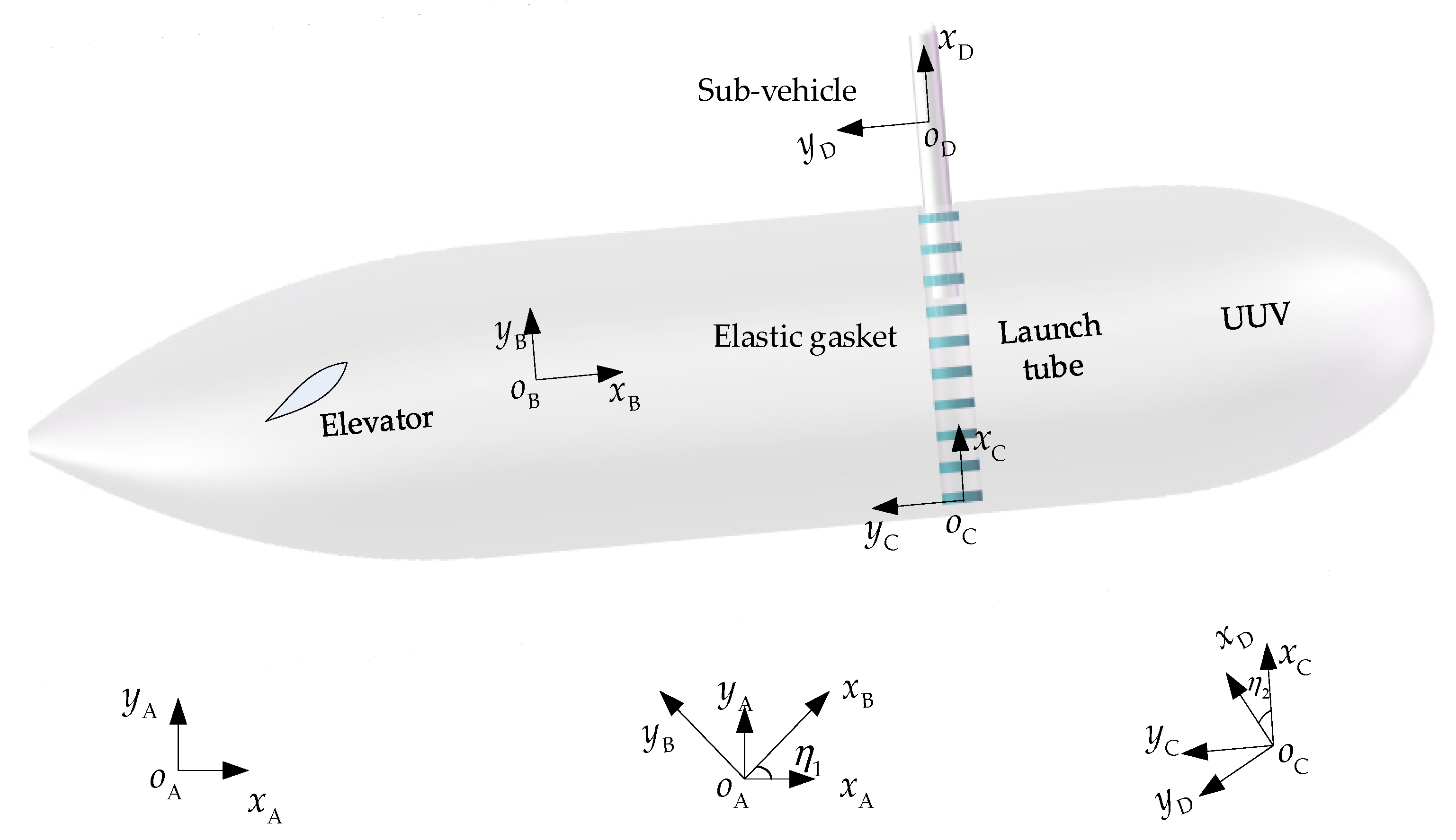
2.1. Multi-Vehicle Model and Coordinate Definition

The multi-vehicle system mentioned in this paper includes UUV and a sub-vehicle. A vertical launch tube is installed inside the UUV, which contains multiple sets of elastic gaskets, in order to restrain and buffer the sub-vehicle.
The following coordinate systems are established to describe the motion state of multiple vehicles: inertial coordinate system A( o A x A y A ), UUV Body-fixed coordinate system B( o B x B y B ), launch tube coordinate system C( o C x C y C ) and sub-vehicle Body-fixed coordinate system D( o D x D y D ). All motion is reduced into a two-dimensional plane. The position and orientation definitions of all coordinate systems are shown in Figure 1. o B and o D are the centroids of the UUV and sub-vehicle, respectively.
This paper also focuses on pitching motion. The pitch angle of the UUV relative to the A coordinate system is denoted as η 1 , while the pitch angle of the sub-vehicle relative to the launch tube is denoted as η 2 .
The model parameters of the multi-vehicle system, as well as the meanings of the subscript and superscript symbols in the formulas are shown in Table 1.
The transformation relations of vectors in different coordinate systems mentioned in this paper are as follows.
v A = T AB v B ,   v B = T BC v C ,   v C = T CD v D
where
T AB = cos η 1 sin η 1 sin η 1 cos η 1 , T BC = 0 1 1 0 , T CD = cos η 2 sin η 2 sin η 2 cos η 2
The calculation method of absolute derivative is shown in Equation (3).
d v B d t = ( v ˙ x B , v ˙ y B ) B T + ω B × ( v x B , v y B ) B T
where
ω B × = T AB T T ˙ AB = 0 η ˙ 1 η ˙ 1 0
Equations (1)–(4) will be repeatedly used in the subsequent derivation process.

2.2. Kinematic Analysis

In this section, the kinematics of UUV and sub-vehicle are given, including position, velocity, acceleration vector and moment of momentum in different coordinate systems.
The absolute position vector of the UUV’s centroid is defined by Equation (5). In this paper, absolute vectors refer to those defined relative to the origin of the inertial coordinate system A. Unless otherwise stated, vectors associated with the UUV and sub-vehicle are defined relative to their respective centroids.
r u = ( x u A , y u A ) A T
Compute the first- and second-time derivatives of Equation (5) to determine the absolute velocity and acceleration of the UUV, respectively. Subsequently, transform these quantities into the B coordinate system using Equation (1). This yields Equations (6) and (7).
v u = x ˙ u A cos η 1 + y ˙ u A sin η 1 x ˙ u A sin η 1 + y ˙ u A cos η 1 B
a u = x ¨ u A cos η 1 + y ¨ u A sin η 1 x ¨ u A sin η 1 + y ¨ u A cos η 1 B
The position vector r la u of the launch tube bottom center ( o C ) relative to the UUV is given by Equation (8), with its components in the B coordinate system being known parameters.
r la u = ( x la u , B , y la u , B ) B T
The position vector of the sub-vehicle centroid relative to the bottom center of the launch tube is given by Equation (9).
r s la = ( x s la , C , y s la , C ) C T
By transforming Equation (9) into the B system and substituting it into formula r s u = r la u + r s la , the position vector r s u of the sub-vehicle relative to UUV can be obtained. Use Equation (3) to calculate the time derivative of this vector r s u . The projection component expression of the relative velocity vector v s u between the sub-vehicle and UUV in the B coordinate system can be derived. By substituting vectors v u and v s u into formula v s = v u + v s u , the absolute velocity vector of the sub-vehicle can be determined:
v s = x ˙ u A cos η 1 + y ˙ u A sin η 1 η ˙ 1 ( y la u , B + x s la , C ) y ˙ s la , C x ˙ u A sin η 1 + y ˙ u A cos η 1 + η ˙ 1 ( x la u , B y s la , C ) + x ˙ s la , C B
Using Equation (3), compute the time derivative of the velocity vector v s to determine the absolute acceleration of the sub-vehicle.
a s = x ¨ u A cos η 1 + y ¨ u A sin η 1 η ¨ 1 ( y la u , B + x s la , C ) y ¨ s la , C η ˙ 1 2 ( x la u , B y s la , C ) 2 η ˙ 1 x ˙ s la , C x ¨ u A sin η 1 + y ¨ u A cos η 1 + η ¨ 1 ( x la u , B y s la , C ) + x ¨ s la , C η ˙ 1 2 ( y la u , B + x s la , C ) 2 η ˙ 1 y ˙ s la , C B
The moments of momentum of UUV and sub-vehicle relative to their respective centroids are given below.
h u = b 3 J u η ˙ 1
h s = b 3 J s ( η ˙ 1 + η ˙ 2 )
where b 3 is the outward unit vector perpendicular to the longitudinal plane of the multi-vehicle system.

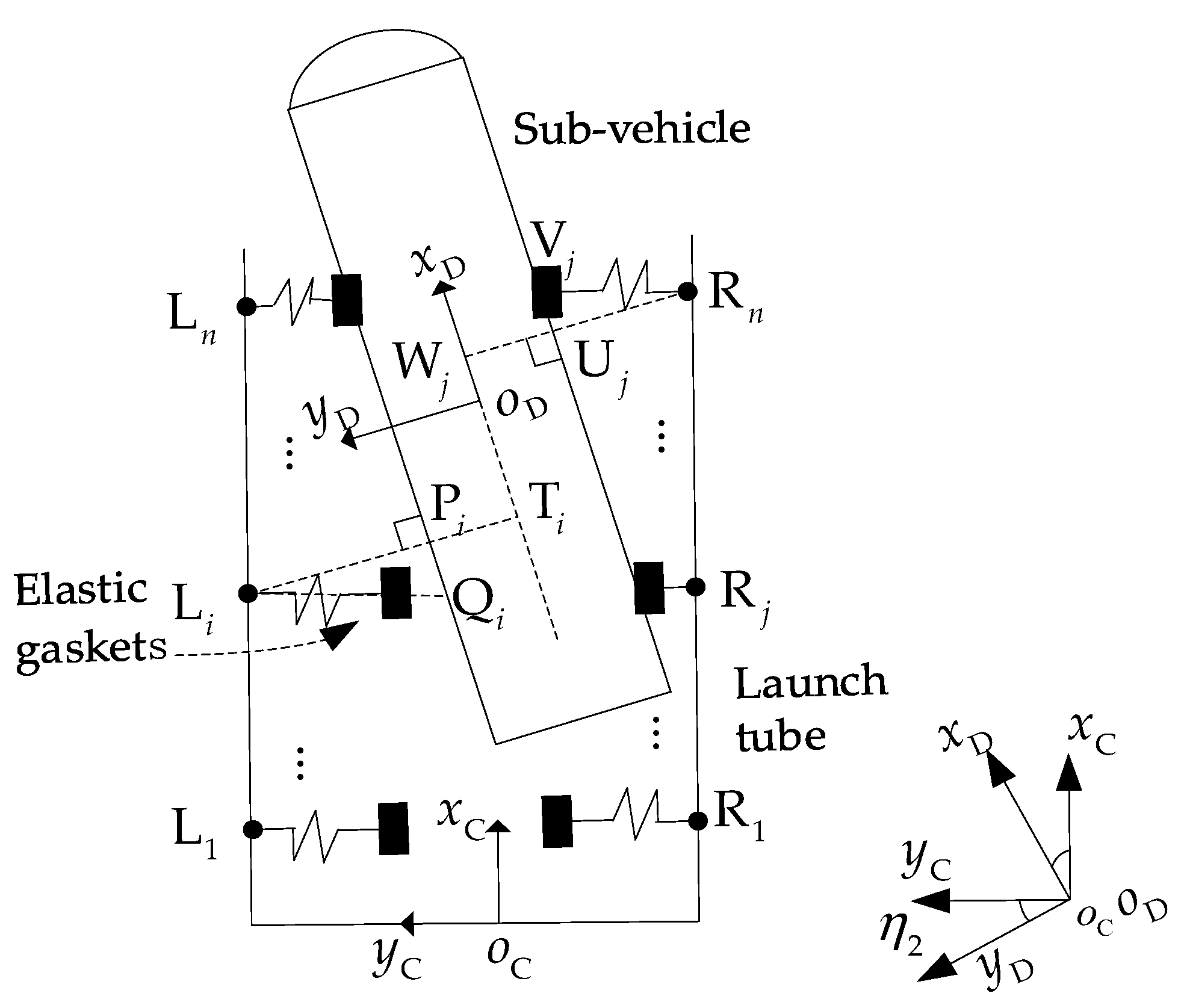
2.3. Force and Moment Analysis

The forces acting on the UUV and sub-vehicle are presented in this section, including hydraulic force, launch thrust, engine driving force, elastic constraints (elastic force) and reaction force, among others.
The hydraulic force and moment acting on the UUV are defined in the B coordinate system, as given by Equation (14).
F u w = ( F u , x w , B , F u , y w , B ) B T ,   M u w = b 3 M u w
The engine driving force F u en exerted on the UUV is assumed to act along its body-fixed longitudinal axis, with a magnitude of T . The pitch moment provided by the elevator is denoted as M u δ e .
F u en = ( T , 0 ) B T , M u δ e = b 3 M u δ e
Similarly, the hydraulic force and moment acting on the sub-vehicle are defined in the B coordinate system, as given by Equation (16).
F s w = ( F s , x w , B , F s , y w , B ) B T ,   M s w = b 3 M s w
The following is an analysis of the internal forces between the UUV and the sub-vehicle, including launch thrust and elastic constraint (elastic force). In this section, the moment centers under consideration are the centroids of the UUV and sub-vehicle.
The launch thrust f is experienced by the sub-vehicle along the longitudinal axis of its body, with a magnitude of f .
f = ( f , 0 ) D T
Assuming that the launch thrust acts at the bottom center of the sub-vehicle, the distance from its centroid to this bottom center is denoted as l s 1 , while the distance from the centroid to its head is denoted as l s 2 .
The position vector of the sub-vehicle bottom center relative to UUV is given by Equation (18).
r sb u = x la u , B y s la , C + l s 1 sin η 2 y la u , B + x s la , C l s 1 cos η 2 B
The reaction moment exerted by this launch thrust on the UUV is given by Equation (19).
M u f = r sb u × ( f ) = b 3 f ( x la u , B cos η 2 + y la u , B sin η 2 + x s la , C sin η 2 y s la , C cos η 2 )
Next, the force and the moment of the elastic gasket installed in the launch tube on the sub-vehicle will be analyzed, as well as the reaction force and moment on the UUV.
The elastic gasket configuration inside the launch tube is shown in Figure 2, whose serial number is denoted by L i , R j ( i , j = 1 ~ n ) .
The axial position of the elastic gaskets can be expressed as x 1 la , C , x 2 la , C , , x n la , C in the C coordinate system. Assuming that n pairs of elastic gaskets are evenly distributed with a distance of Δ l , the Equation (20) can be obtained.
x i la , C = x 1 la , C + ( i 1 ) Δ l ( i = 1 ~ n )
The position vectors of L i , R j ( i , j = 1 ~ n ) relative to o C are given by Equation (21).
r L i la = ( x i la , C , R la ) C T ,   r R j la = ( x j la , C , R la ) C T   ( i , j = 1 ~ n )
In Figure 2, if the i th ( i = 1 ~ n ) elastic gasket on the left is in contact with the sub-vehicle, Q i represents its contact point. If the elastic gasket is not in contact with the sub-vehicle, Q i represents the intersection point of the extension line of the elastic gasket along its length direction and the left side (or its extension line) of the sub-vehicle. Obviously, the position of Q i , as well as the distance between Q i and L i , are two factors that determine whether the i th elastic gasket contacts the sub-vehicle. If the contact conditions are met, the distance between Q i and L i also determines the compression amount of the i th elastic gasket, which is also the basis for calculating the elastic force. The meaning of point V j ( j = 1 ~ n ) in Figure 2 is similar and will not be repeated.
The position vector of point Q i relative to the sub-vehicle in the D coordinate system is given by Equation (22).
r Q i s = ( x Q i s , D , y Q i s , D ) D T
where
x Q i s , D = ( x s la , C + x i la , C ) ( cos η 2 + sin η 2 tan η 2 ) + R s tan η 2 y Q i s , D = R s
The position vector of L i relative to Q i in the C coordinate system is given by Equation (24).
r L i Q i = ( 0 , y L i Q i , C ) C T
where
y L i Q i , C = x s la , C tan η 2 y s la , C x i la , C tan η 2 + R la R s sec η 2
The position vector of Q i relative to the UUV can be obtained through comprehensive analysis, as given by Equation (26).
r Q i u = y la u , B + x i la , C x la u , B + R la y L i Q i , C C
Next, the elastic constraints between the launch tube and the sub-vehicle will be analyzed.
It is assumed that the natural length of each elastic gasket is l e and the stiffness coefficient is k e . Then, the force and moment exerted on the sub-vehicle by elastic gaskets will be calculated.
The y-axis component of position vector r L i Q i in the C coordinate system is y L i Q i , C . When y L i Q i , C > l e , the elastic gasket is not compressed, and the elastic force is zero. When y L i Q i , C l e , the elastic gasket is compressed, elastic force is generated. In addition, when x Q i s , D [ l s 1 , l s 2 ] , the i th elastic gasket comes into contact with the left-side wall of the sub-vehicle, thus generating elastic force. Therefore, two switch functions are defined as given in Equations (27) and (28).
s L i x ( x Q i s , D ) = 1 , l s 1 x Q i s , D l s 2 0 , otherwise
s L i y ( y L i Q i , C ) = 1 , y L i Q i , C l e 0 , otherwise
When both switch functions are equal to 1, the i th elastic gasket on the left side exerts an elastic force on the sub-vehicle. The method of calculating the elastic force and its moment is as follows.
After introducing the two switch functions of Equations (27) and (28), the elastic force vector (elastic constraint) exerted on the sub-vehicle by the i - th elastic gasket on the left side is given by Equation (29).
f L i = [ 0 , s L i x s L i y k e ( l e y L i Q i , C ) ] C T
The combined force exerted on the sub-vehicle by all the elastic gaskets on the left side can be calculated by Equation (30).
f Le ( 0 , f Le , y C ) T = i = 1 n f L i = [ 0 , i = 1 n s L i x s L i y k e ( l e y L i Q i , C ) ] C T
The moment of f L i relative to the sub-vehicle is M s L i , which can be calculated by Equation (31).
M s L i = r Q i s × f L i = b 3 [ s L i x s L i y x Q i s , C k e ( l e y L i Q i , C ) ]
The combined moment exerted on the sub-vehicle by all elastic gaskets on the left side can be calculated by Equation (32).
M s Le = i = 1 n M s L i = b 3 i = 1 n [ s L i x s L i y x Q i s , C k e ( l e y L i Q i , C ) ]
The reaction force of f L i exerts to the UUV, and its moment relative to the UUV is shown in Equation (33).
M u L i = r Q i u × ( f L i ) = b 3 s L i x s L i y ( y la u , B + x i la , C ) k e ( l e y L i Q i , C )
Similarly, the combined moment exerted on the UUV by all elastic gaskets on the left side also can be calculated by Equation (34).
M u Le = i = 1 n M u L i = b 3 i = 1 n [ s L i x s L i y ( y la u , B + x i la , C ) k e ( l e y L i Q i , C ) ]
The conditions under which the elastic gaskets on the right side of the launch tube take effect, as well as the derivation process for the force and moment it exerts on the multi-vehicle system, are similar to those on the left side. Owing to space constraints, these details will not be discussed at length.

2.4. Dynamics Equations

Based on Newton’s laws and theorem of moment of momentum, the system of dynamics equations for UUV and sub-vehicle can be given by Equation (35).
m u a u = G u + F u w + F u en f f Le f Re b 3 J u η ¨ 1 = M u δ e + M u w + M u f + M u Le + M u Re m s a s = G s + F s w + f + f Le + f Re b 3 J s ( η ¨ 1 + η ¨ 2 ) = M s w + M s Le + M s Re
Substituting the relevant equations in Section 2.2 and Section 2.3 into Equation (35), the multi-vehicle coupling dynamics equations can be obtained as Equation (36).
m u x ¨ u A cos η 1 + m u y ¨ u A sin η 1 = m u g sin η 1 + F u , x w , B + f sin η 2 i = 1 n s L i x s L i y k e ( l e y L i Q i , C ) + j = 1 n s R j x s R j y k e ( l e y V j R j , C ) + T   m u x ¨ u A sin η 1 + m u y ¨ u A cos η 1 = m u g cos η 1 + F u , y w , B f cos η 2   J u η ¨ 1 = M u δ e + M u w f ( x la u , B cos η 2 + y la u , B sin η 2 + x s la , C sin η 2 y s la , C cos η 2 ) + i = 1 n s L i x s L i y ( y la u , B + x i la , C ) k e ( l e y L i Q i , C ) + j = 1 n [ s R j x s R j y ( y la u , B + x i la , C ) k e ( l e y V j R j , C ) ]   m s x ¨ u A cos η 1 + m s y ¨ u A sin η 1 m s η ¨ 1 ( y la u , B + x s la , C ) m s y ¨ s la , C = m s η ˙ 1 2 ( x la u , B y s la , C ) + 2 m s η ˙ 1 x ˙ s la , C m s g sin η 1 + F s , x w , B f sin η 2 + i = 1 n s L i x s L i y k e ( l e y L i Q i , C ) j = 1 n s R j x s R j y k e ( l e y V j R j , C )   m s x ¨ u A sin η 1 + m s y ¨ u A cos η 1 + m s η ¨ 1 ( x la u , B y s la , C ) + m s x ¨ s la , C = m s η ˙ 1 2 ( y la u , B + x s la , C ) + 2 m s η ˙ 1 y ˙ s la , C m s g cos η 1 + F s , y w , B + f cos η 2   J s η ¨ 1 + J s η ¨ 2 = M s w + i = 1 n [ s L i x s L i y x Q i s , C k e ( l e y L i Q i , C ) ] + j = 1 n s R j x s R j y x V j s , C k e ( l e y V j R j , C )
where the relevant physical quantities of the right elastic gasket are given by Equations (37) to (39).
x V j s , D = ( x s la , C + x j la , C ) ( cos η 2 + sin η 2 tan η 2 ) R s tan η 2 y V j R j , C = x s la , C tan η 2 + y s la , C + x j la , C tan η 2 + R la R s sec η 2
s R j x ( x V j s , D ) = 1 , l s 1 x V j s , D l s 2 0 , otherwise s R j y ( y V j R j , C ) = 1 , y V j R j , C l e 0 , otherwise
x Q i s , C = x s la , C + x i la , C x V j s , C = x s la , C + x j la , C
Prior to the onset of separation, no relative motion exists between the UUV and the sub-vehicle. At this point, in Equation (36):
x s la , C = x s 0 la , C , y s la , C = 0 , η 2 = 0 x ˙ s la , C = 0 , y ˙ s la , C = 0 , η ˙ 2 = 0 x ¨ s la , C = 0 , y ¨ s la , C = 0 , η ¨ 2 = 0 , F s , x w , B = 0 , F s , y w , B = 0 M s w = 0
where x s 0 la , C is a known parameter, representing the distance from the centroid of the sub-vehicle to the bottom center of the launch tube. By substituting Equation (40) into (36), the dynamics equations for the two-body rigidly connected state can be derived.
( m u + m s ) x ¨ u A cos η 1 + ( m u + m s ) y ¨ u A sin η 1 m s η ¨ 1 ( y la u , B + x s 0 la , C ) = m s η ˙ 1 2 x la u , B + F u , x w , B ( m u + m s ) g sin η 1 + T   ( m u + m s ) x ¨ u A sin η 1 + ( m u + m s ) y ¨ u A cos η 1 + m s η ¨ 1 x la u , B = m s η ˙ 1 2 ( y la u , B + x s 0 la , C ) + F u , y w , B ( m u + m s ) g cos η 1   m s x ¨ u A ( x la u , B sin η 1 + y la u , B cos η 1 + x s 0 la , C cos η 1 ) + m s y ¨ u A ( x la u , B cos η 1 y la u , B sin η 1 x s 0 la , C sin η 1 ) + { J u + J s + m s [ ( x la u , B ) 2 + ( y la u , B ) 2 + ( x s 0 la , C ) 2 + 2 x s 0 la , C y sp u , B ] } η ¨ 1 = M u δ e + M u w m s g ( x la u , B cos η 1 y la u , B sin η 1 x s 0 la , C sin η 1 )
Upon complete separation of the sub-vehicle from the UUV, the dynamics Equations of the UUV reduce to Equation (42).
m u x ¨ u A cos η 1 + m u y ¨ u A sin η 1 = F u , x w , B m u g sin η 1 + T m u x ¨ u A sin η 1 + m u y ¨ u A cos η 1 = F u , y w , B m u g cos η 1 J u η ¨ 1 = M u δ e + M u w

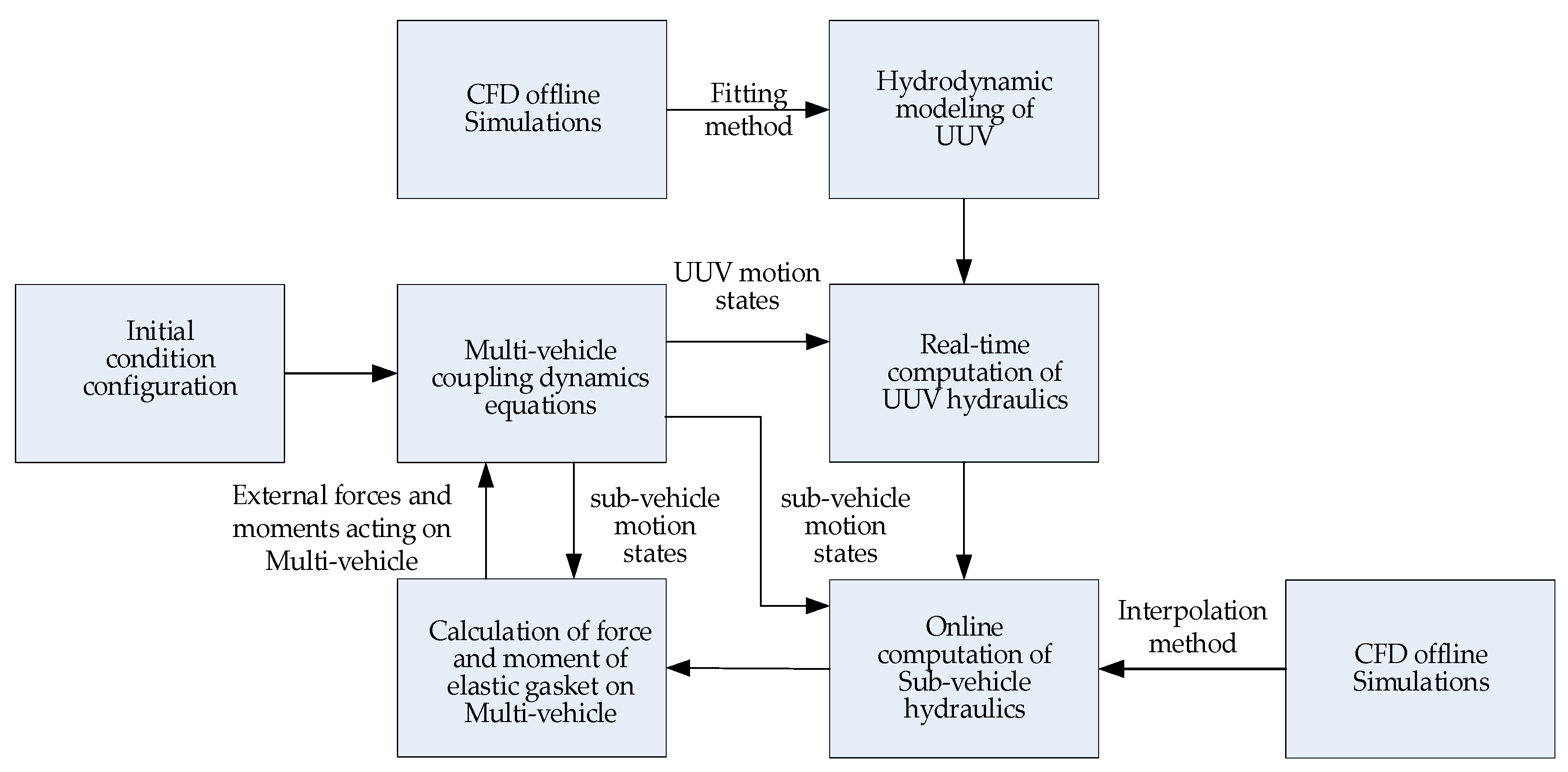
3. Hydrodynamic Modeling

3.1. Hydrodynamic Calculation Method of the Multi-Vehicle System

The hydrodynamic modeling method adopted in this paper is established based on Ref. [5], and the flow shape model of the UUV is appropriately improved to obtain better results. Therefore, this section only briefly describes the key equations and calculation results of the hydrodynamic modeling of the multi-vehicle.
Hydrodynamic calculation method of UUV:
The hydrodynamic calculation process for the UUV is as follows: First, a series of hydrodynamic data matrices under various angles of attack are obtained through CFD simulations. Subsequently, based on the least-squares method, approximate functional relationships between the angle of attack and the lift coefficient C L , drag coefficient C D , and pitch moment coefficient C M are fitted.
Using the aforementioned relationships, the lift, drag and pitching moment coefficients of UUV are obtained by the real-time angle of attack of UUV. The relationship between these coefficients and the corresponding lift L u , drag D u and moment M u is as shown in Equation (43) [22], where S u and l u represent hydrodynamic characteristic area and length, respectively.
L u = C L 1 2 ρ v 2 S u , D u = C D 1 2 ρ v 2 S u , M u = C M 1 2 ρ v 2 S u l u
The hydraulic force and moment of UUV defined by Equation (14) can be calculated according to Equation (44), where α u is the attack angle of UUV, and V u is the drainage volume of UUV.
F u , x w , B = D u cos α u + L u sin α u + ρ g V u sin η 1 F u , y w , B = D u sin α u + L u cos α u + ρ g V u cos η 1 M u w = M u
Hydrodynamic calculation method of sub-vehicle:
The hydrodynamic calculation method for the sub-vehicle is not entirely identical to that used for the UUV. The key difference lies in the fact that during the separation process of the sub-vehicle, the range of hydrodynamic forces acting on it constantly changes. Therefore, it is not feasible to use a single hydrodynamic coefficient. Instead, it is necessary to use pressure distribution data at different angles of attack for interpolation and to determine the range of the sub-vehicle entering the water in order to calculate the hydrodynamic force and moment.
The hydraulic force and moment of the sub-vehicle defined in Equation (16) can be calculated according to Equation (45) [5].
F s , x w , B = F s , x v , B + ρ g ( V 2 h 2 S 2 ) sin η 1 F s , y w , B = F s , y v , B + ρ g ( V 2 h 2 S 2 ) cos η 1 M s w = M s v ρ g ( V 2 h 2 S 2 ) δ r sin ( η 1 + η 2 )

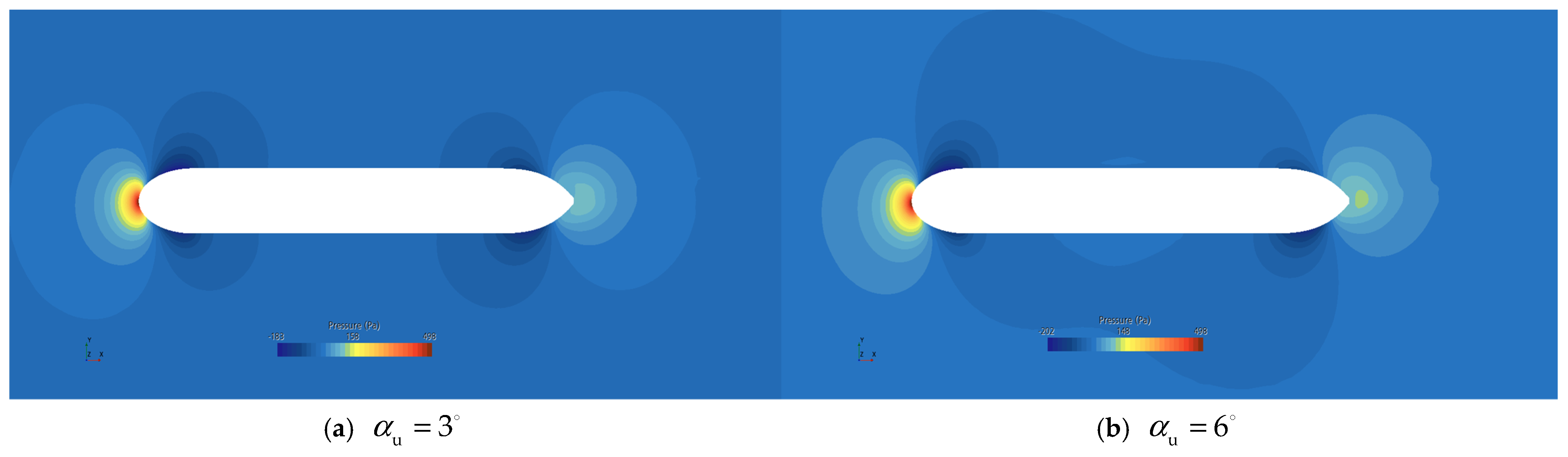
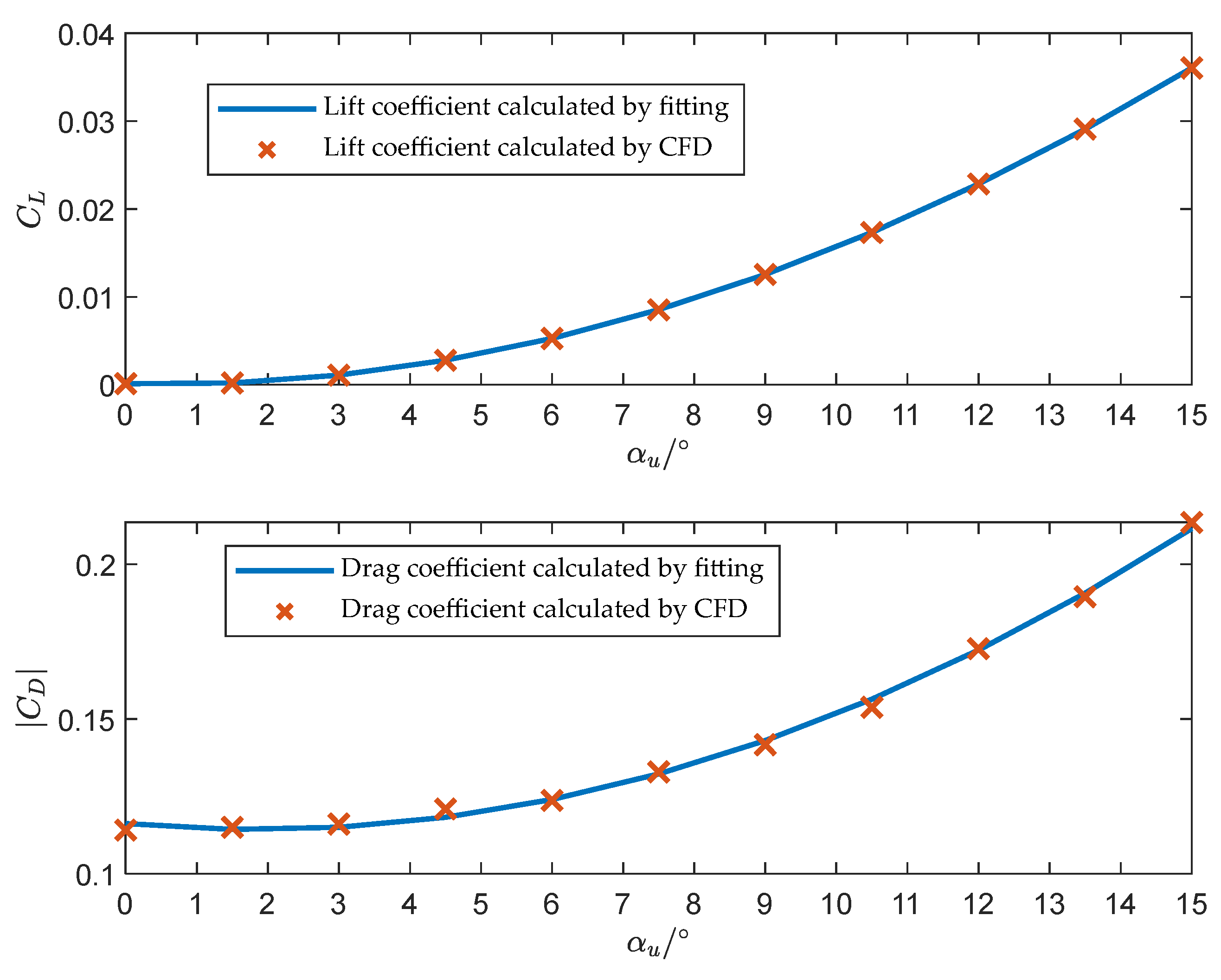
3.2. Improvement of UUV Geometry and CFD Simulation Results

The shape of the sub-vehicle utilized in this paper is consistent with that described in Ref. [5]. The geometric configuration of the UUV has been optimized for streamlining to minimize the likelihood of flow separation. The pressure distribution contour plots on the longitudinal plane of the UUV at various angles of attack are shown in Figure 3.
The variation curves of the UUV lift and drag coefficient with angle of attack calculated by fitting CFD data are shown in Figure 4. The variation curves of sub-vehicle lift and drag with angle of attack calculated by CFD data are shown in Figure 5. As observed in Figure 4, the curves obtained through the fitting method exhibit strong consistency with CFD data. The trend of variation conforms to the physical principles governing streamlined vehicles at small angles of attack, thus confirming the effectiveness of the hydrodynamic modeling approach proposed in this paper.

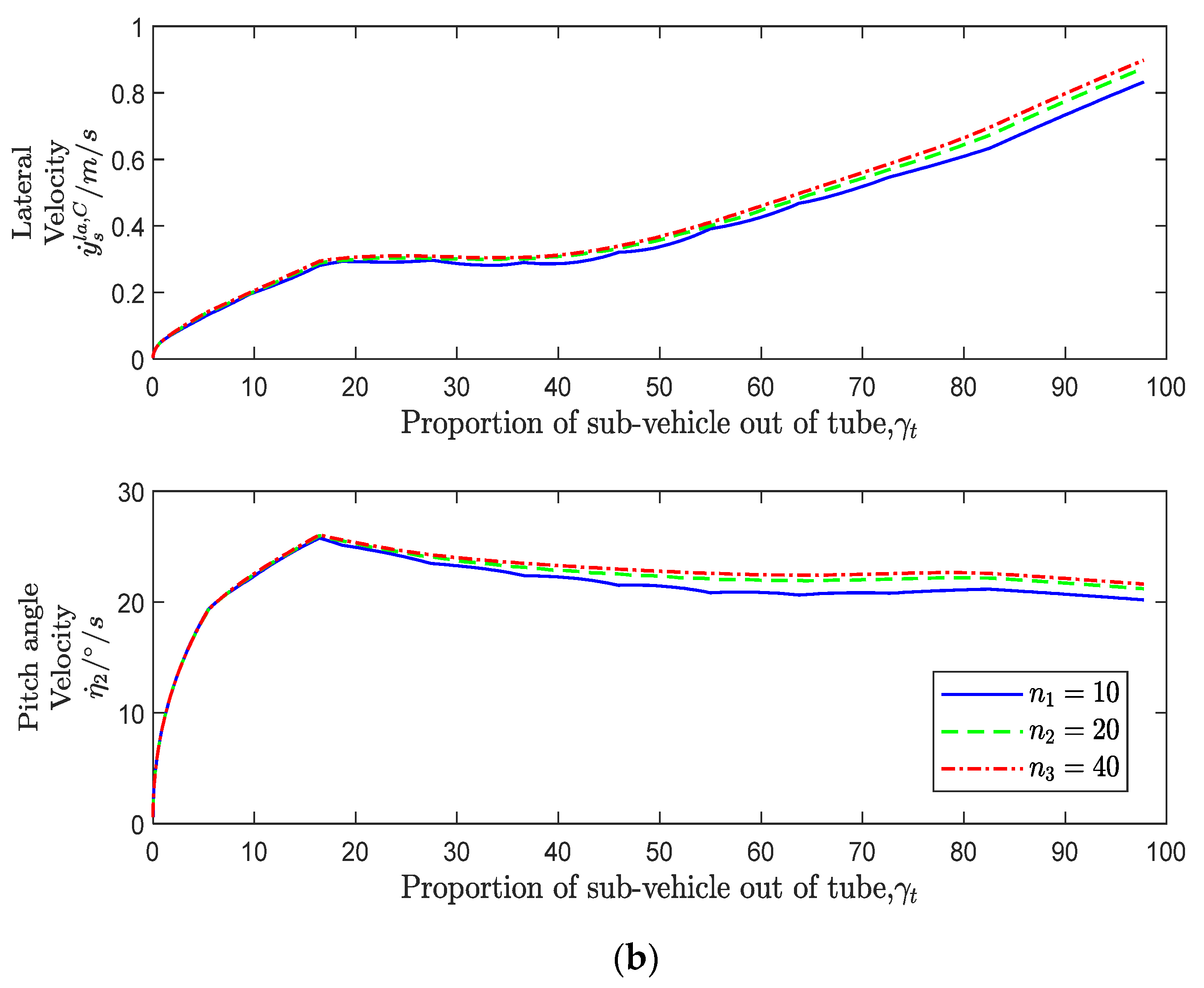
4. Simulation and Result Analysis of Multi-Vehicle Separation Process

4.1. Simulation Process Description

In this paper, the second-order differential equations of the multi-vehicle system dynamics, as given in Equation (36), are converted into a set of 12-dimensional first-order differential equations using the state space method and subsequently solved numerically with the fourth-order Runge–Kutta algorithm.
The primary purpose of installing elastic gaskets in the launch tube is to impose elastic constraints on the sub-vehicle, thereby mitigating the lateral loads encountered during separation while minimally impacting its pitch attitude. Therefore, it is particularly important to determine the appropriate stiffness and distribution for elastic gaskets. This study will focus on exploring the influence of the stiffness and distribution of the elastic gaskets installed in the launch tube on the motion and mechanical characteristics of the multi-vehicle system in the separation process. The product of the number of elastic gasket groups and the stiffness coefficient of the elastic gasket is defined as the total stiffness of the elastic gasket, expressed as K total .
Two simulation cases are established below:
(1)
The influence of elastic gasket stiffness variation on the motion and mechanical characteristics of the multi-vehicle system.
(2)
The influence of elastic gasket distribution variation on the motion and mechanical characteristics of multi-vehicle systems.
The separation process of the UUV and its sub-vehicle is numerically simulated in accordance with the principle block diagram, as shown in Figure 6.
The simulation process can be divided into three distinct stages, each characterized by specific dynamic behaviors and interactions among the multi-vehicle system. These stages are as follows:
Stage1: Constant-Speed Sailing
At this stage, the sub-vehicle is fixed with the UUV, and the system’s initial installation parameters are determined, providing initial conditions for the separation. The motion can be calculated using Equation (41).
Stage2: Two-Body Separation
The UUV provides launch thrust for a short time ( t h ) to the sub-vehicle, which then relies on inertia to leave the launch tube. The coupling dynamics characterized by the multi-vehicle at this stage can be solved using Equation (36).
Stage3: Post-separation Sailing
The purpose of this stage is to analyze the effects of the separation process disturbance on the UUV attitude. The dynamics equation for this stage is presented in Equation (42).
The three stages mentioned above are illustrated in Figure 7.
The multi-vehicle system model and initial motion parameters are listed in Table 2.

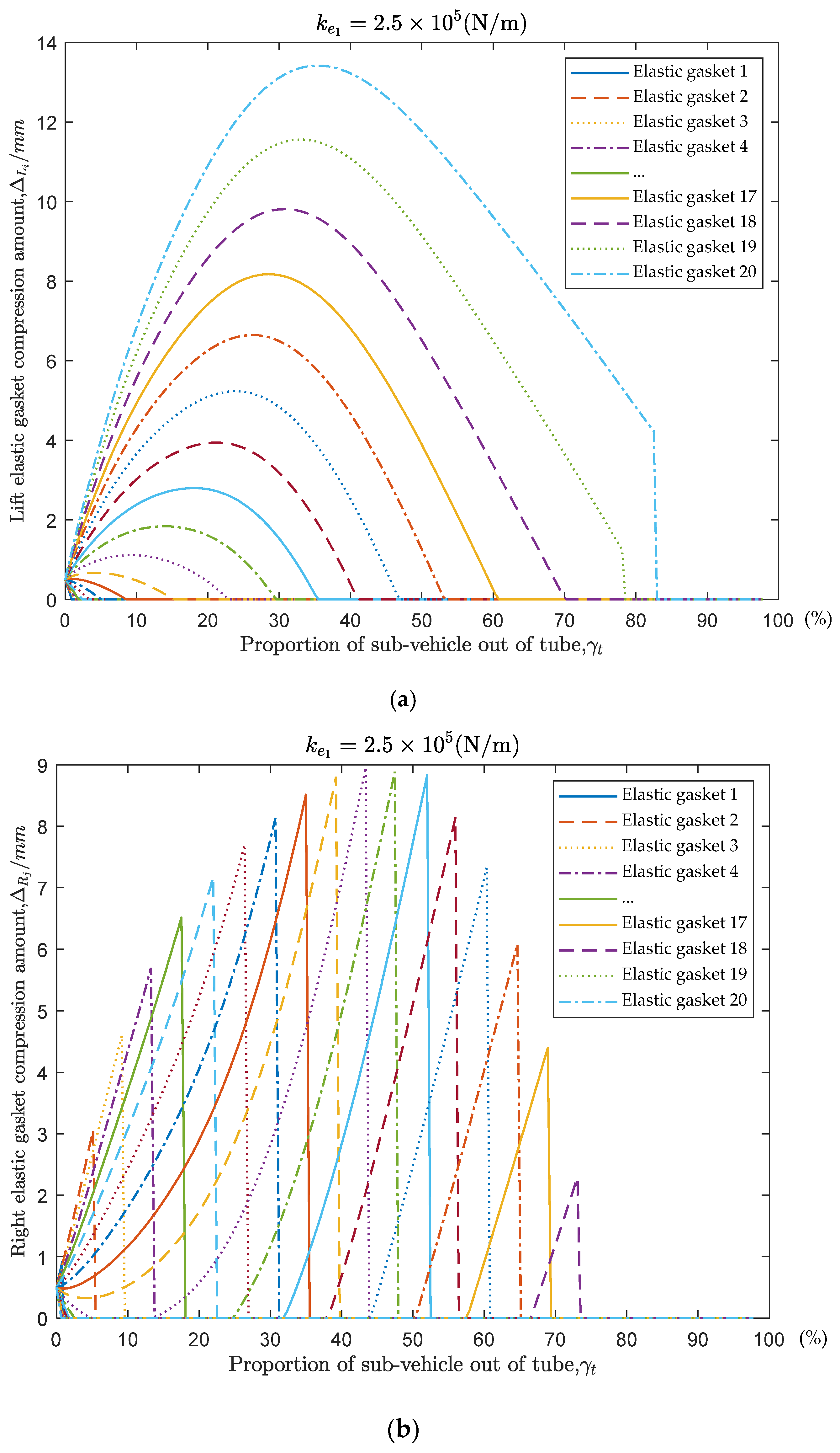
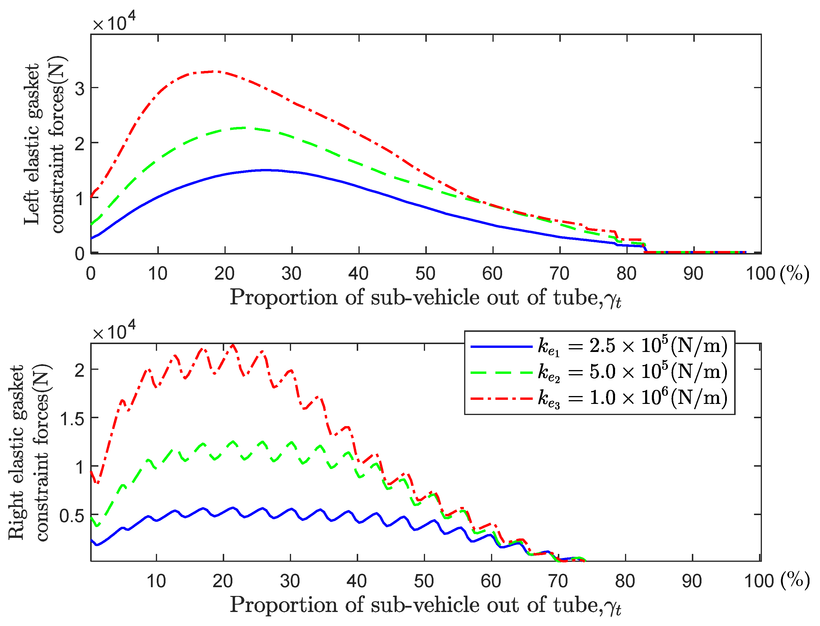
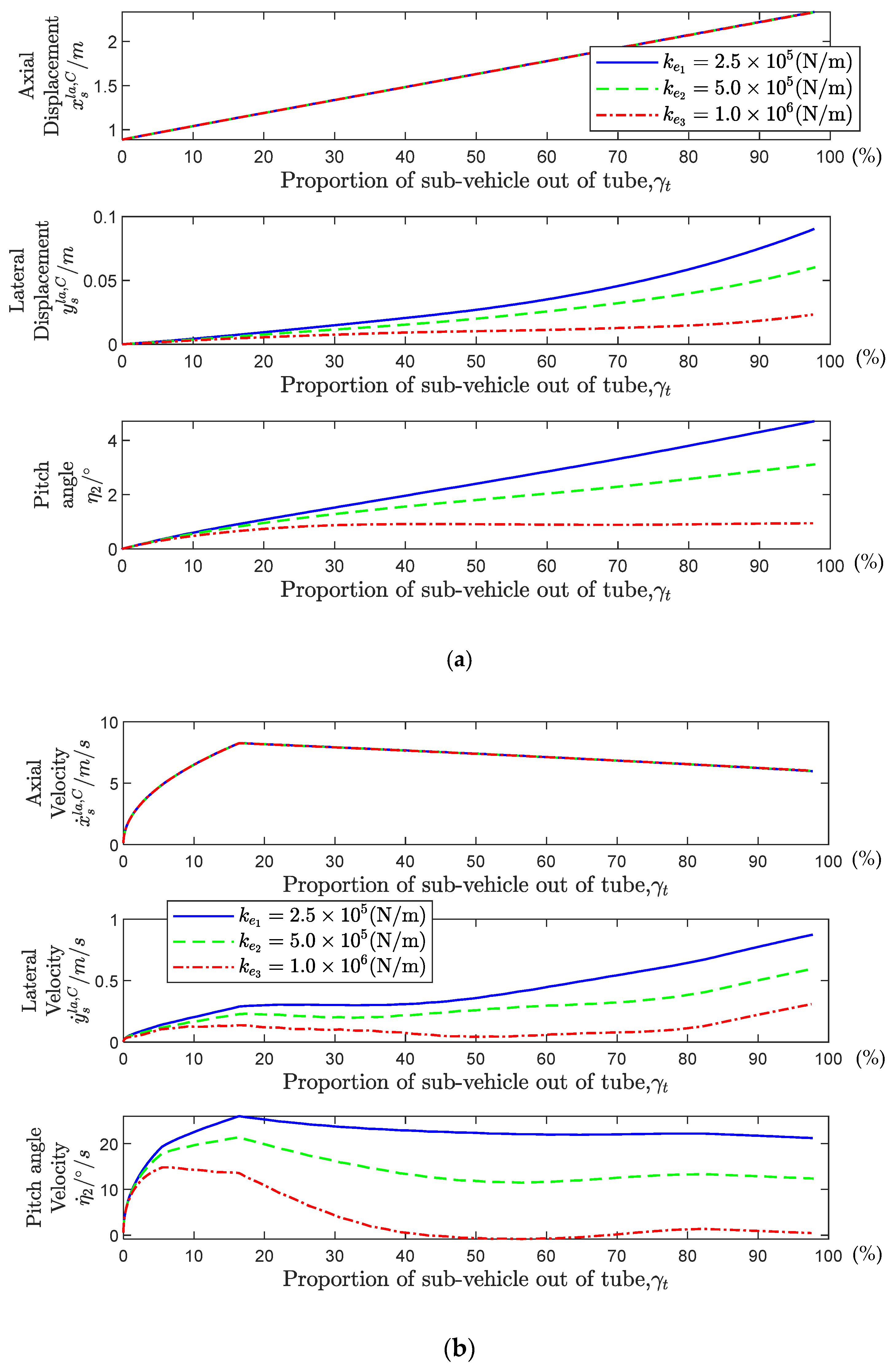
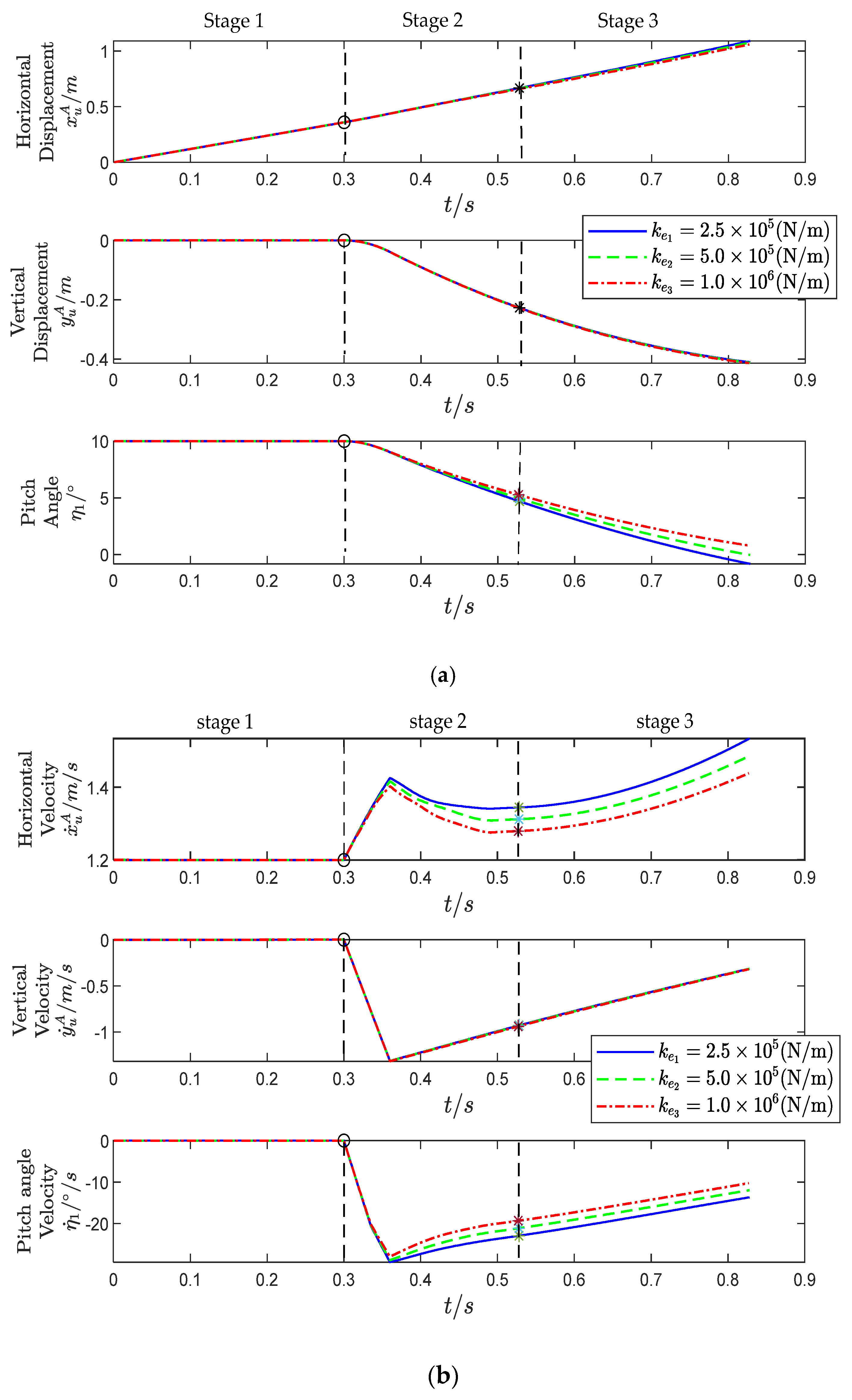
4.2. Influence of Elastic Gasket Stiffness on the Multi-Vehicle System

The first case examines the influence of elastic gasket stiffness on the motion and mechanical characteristics of the multi-vehicle system during the separation process. The number of elastic gaskets installed in the launch tube is set to 20, with their serial numbers increasing from bottom to top. The compression amounts of the left and right elastic gaskets are Δ L i , Δ R j ( i , j = 1 ~ 20 ) . The initial compression amount for all the elastic gaskets is 0.5 mm. This simulation is divided into three groups. In each group, the stiffness coefficients of all elastic gaskets are set to the same value. The stiffness coefficient values of three groups of simulated elastic gaskets are set as follows.
k e 1 = 2.5 × 10 5   N / m k e 2 = 5.0 × 10 5   N / m k e 3 = 1.0 × 10 6   N / m
Simulation results and analysis:
Figure 8 shows the variation in the compression amount of the left and right elastic gaskets during the separation process. The horizontal axis ( γ t ) indicates the relative displacement between the sub-vehicle and the launch tube. As shown in the figure, with the increase in relative displacement, the compression of both sides of the elastic gaskets exhibits a trend of first increasing and then decreasing. The difference lies in the fact that the compression amount variation of the left elastic gaskets is more continuous, and the maximum compression amount increases as the position approaches the top of the launch tube, while the compression amount curves of the right elastic gaskets change abruptly, with the maximum compression occurring in the middle. These differences are primarily determined by the force characteristics acting on the sub-vehicle during the process of leaving the launch tube.
Specifically, during the movement of the UUV to the right, the sub-vehicle experiences a hydrodynamic force to the left. The left elastic gaskets are continuously compressed due to the hydrodynamic force, with a greater compression amount near the top of the launch tube. Meanwhile, the right elastic gaskets provide a balancing moment only as the tail of the sub-vehicle passes by, resulting in a shorter compression amount. This leads to differences in the compression characteristics between the left and right elastic gaskets. As the length of the sub-vehicle exiting the launch tube increases, the elastic constraint gradually decreases, and the proportion of rigid-body motion due to hydrodynamic forces increases. Consequently, the proportion of the constraint force also decreases. Overall, the compression of the elastic gaskets initially increases and then decreases.
Additionally, it can be observed that for the elastic gaskets on the same side, the compression distribution characteristics are the same regardless of different stiffness levels. As the stiffness of the elastic gaskets increases, the compression amount decreases noticeably. This indicates that increased stiffness effectively reduces the lateral displacement and angular changes of the sub-vehicle, which is beneficial for controlling its attitude.
The constraint forces (elastic forces) provided by each elastic gasket on the left and right sides are summed individually, as shown in Figure 9. The curves of the constraint forces on both sides exhibited a characteristic of initially increasing and then decreasing, which is consistent with the variation in the compression amount of the elastic gaskets. The constraint forces on the right side show fluctuations, which corresponds to the sudden change in the compression amount of the right-side elastic gaskets.
A comparison of the constraint force curves for different stiffness values shows that as the stiffness of the elastic gaskets increases, the constraint forces acting on the surface of the sub-vehicle also increase significantly, which poses a potential threat to its structural safety. Conversely, selecting elastic gaskets with lower stiffness is found to significantly reduce the constraint forces, which proves advantageous for the structural design of the sub-vehicle.
Then, the influence of the stiffness variation on the pitching attitude of the sub-vehicle during the separation process is analyzed. As can be seen from Figure 10, an increase in the stiffness of the elastic gasket has a significant impact on the lateral and pitch motions of the sub-vehicle, which is manifested in the reduction of lateral displacement, pitch angle, lateral velocity and pitch angular velocity. However, the influence on the primary motion (axial motion) of the sub-vehicle is not obvious, as evidenced by the almost overlapping axial displacement and velocity parameters in Figure 10. It can be concluded that increasing the stiffness can effectively suppress the lateral motion of the sub-vehicle, preventing it from colliding with the UUV, which is beneficial for improving the safety of separation. Of course, the selection of the stiffness of the elastic gasket also needs to take into account the adverse effects of increased stiffness on the structural safety of the sub-vehicle.
Finally, the influence of the separation process and the variation in the stiffness of the elastic gaskets on the pitching attitude of the UUV is analyzed. Figure 11 shows the changes in the motion parameters of the UUV during three stages. It can be seen that the separation process has caused a significant disturbance to the motion of the UUV. Using elastic gaskets with higher stiffness can effectively suppress the pitching motion of the UUV. It is also found that, regardless of the stiffness of the elastic gaskets used, the UUV cannot spontaneously return to a Constant-Speed Sailing state after the separation process. Therefore, it is necessary to study the control of UUV after multi-vehicle system separation.

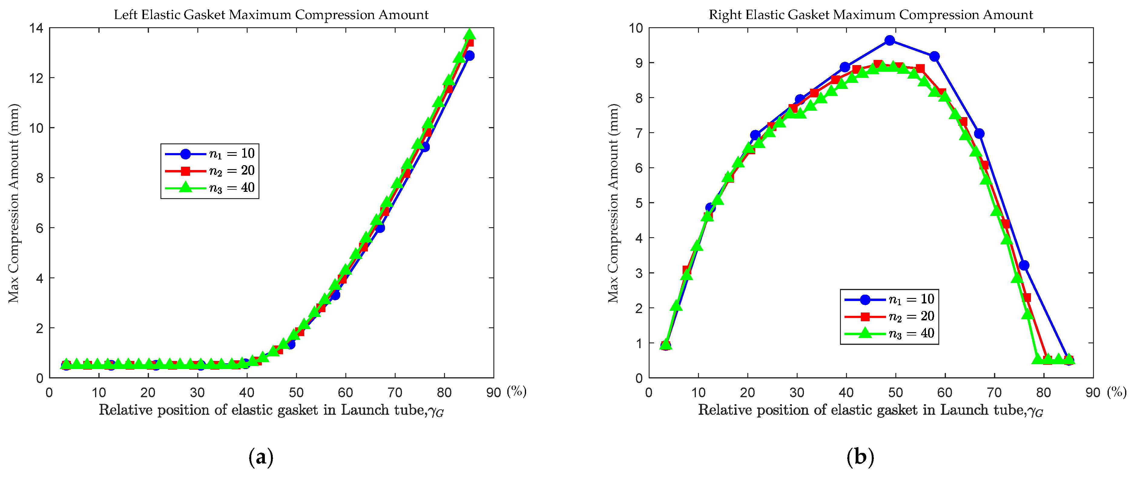
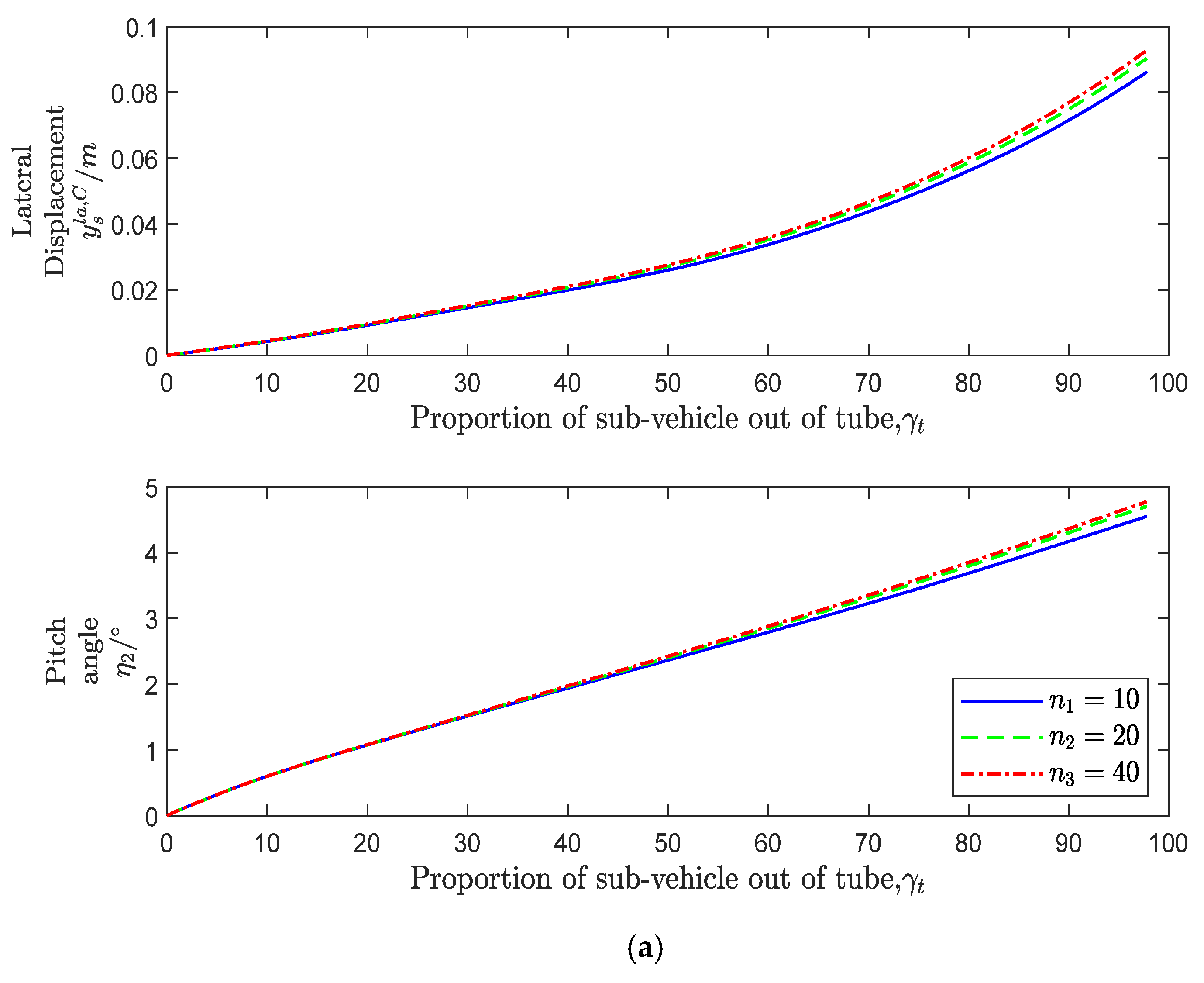
4.3. Influence of Elastic Gasket Distribution on the Multi-Vehicle System

The second case examines the influence of elastic gasket distribution variation on the motion and mechanical characteristics of the multi-vehicle system during the separation process.
The number and stiffness coefficients of the elastic gaskets are adjusted as follows to ensure that the total stiffness remains equal ( K total = 5 × 10 6   N / m ); the elastic gaskets are evenly distributed in these three cases.
n 1 = 10 , K e = 5 × 10 5   N / m n 2 = 20 , K e = 2.5 × 10 5   N / m n 3 = 40 , K e = 1.25 × 10 5   N / m
Simulation results and analysis:
Figure 12 shows the distribution of the maximum compression amount of the elastic gaskets under different installation schemes. The horizontal axis ( γ G ) indicates the relative position of the elastic gaskets inside the launch tube (the larger the γ G , the higher the installation position). As shown in this figure, the compression distribution patterns of the three schemes on the same side are identical. With the increase in the number of elastic gaskets, the peak compression on the left side slightly increases, while the peak compression on the right side decreases to some extent. However, the overall differences remain minimal. Table 3 presents the average values of the maximum compression of elastic gaskets in the bottom, middle and top regions of the launch tube. Based on the data, under the condition of identical total stiffness, the maximum average compression amount of elastic gaskets in the same region of the launch tube remains essentially consistent.
It can be observed that the distribution characteristics of the maximum compression amount of the elastic gaskets on different sides are distinct. The compression amount of the left-side gaskets increases as they approach the top of the tube, whereas the compression amount of the right-side gaskets initially increases and then decreases. These patterns are related to the force characteristics acting on the sub-vehicle. The maximum compression of each gasket does not occur at the same moment, but corresponds to the peak times shown in Figure 8.
The impact of the layout variation of the elastic gaskets on the motion of the sub-vehicle is also analyzed. Figure 13 shows the motion parameters with discernible changes. It is seen that with the increase in the number of elastic gaskets, the lateral displacement and pitch angle of the sub-vehicle, as well as the lateral velocity and pitch angular velocity, all increase slightly, but the increase is very small. Consistent with the conclusion analyzed above, when the total stiffness remained constant, the variation in the number of elastic gaskets had a small influence on the pitching attitude of the sub-vehicle.
The influence of the distribution variation of elastic gaskets on the load is also an important factor to pay attention to. As shown in Figure 14, when the total stiffness of the elastic gaskets remains consistent, the trend and magnitude of the constraint force provided by the left-side elastic gaskets are relatively close, while the differences in the curves on the right side are more significant. When the number of elastic gaskets decreases, the curves on the right side show obvious fluctuations, which are caused by the contact and detachment process between the right-side elastic gaskets and the tail of the sub-vehicle. These fluctuations are the same as those shown in Figure 8b, and impose additional vibration loads on the sub-vehicle, affecting structural safety. When the number of elastic gaskets increases, the contact and separation process becomes more continuous, and the curve fluctuations are significantly reduced. Therefore, when designing the layout scheme of the elastic gaskets, increasing their number appropriately and distributing them evenly can significantly improve the load environment of the sub-vehicle.

5. Conclusions

This paper has studied the problem of the safety assessment of underwater separation of multi-body systems with elastic constraints. Based on the Newton–Euler method, a multi-vehicle coupled dynamics model has been established, with a particular focus on constructing the elastic gaskets constraint model. Utilizing CFD data, the hydrodynamic model of the UUV has been developed through a fitting method, and the hydrodynamic model of the sub-vehicle has been established through an interpolation method. Building on these models, an FSI simulation method for the multi-body separation process has been developed, and the effects of variations in elastic constraint parameters on the motion and mechanical properties of the multi-vehicle system have been systematically investigated.
The following conclusions are drawn:
  • During the separation process, the pitching attitude of the sub-vehicle is negatively correlated with the variation in elastic constraint stiffness, while the load is positively correlated with it. This contradictory correlation posed challenges in parameter design.
  • When the total stiffness of the elastic gaskets remained constant, changes in the number of elastic gaskets had a minimal impact on the sub-vehicle’s motion state during separation, but significantly affected the load fluctuations on the sub-vehicle, leading to structural vibration issues.
  • The analysis method established in this paper is capable of quickly assessing the safety impact of different elastic gasket schemes on the separation of underwater vehicles and reveals the influence patterns of parameter changes on motion and load characteristics, thereby facilitating the optimization of design parameters.
The simulation results demonstrate that investigating the coupling dynamics of multi-body systems with elastic constraints is essential to ensure the navigation safety and structural safety of the multi-vehicle system. The multi-body dynamics model of UUV and the sub-vehicle established in this paper, along with the simulation conclusions derived, serve as valuable references for parameter design in engineering practice.
Further research efforts include the following: (1) Integrating the CFD hydrodynamic models of the UUV and sub-vehicle with their coupling multi-body dynamics model to establish a closed-loop simulation model, thereby enhancing the accuracy and reliability of simulation results. (2) Conducting physical experiments and performing comparative analyses with numerical simulation outcomes to refine numerical simulation techniques. (3) Exploring novel approaches for modeling multi-body coupling dynamics [23]. (4) Implementing active control on the UUV during the sub-vehicle separation process to stabilize its motion posture and improve navigational safety.

Author Contributions

Conceptualization, J.C.; Methodology, Y.H.; Resources, Z.H.; Writing—original draft, Y.H. and R.L.; Writing—review & editing, J.C. and Y.H.; Project administration, J.C.; Funding acquisition, Y.Z. All authors have read and agreed to the published version of the manuscript.

Funding

This research was funded by the National Natural Science Foundation of China, grant number 52272369.

Data Availability Statement

The original contributions presented in the study are included in the article, further inquiries can be directed to the corresponding author.

Conflicts of Interest

The authors declare no conflict of interest.

References

  1. Liu, Y.; Chen, L.; Su, Q.; Liu, C.; Lai, M. Research on the development and combat application of foreign underwater unmanned vehicle. Ship Sci. Technol. 2020, 42, 1–7. [Google Scholar]
  2. Zhang, X.; Hua, J. Study on the development and application of foreign extra-large unmanned underwater vehicles. Chin. J. Ship Res. 2024, 19, 17–27. [Google Scholar]
  3. Zhong, H. Review and Prospect of Equipment and Techniques for Unmanned Undersea Vehicle in Foreign Countries. J. Unmanned Undersea Syst. 2017, 25, 215–225. [Google Scholar]
  4. Chen, X. Study on Automatic Navigation System of Unmanned Underwater Vehicles. Master’s Thesis, Dalian Maritime University, Dalian, China, 2008. [Google Scholar]
  5. Chen, J.; Han, Y.; Li, R.; Zhang, Y.; He, Z. Coupling Dynamics Study on Multi-Body Separation Process of Underwater Vehicles. Drones 2024, 8, 533. [Google Scholar] [CrossRef]
  6. Han, Y.; Yin, W.; Zhang, Y. Aircraft-Rocket Coupling Dynamics for Gravity Air-Launch Without Launching Tube. J. Nanjing Univ. Aeronaut. Astronaut. 2022, 54, 311–320. [Google Scholar]
  7. Han, Y.; Yin, W.; Zhang, Y. Aircraft-Rocket Coupling Dynamics for Internally Carried Gravity Air-Launch Method. J. Nanjing Univ. Aeronaut. Astronaut. 2020, 52, 963–971. [Google Scholar]
  8. Wang, X.; Rui, X.; Yang, F.; Zhou, Q. Launch dynamics modeling and simulation of vehicular missile system. J. Guid. Control Dyn. 2018, 41, 1370–1379. [Google Scholar] [CrossRef]
  9. Zhang, D.; Wang, C.; Shen, Y.; Wei, Y.; Xu, H. Dynamic modeling and motion prediction of two projectiles launched successively underwater. Ocean Eng. 2024, 292, 116551. [Google Scholar] [CrossRef]
  10. Weiland, C.J.; Vlachos, P.P.; Yagla, J.J. Concept analysis and laboratory observations on a water piercing missile launcher. Ocean Eng. 2010, 37, 959–965. [Google Scholar] [CrossRef]
  11. Shang, S.-C.; Sun, J.-Z. Research on the Affection of the Underwater Missile Launching Process. In Proceedings of the 3rd International Conference on Mechanical and Electronics Engineering (ICMEE 2011), Hefei, China, 23–25 September 2011; pp. 2594–2599. [Google Scholar]
  12. Wang, Y.; Lin, T.; Jiang, H. Numerical analysis for water-exit trajectory of submarine-launched UUV. In Proceedings of the 2018 International Conference on Mathematics, Modelling, Simulation and Algorithms (MMSA 2018), Chengdu, China, 25–26 March 2018; pp. 276–279. [Google Scholar]
  13. Tan, D. Modeling and Simulation for Underwater Trajectory of the Submarine Horizontal Launched Vehicle on the Condition of Ignition Failure. J. Ordnance Equip. Eng. 2018, 39, 16–20. [Google Scholar]
  14. Cheng, Y.-S.; Liu, H. Mathematical modeling of fluid flows for underwater missile launch. J. Hydrodyn. 2006, 18, 481–486. [Google Scholar]
  15. Zhang, H.; Lu, H.; Pei, Y.; Ye, J.; Zou, Z. Numerical investigation to vertical launching of submarine launching missile. Chin. J. Hydrodyn. 2010, 25, 406–415. [Google Scholar]
  16. Wang, Z.; Gu, H.; Lang, J.; Xing, L. Safety Analysis of Initial Separation Phase for AUV Deployment of Mission Payloads. J. Mar. Sci. Eng. 2024, 12, 608. [Google Scholar] [CrossRef]
  17. Li, W.; Zhang, Z.; Lu, J.; Li, Z.; Wang, C. Investigations on the flow characteristics and the structural response of the launch tube during the underwater launching process. Ocean Eng. 2023, 279, 114603. [Google Scholar] [CrossRef]
  18. Lv, B.; Huang, B.; Peng, L. 21. Research on the uncertain factors to the control of submarine during missile launching process. Ship Sci. Technol. 2017, 39, 185–189, 193. [Google Scholar]
  19. Brito, M.; Canelas, R.B.; García-Feal, O.; Domínguez, J.M.; Crespo, A.J.C.; Ferreira, R.M.L.; Neves, M.G.; Teixeira, L. A Numerical Tool for Modelling Oscillating Wave Surge Converter with Nonlinear Mechanical Constraints. Renew. Energy 2020, 146, 2024–2043. [Google Scholar]
  20. Brito, M.; Bernardo, F.; Neves, M.G.; Neves, D.R.C.B.; Crespo, A.J.C.; Domínguez, J.M. Numerical Model of Constrained Wave Energy Hyperbaric Converter under Full-Scale Sea Wave Conditions. J. Mar. Sci. Eng. 2022, 10, 1489. [Google Scholar] [CrossRef]
  21. Li, J. Navigation Safety Analysis of Submarine after Underwater Vehicle Launching. Master’s Thesis, Harbin Engineering University, Harbin, China, 2022. [Google Scholar]
  22. Wu, W. Fluid Mechanics, 2nd ed.; Peking University Press: Beijing, China, 2021. [Google Scholar]
  23. Zhao, T.; Dai, J. Dynamics and coupling actuation of elastic underactuated manipulators. J. Robot. Syst. 2003, 20, 135–146. [Google Scholar]
Figure 1. Schematic diagram of the multi-vehicle system.
Jmse 13 00627 g001
Figure 2. Elastic gaskets configuration diagram inside the launch tube.
Jmse 13 00627 g002
Figure 3. UUV pressure contours at various attack angles on the longitudinal plane.
Jmse 13 00627 g003aJmse 13 00627 g003b
Figure 4. The hydrodynamic lift and drag coefficient curves of UUV.
Jmse 13 00627 g004
Figure 5. The hydrodynamic lift and drag curves of the sub-vehicle.
Jmse 13 00627 g005
Figure 6. Simulation principle block diagram.
Jmse 13 00627 g006
Figure 7. State diagram of the multi-vehicle in three stages.
Jmse 13 00627 g007
Figure 8. The variation curves of the compression amount of both sides of elastic gaskets. (Different elastic gasket stiffness coefficient) (a) Compression amount variation curve of the left elastic gasket. (b) Compression amount variation curve of the right elastic gasket.
Jmse 13 00627 g008
Figure 9. The combined elastic constraint force curves of the elastic gaskets on both sides (different elastic gasket stiffness coefficient).
Jmse 13 00627 g009
Figure 10. Motion parameters variation curves of the sub-vehicle (different elastic gasket stiffness coefficient). (a) Position motion parameter variation curves of sub-vehicle. (b) Velocity motion parameters variation curve of sub-vehicle.
Jmse 13 00627 g010
Figure 11. Motion parameter variation curves of the UUV (different elastic gasket stiffness coefficient). (a) Position motion parameters variation curves of UUV. (b) Velocity motion parameters variation curves of UUV.
Jmse 13 00627 g011
Figure 12. Max Compression amount curves of both sides’ elastic gaskets (different installation schemes of elastic gasket). (a) Maximum compression amount curves of left-side elastic gaskets. (b) Maximum compression amount curves of right-side elastic gaskets.
Jmse 13 00627 g012
Figure 13. The lateral and pitching motion variation curves of the sub-vehicle (different installation schemes of elastic gasket). (a) The variation curves of sub-vehicle lateral displacement and pitch angle. (b) The variation curves of sub-vehicle lateral velocity and pitch angle velocity.
Jmse 13 00627 g013aJmse 13 00627 g013b
Figure 14. The combined elastic constraint force curves of the elastic gaskets on both sides (different installation schemes of elastic gasket).
Jmse 13 00627 g014
Table 1. Model parameters of the multi-vehicle system and the meaning of the subscript.
Model ParametersMeaningsSuperscript and SubscriptMeanings
m u Mass of UUV A , B , C , D Corresponding coordinate system
m s Mass of sub-vehicle u , s , la UUV, sub-vehicle, launch tube
J u Pitch moment of inertia of UUV w Water
J s Pitch moment of inertia of sub-vehicle sb The bottom center of sub-vehicle
R la Radius of launch tube en Engine of UUV
R s Radius of sub-vehicle e Elastic gasket
ρ Water density
Table 2. Model and initial motion parameters of the multi-vehicle.
Model ParametersValueMotion State ParametersValue
m u / kg 5975 η 10 / ° 10
m s / kg 1195 x s 0 la , C / m 0.8866
J u / kg m 2 9497.4 y s 0 la , C / m 0
J s / kg m 2 2050 η 20 / ° 0
f / N 145,600 T 0 / N 40.42
t h / s 0.06 M u δ e 0 / N m 4470.44
Table 3. Maximum average amount compression of elastic gaskets at different positions in the launch tube (Different installation schemes of elastic gasket).
LocationNumber of Elastic GasketsThe Average Compression in the BottomThe Average Compression in the MiddleThe Average Compression in the Top
Left elastic gasket n 1 = 10 0.5 mm1.74 mm9.37 mm
n 2 = 20 0.5 mm1.92 mm9.46 mm
n 3 = 30 0.5 mm1.96 mm9.58 mm
Right elastic gasket n 1 = 10 4.23 mm9.23 mm3.56 mm
n 2 = 20 4.21 mm8.57 mm3.44 mm
n 3 = 30 4.21 mm8.54 mm3.42 mm
Disclaimer/Publisher’s Note: The statements, opinions and data contained in all publications are solely those of the individual author(s) and contributor(s) and not of MDPI and/or the editor(s). MDPI and/or the editor(s) disclaim responsibility for any injury to people or property resulting from any ideas, methods, instructions or products referred to in the content.

