Abstract
To achieve fast and stable scanning on lightweight shipborne electro-optical platforms, we propose a rotating dual-grating two-dimensional scanning system with inertial navigation feedforward and Fuzzy PID control. First, a two-dimensional scanning model using rotating dual grating with inertial navigation feedforward technology was proposed; in that system, the required positional information for the two gratings is determined based on the target location data. Then, the scanning model was combined with the Fuzzy PID algorithm to design a servo system controller that controls the dual gratings to perform beam deflection and scanning, then simulation. Finally, an experimental platform was built for validation. Under a sea-surface disturbance of 10° at 0.1 Hz, the scanning error of the entire process was controlled within 0.328 mrad (RMS) and the scanning of a 15° (half-angle) circular region was completed within 28 s. Compared with traditional control systems, significant improvements were achieved, with the scanning accuracy increased by more than 40.85% and the scanning speed improved by over 21.42%. This paper provides a reference for the application of a rotating dual grating electro-optical scanning platform on shipborne platforms.
1. Introduction
The modern maritime field has developed rapidly under the influence of multiple factors, including technological advancements, globalization demands, environmental protection, and geopolitics. Additionally, with militarization, its importance has been elevated, and countries are competing over maritime rights. Electro-optical tracking systems on shipborne platforms play a crucial role in spatial detection, collaboration, surface ship monitoring, and early-warning processes in maritime domains [1]. Traditional shipborne electro-optical tracking systems typically achieve beam pointing through multi-axis servo gimbals or optical mirrors to capture and track maritime targets. However, such systems have limitations, including large size, limited field of view, and weak anti-jamming performance, making them unsuitable for special application scenarios with restricted space or strict payload requirements [2]. More critically, the traditional PID control method exhibits significant limitations in shipborne dynamic environments: the fixed-parameter design is inadequate for addressing time-varying load characteristics caused by wave disturbances. Experimental results show that it produces an overshoot of 5–15% in step responses, and when the scanning speed increases to 0.4°/s, the RMS tracking error exceeds 600 μrad [3,4].
With the diversification of application demands, a rotating dual-grating electro-optical tracking and pointing device has emerged as a next-generation solution due to its compact structure and low rotational inertia. It achieves beam deflection by rotating two independent, coaxial, parallel gratings. In that way, it can enable efficient laser-beam scanning and beam pointing, as well as target acquisition and tracking tasks, demonstrating excellent scanning and acquisition performance [5]. In 2009, Kim’s team proposed “dual liquid crystal polarization gratings”. They deflected the beam and completed trajectory scanning within a specific angular range by controlling two independently rotating liquid crystal polarization gratings. This system not only has a high beam-transmission rate but also allows efficient beam pointing [6]. In 2013, Zhou, Y. et al. derived and verified the forward and reverse solution formulas for dual-prism beam pointing by using a non-axial ray-tracing method, discovering that the reverse calculation formula yields two sets of solutions [7,8]. In 2021, Qin, C. et al. achieved a back-and-forth spiral-scanning mode by controlling the synchronous rotation of the dual prisms. This mode showed excellent performance in terms of field-of-view coverage, periodicity, and speed stability. They optimized the scanning trajectory through integrated filtering and interpolation methods, which suppressed fluctuations in prism speed and reduced servo-control error from 1100″ to 350″ [9]. In 2024, Zhang, J. et al. designed a tracking model based on the decoupling of the optical axis and the reverse solution formulas of the dual liquid crystal polarization gratings. They combined it with Linear Quadratic Regulator (LQR) optimal control theory to test the tracking performance of this new electro-optical tracking system. The root mean square (RMS) value of the tracking accuracy was found to be less than 350 μrad [10].
However, existing rotating dual-grating control systems often employ predictive-control or adaptive-control model methods. The former relies on an accurate dynamic model (with modeling errors required to be within 5%), while the latter experiences a sharp decline in control accuracy when the parameters of the hydraulic actuator drift by more than ±20%. This creates a stark contradiction with the time-varying characteristics of mechanical parameters in shipborne environments (as the scanning speed varies nonlinearly with the scanning range and high-speed scanning may require rapid motor drives in the approach to the target). In contrast, Fuzzy PID control demonstrates unique advantages: it dynamically adjusts PID parameters via fuzzy inference, reducing overshoot without requiring an exact system model while significantly shortening the step response time [11].
To improve the scanning speed and stability of the dual-grating electro-optical tracking system on shipborne platforms, this paper designed a Fuzzy PID-based servo control system based on the dual-grating two-dimensional scanning model, combined with inertial navigation feedforward technology [12,13,14].
2. Related Works
In the 1990s, as part of the Strategic Defense Initiative (SDI), the United States began exploring laser communication between satellites and naval vessels. However, limitations in atmospheric-turbulence-compensation technology at the time constrained practical system performance. After 2000, advancements in adaptive optics enabled real-time correction of phase distortions caused by atmospheric turbulence, significantly improving the stability of laser communication. A notable milestone was achieved in 2001, when MIT Lincoln Laboratory successfully demonstrated laser communication between ships and aircraft. The first successful ship-to-ship laser communication was not realized until 2013, through experiments conducted by the U.S. Naval Research Laboratory (NRL). This breakthrough employed integrated high-precision gyroscopes and fast-steering mirrors to compensate for ship roll/pitch motions (±5° amplitude), achieving pointing accuracy below 20 μrad.
Currently, servo turntable scanning remains the predominant method for laser communication in shipborne electro-optical tracking systems. For instance, Chen, L. proposed a GPS-guided autonomous coarse tracking approach. This method transmits target location data provided by GPS to the coarse tracking system’s control computer via wireless networks. Subsequently, the system calculates the required rotational angles to precisely control the motor-driven turntable. This approach reduces coarse tracking latency and mitigates environmental interference [15]. Ma, J. introduced a dual time-varying boundary-layer sliding-mode control strategy for shipborne turntable position servo systems. Through the application of this control method, precise regulation of the turntable’s positional servo system is achieved [16]. Lin, Y. developed an intelligent shipborne electro-optical tracking system based on genetic algorithms and neural networks. The system employs nonlinear compensation to reduce complexity, enhance the learning efficiency of the neural network, and address convergence challenges arising from nonlinear noise in practical applications, enabling intelligent control [17].
All aforementioned shipborne electro-optical tracking systems employ servo turntables as actuators for the scanning process. Servo turntables exhibit drawbacks such as bulky dimensions, excessive weight, poor installation flexibility, significant mechanical inertia, slow response speeds (typically below 100 ms), and limited stabilization accuracy (approximately 0.03°). Consequently, researchers have begun replacing conventional servo turntables with compact devices such as rotating mirrors and Risley prisms for beam scanning, target acquisition, and tracking operations [18].
Based on our investigation, we found that documented applications of compact devices such as rotating mirrors and Risley prisms for beam scanning in shipborne electro-optical platforms remain scarce. Furthermore, their implementation on maritime platforms exhibits substantial limitations due to environmental constraints and dynamic operational requirements. Rotating mirrors offer wide scanning ranges but suffer from substantial mechanical inertia, low scanning frequencies (10–30 Hz), and susceptibility to hull-induced vibrations. Prism-based scanning demonstrates flexible scanning angles and superior vibration resistance compared to rotating mirrors, but it requires complex optical configurations and faces chromatic-dispersion issues.
3. Methodology
3.1. The Rotating Dual-Grating Two-Dimensional Scanning Model Based on Inertial Navigation Feedforward Technology
3.1.1. Model Derivation
The rotating dual-grating two-dimensional scanning model based on inertial navigation feedforward technology was built upon the spatial beam-pointing model of the rotating dual-grating and inertial navigation feedforward technology. It relies on diffraction to alter the direction of beam propagation, allowing the beam to perform stable scanning in a two-dimensional plane. When the ship is performing tasks on the sea surface, the change in the ship’s attitude causes the optical axis to jitter, which may result in target misalignment. Therefore, it is crucial to eliminate the effect of the change of the ship’s attitude. Feedforward compensation control combines deviation-correcting feedback loops with additional disturbance-anticipating feedforward paths, forming a composite control architecture. Direct measurement of the disturbance allows compensation to be applied before the disturbance causes an error, thus mitigating its impact in a timely manner [19,20]. The ship’s attitude angles, including pitch, roll, and yaw angles, need to be measured using an inertial navigation system installed on the ship’s deck [21]. First, the azimuth and elevation angles of the scanning trajectory (, ) are converted to their corresponding trajectory coordinates in the geodetic rectangular coordinate system (). These coordinates are then further converted to trajectory coordinates in the deck coordinate system (), resulting in a compensated trajectory that makes it possible to achieve stable two-dimensional beam scanning. Since the dual-grating platform and inertial navigation system are independently installed on the deck of the ship body, this paper simplifies the reference system as follows: the ship body frame and the platform frame share the same coordinate system, namely the deck coordinate system, while the navigation frame adopts the geodetic coordinate system. The rotating dual grating consists of a pair of parallel gratings that independently rotate around the coaxial Z-axis. They share the same rotation period, and through alteration of the rotation angles of the and gratings, the deflection angle Φ and azimuth angle Θ can be obtained to precisely adjust the beam pointing. The method of beam deflection is shown in Figure 1.
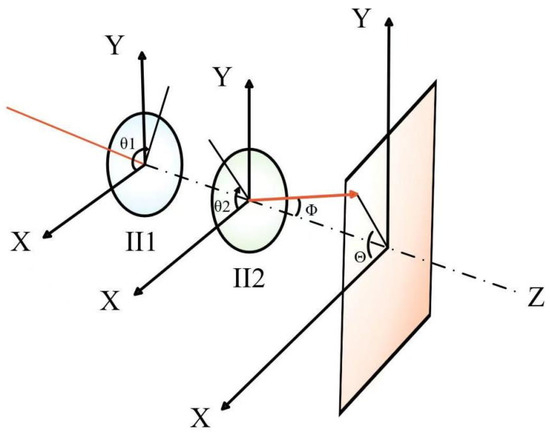
Figure 1.
Beam-deflection mode.
Based on the governing equations of the rotating dual grating, the spatial beam-pointing model of the rotating dual grating can be derived as in (1) and (2) [22], as follows:
In the equations, Φ represents the deflection angle of the emitted beam; Θ represents the azimuth angle of the emitted beam; is the wavelength of the incident light; is the grating period; and are the rotation angles of the two gratings, respectively. By optimizing the ratio of the rotation periods of the two gratings, an ideal two-dimensional scanning pattern can be established in certain planes perpendicular to the system’s optical axis. The Cartesian coordinates of the dual grating two-dimensional scanning pattern can be expressed as (3) and (4), as follows:
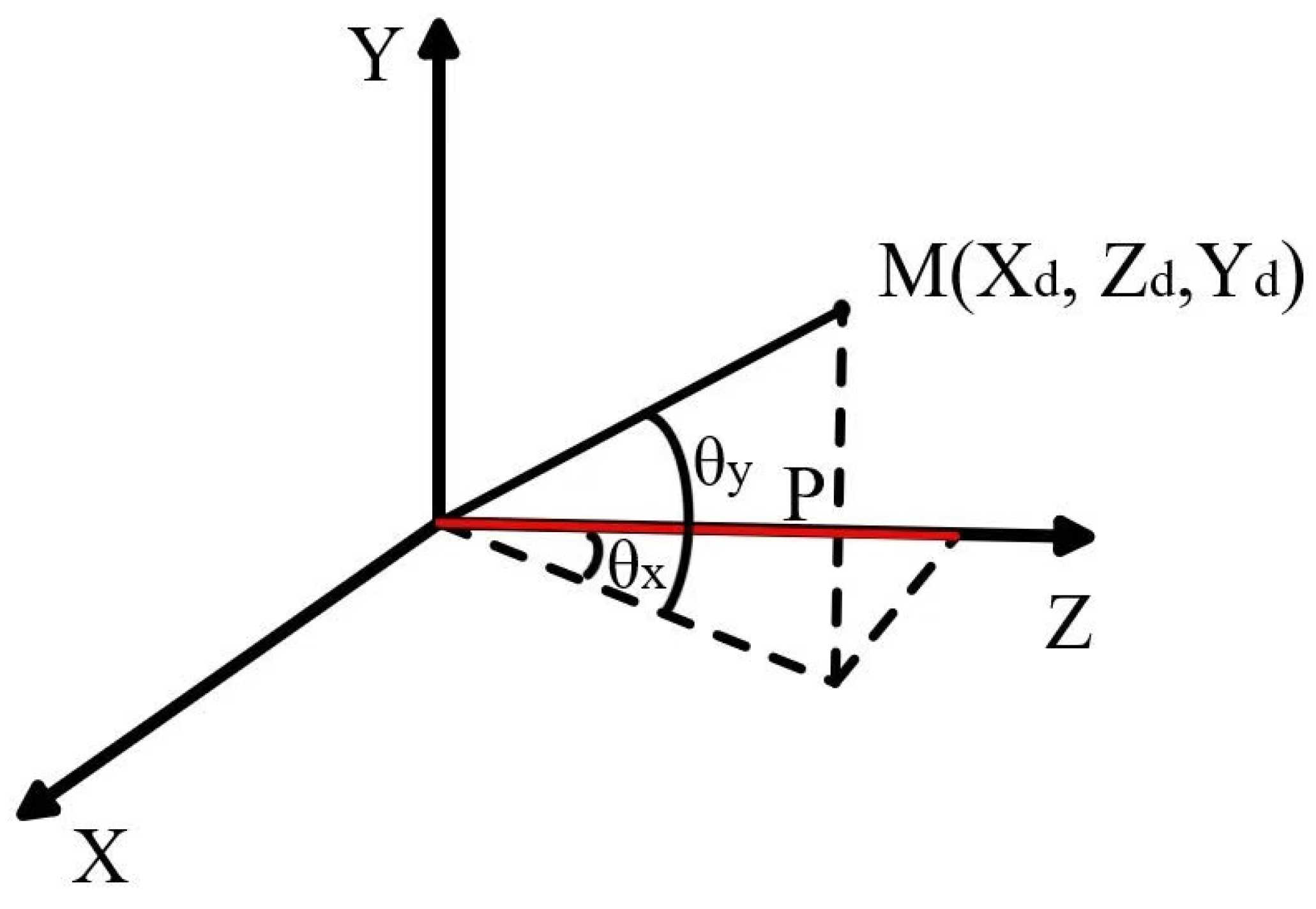
In the equation, P represents the distance from the second grating to the observation plane. As shown in Figure 2, consider a point M on a scanning trajectory perpendicular to the Z-axis in a geodetic rectangular coordinate system. The elevation angle () and azimuth angle () of point M correspond to its position coordinates ().

Figure 2.
Point M on the scan path is located in the geodetic coordinate system.
Equation (5) can be obtained from the geometric relationship in Figure 2, as follows:
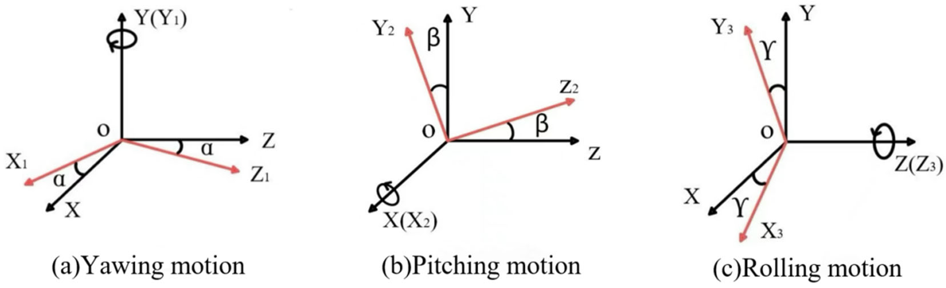
The ship’s posture variation is shown in Figure 3. The positive Z-axis aligns with the ship’s bow direction; the Y-axis is perpendicular to the ship’s deck; and the X-axis is orthogonal to the ship’s side.
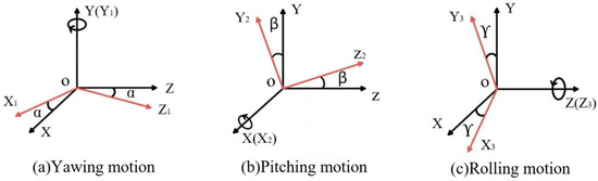
Figure 3.
Mode of ship attitude change with three degrees of freedom.
Let the yaw angle be α, the pitch angle be β, and the roll angle be γ; these represent the disturbances in the transformation from the local coordinate system of the ship to the geodetic rectangular coordinate system. When the three degrees of freedom of the ship’s posture occur simultaneously, the target position in the deck coordinate system () can be obtained by multiplying the ship’s posture-transformation matrix, as follows:
Since the roll motion is a rotation around the Z-axis, which coincides with the optical axis, and the observation plane is perpendicular to the Z-axis, the final Cartesian coordinates () of the compensated dual-grating observation plane are obtained as follows:
By substituting the compensated Cartesian coordinates of the dual-grating two-dimensional scanning pattern (7) and (8) into (1)–(5), the rotating dual-grating two-dimensional scanning model (9) and (10) can be established. At this point, the rotating dual-grating two-dimensional scanning model can not only correct the errors caused by the ship’s disturbance but also control the trajectory of the grating’s emitted beam to make it a straight line, thus enabling stable scanning of the beam in the two-dimensional plane.
3.1.2. Model Verification
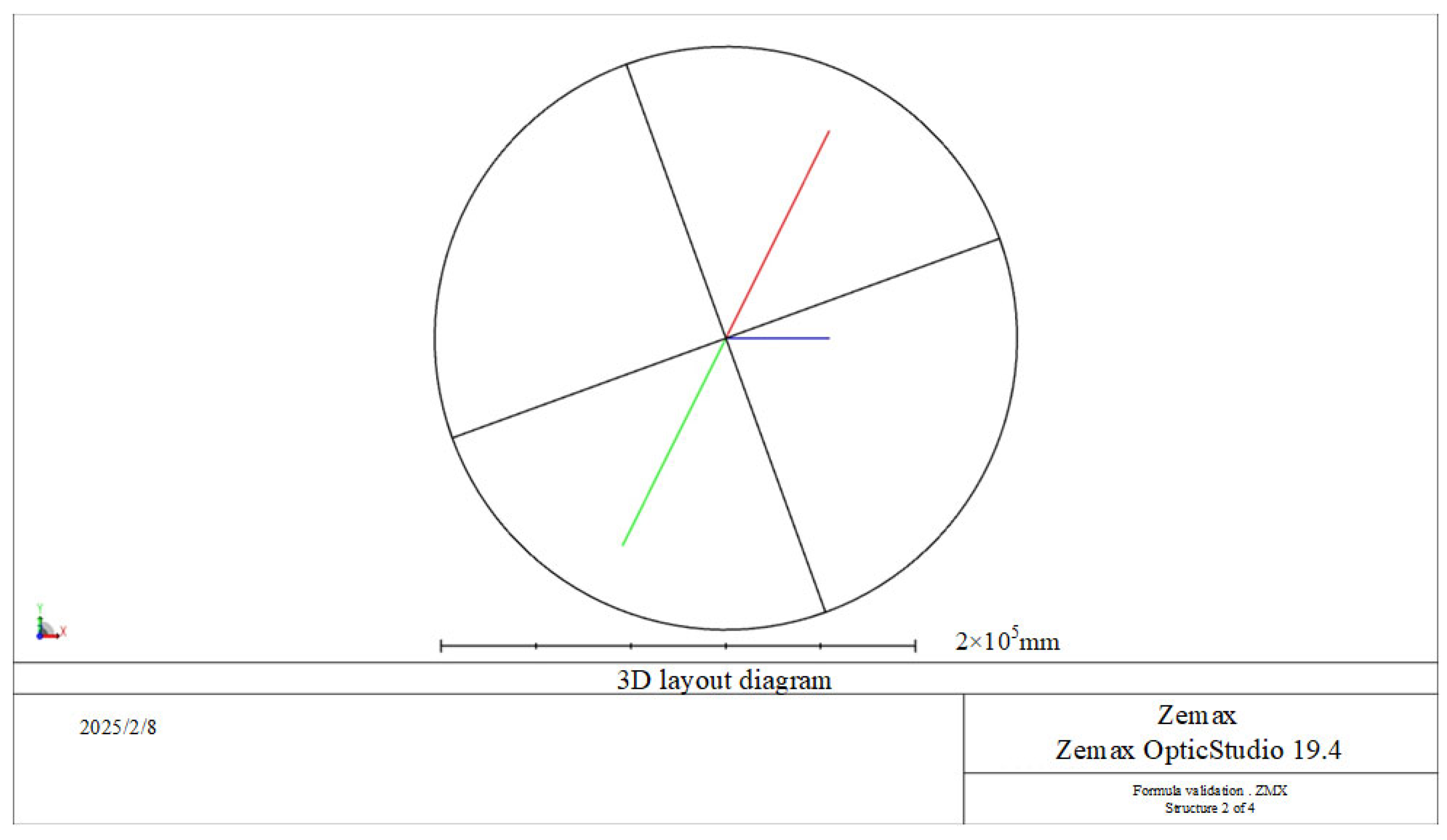
ZEMAX is a software program primarily used for optical design, simulation, and analysis. It is widely used by engineers and scientists to design, analyze, and optimize optical systems, such as lenses, mirrors, gratings, and other related optical components. ZEMAX offers various tools for ray tracing, system optimization, and tolerance analysis, allowing users to simulate the performance of optical systems under different conditions. We used ZEMAX (Version 19.4) to simulate the structure of a rotating dual-grating optical system to verify the applicability of the derived formulas [23]. The optical structure of rotating dual grating is shown in Figure 4, and its observed planar section is shown in Figure 5.
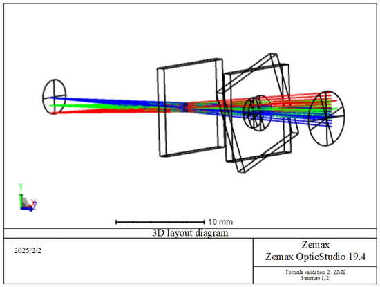
Figure 4.
Optical structure of rotating dual grating.
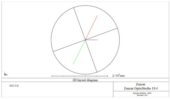
Figure 5.
Observed planar section.
The incident beam wavelength was set to 1064 nm, and the grating period was 7.322 μm. Rotating grating one and rotating grating two were placed with a common optical axis in parallel, as shown in Figure 4. The optical axis was viewed in reverse from the target position, with the grating lines aligned along the positive X-axis. The target position was uniquely determined in the rectangular coordinate system. The Z-axis was the common rotation axis of rotating grating one and rotating grating two, which was the system’s optical axis. The rotating dual grating could freely rotate in the range of (0°, 360°) in either the counterclockwise or clockwise direction. In ZEMAX, a multi-structure setup was used to rotate both gratings. The incident beam was directed toward the target along the positive Z-axis. In ZEMAX, the incident beam was introduced with an incident angle, which could represent the off-axis displacement. After diffraction by the two rotating gratings, which could rotate at different angles, the deflection angle and azimuth angle of the beam directed toward the target were obtained.
In ZEMAX, the incident azimuth and pitch angles were set, with the off-axis azimuth angle set to 0.1°. The pitch angle was varied from 0° to 180° in 20° increments. Rotating grating one was rotated counterclockwise by 0°, and rotating grating two was rotated counterclockwise by 20°. In the proposed formulas, α = 0°, β increased by 20° increments up to 180°, = 0°, and = 20°. The simulation results from ZEMAX tracing and substitution into the formulas yielded the data examples shown in Table 1.

Table 1.
Data table for incident azimuth angle 0.1° and incident pitch angle (0°~180°).
The calculated results demonstrated minimal discrepancies between our formula-derived target coordinates () and ZEMAX simulations, primarily due to mechanical and systemic errors. Although we could not simulate all possible values, we validated our approach by changing multiple sets of off-axis displacements and rotating dual grating rotation angles. Therefore, the usability of the proposed formula can be verified.
3.2. Design and Simulation of the Fuzzy PID Control System for the Rotating Dual-Grating Two-Dimensional Scanning Model Based on Inertial Navigation Feedforward Technology
3.2.1. Analysis of the Impact of Sea-Surface Disturbance
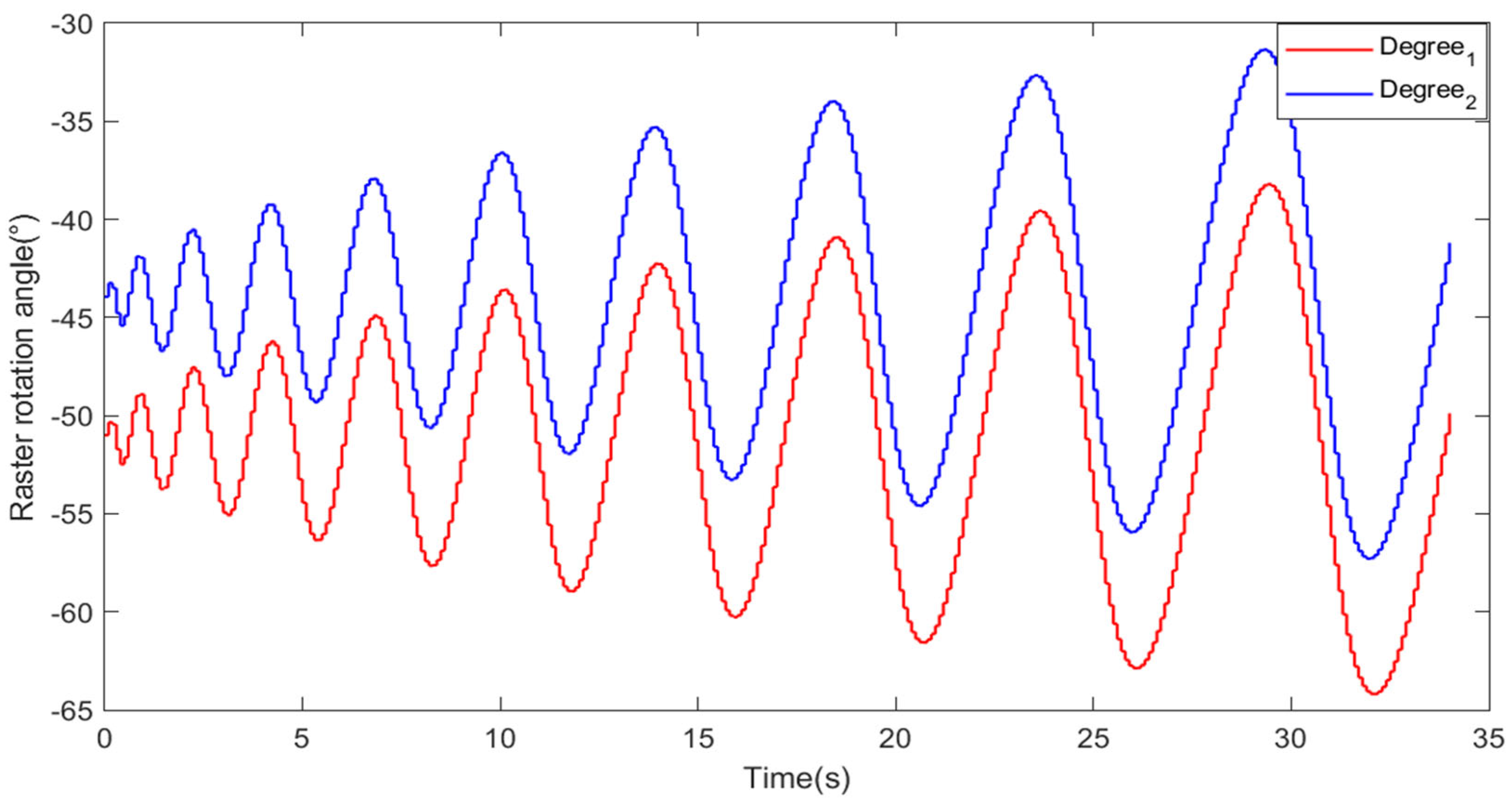
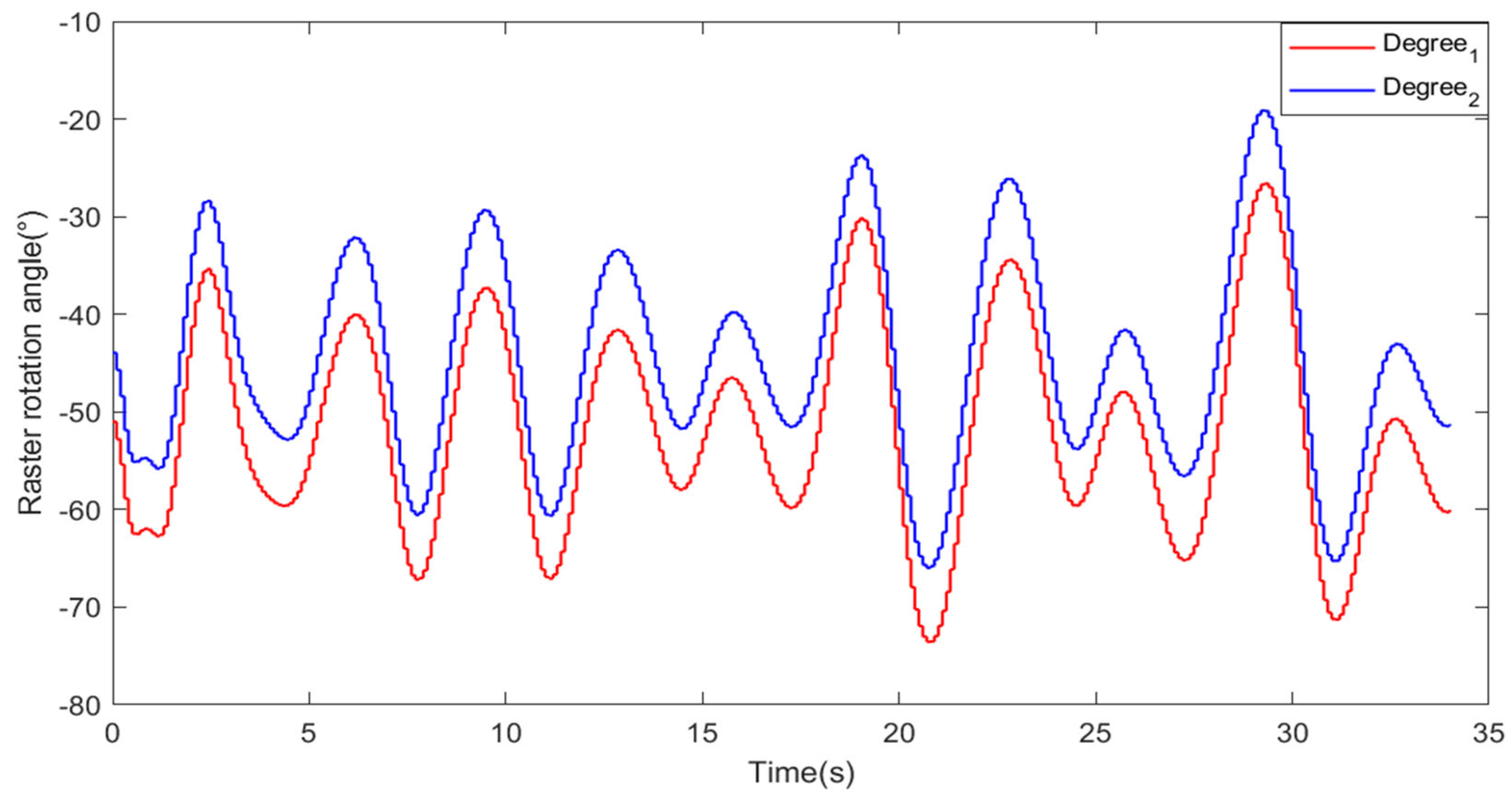
When a ship navigates on the sea surface, it encounters complex sea-state disturbances. According to available data, sea states are classified into levels ranging from 0 to 9. For an 180,000-ton bulk carrier, the rolling frequency at a sea state of level 5 is 0.1 Hz. According to the International Maritime Organization’s Convention on Standards of Training, Certification, and Watchkeeping (COLREGs), sea state level 5 is characterized by wind speeds of 17.2–20.7 m/s (33–40 knots), resulting in rough sea conditions that typically induce a ship attitude angle of approximately 10°. Therefore, a negative disturbance sine wave with an amplitude of 10° and a frequency of 0.1 Hz, opposite in sign to the ship attitude disturbance amplitude, was added at the input of the loop to simulate feedforward compensation. The trajectory of the grating’s rotation angle as a function of time before the negative disturbance was applied is shown in Figure 6, while the trajectory after the negative disturbance was applied is shown in Figure 7.
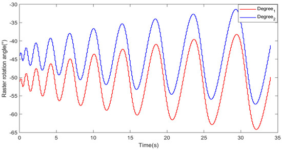
Figure 6.
Grating rotation trajectory before the addition of negative disturbance.
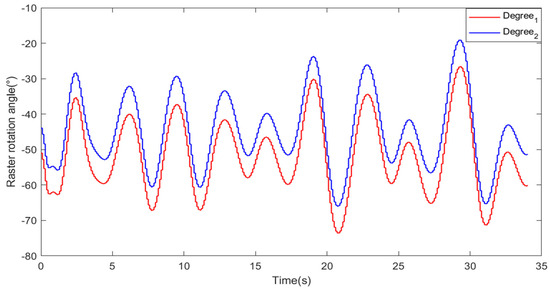
Figure 7.
Grating rotation trajectory after the addition of negative disturbance.
It can be observed that after the addition of the negative disturbance with feedforward compensation, the rotation trajectories of the two gratings exhibited irregular and complex changes. During actual scanning, the rotation speed of the dual gratings will experience abrupt changes when the rotation direction is altered, resulting in significant servo control errors. Therefore, it is necessary to design a novel control system to correct the servo control errors caused by the complex disturbances of the sea surface.
3.2.2. Design of the Fuzzy PID Control System for the Rotating Dual-Grating Two-Dimensional Scanning Model Based on Inertial Navigation Feedforward Technology
To achieve stable and rapid scanning of the rotating dual grating in the two-dimensional plane on the sea surface, a controller system combining a rotating dual-grating two-dimensional beam scanning model based on inertial navigation feedforward technology with Fuzzy PID control was designed. The Fuzzy PID can dynamically adjust the parameters of the PID controller based on real-time feedback from the system, thereby reducing overshoot and improving the response speed and accuracy of the scanning. Compared to traditional PID control algorithms, Fuzzy PID control enhances the system’s performance when it is faced with sea-surface disturbances and system variations, improving the system’s robustness. Furthermore, if the system exhibits uncertainty and nonlinearity, its control performance may degrade. Fuzzy PID control utilizes fuzzy logic processing to ensure that the dual grating system maintains stability and efficiency even under complex sea-surface conditions [24].
The system dynamics are described by differential equations, which were obtained by combining experimental methods with the derivation of the formula principles [25], as follows:
where v is the armature control voltage; L is the armature inductance; is the armature current; R is the armature resistance; is the back electromotive force constant; is the motor’s rotational angle; J is the motor’s moment of inertia; and is the damping coefficient. By applying the Laplace transform to both sides of the differential equations and eliminating intermediate variables, we derived the system’s transfer function, as follows:
Through the analysis of the electro-optical tracking system principles and the modeling of the controlled motor, we designed a Fuzzy PID control system for the rotating dual-grating two-dimensional scanning model based on inertial navigation feedforward technology.
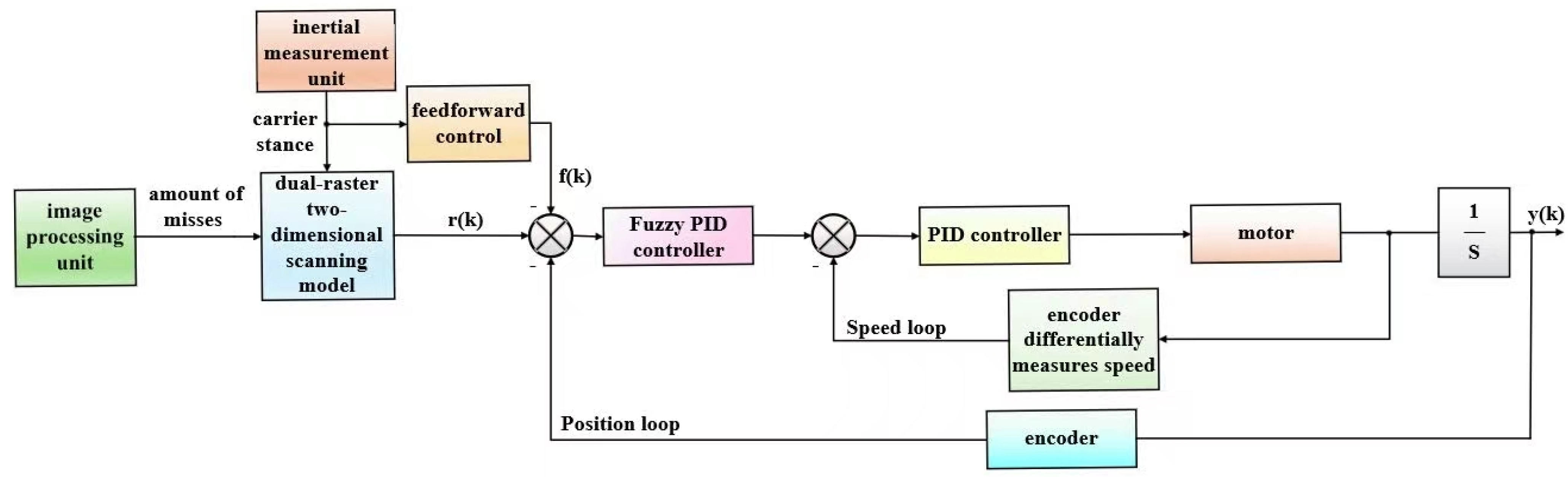
The control system block diagram is shown in Figure 8. The image-processing unit obtains the off-axis displacement information and calculates the azimuth and elevation angles of the scanning trajectory. The inertial measurement unit measures the platform’s posture information. The required rotation angles of the gratings are calculated using the rotating dual-grating two-dimensional scanning model. The desired position of the grating, r(k), is used as the target input. The position loop Fuzzy PID controller and the velocity loop PID controller process this input, with the position and rotational speed information of the grating being fed back to the position and velocity loops by the encoder, respectively. At the same time, the inertial navigation information f(k) is fed forward to the outer position loop. Finally, the control system completes the closed loop, and the output corresponds to the actual position y(k) achieved by the grating.

Figure 8.
Overall block diagram of the control system.
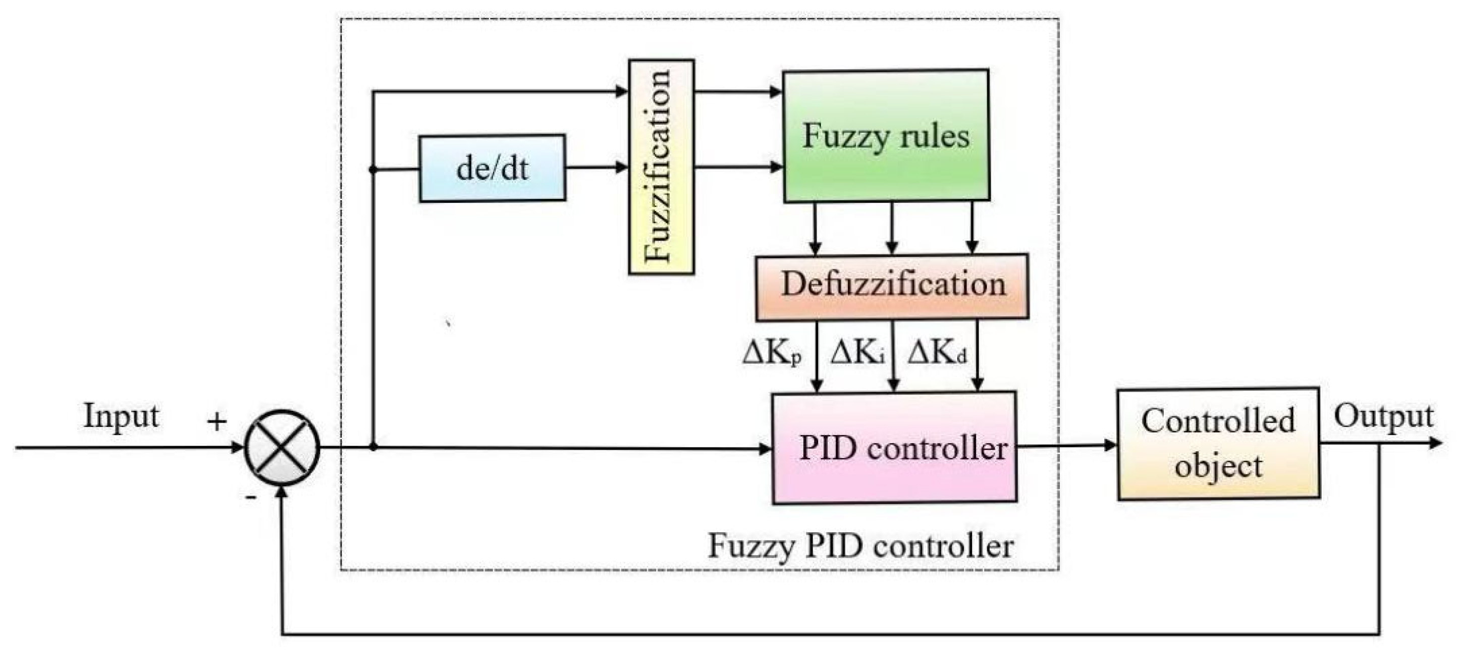
Figure 9 shows the block diagram of the Fuzzy PID controller.
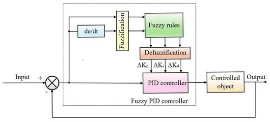
Figure 9.
Fuzzy PID controller structure block diagram.
The expression for the parameters of the Fuzzy PID controller is given by Equation (13), as follows:
The terms ,, and represent the initial values of the proportional, integral, and derivative components, respectively, while ,, and denote the adaptive variations of the proportional, integral, and derivative components. In this paper, the Mamdani fuzzy system is employed; this system addresses uncertainty and vagueness through four processes: fuzzification, rule evaluation, inference calculation, and defuzzification. The Mamdani fuzzy system quantifies uncertainty using membership functions, effectively handling real-world issues such as sensor noise and ambiguous linguistic descriptions. Experimental results indicate that even with a noise intensity of 20%, the Mamdani system maintains a control accuracy of over 92%.
First, the input was fuzzified and the two inputs of the fuzzy controller, e and ec, were quantized using a quantization function, mapping them to a real value within the fuzzy domain. Here, e and ec, respectively, represent the difference between the actual and desired rotational angles of the rotating dual grating and its rate of change over time. Fuzzy subsets and membership functions were selected, and the membership degrees of the real values belonging to each subset were calculated, transforming the original precise quantities into fuzzy values, which were then represented by the corresponding fuzzy sets. When the number of linguistic variables in the fuzzy subsets is small, the control rules become coarse, leading to poor control performance. When the number of linguistic variables in the fuzzy subsets is large, control performance improves, but the control rules become more complex. In this study, the number of linguistic variables was set to five, which balances the precision and stability of the rotating dual grating electro-optical tracking system. The fuzzy subsets for the inputs and outputs were defined as {NB, NS, ZO, PS, PB}. The triangular membership function, which exhibits high sensitivity and can promptly respond to changes in the input, was selected because it allows the system to better handle external disturbances. Meanwhile, considering microcontroller limitations, straight-line mathematical descriptions are computationally simpler than curves. Thus, a triangular membership function was chosen in this paper.
Next, fuzzy rules were designed and fuzzy inference was performed based on these rules to derive the fuzzy output. The fuzzy control rules are the core of the Fuzzy PID controller and were derived from expert experience [26]. According to the functions , , , the fuzzy control rules were designed as follows. In cases of large values of , to ensure fast response by the system, a larger should be chosen. To prevent differential overflow caused by the sudden increase in the error at the beginning, a smaller should be chosen, and to avoid excessive error accumulation, a smaller should be chosen. When is moderate, to reduce overshoot while ensuring a certain response speed, should be appropriately reduced. Under these conditions, the system is more affected, so should be smaller and should be set to a moderate value. When is small, larger values of and should be selected to ensure the steady-state performance of the system. Additionally, to enhance the system’s anti-interference capability, when is large, a smaller should be chosen, and when is small, a larger can be chosen. Based on these considerations, the fuzzy control rules for ,, are shown in Table 2, Table 3 and Table 4 below. These designed control rules ensure that the rotating dual-grating electro-optical tracking system can quickly eliminate large errors and maintain system stability when the errors are small.
Table 2.
Control-rule table for .
Table 3.
Control-rule table for .
Table 4.
Control-rule table for .
The final clear values of ,, and were obtained through defuzzification. In this paper, the centroid method was used for defuzzification, and its expression is given by Equation (14), as follows:
In the equation, represents the fuzzy variable element and denotes the membership degree of .
3.2.3. Simulation Verification
During the scanning process, response speed is a critical factor in improving scanning speed. To validate the effectiveness of the controller designed in this paper, simulations of the response speed were first conducted in Simulink using traditional PID and Fuzzy PID controllers. A 1° step input signal was applied, and the output responses of the two controllers were compared. As shown in Figure 10, when the PID control algorithm was used in the position loop controller, the steady-state time of the output response was 0.25 s, with an overshoot of 9.5%. When the Fuzzy PID control algorithm was used in the position loop controller, the steady-state time of the output response was 0.07 s, with almost no overshoot. Comparing these results, it was found that the response speed was improved by 25.7% when the Fuzzy PID control algorithm was used. Therefore, it can be concluded that this algorithm has better dynamic performance and can enhance the response speed.
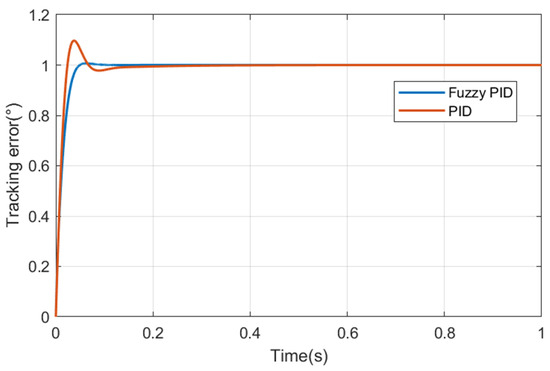
Figure 10.
Step response.
3.3. Experimental Design
To verify the scanning performance of the rotating dual-grating electro-optical tracking system, a scanning experiment was conducted using the electro-optical platform shown in Figure 11. Beam deflection was achieved through the diffraction characteristics of the dual gratings. The two gratings were coaxially aligned and independently placed, with a servo motor driving the dual gratings to rotate. The encoder displayed the motor’s angular position as the feedback signal for the control system. After the incident beam passed through the dual-grating system, it underwent beam deflection, with the deflection angle calculated using the forward and reverse solution models. The emitted beam was then focused by an off-axis optical antenna and received by a camera. The image processing unit processed the image data from the camera to determine the target off-axis displacement. The inertial measurement unit was mounted on the platform to provide feedback on the platform’s position, attitude, and other information. The servo control system selected the STM32F407 microcontroller (Zerong Technology Co., Ltd., Shenzhen, China) as the motion-control master unit (based on the ARM Cortex-M4 core; with a clock frequency of 168 MHz; flash memory of 1 MB; RAM of 192 KB; voltage range of 1.8–3.6 V; ADC/DAC configuration included 3 × 12 bit ADCs (24 channels, 2.4 MSPS)/2 × 12 bit DACs; timer configuration included 14 timers (including twi advanced control timers supporting PWM)). The motor (Aifurui Mechanical Transmission Equipment Co., Ltd., Tianjin, China) selection and parameters are shown in Table 5. The encoder (Changguang Qiheng Sensing Technology Co., Ltd., Changchun, China) selection and parameters are shown in Table 6. The system had a sampling frequency of 1000 Hz, and the camera operated at a frame rate of 100 frame/s with an angular resolution of 15.625 μrad. The lifting platform was employed to achieve optical axis alignment, while the swing table (Ruixin Technology Co., Ltd., Suzhou, China) was utilized to simulate sea surface disturbances. The model was created using the C programming language on the Microsoft Windows 10 64 bit operating system for software development. The calibration of experimental instruments (including zero calibration, span calibration, and multi-point calibration) was performed through the recording and analysis of experimental data to maintain the credibility of experimental results.
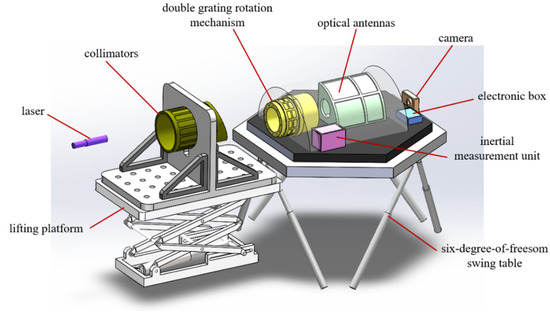
Figure 11.
Model of the experimental system.
Table 5.
Main parameters of motors.
Table 6.
Encoder parameters.
To validate the effectiveness of the Fuzzy PID control system for the rotating dual-grating two-dimensional scanning model based on inertial navigation feedforward technology, a comparison was made with the traditional dual-loop control system that does not incorporate inertial navigation feedforward technology and uses the PID control algorithm. Setting up the rotating dual-grating experimental platform allowed a spiral trajectory scan to be performed, and the actual scanned trajectory data were collected. The data were then compared with the desired trajectory data obtained from the calculation module, resulting in the scanning error curve.
4. Results & Discussion
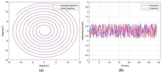
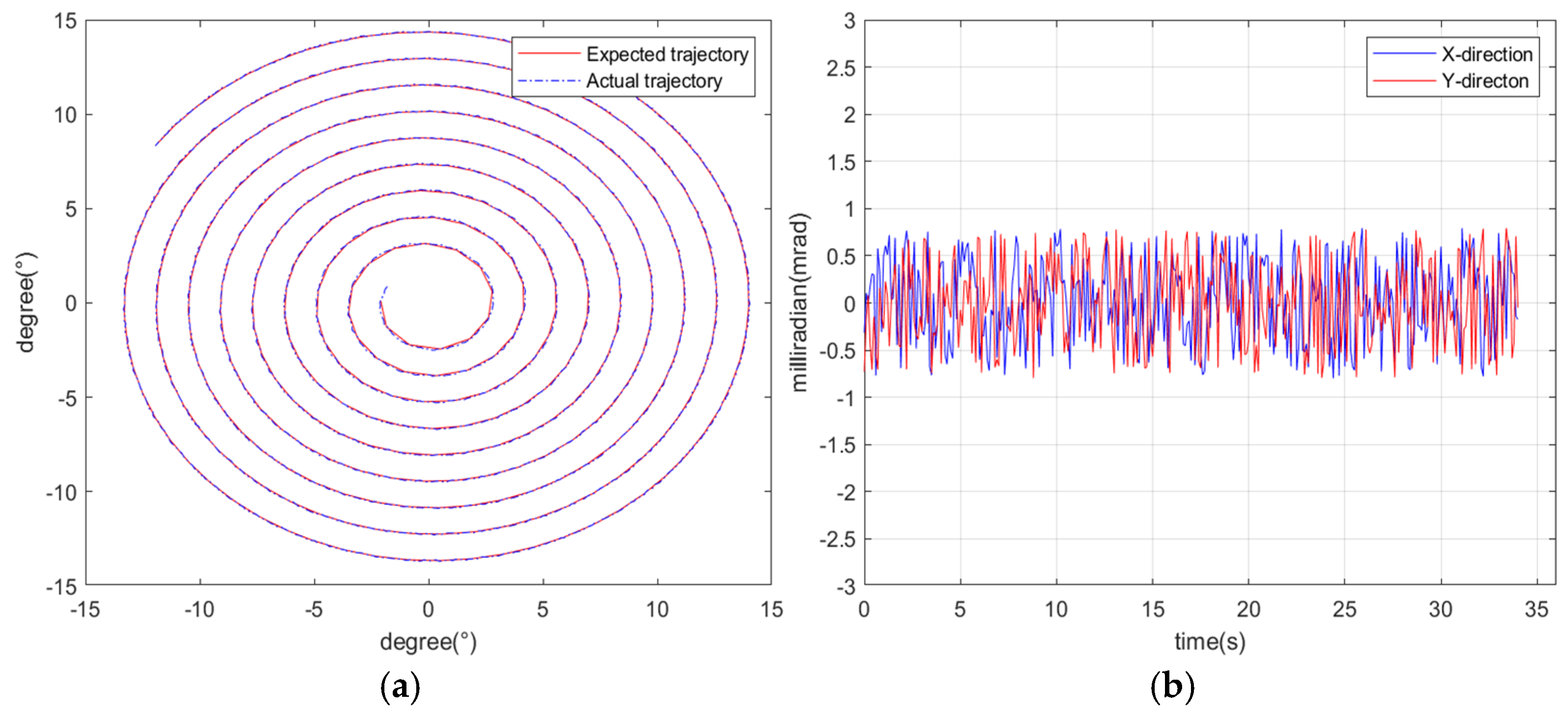
Figure 12.
Scanning trajectory of the old control system’s experimental platform: (a) scanning trajectory; (b) scanning error in the X and Y directions (approximately 0.8 mrad).
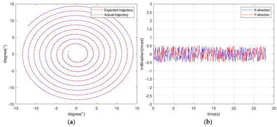
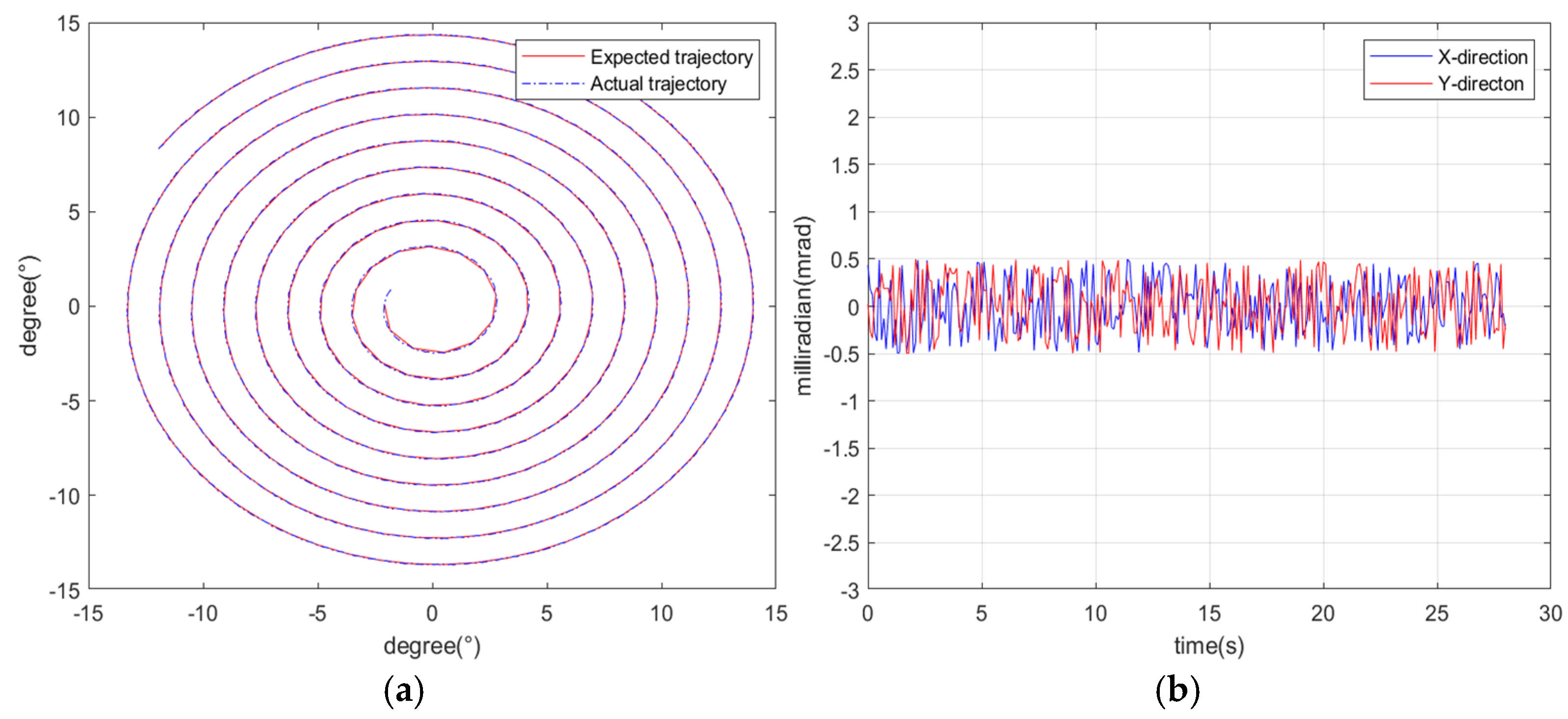
Figure 13.
Scanning trajectory of the new control system’s experimental platform: (a) scanning trajectory; (b) scanning error in the X and Y directions (approximately 0.5 mrad).
The scanning range was a circular area with a half angle of 15°. The experimental results show that under the disturbance of a maximum ship attitude angle of 10° and a frequency of 0.1 Hz, the maximum scanning error of the traditional control system was approximately 0.8 mrad. During the entire scanning process, the scanning error was controlled within 0.462 mrad (RMS) and the full circular field of view was scanned within 34 s. In contrast, the maximum scanning error of the designed control system was 0.5 mrad and the scanning error was controlled within 0.328 mrad (RMS) throughout the scanning process, with the full circular field of view being scanned within 28 s. It can be concluded that the Fuzzy PID control system for the rotating dual-grating two-dimensional scanning model based on inertial navigation feedforward technology has greater scanning accuracy and faster scanning speed compared to the traditional dual-loop control system, validating the effectiveness of the designed system.
In this experiment, the combined application of inertial navigation feedforward technique and Fuzzy PID control algorithm significantly mitigated servo control errors induced by hull disturbances. However, residual error sources persisted in the results, with these errors including but not limited to the following: CCD sensor detection inaccuracies, boresight alignment deviations, mean square errors caused by mechanical backlash-induced random oscillations, signal-processing latency errors, stiction-induced hysteresis, and temporal-synchronization discrepancies—all potentially contributing to increased final scanning errors. The experimental scenario specifically evaluated an 180,000 ton bulk carrier under Sea State 5 conditions (wave height 2.5–4.0 m, wind force 5). Comparative analysis revealed that under milder conditions—Sea State 1 (wave height 0–0.1 m, wind force 1) with equivalent angular hull motion below 0.4°/s and oscillation periods exceeding 10 s and Sea State 2 (wave height 0.1–0.5 m, wind force 2) with angular motion under 2°/s—the scanning errors would diminish substantially due to reduced disturbance amplitudes and frequencies relative to Sea State 5. Conversely, harsher conditions beyond Sea State 5 would exacerbate scanning errors, though system performance would remain adequate for typical operational maritime environments.
Practically, the Fuzzy PID’s efficacy fundamentally depends on the construction of its fuzzy inference rule base. Notably, the computational load increases exponentially with rule base expansion, potentially exceeding the real-time processing capabilities of marine-grade embedded processors like the STM32F4 series MCU. Frequent parameter updates further intensify computational demands, necessitating careful trade-offs between control precision and processing latency. Implementation strategies should incorporate hierarchical inference architectures to distribute computational burdens while considering upgraded processor specifications (e.g., Cortex-R series or FPGA hybrids) to maintain deterministic performance under high-frequency disturbance spectra. This balance becomes crucial when addressing the sub-millisecond control cycles required for precision photoelectric stabilization in dynamic marine environments.
5. Conclusions
A two-dimensional beam scanning model for a rotating dual grating based on inertial navigation feedforward technology was established, and the correctness of the model was verified. The Fuzzy PID control algorithm was compared with the traditional PID control algorithm, highlighting the advantages of Fuzzy PID in the rotating dual-grating scanning system. A Fuzzy PID control system for the rotating dual-grating two-dimensional scanning model based on inertial navigation feedforward technology was designed and analyzed, achieving fast and stable scanning under complex sea conditions. A scanning experimental platform was constructed to validate the rotating dual grating scanning system. Under maximum ship-attitude disturbances (10°, 0.1 Hz), the system demonstrated a 0.5 mrad peak scanning error with 0.328 mrad RMS accuracy, achieving full 360° FOV coverage in 28 s. Compared to the traditional control system, the proposed system improves scanning accuracy by more than 40.85% and increases scanning speed by over 21.42%. The experimental results validate the effectiveness and superiority of the Fuzzy PID control system for the rotating dual-grating two-dimensional scanning model based on inertial navigation feedforward technology, proving that the system can achieve fast and stable scanning on a shipborne platform, with significant application value. This provides theoretical reference and technical support for the application of rotating dual grating electro-optical scanning technology in shipborne laser communication and other practical engineering fields. In the future, improvements will continue to be made to the rotating dual-grating electro-optical scanning system on shipborne platforms to optimize the system’s scanning performance. A solution will also be proposed to address the dead-zone issue in the rotating dual-grating electro-optical scanning system and enhance the scanning coverage.
Author Contributions
Conceptualization, W.X.; methodology, W.X.; software, Y.L., Y.T. and Q.W.; validation, Y.L. and Y.T.; formal analysis, W.X.; investigation, W.X. and H.W.; data curation, W.X. and F.Z.; writing—original draft preparation, W.X. and F.S.; writing—review and editing, Q.W. and W.X.; supervision, Y.L. and X.Y. All authors have read and agreed to the published version of the manuscript.
Funding
This work was financially supported by the Science and Technology Development Plan Project of Jilin Province, China (20240304109SF). This work was supported by the Jilin Province Science and Technology Department, China (20220201074GX). This work was supported by the Opening Funding of National Key Laboratory of Electromagnetic Space Security, China (2023JCJQLB044010).
Data Availability Statement
Data is contained within the article.
Conflicts of Interest
The authors declare no conflicts of interest.
References
- Chen, F. Naval Electro-Optical System Technology and Its Evoluationary Trend. Opt. Optoelectron. Technol. 2021, 19, 1–6. [Google Scholar]
- Zhang, D. ADRC Based Study on Stable Tracking Control of Ship-Borne Photoelectric Platform. Ph.D. Thesis, Beijing Institute of Technology, Beijing, China, 2018. [Google Scholar]
- Yan, Z. Design and Analysis of Space-Borne Two-Dimens Onal Tracking Turntable Against the Environment of Space. Master’s Thesis, Graduate School of Chinese Academy of Sciences (Shanghai Institute of Technical Physics), Shanghai, China, 2014. [Google Scholar]
- Guo, Z.; Zeng, X. A Method for Improving the Stabilization of the Heavy Load Shipborne Electro-optical Platform. Opt.-Electron. Eng. 2011, 38, 28–33. [Google Scholar]
- Yi, X.; Liu, Y.; Teng, Y.; Liu, J.; Wang, J.; Zhang, J. Control Technology of Dual Liquid Crystal Polarization Gratings Based on Model Prediction Under Airborne Platform. Acta Opt. Sin. 2024, 44, 2006001. [Google Scholar]
- Oh, C.; Kim, J.; Muth, J.; Serati, S.; Escuti, M.J. High-Throughput Continuous Beam Steering Using Rotating Polarization Gratings. IEEE Photon. Technol. Lett. 2010, 22, 200–202. [Google Scholar] [CrossRef]
- Zhou, Y.; Lu, Y.F.; Hei, M.; Xiong, F.R.; Li, K.; Fan, D.P. Analytic solution of optical beam steering based on rotational double prisms. Opt. Precis. Eng. 2013, 21, 1373–1379. [Google Scholar] [CrossRef]
- Zhou, Y.; Lu, Y.F.; Hei, M.; Xiong, F.R.; Li, K.; Fan, D.P. Analytical inverse solution for rotational double prism beam steering. Opt. Precis. Eng. 2013, 21, 1693–1700. [Google Scholar] [CrossRef]
- Qin, C. Research on Fast Scanning Technology of Rotating Double Prism. Master’s Thesis, University of Chinese Academy of Sciences (Institute of Optoelectronic Technology), Chengdu, China, 2021. [Google Scholar]
- Zhang, J.; Song, Y.; Wang, J.; Liu, Y. Research on Technology of Airborne Optoelectronic Tracking Platform Based on Dual Liquid Crystal Polarization Grating. Acta Photonica Sin. 2024, 53, 0311002. [Google Scholar]
- Zhu, R.; He, Z.; Wang, T.; Chen, X. Design of DC motor control based on fuzzy adaptive PID algorithm. Mod. Electron. Tech. 2025, 48, 103–108. [Google Scholar]
- Ramasamy, M.; Somasundram, R.; Ramasamy, A. dSPACE real time implementation of fuzzy PID position controller for vertical rotating single link arm robot using four-quadrant BLDC drive. Acta Sci. Technol. 2017, 39, 301–311. [Google Scholar] [CrossRef]
- Luo, Q.; An, A.; Zhang, H.; Meng, F. Non-linear performance analysis and voltage control of MFC based on feedforward fuzzy logic PID strategy. J. Cent. South Univ. 2019, 26, 3359–3371. [Google Scholar] [CrossRef]
- Li, J.; Pan, S.; Lou, J.; Li, Y.; Xu, Y. Application of fuzzy PID variable structure adaptive algorithm in steering motor vector control of unmanned vehicles. Electr. Mach. Control 2024, 28, 152–159. [Google Scholar]
- Chen, L. Design of ATP coarse tracking system for shipborne laser communication. Electron. Des. Eng. 2020, 28, 113–116. [Google Scholar]
- Ma, J. Research on Position Servo System of Shipborne Turntable Based on Double Time-Varying Boundary Layer Sliding Mode Control. Master’s Thesis, Harbin Institute of Technology, Harbin, China, 2022. [Google Scholar]
- Lin, Y. Research of Electro-Optical Tracking System for Wireless Laser Communication. Ph.D. Thesis, Wuhan University, Wuhan, China, 2017. [Google Scholar]
- Li, J.; Chen, K.; Peng, Q.; Wang, Z.; An, T.; Ma, H.; Xiang, C. Wide-range, Fast and High Precision Scanning Technology Based on Rotational Double Prisms. Electro-Opt. Technol. Appl. 2020, 35, 44–48. [Google Scholar]
- Chang, J.; Huang, K. Study on Optimizing Technology for Feed Forward Compensation of Ship-swaying for Shipborne Servo in Satellite Communication. Syst. Control Theory Appl. 2017, 36, 16–19+37. [Google Scholar]
- Lv, S. Key Technologies for Shipboard Optoelectronic Tracking and Pointing Based on Feedforward Control. Master’s Thesis, Graduate School of Chinese Academy of Sciences, Chengdu, China, 2014. [Google Scholar]
- Wang, Y.; Liu, Z.; Zhou, B. Establishment of shipboard electro-optical tracking and pointing disturbance model and feedforward compensation. Electron. Meas. Technol. 2018, 41, 6–12. [Google Scholar]
- Zhou, Y.; Fan, D.; Fan, S.; Chen, Y.; Liu, G. Laser scanning by rotating polarization gratings. Appl. Opt. 2016, 55, 5149–5157. [Google Scholar] [CrossRef] [PubMed]
- Wang, J. Research on Tracking and Scanning Characteristics of Servo System Based on Dual liquid Crystal Polarization Gratings. Master’s Thesis, Changchun University of Science and Technology, Changchun, China, 2023. [Google Scholar]
- Sain, D.; Praharaj, M.; Mohan, B.; Yang, J. Interval type-2 fuzzy PID controllers with interval of confidence and various types of footprints of uncertainty. Inf. Sci. 2025, 699, 121795. [Google Scholar] [CrossRef]
- Kim, S. Moment of inertia and friction torque coefficient identification in a servo drive system. IEEE Trans. Ind. Electron. 2019, 66, 60–70. [Google Scholar] [CrossRef]
- Lv, H.; Zheng, R.; Yang, B.; Liu, B.; Yang, B. Application research of heading control algorithm for AUV. Ship Sci. Technol. 2020, 42, 108–114. [Google Scholar]


Disclaimer/Publisher’s Note: The statements, opinions and data contained in all publications are solely those of the individual author(s) and contributor(s) and not of MDPI and/or the editor(s). MDPI and/or the editor(s) disclaim responsibility for any injury to people or property resulting from any ideas, methods, instructions or products referred to in the content. |
© 2025 by the authors. Licensee MDPI, Basel, Switzerland. This article is an open access article distributed under the terms and conditions of the Creative Commons Attribution (CC BY) license (https://creativecommons.org/licenses/by/4.0/).