Article

Design and Control of a Novel Steer-by-Wire System for Marine Vessels

Department of Robotics Engineering, Yeungnam University, Gyeongsan 38541, Republic of Korea
*
Author to whom correspondence should be addressed.
J. Mar. Sci. Eng. 2025, 13(3), 582; https://doi.org/10.3390/jmse13030582
Submission received: 21 February 2025 / Revised: 13 March 2025 / Accepted: 14 March 2025 / Published: 16 March 2025
(This article belongs to the Special Issue Advances in Marine Vehicles, Automation and Robotics—2nd Edition)

Abstract

:
This paper proposes a novel steer-by-wire (SBW) system for marine vessels as a viable alternative to conventional hydraulic steering systems. By replacing mechanical linkages, the proposed SBW system enhances responsiveness, reduces complexity, and minimizes operator fatigue. Designed with a power transmission mechanism suited to maritime environments, it features a modular architecture that allows for seamless integration into existing vessels. Onboard experimental studies quantify the forces required for steering, establishing design criteria for the SBW system, while a disturbance observer (DOB)-based velocity controller improves tracking performance under unpredictable maritime conditions. Moreover, a sensorless admittance control strategy enables steering-feel rendering without the need for additional force sensors, thereby simplifying the overall design. Analyses of stiffness and damping characteristics further reveal that individual and combined tuning of these coefficients allows for customizable steering feel tailored to diverse operator requirements.

1. Introduction

Steering systems are critical for controlling vehicle direction, and their role is equally vital in marine applications. Currently, most marine steering systems rely on hydraulic mechanisms [1], typically comprising hydraulic pumps, oil reservoirs, valves, and actuating cylinders. These components work together to amplify the operator’s steering effort, thereby generating the thrust required to control the engine direction. However, the maritime environment exposes these systems to harsh external forces—such as waves, strong winds, and ocean currents—that impose considerable demands on steering operations, particularly during high-speed navigation. Moreover, performance issues, including insufficient hydraulic pump output, decreased oil viscosity, and blockages in hydraulic lines, further complicate steering and hinder overall system operation [2]. Consequently, regular maintenance is required to ensure the reliable and smooth operation of hydraulic steering systems [3].
To address these challenges, this study examines the applicability of a steer-by-wire (SBW) system to marine vessels by validating its mechanism through systematic design, control strategy development, and experimental analysis. In recent years, SBW systems have garnered increasing attention as next-generation steering technologies, especially within the automotive industry [4,5]. By eliminating the mechanical and hydraulic linkages inherent in traditional steering systems, SBW systems enable steering control via electric motors [6]. This design offers numerous advantages, including system simplification [7], enhanced responsiveness [8], and high-precision control [9]. Also, the SBW system is a high-potential technology for advancing autonomous driving capabilities. Despite these advantages, there are two major challenges in applying an SBW system to marine vessels: one in design and the other in steering-feel rendering. In other words, marine applications require high thrust to maneuver vessels under harsh environmental loads, necessitating systems capable of delivering such power. And the absence of mechanical linkages presents a challenge in rendering a steering feel to the operator.
From a design perspective, several studies have been conducted to develop direct-drive electric actuation systems capable of delivering high forces to address this challenge [10,11,12]. In particular, studies have focused on systems based on permanent magnet linear actuators, owing to their inherent ability to deliver high force density, and finite element method analyses have confirmed that these designs can achieve high thrust [10,11]. In parallel, research has also been conducted on a rotary motor, essentially a rolled-up version of a linear motor, to meet specific design requirements and ensure performance under diverse operating conditions [12]. Moreover, the Italian Navy’s Project “ISO” has demonstrated that full-electric actuator systems not only meet these thrust demands but also offer enhanced efficiency, redundancy, and maintainability compared to conventional hydraulic systems [13]. However, while these systems promise superior performance and reduce the need for additional mechanical design through direct-drive configurations, they also have notable drawbacks. Their research is typically costly [14], and the design process is highly complex, posing challenges for scalability and adaptation across various types of marine vessels. These issues often necessitate the incorporation of additional power transmission elements to achieve an optimal balance between high performance and cost-effectiveness [15].
From a control perspective, two distinct approaches have been adopted to render steering feel. The first approach employs torque feedback control, where dedicated torque sensors directly measure the operator’s steering torque [16,17]. The second approach is sensorless, using model information to estimate the reaction torque without relying on physical torque sensors [18,19]. The torque-sensor-based approach is widely employed in SBW systems because torque sensors provide real-time torque data and ensure control accuracy. However, torque sensors often suffer from random noise, sensitivity to sudden impacts, and offset errors [20]. Therefore, rendering a steering feel through the use of torque sensors is limited by the inherent drawbacks of these sensors. The sensorless approach mitigates issues associated with sensors by operating without torque sensors and offers additional benefits, such as reduced system cost and complexity. However, sensorless control depends on an accurate system model, making it sensitive to modeling errors and less capable of responding to high-frequency dynamics.
These studies reveal that while promising advances have been made in both design and control for SBW systems, significant challenges remain. Achieving high thrust cost-effectively without compromising scalability and reliability is still problematic. In parallel, control strategies face a trade-off. This duality underscores the need for a balanced approach that simultaneously resolves the mechanical and control challenges specific to marine applications. In this paper, a novel SBW system for marine vessels is proposed, and its applicability is demonstrated through detailed design, control strategy development, and experimental validation. Building on the established architecture of automotive SBW systems, the design addresses the unique challenges posed by harsh marine environments. To overcome these limitations, the SBW system integrates an electric motor-driven actuator with a transmission mechanism, ensuring high thrust even under extreme conditions. Moreover, a disturbance observer (DOB)-based control method is implemented to maintain consistent steering performance in such challenging environments. Additionally, a sensorless admittance control approach that leverages motor encoder data is employed, which not only reduces system complexity and cost but also accurately renders a steering feel. Although sensorless control methods may have inherent limitations, they are well-suited for marine applications, where dynamics are relatively slow. The prototype SBW for marine vessels was developed to demonstrate the efficacy of the design and control methods. The main contributions of this research are as follows:
  • The design of a SBW system for marine vessels, suitable for operation in harsh maritime environments.
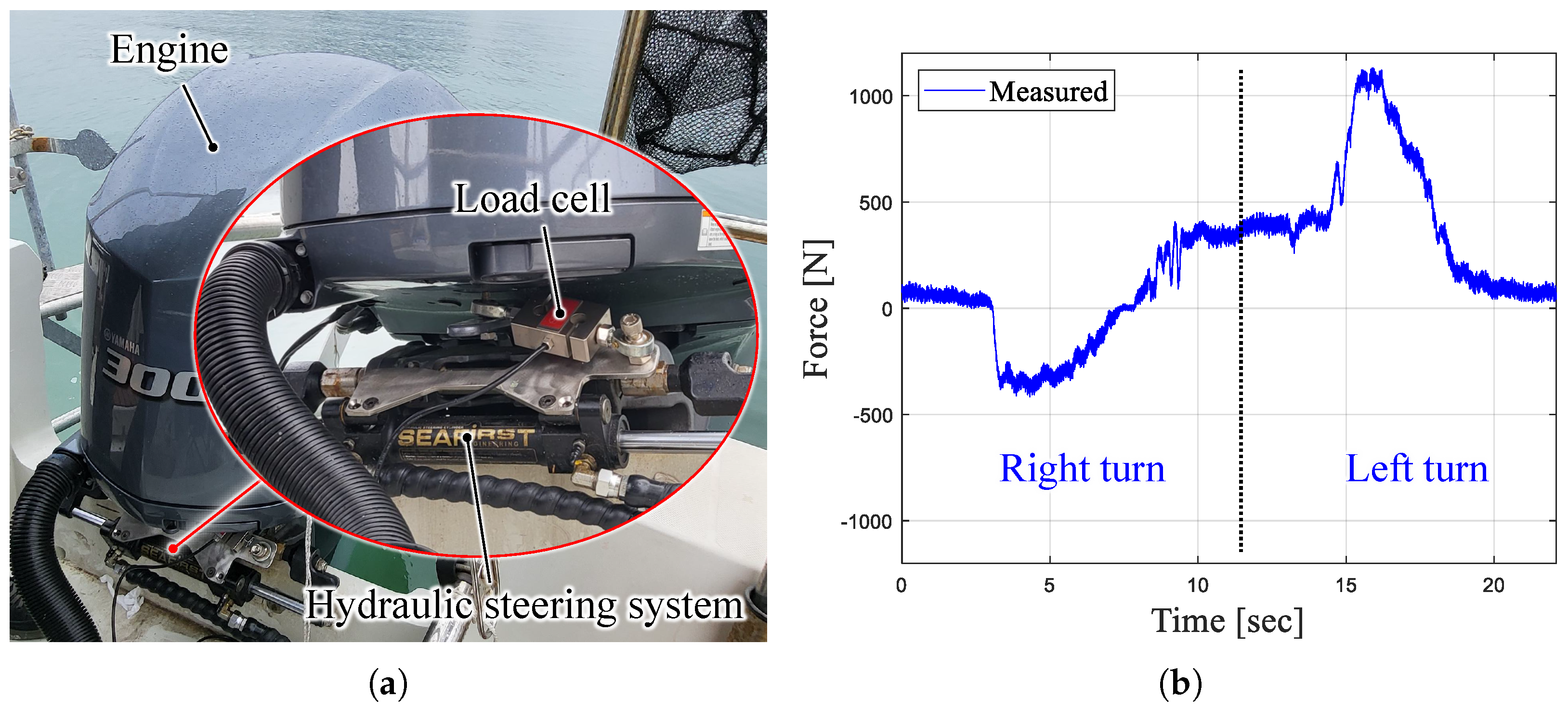
  • An experimental analysis of the thrust requirements for engine direction control in real maritime environments.
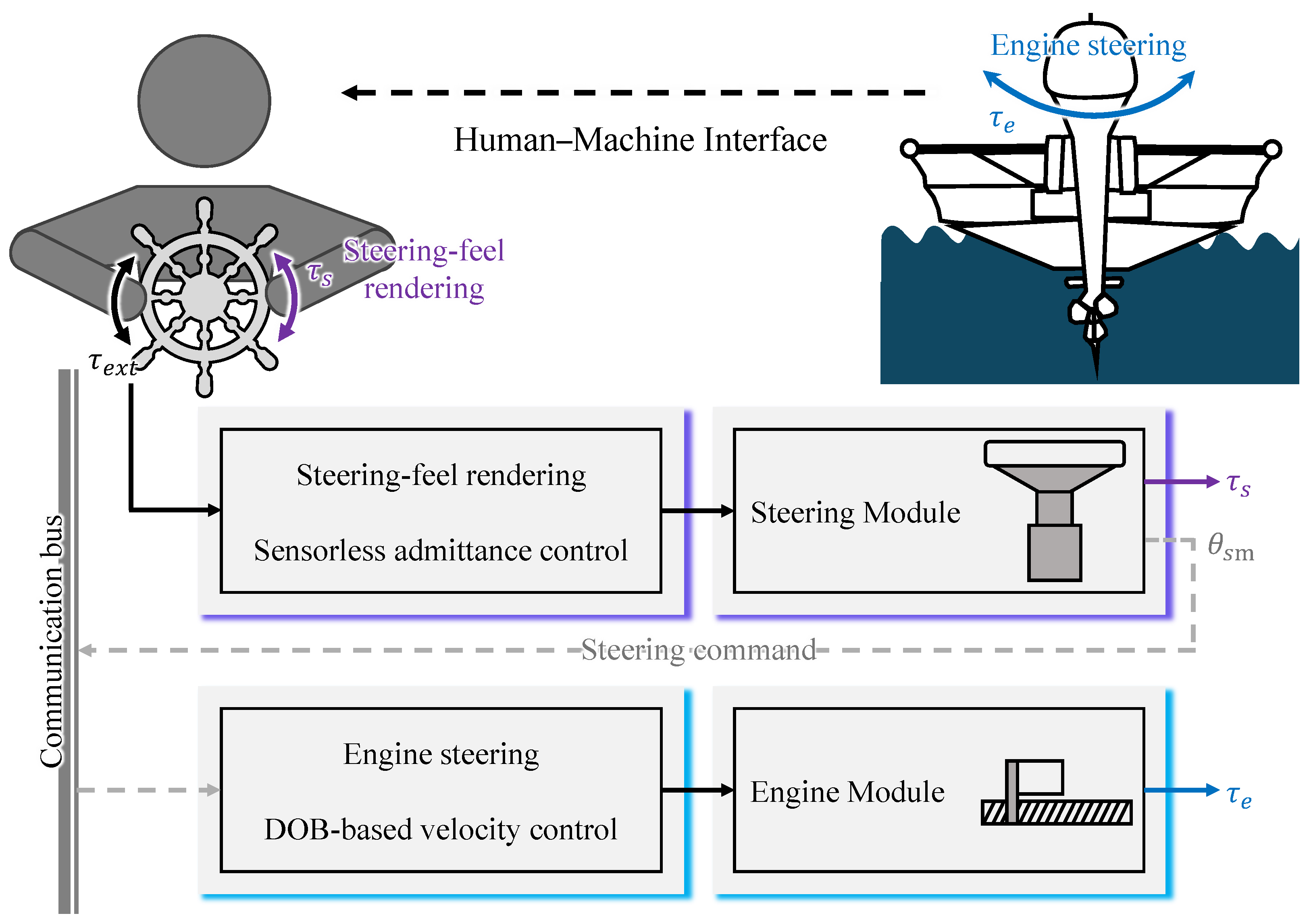
  • The application of a DOB-based steering control algorithm and a sensorless admittance control-based steering-feel rendering algorithm in the SBW system.
The remainder of this paper is organized as follows. Section 2 describes the operational principles and components of the proposed SBW system for marine vessels. Section 3 explains the control strategies employed to steer engine direction and render a steering feel, with a focus on DOB-based steering control and sensorless admittance control. In Section 4, the experimental results and performance evaluations are presented to validate the effectiveness of the proposed system in both engine steering control and rendering a steering feel. Finally, Section 5 concludes this paper.

2. Design of a SBW System for Marine Vessels

This section details the principles and components of the SBW system for marine vessels. Next, based on the experimental results obtained in real maritime environments, the thrust requirements necessary for system design are presented. Finally, a prototype of the SBW system for marine vessels is designed based on these findings.

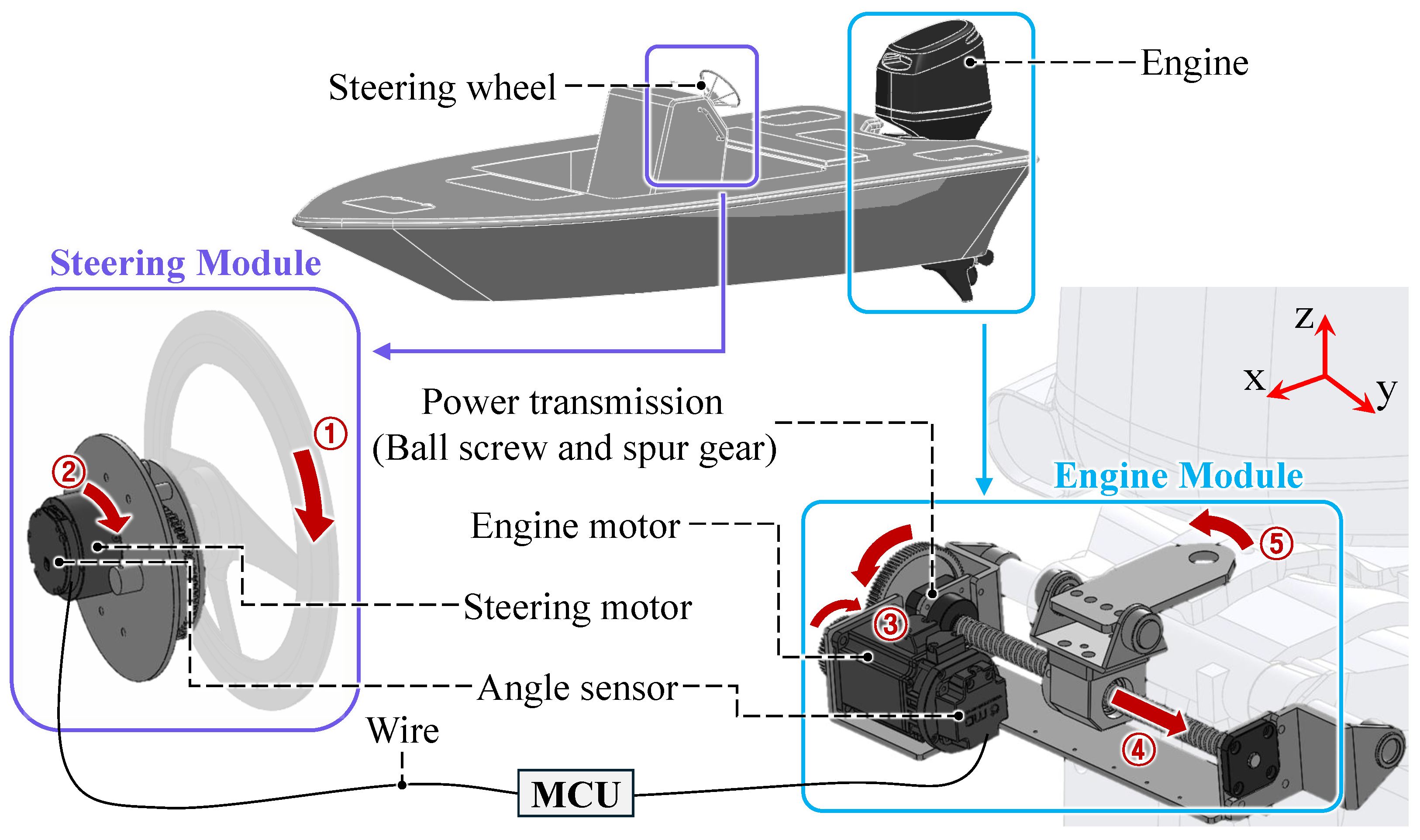
2.1. Overall Architecture of the SBW System for Marine Vessels

The architecture of the SBW system for marine vessels is similar to that of SBW systems used in vehicles and generally comprises two components: a road-wheel actuator (RWA) that controls the vehicle’s steering direction and a steering feel actuator (SFA) that generates driver feedback force based on road surface conditions [21]. The distinction between land and marine applications lies in the operating environment. In marine applications, the objective is to control engine direction rather than wheel motion. Additionally, land vehicles require feedback through the wheels to convey road irregularities—such as bumps and textures—to the driver. In contrast, such surface variations do not exist in maritime environments. Instead, the SBW system focuses on enabling the operator to steer with ease, minimizing physical effort, and ensuring smooth maneuverability during navigation. The control strategies for engine direction steering and steering-feel rendering are detailed in Section 3.
Figure 1 shows an overview of the SBW system for marine vessels. The SBW system for marine vessels includes four units: a steering motor, an engine motor, an angle sensor, and a power transmission. To enhance clarity, the SBW system for marine vessels is divided into two modules: the steering module and the engine module.
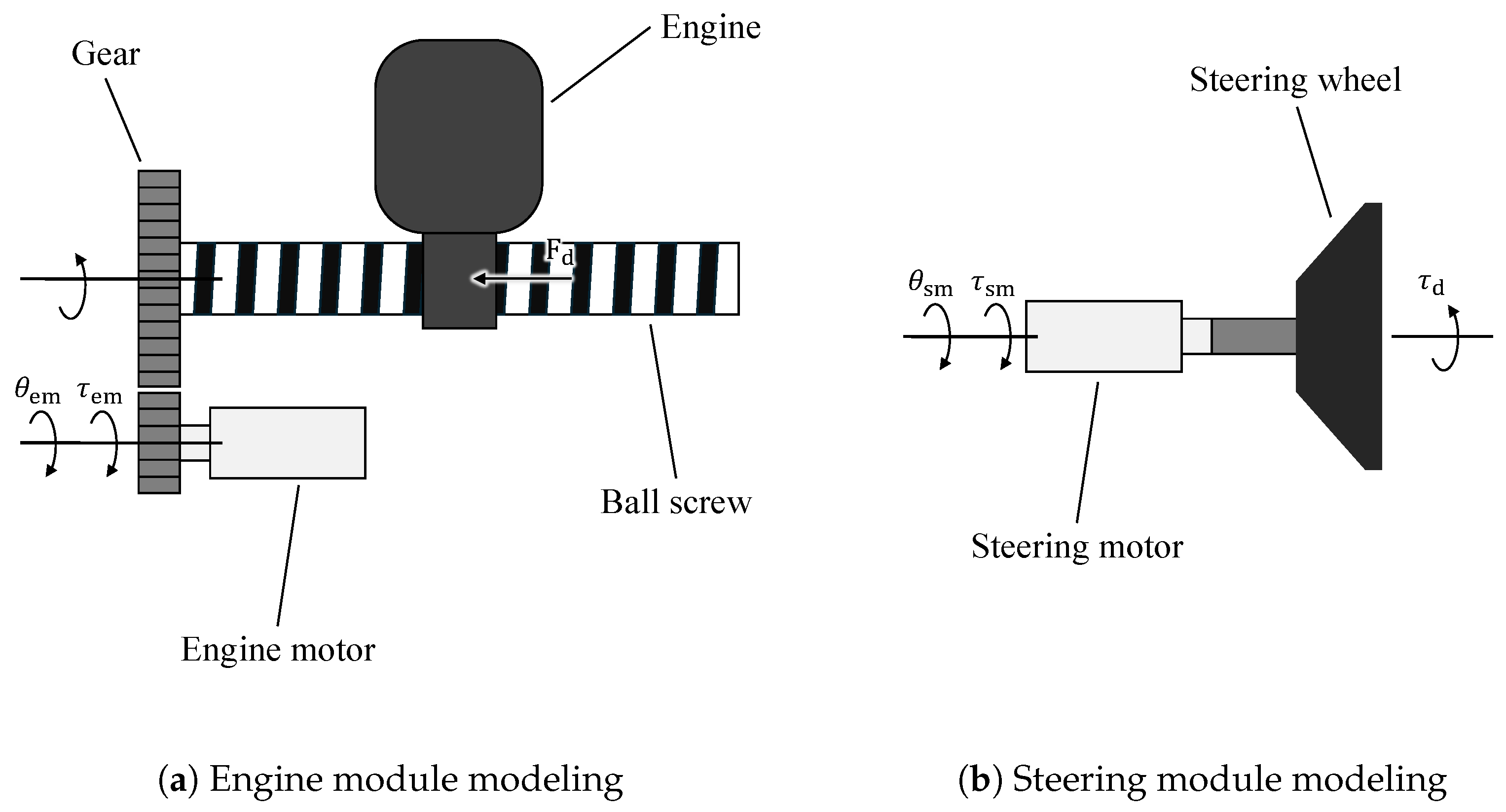
  • Engine module: This module consists of the components on the right side and executes control signals to adjust the engine direction, aligning it with the steering command.
  • Steering module: This module consists of the components on the left side and processes control signals to render steering feel for the operator. It also makes steering commands in direct response to operator inputs.
The operational sequence of the SBW system for marine vessels consists of five steps. First, when the operator turns the steering wheel, the steering motor produces a steering-feel rendering. Second, an angle sensor detects the resulting rotational displacement. Third, the detected rotation triggers the engine motor. Fourth, the power transmission mechanism translates the engine motor’s rotation into the rotational movement of the engine. Finally, the engine’s directional change is executed. The detailed mechanisms of the steering module and engine module are presented in the following subsections.

2.2. Engine Module

Figure 2a shows the mechanism of the engine module. The engine module utilizes a ball screw mechanism to produce linear motion, which is converted into rotational motion of the engine through rotational degrees of freedom at each joint. Ball screws feature a compact design and high reduction ratio [22], which result in significant thrust capacity while maintaining low backlash and high precision compared to other drive mechanisms. The low lead angle minimizes back-drivability and reduces the impact of external disturbances on the motor in harsh marine environments. Although ball screws can exhibit issues such as screw whip during long strokes and increased sensitivity to wear, these drawbacks are mitigated by the short stroke requirements for engine rotation in marine vessels. Figure 2b presents a top view of this rotation process along with a sectional view of the engine module. The engine axis is connected to frame 1 through the engine linkage and bushings. Bushings are attached at both ends of the engine linkage, linking it to the ball screw. In response to the steering module’s command, the engine motor rotates the ball screw, generating translational motion along the y 2 axis. This motion induces rotational movement around the z 1 and y 2 , 3 axis, ultimately enabling the rotation of the engine. The length of the ball screw is a parameter in determining the engine’s rotation angle, which directly influences the vessel’s steering performance and turning radius. The ball screw length can be expressed as follows:
l b = 2 × r × sin ( θ m a x ) ,
where l b is the length of the ball screw, r is the turning radius of the engine, and θ m a x is the maximum rotation angle. Since the maximum rotation angle and turning radius depend on the engine specifications, it is necessary to design the SBW system for marine vessels to accommodate these variations. In this paper, the maximum rotation angle is set between 30 and 30 , with a turning radius of 195 mm. A ball screw with a stroke length of 200 mm is selected to meet these requirements. Moreover, using Equation (1), the engine’s rotation angle can be calculated without additional sensors, simplifying the SBW system for marine vessel configuration. The rotation angle θ is given as follows:
θ = sin 1 ( d r ) ,
where d is the displacement of the engine linkage along the y axis. Since the turning radius r remains constant, d can be measured using a steering angle sensor, enabling accurate estimation of the engine’s rotation angle.

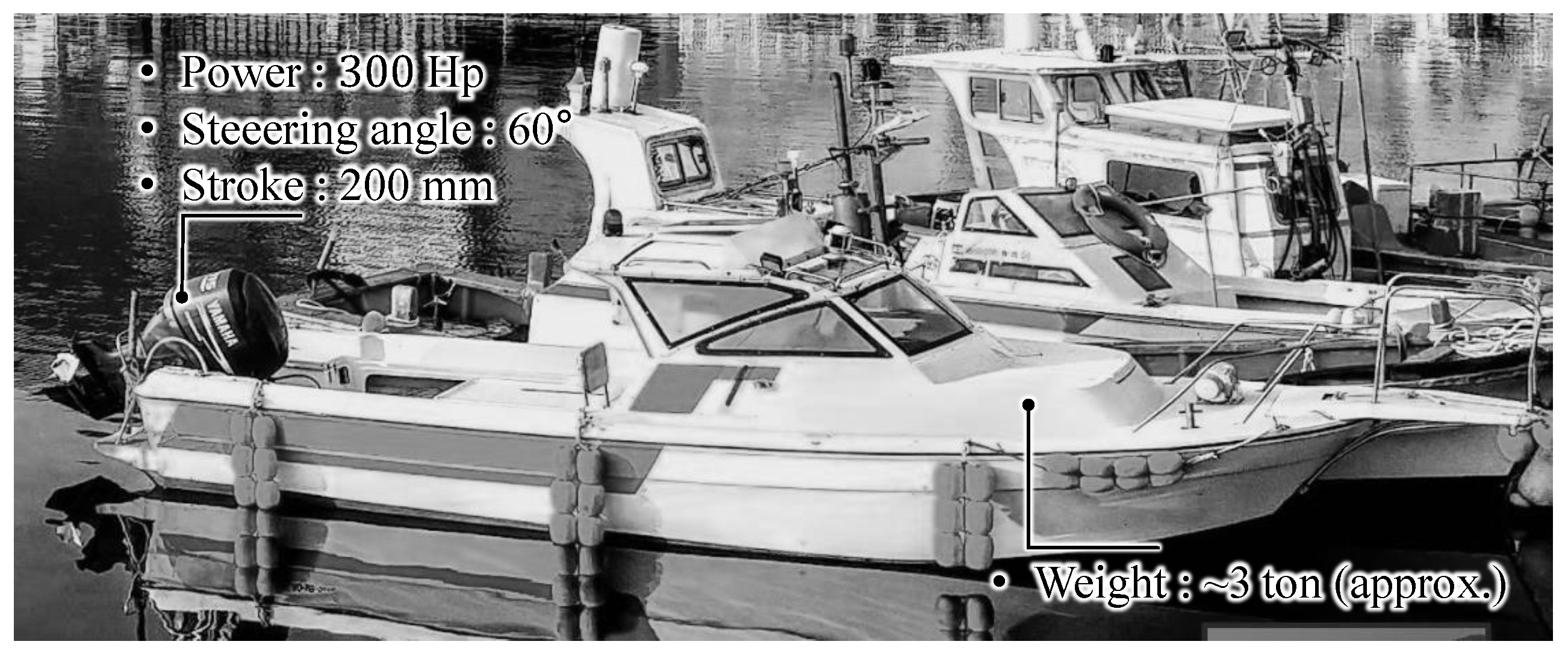
2.3. Thrust Required for Engine Steering

To design the engine module, it is necessary to quantitatively evaluate the thrust required for steering the vessel’s engine. Therefore, this study experimentally investigated the thrust required for steering under real maritime conditions, providing data for engine module design. Figure 3 shows the specifications of the tested vessel. The experiment was carried out on a 3-ton outboard motorboat equipped with a hydraulic steering system. Figure 4a illustrates the experimental setup conducted in an actual maritime environment. A load cell was mounted on the hydraulic cylinder linkage to measure the thrust generated during engine steering. The vessel was tested during maximum-speed left and right turns, at which point the maximum load on the engine was recorded.
The load cell measurements were collected at these points to quantify the thrust required for engine steering. Figure 4b presents the thrust data obtained from the experiment. The graph is divided into two sections, left and right turns, with maximum thrust values recorded as 470 N and 1130 N, respectively. This difference is caused by the unidirectional rotation of the engine’s propeller, which produces uneven thrust. The results show that the engine motor is subjected to a continuous load during operation, and at least 1130 N of thrust is required to move the hydraulic cylinder at a velocity of 50 mm/s.

2.4. Steering Module

A design consideration for the steering module is accurate steering wheel homing to maintain alignment between operator input and the engine’s orientation. This ensures consistent control performance, even when the SBW system for marine vessels is powered off and restarted. To achieve this, an absolute encoder is integrated with a spur gear for precise homing. As shown in Figure 5, the steering wheel is directly connected to the steering motor, and the absolute encoder is driven by a 4:1 reduction gear. This configuration allows a maximum steering wheel rotation of 3.5 turns from lock to lock, effectively limiting the range to 1.75 turns in each direction. Mechanical stoppers are installed on both the gear and the base to prevent further rotation when the steering wheel reaches its limit.

2.5. Prototype of the SBW System for Marine Vessels

A prototype of the SBW system for marine vessels was developed based on the analyses in the preceding sections, as illustrated in Figure 6. The SBW system for marine vessels comprises a steering module and an engine module, each equipped with actuators utilizing rotary motors and gear reducers. The gear reducers increase the motor’s torque output, reducing the required motor rating and overall actuator cost. The steering module employs a servo motor (MG4005E-i10v3) from KmTech Co. (Changzhou, China) with a 10:1 gear ratio, delivering a rated torque of 4 Nm to render a steering feel. In the engine module, a BLDC motor (BL6 Series) from MDrobot Co. (Seoul, Republic of Korea) is utilized, providing a rated torque of 0.65 Nm. This motor is paired with a 2:1 gear ratio ball screw with a 5 mm lead, enabling the precise control of the engine’s rotation angle.

3. Control Algorithm Design of the SBW System for Marine Vessels

This section provides a detailed description of the control strategies and algorithms implemented for vessel steering and for rendering a steering feel in the proposed SBW system. It includes DOB-based velocity control and sensorless admittance control.

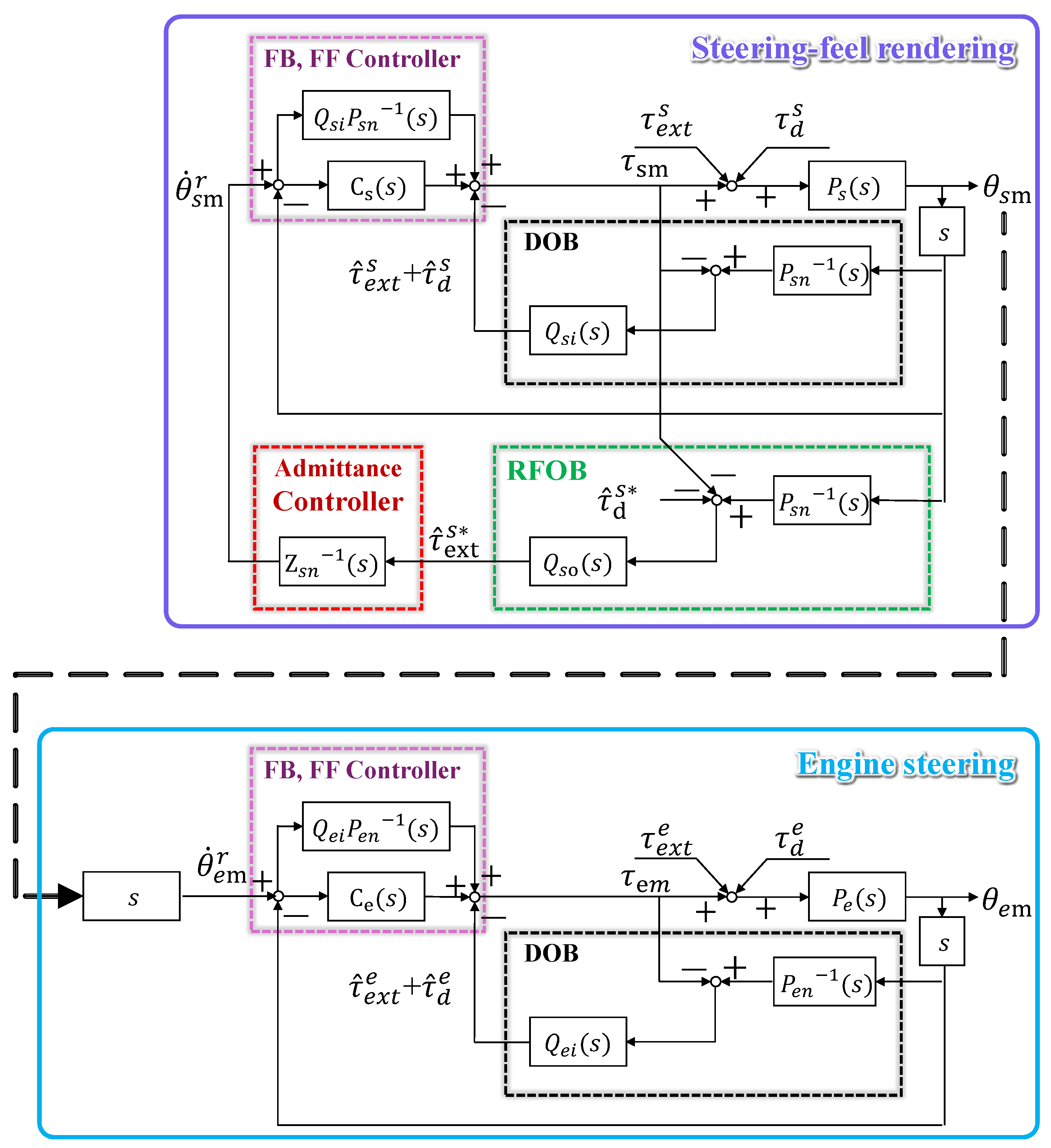
3.1. Overall Control Structure of the SBW System for Marine Vessels

Figure 7 presents the overall control structure of the proposed SBW system for marine vessels. This structure illustrates a human–machine interface process in which the operator’s turning of the steering wheel not only controls the vessel’s direction but also provides real-time feedback on the vessel’s movement. Additionally, the steering module includes a mechanism for rendering a steering feel on the wheel. Both modules utilize robust velocity control, integrating a DOB and a PI controller. The engine module tracks the rotation angle of the steering motor θ s m , and produces the torque τ e needed to align the engine direction with the steering wheel angle. The steering module applies sensorless admittance control to render adaptive steering feel, represented as τ s , in response to operator input τ e x t .

3.2. DOB-Based Velocity Control for Engine Steering

The accurate control of engine direction in response to steering wheel inputs is crucial for safe and efficient navigation. In maritime environments, where unpredictable disturbances frequently occur, a robust control strategy is necessary to maintain consistent performance. A DOB is commonly used as an effective control method for estimating and compensating for disturbances. By utilizing the estimated disturbance as a feedback signal, the SBW system’s disturbance rejection capability is enhanced [23]. Figure 8 illustrates the block diagram of the engine module using the DOB-based velocity controller. The control system comprises an inverse plant model P e n 1 ( s ) and a disturbance estimation filter Q e i ( s ) . The Q e i ( s ) filter estimates and cancels disturbances, represented as τ ^ e x t e and τ ^ d e . These estimated disturbances are compensated for in the control input, thereby minimizing the adverse effects of external disturbances on system performance. The DOB structure can be mathematically expressed as follows:
θ ˙ e m τ e m = 1 ( 1 Q e i ( s ) ) P e 1 ( s ) + Q e i ( s ) P e n 1 ( s )
In Equation (3), increasing the bandwidth of the Q e i ( s ) filter enables the ratio θ ˙ e m τ e m to more closely approximate the plant response. This underscores the significance of the Q e i ( s ) filter bandwidth in improving the SBW system’s robustness and performance. The velocity controller, based on the DOB, combines a feedforward loop and a feedback loop with PI control to achieve robust disturbance rejection. The feedforward controller is defined as Q e i ( s ) P e n 1 ( s ) , accounting for the normalized plant dynamics estimated by the DOB. When the actual plant closely approximates the nominal model, the system with DOB demonstrates exceptional performance [24]. Even a control scheme based solely on feedforward control can secure adequate control bandwidth by increasing the Q e i ( s ) filter’s bandwidth. However, in real marine environments, differences in the actual plant parameters arise, which necessitates the use of a feedback controller alongside the feedforward controller to achieve high-performance velocity control. The feedback controller C e ( s ) is selected as the PI. The transfer function of the PI controller is as follows:
C e ( s ) = K P s + K I s ,
where K P and K I are the proportional and integral feedback gain. The PI gain values were designed via pole-zero cancellation and subsequently fine-tuned through trial-and-error based on the actual system response. This structure reduces the impact of disturbances on overall performance and ensures precise velocity control.

3.3. Admittance Control for Steering-Feel Rendering

An admittance controller is a force-based control method widely used in systems requiring dynamic human–machine interaction. It senses external forces or torques and converts them into appropriate motion, enabling smooth interaction with humans. Implementing this method requires precise and robust velocity control, as well as an external force estimation mechanism. In this paper, a DOB-based sensorless admittance control was utilized to ensure effective operator interaction. The steering module control in Figure 8 combines the robust DOB-based velocity control with a sensorless admittance controller. The DOB not only eliminates disturbances but also estimates external forces through the Reaction Force Observer (RFOB). Based on this, the loop designed to render steering feel is as follows. Similar to the control method used in the engine module, the Q filter Q s i ( s ) in the inner-loop DOB ensures disturbance rejection and maintains nominal plant behavior up to its bandwidth. Speed control is also achieved by designing an external feedback controller C s ( s ) and a feedforward controller Q s i P s n 1 ( s ) . By applying the velocity command generated through the force estimated by the RFOB and the admittance model to the designed speed controller, the desired steering feel can be rendered.
The RFOB is designed to estimate the operator-applied input forces τ ^ e x t s * during external interactions [25]. It improves the accuracy of force estimation by compensating for uncertainties in the SBW system model and internal dynamic disturbances τ ^ d s * . Likewise, the bandwidth of the Q s o ( s ) filter plays a critical role in the performance of the RFOB, ensuring reliable and stable force estimation. The estimated external forces generate the reference velocity signal according to the following equation:
τ ^ e x t s * Z s n 1 ( s ) = θ ˙ s m r ,
where the admittance model Z s n 1 ( s ) processes the estimated external forces τ ^ e x t s * to produce the reference velocity signal θ ˙ s m r based on the operator’s input steering force. This velocity causes the SBW system to output a torque that renders the steering feel to the operator. The admittance model Z s n 1 ( s ) is defined as follows:
Z s n 1 ( s ) = s J s n s 2 + B s n s + K s n ,
where J s n , B s n , and K s n represent the virtual inertia, damping, and stiffness coefficients, respectively. The model presented in Equation (6) plays an important role in controlling the steering feel that is rendered in response to operator input.
The dynamic characteristics of the steering-feel rendering produced by the steering module can be adjusted by tuning these parameters. The torque for rendering a steering feel is expressed as follows:
τ s = J s n θ ¨ s m ( t ) + B s n θ ˙ s m ( t ) + K s n θ s m ( t ) ,
where τ s represents the steering torque. By adjusting these parameters, customized steering-feel rendering can be achieved to deliver the desired steering torque according to operator preferences. In other words, when these parameters are increased, they result in higher inertia, damping, and stiffness. Conversely, when they are decreased, the opposite effect is observed. This allows the SBW system to render a steering feel that meets operator requirements, using only an encoder without the need for additional force sensors.

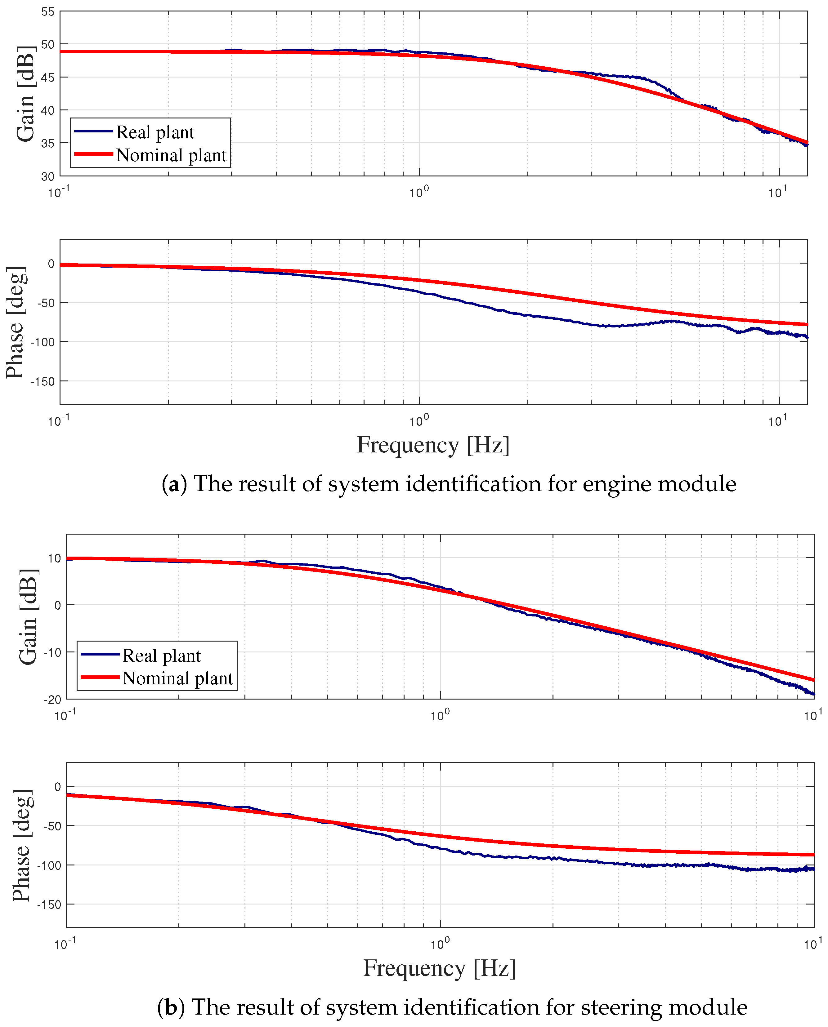
3.4. System Modeling of the SBW System for Marine Vessels

Figure 9 illustrates the schematic diagram of the SBW system for marine vessels. Each module of the SBW system for marine vessels is modeled as a multi-mass system based on the motor’s dynamic equations, with additional inertia and damping incorporated according to the specific characteristics of each module. In the engine module, the engine motor is connected to the engine via a power transmission mechanism. The dynamic equations incorporating these elements are given as follows:
J e m + J t + M L 2 ( 2 π ) 2 N 2 θ ¨ e m + B e m + B t + C L 2 ( 2 π ) 2 N 2 θ ˙ e m = τ e m L 2 π N F d ,
where τ is torque, J is inertia, B is friction coefficient, N is gear ratio, L is ball screw lead, subscript em is engine motor, and subscript t is transmission unit. Additionally, M and C represent the mass and damping properties of the nut mechanism linking the engine to the drive. F d is the disturbance force acting on the engine module. Additional inertia and damping are derived by reflecting the dynamic contributions of the power transmission components back to the motor shaft through the gear ratio N and the ball screw lead L. Specifically, linear motion associated with the nut is transformed into a rotational motion, yielding added inertia and damping that appear in the engine motor’s dynamic equation. In contrast, in the steering module, the steering motor is directly coupled to the steering wheel and its dynamics are modeled as follows:
J s m + J s w θ ¨ s m + B s m + B s w θ ˙ s m = τ s m τ d ,
where the subscripts sm and sw denote the steering motor and steering wheel, respectively. In the steering module, the dynamic characteristics of the steering wheel are incorporated. Each module’s nominal model is derived from Equations (8) and (9).
To obtain the nominal model’s parameters, a frequency response experiment was conducted using experimental input and output signal data. In the experiment, a sinusoidal torque input τ was swept over a frequency range from 0.1 to 10 Hz over a 10 s period, and the angular velocity output θ ˙ was estimated by differentiating the encoder signals from each motor. The frequency sweep was extended to 10 Hz to fully characterize each module’s dynamic behavior, covering frequencies well beyond the maximum human–machine interaction bandwidth (up to 2.5 Hz) typically observed in human arm dynamics [26]. Each module’s frequency response was characterized by applying the Fourier transform to both the input and output signals and then computing the ratio of their magnitude and phase spectra, as illustrated in Figure 10. The blue solid line indicates the measured frequency response, and the red line is the simulated frequency response with the results.

4. Experiment

This section presents the experimental results of the engine module’s velocity control performance using the proposed controller. Additionally, the steering feel rendered by the steering module is analyzed. Moreover, a comprehensive evaluation of the SBW system’s steering performance under load conditions is provided.

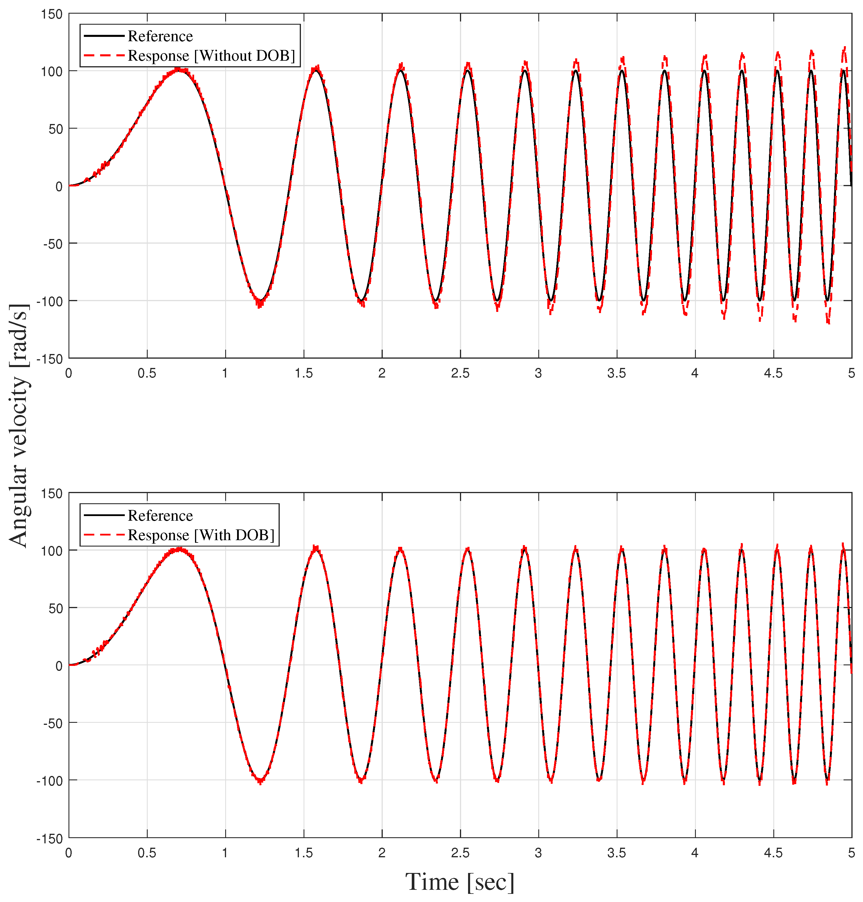
4.1. Speed Tracking Analysis Using DOB-Based Velocity Controller

This experiment was conducted to analyze the effect of the DOB-based velocity controller on the engine module’s speed tracking performance. A chirp signal was used as the velocity reference for testing. The maximum velocity was set to 15 rad/s, and the frequency increased linearly to 5 Hz within 5 s. According to the experimental results presented in Figure 11, the speed tracking performance improved when the DOB was applied. The relative RMS error, as shown in Table 1, decreased from 0.1189 (equivalent to 8.2006 rad/s) without the DOB to 0.0222 (equivalent to 1.5351 rad/s) with the DOB. This corresponds to an improvement rate of approximately 83 % , demonstrating the effectiveness of the DOB-based velocity controller in enhancing speed tracking accuracy.

4.2. Steering-Feel Rendering Analysis Using Admittance Controller

This experiment demonstrates that the proposed sensorless admittance control can render a steering feel. The effects of the admittance controller’s stiffness coefficient K s n and damping coefficient B s n on steering characteristics were analyzed. Figure 12 presents the relationship between steering torque and steering angle for variations in these parameter values. Figure 12a shows the results when adjusting the stiffness coefficient. As the stiffness coefficient increases, the graph’s slope becomes steeper. This indicates that a higher stiffness coefficient increases the physical restoring force of the steering module, resulting in a firmer steering feel. Conversely, a lower stiffness coefficient results in a gentler slope, providing a smoother and more flexible steering feel. The results for adjusting the damping coefficient are shown in Figure 12b. As the damping coefficient increases, the slope remains unchanged, while the overall spread of the curve increases. This indicates that a higher damping coefficient generates resistance proportional to velocity, resulting in a heavier steering feel. On the other hand, a lower damping coefficient reduces resistance, producing a lighter steering feel. Figure 12c presents the results of combining stiffness and damping coefficients to produce various steering characteristics.
By tuning both parameters, the steering system can achieve a range of steering characteristics, such as firmness versus smoothness and heaviness versus lightness. Notably, the combined adjustment of these two parameters demonstrates the ability to implement complex steering characteristics that cannot be achieved through individual parameter tuning alone. These findings confirm that the proposed sensorless admittance control enables the rendering of a customized steering feel that effectively meets operator preferences and requirements.

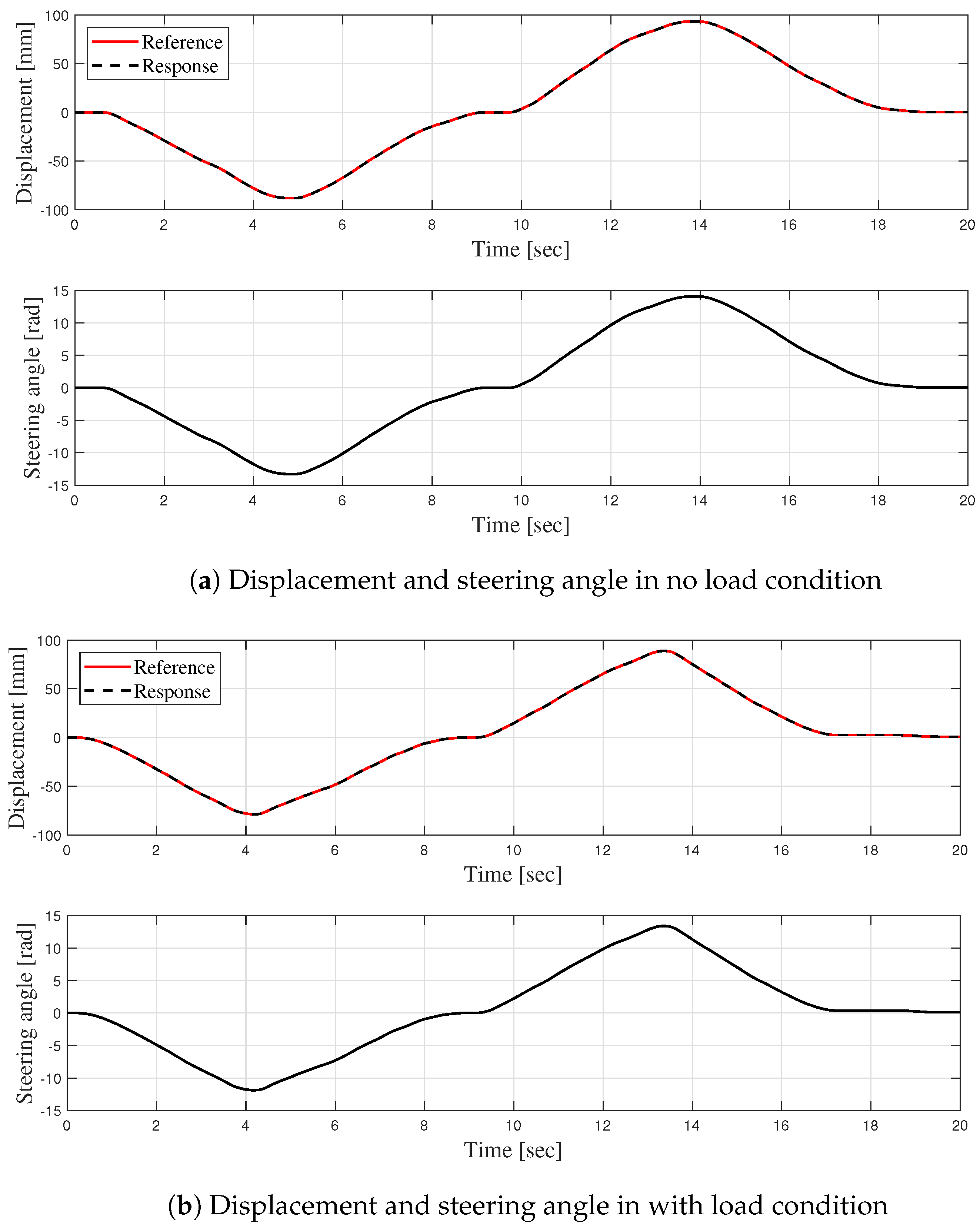
4.3. Steering Performance Analysis of the SBW System for Marine Vessels

This experiment analyzes the steering performance of the engine module in response to commands from the steering module under two conditions: no load and a simulated maritime environment with an applied load of 120 kg. These conditions were established to evaluate the SBW system’s ability to maintain steering performance both in an ideal setting and in a simulated maritime environment with external loading, where harsh forces may degrade steering accuracy. Figure 13 illustrates the experimental results. Over a 20 s period, the operator executed left–right steering actions, and the displacement of the engine module in response to the steering commands was compared. Figure 13a shows the experimental results under no load conditions, while Figure 13b presents the results under a simulated maritime environment with an applied load of 120 kg. As presented in Table 2, the RMS error under no load conditions was 0.0222 mm, whereas under an applied load of 120 kg, it increased to 0.0307 mm. These results suggest that external loading introduces additional dynamic effects that can slightly reduce steering precision.
Nevertheless, the overall error remains low, indicating that the SBW system for marine vessels maintains effective steering performance even under simulated maritime loading conditions.

5. Conclusions

5.1. Summary

This study presents a novel SBW system for marine vessels that integrates a cost-effective power transmission mechanism with advanced control strategies, including a DOB-based velocity controller and a sensorless admittance control scheme for steering-feel rendering. The proposed SBW system is designed to operate reliably under external loads and renders adjustable steering feel using only encoder feedback, thereby eliminating the need for additional sensors. In contrast to conventional systems, it can be scaled and adapted to various vessel types. The experimental results, including analyses of steering performance and steering-feel rendering, demonstrate its applicability in marine environments.

5.2. Discussion

The novel SBW system for marine vessels addresses several limitations identified in previous studies. While many earlier works have relied on direct-drive actuators that, although capable of generating high thrust, tend to be expensive and complex, the proposed SBW system adopts a cost-effective power transmission mechanism. However, this cost-effective approach may involve trade-offs in terms of mechanical robustness and precision under extreme maritime conditions, warranting further experimental validation to ensure reliable long-term performance. In addition, the control method integrates a DOB-based velocity controller with a sensorless admittance control scheme to render steering feel. While the relatively slow dynamics of marine vessels favor this sensorless approach, it remains highly dependent on the accuracy of the system model. Any deviations from the assumed dynamics or unforeseen disturbances could degrade performance, particularly during transient events or rapid changes in environmental conditions. Consequently, further validation and refinement of the model are essential to ensure the SBW system’s adaptability and reliability in diverse operational scenarios.
These considerations highlight the need for further long-term testing and robust design strategies to ensure reliability and performance across the broad range of conditions encountered in marine applications. By evaluating the trade-offs shown in Table 3, future developments can focus on integrating the benefits of each system type while mitigating potential vulnerabilities, advancing the effectiveness of marine steering technologies.

5.3. Future Work

Future work should expand the experimental testing of the SBW for marine vessels to evaluate improvements in steering performance, long-term durability, adaptability under diverse maritime conditions, and potential failure scenarios. In this regard, contingency measures—such as enabling remote control to directly adjust the engine module’s direction in the event of a steering motor failure or designing a handle interface to manually rotate the ball screw if the engine module malfunctions—are under consideration. Furthermore, although the current study is a feasibility test rather than a complete product development process, integrating tests under a broader range of maritime conditions is expected to significantly enhance practical applicability. Therefore, performance verification will be conducted through repeated tests in actual maritime environments—characterized by diverse and dynamic conditions—using the SBW system for marine vessels. Moreover, the performance output of the proposed SBW system varies significantly with the selection of the drive motor and the configuration of the power transmission mechanism, underscoring its substantial potential for customization and scalability across diverse vessel types. Expanding the SBW system’s power transmission and control capabilities to accommodate various vessels will be an important step. Additionally, incorporating autonomous driving capabilities into the proposed SBW system could further advance its functionality and pave the way for new research avenues in next-generation marine vessel control.

Author Contributions

Conceptualization, C.L.; Methodology, C.L.; Software, D.K.; Validation, D.K.; Formal Analysis, D.K.; Investigation, D.K.; Resources, C.L.; Data Curation, D.K.; Writing—Original Draft Preparation, D.K.; Writing—Review and Editing, C.L.; Visualization, D.K.; Supervision, C.L.; Project Administration, C.L.; Funding Acquisition, C.L. All authors have read and agreed to the published version of the manuscript.

Funding

This work was supported by the 2021 Yeungnam University Research Grant.

Institutional Review Board Statement

Not applicable.

Informed Consent Statement

Not applicable.

Data Availability Statement

The original data presented in the study are openly available in GitHub at https://github.com/Deokgyu-Kim-Yeungnam/JMSE-Data-3517754.

Conflicts of Interest

The authors declare no conflict of interest.

References

  1. Karanović, V.; Ceylan, B.O.; Jocanović, M. Reliable Ships: A Fuzzy FMEA-Based Risk Analysis on Four-Ram Type Hydraulic Steering System. Ocean Eng. 2024, 314, 119758. [Google Scholar] [CrossRef]
  2. Rao, G.G.; Pasumarthi, M.R. Development of Modern Electrical Steering Gear System on Board Ships with Autopilot. Int. Res. J. Eng. Technol. 2019, 6, 2846–2850. [Google Scholar]
  3. Kumar, P.; Park, S.; Zhang, Y.; Jo, S.H.; Kim, H.S.; Kim, T. A Review of Hydraulic Cylinder Faults, Diagnostics, and Prognostics. Int. J. Precis. Eng. Manuf.-Green Tech. 2024, 11, 1637–1661. [Google Scholar] [CrossRef]
  4. Mortazavizadeh, S.A.; Ghaderi, A.; Ebrahimi, M.; Hajian, M. Recent Developments in the Vehicle Steer-by-Wire System. IEEE Transp. Electrif. 2020, 6, 1226–1235. [Google Scholar] [CrossRef]
  5. Wang, W.; Chen, X.; Wang, J. Motor/Generator Applications in Electrified Vehicle Chassis—A Survey. IEEE Transp. Electrif. 2019, 5, 584–601. [Google Scholar] [CrossRef]
  6. Sung, J.; Choi, S.; Huh, K. A Differential Brake-Actuated Steering System for Redundancy of Steer-by-Wire. IEEE Intell. Veh. 2024, 9, 993–1004. [Google Scholar] [CrossRef]
  7. Fahami, S.M.H.; Zanzuri, H.; Mazlan, H.; Saiful, A.; Zulkarnain; Noraishikin, B. The Design of Vehicle Active Front Steering Based on Steer by Wire System. Adv. Sci. Lett. 2013, 19, 61–65. [Google Scholar] [CrossRef]
  8. Robert Bosch GmbH (Ed.) Bosch Automotive Electrics and Automotive Electronics: Systems and Components, Networking and Hybrid Drive; Springer Science & Business Media: Berlin/Heidelberg, Germany, 2013. [Google Scholar]
  9. Hoseinnezhad, R.; Bab-Hadiashar, A. Missing Data Compensation for Safety-Critical Components in a Drive-by-Wire System. IEEE Trans. Veh. Technol. 2005, 54, 1304–1311. [Google Scholar] [CrossRef]
  10. Bruzzese, C. A high absolute thrust permanent magnet linear actuator for direct drive of ship’s steering gears: Concept and FEM analysis. In Proceedings of the 2012 XXth International Conference on Electrical Machines, Marseille, France, 2–5 September 2012; pp. 556–562. [Google Scholar] [CrossRef]
  11. Bruzzese, C.; Rafiei, M.; Teodori, S.; Santini, E.; Mazzuca, T.; Lipardi, G. Electrical, Mechanical and Thermal Design by Multiphysics Simulations of a Permanent Magnet Linear Actuator for Ship Rudder Direct Drive. In Proceedings of the 2017 AEIT International Annual Conference, Cagliari, Italy, 20–22 September 2017; pp. 1–6. [Google Scholar] [CrossRef]
  12. Bruzzese, C.; Ruggeri, E.; Rafiei, M.; Zito, D.; Santini, E.; Mazzuca, T. Mechanical Arrangements Onboard Ship of Innovative Permanent Magnet Linear Actuators for Steering Gear. In Proceedings of the 2017 International Symposium on Power Electronics (Ee), Novi Sad, Serbia, 19–21 October 2017; pp. 1–6. [Google Scholar] [CrossRef]
  13. Mazzuca, T.; Bruzzese, C. Project “ISO”: Innovative Solutions for Italian Navy’s Onboard Full-Electric Actuators. In Proceedings of the 2012 Electrical Systems for Aircraft, Railway and Ship Propulsion (ESARS), Bologna, Italy, 16–18 October 2012; pp. 1–6. [Google Scholar] [CrossRef]
  14. Hemsen, J.; Nowak, N.; Eckstein, L. Production Cost Modeling for Permanent Magnet Synchronous Machines for Electric Vehicles. Automot. Engine Technol. 2023, 8, 109–126. [Google Scholar] [CrossRef]
  15. Ruiz-Ponce, G.; Arjona, M.A.; Hernandez, C.; Escarela-Perez, R. A Review of Magnetic Gear Technologies Used in Mechanical Power Transmission. Energies 2023, 16, 1721. [Google Scholar] [CrossRef]
  16. Lee, J.; Chang, S.; Kim, K.; Jang, B.; Lee, D.; Lee, B.; Yi, K. Steering Wheel Torque Control of Steer-by-Wire System for Steering Feel; SAE Technical Paper; SAE International: Warrendale, PA, USA, 2017. [Google Scholar] [CrossRef]
  17. Oh, S.-W.; Chae, H.-C.; Yun, S.-C.; Han, C.-S. The Design of a Controller for the Steer-by-Wire System. JSME Int. J. Ser. Mech. Syst. Mach. Elem. Manuf. 2004, 47, 896–907. [Google Scholar] [CrossRef]
  18. Cheon, D.S.; Nam, K.H. Steering Torque Control Using Variable Impedance Models for a Steer-by-Wire System. Int. J. Automot. Technol. 2017, 18, 263–270. [Google Scholar] [CrossRef]
  19. Im, J.S.; Ozaki, F.; Matsunaga, M.; Kawaji, S. Design of Steer-by-Wire System with Bilateral Control Method Using Disturbance Observer. In Proceedings of the 2007 IEEE/ASME International Conference on Advanced Intelligent Mechatronics, Zurich, Switzerland, 4–7 September 2007; pp. 1–6. [Google Scholar] [CrossRef]
  20. Kopczynski, T.; Ness, D. Five Factors That Can Affect Your Weighing System’s Accuracy. Powder Bulk Eng. 2001, 15, 31–37. [Google Scholar]
  21. Onoda, Y.; Onuma, Y.; Goto, T.; Sugitani, T. Design Concept and Advantages of Steer-by-Wire System; SAE Technical Paper 2008-01-0493; SAE International: Warrendale, PA, USA, 2008. [Google Scholar] [CrossRef]
  22. Haus, R. Converting Rotary Motion to Linear Motion. Power Convers. Intell. Motion 1996, 22, 72–74. [Google Scholar]
  23. Komada, S.; Ishida, M.; Ohnishi, K.; Hori, T. Disturbance Observer-Based Motion Control of Direct Drive Motors. IEEE Trans. Energy Convers. 1991, 6, 553–559. [Google Scholar] [CrossRef]
  24. Kempf, C.J.; Kobayashi, S. Disturbance Observer and Feedforward Design for a High-Speed Direct-Drive Positioning Table. IEEE Trans. Control Syst. Technol. 1999, 7, 513–526. [Google Scholar] [CrossRef]
  25. Oh, S.; Kong, K.; Hori, Y. Design and Analysis of Force-Sensor-Less Power-Assist Control. IEEE Trans. Ind. Electron. 2014, 61, 985–993. [Google Scholar] [CrossRef]
  26. Kalinowska, A.; Schlafly, M.; Rudy, K.; Dewald, J.P.; Murphey, T.D. Measuring Interaction Bandwidth During Physical Human-Robot Collaboration. IEEE Robot. Autom. Lett. 2022, 7, 12467–12474. [Google Scholar] [CrossRef]
  27. Akers, A.; Gassman, M.; Smith, R. Hydraulic Power System Analysis; CRC Press: Boca Raton, FL, USA, 2006. [Google Scholar]
  28. Tang, X.; Wu, C.; Xu, X. Learning-Based Nonlinear Model Predictive Controller for Hydraulic Cylinder Control of Ship Steering System. J. Mar. Sci. Eng. 2022, 10, 2033. [Google Scholar] [CrossRef]
  29. Bruzzese, C.; Tessarolo, A.; Mazzuca, T.; Scala, G. A Closer Look to Conventional Hydraulic Ship Actuator Systems and the Convenience of Shifting to (Possibly) All-Electric Drives. IEEE Electr. Ship Technol. Symp. (ESTS) 2013, 2013, 220–227. [Google Scholar] [CrossRef]
  30. Huang, S.-J.; Wang, S.-S. Mechatronics and Control of a Long-Range Nanometer Positioning Servomechanism. Mechatronics 2009, 19, 14–28. [Google Scholar] [CrossRef]
Figure 1. Overview of the SBW system for marine vessels.
Jmse 13 00582 g001
Figure 2. Engine rotation motion conversion in SBW system for marine vessels. (a) Ball screw mechanism in the engine module; (b) top view of engine rotation mechanism.
Jmse 13 00582 g002
Figure 3. Tested vessel and its technical characteristics.
Jmse 13 00582 g003
Figure 4. Thrust analysis for engine steering in a maritime environment. (a) Experimental setup for measuring thrust in maritime steering; (b) measured thrust during left and right turns.
Jmse 13 00582 g004
Figure 5. Configuration of steering module.
Jmse 13 00582 g005
Figure 6. Prototype SBW system for marine vessels.
Jmse 13 00582 g006
Figure 7. Control structure of the SBW system for marine vessels.
Jmse 13 00582 g007
Figure 8. Block diagram for engine steering and steering-feel rendering in the SBW system for marine vessels.
Jmse 13 00582 g008
Figure 9. System modeling of the SBW for marine vessels.
Jmse 13 00582 g009
Figure 10. Frequency responses of the SBW system for marine vessels.
Jmse 13 00582 g010
Figure 11. Effect of DOB-based velocity control on speed tracking performance.
Jmse 13 00582 g011
Figure 12. Experiment results for various admittance parameters and conditions. (a) Crossplot of steering wheel torque-angle for stiffness coefficient variations; (b) crossplot of steering wheel torque-angle for damping coefficient variations; (c) crossplot of steering wheel torque-angle for combined stiffness and damping coefficients.
Jmse 13 00582 g012
Figure 13. Steering performances of the SBW system for marine vessels.
Jmse 13 00582 g013
Table 1. Relative RMS error comparison without and with DOB.
Without DOBWith DOB
Relative RMS error0.11890.0222
Table 2. RMS errors in steering performance for different conditions.
ConditionRMS Error
No load0.0222  [mm]
With load0.0307  [mm]
Table 3. Comparison of different steering systems for marine vessels.
Steering Systems for Marine Vessels
HydraulicElectronic
MechanismsLinear cylinder [2,27,28]Linear motor [10,11,12,29]Linear actuation
with ball screw [15,22,30]
Advantages
  • High torque density and load capacity
  • Stability in harsh marine environments
  • Fast, precise control with direct drive
  • Low energy efficiency
  • Fewer components enable a modular, compact design
  • Compact form factor with a high reduction ratio
  • Cost-effective solution
  • Provide scalability, enabling flexible adjustment
Disadvantages
  • Many components, leading to bulky size and high weight
  • High maintenance load due to oil/filter management and risk of leaks
  • High energy consumption
  • High costs due to specialized components
  • Sensitivity to vibrations and shock
  • Wear under operational loads, mechanical friction, and backlash
  • Screw whip under high dynamic conditions
Disclaimer/Publisher’s Note: The statements, opinions and data contained in all publications are solely those of the individual author(s) and contributor(s) and not of MDPI and/or the editor(s). MDPI and/or the editor(s) disclaim responsibility for any injury to people or property resulting from any ideas, methods, instructions or products referred to in the content.

