Article

A Self-Tuning Variable Universe Fuzzy PID Control Framework with Hybrid BAS-PSO-SA Optimization for Unmanned Surface Vehicles

by
Huixia Zhang
,
Zhao Zhao
*,
Yuchen Wei
,
Yitong Liu
and
Wenyang Wu
School of Ocean Engineering, Jiangsu Ocean University, Lianyungang 222005, China
*
Author to whom correspondence should be addressed.
J. Mar. Sci. Eng. 2025, 13(3), 558; https://doi.org/10.3390/jmse13030558
Submission received: 9 February 2025 / Revised: 9 March 2025 / Accepted: 11 March 2025 / Published: 13 March 2025
(This article belongs to the Section Ocean Engineering)

Abstract

:
In this study, a hybrid heading control framework for unmanned surface vehicles (USVs) is proposed, combining variable domain fuzzy Proportional–Integral–Derivative (VUF-PID) with an improved algorithmic Beetle Antennae Search–Particle Swarm Optimization–Simulated Annealing (BAS-PSO-SA) optimization to address the multi-objective control challenge. Key innovations include a self-tuning VUF mechanism that improves disturbance rejection by 42%, a weighted adaptive optimization strategy that reduces parameter tuning iterations by 37%, and an asymmetric learning factor that balances global exploration and local refinement. Benchmarks using Rastrigin, Griewank, and Sphere functions show superior convergence and 68% stability improvement. Ocean heading simulations of a 7.02 m unmanned surface vehicle (USV) using the Nomoto model show a 91.7% reduction in stabilization time, a 0.9% reduction in overshoot, and a 30% reduction in optimization iterations. The experimental validation under wind and wave disturbances shows that the heading deviation is less than 0.0392°, meeting the IMO MSC.1/Circ.1580 standard, and an 89.5% improvement in energy efficiency. Although the processing time is 12.7% longer compared to the GRO approach, this framework lays a solid foundation for ship autonomy systems, and future enhancements will focus on MPC-based time delay compensation and Field-Programmable Gate Array (FPGA) acceleration.

1. Introduction

The heading control of unmanned surface vessels is a key area in automatic rudder research, encompassing the control of heading, position, speed, and angular velocity. The fundamental requirement for effective control is a thorough understanding of the vessel’s maneuvering characteristics. Unmanned ships operating at sea are influenced by environmental factors, such as wind, waves, and currents [1,2,3], and thus deviate from the heading. Therefore, a safe and stable controller with robust anti-interference capabilities is essential to regulate the rudder angle of the unmanned vessel, ensuring precise heading control and maintaining operational stability in dynamic marine environments [4,5]. Traditional PID controllers, while widely used, exhibit significant limitations in handling complex sea conditions and environmental disturbances, often resulting in poor control accuracy, reduced stability, and increased energy consumption, which are critical issues for autonomous maritime operations. To meet these challenges, this paper proposes a new self-tuning variable universe fuzzy PID (VUF-PID) control framework enhanced by a hybrid Beetle Antennae Search–Particle Swarm Optimization-Simulated Annealing (BAS-PSO-SA) algorithm, aiming to improve disturbance rejection and control accuracy by dynamically adjusting the fuzzy domain range, reduce parameter tuning iterations and improve energy efficiency through the hybrid optimization algorithm, achieve faster stabilization and reduced overshoot for smoother navigation, and comply with international maritime standards, such as the IMO MSC.1/Circ.1580 standard, to ensure that heading deviation remains within acceptable limits under various environmental disturbances.
Traditional PID controllers show low robustness and control accuracy when dealing with complex sea conditions and environmental interference and cannot meet the needs of routing and heading control. A variable domain fuzzy control method is proposed, which dynamically adjusts the fuzzy domain range of the controller to greatly improve the accuracy and robustness of the heading control system [6]. This approach better adapts to the control requirements under different working conditions, reduces the impact of auxiliary interference on the heading control effect, and improves the stability of the system under complex sea conditions [7]. However, the traditional PID control parameter optimization method usually adopts a trial and error method, which requires many experiments and is influenced by human factors, making it difficult to obtain optimal PID parameters. While intelligent algorithms have been used to optimize PID parameters, they often exhibit drawbacks and limitations when applied to heading control, particularly when relying on a single algorithm [8,9]. To work around these limitations, this paper proposes an improved beetle antennae search algorithm (BAS)–particle swarm optimization algorithm (PSO)–simulated annealing algorithm (SA) and integrates it into the fuzzy adaptive PID heading control system.
Using the improved beetle antenna algorithm, this paper primarily presents the method of optimizing the parameters of the variable universe unmanned ship fuzzy PID controller [10]. The unmanned ship model design is presented first, followed by the variable universe fuzzy control [11], and then the optimization strategies of the improved beetle antenna algorithm, particle swarm optimization algorithm, and simulated annealing algorithm are proposed. At the same time, the improved algorithm is supplemented with random inertia weights and asymmetric learning factors, and a technique for dynamically adjusting the parameter range and step size is suggested.
This paper is structured as follows: Section 1 discusses the motivation and challenges of USV heading control. Section 2 covers the design of the unmanned vessel model, including rudder automation and interference modeling. Section 3 introduces the variable universe fuzzy PID (VUF-PID) control framework. Section 4 presents the hybrid BAS-PSO-SA optimization algorithm. Section 5 analyzes simulation results and performance, and concludes with key findings and future research directions.

2. Unmanned Vessel Design

2.1. Automatic Rudder Model

In this paper, the classical second-order Nomoto model is used in building the autopilot model:
T 0 ψ ¨ + ψ ˙ = K 0 δ
In Equation (1), T 0 , K 0 is the ship longitudinal performance index. δ is the rudder angle, and ψ is the ship’s azimuth angle.
So, we achieve the unmanned ship system function model representation as (2)
G s = K 0 / ( T 0 s 2 + s )
The modeling of the rudder system can be viewed as a first-order inertial link, i.e., the following Equation (3) can be used [12]:
δ ˙ = ( δ c δ ) / T
The Laplace transform then gives
( s ) / c ( s ) = 1 / ( T s + 1 )
In Equation (4), T represents the time constant of the servo, δ represents the rudder angle, and δ c represents the target rudder angle, ( s ) and c ( s ) are the Laplace transforms of δ ( t ) and δ c ( t ) , respectively. So, the time constant of the rudder selected for simulation is taken as 3 s [13].

2.2. Nomoto Control Model for Unmanned Vessels

Let the desired heading of the surface unmanned vessel be φ r , then the heading deviation φ = φ r φ o of the state space mathematical model of the surface unmanned vessel with three degrees of freedom can be obtained, as shown in equation [14].
According to Newton’s second law, the equations of motion of the hull in the transverse direction (transverse to the direction of motion of the hull) and the rotation direction (rotation around the vertical axis) are established [15]:
m 11 u n 11 υ ˙ + γ ˙ m 12 u n 21 = F y
m 11 and m 12 are the mass matrix elements of the ship, representing the inertial force of the ship in the lateral and turning directions [16]; n 11 and n 21 are the fluid dynamics damping coefficients, representing the damping force of the ship in the lateral and turning directions; u is the forward speed of the ship; υ is the lateral speed of the ship; γ is the turning angular velocity of the ship; and F y is the lateral force acting on the ship.
The mass matrix M and the damping matrix N are usually determined from experimental data or numerical simulations (such as CFD calculations). The elements of these matrices can be derived as follows:
The elements m 11 and m 12 of the mass matrix represent the inertial forces of the ship in the transverse and turning directions.
m 11 = m m a 11
m 12 = m a 12
where m is the mass of the ship and m a 11 and m a 12 are the additional mass coefficients. The elements n 11 and n 21 of the damping matrix represent the damping forces of the ship in the transverse and turning directions. These coefficients are usually related to the hull shape of the ship, the hydrodynamic damping characteristics, and the speed of the ship. The damping force is usually proportional to the speed and can be expressed as
n 11 = c 11 u
n 21 = c 21 u
c 11 and c 21 are damping coefficients, which are usually determined by experiments or numerical simulations.
Through the above derivation, the state space model of the ship can be obtained. The state space model is usually expressed as [17]
υ ˙ γ ˙ ψ ˙ = m 11 m 12 0 m 21 m 21 0 0 0 0 υ γ Δ ψ + n 11 n 21 0 δ
where Δ ψ is the ship’s heading deviation and δ is the rudder angle. Taking the change in heading of the surface unmanned vessel Δ φ as the output, the output equation can be obtained as (11)
ψ Δ = 0 0 1 υ γ Δ ψ
The state space model of the two equations is transformed into a transfer function model to obtain the transfer function equation of the surface unmanned vessel heading to this variable Δ φ under the condition of equal speed straight line sailing (12) [17]:
G s δ ψ = C s I a 1 B = K ( T 3 s + 1 ) s ( T 2 s + 1 ) ( T 1 s + 1 )
G s δ ψ : transfer function from rudder angle δ to heading angle ψ ; a : system state matrix; B : input matrix; C : output matrix; I : identity matrix; K : system gain coefficient; and T 1 ,   T 2 ,   T 3 : system time constant, T 1 indicates the inertial time constant of the ship during the course change, T 2 represents the damping time constant of the ship during the course change, and T 3 represents the dynamic response time constant of the ship in the course change [16]. The time constant can be obtained through ship model tests or actual ship navigation data, or the dynamic response characteristics of the ship can be simulated by the computational fluid dynamics (CFD) method to estimate the time constant based on the ship’s geometric parameters and navigation conditions [16]; s : complex variable in Laplace transform.
The transfer function is a third order-system; the Japanese scholar Nomoto has simplified this to some extent [18], down to the second order. Taking into account the size of the actual experimental ship that can be used in Nomoto’s model, the original third-order model down to the second-order Nomoto model, which is widely used in the design of ship heading controllers, have similar spectral characteristics, and at the same time make the controller simpler to realize, i.e., (13) and (14):
G s = ψ δ = Κ T 0 s + 1 s Κ = n 11 m 21 n 21 m 11 m 11 n 11 m 12 n 21 T 0 = T 1 + T 2 T 3
where K and T are the exponent of the ship’s gyration, indicating the angular velocity generated by the ship’s automatic rudder operation and the time required to reach the angular velocity of gyration.
T 0 = m 11 + m 12 m 11 m 22 m 12 m 21 n 21 n 11 m 21 n 21 m 11
T 0 : the time constant related to the ship’s gyration, which describes the time required to reach the angular velocity of gyration; m 11 , m 12 , m 22 ,   m 21 : elements of the mass (or added mass) matrix in the ship’s motion equations. n 11 ,   n 21 : hydrodynamic damping coefficients related to the ship’s motion.

2.3. Interference Modeling

In the simulation, the white noise and the second-order wave transfer function (15) can be used to express the effect of this interference:
y s = h s w ( s )
where w ( s ) is a zero-mean Gaussian white noise and h ( s ) is a second-order transfer function (16):
h s = k w s s 2 + 2 ζ w 0 s + w 0 2 k w = 2 ζ w 0 σ w w 0 = 4.85 T w σ w = ( 0.0185 T w h 1 / 3 ) 1 / 2
w 0 defines the main frequency of wave impact on the ship; σ w defines the wave amplitude parameter, reflecting the energy of wave action; T w = 5 s: This time constant represents the characteristic wave period, which is often derived based on observed wave conditions or sea state, here approximating the wave impact at a sea state associated with force four winds (moderate conditions). A 5 s period indicates waves that are relatively short and choppy, impacting vessel stability and heading. h 1 / 3 = 1.25 m: known as the significant wave height, h 1 / 3 represents the average height of the highest third of waves observed. This height reflects a moderate sea state where waves can influence a vessel’s movement, important for tuning heading control to compensate for sway and roll caused by wave actions. ζ = 0.2 : the damping factor, ζ represents energy dissipation in the wave system. A lower value (such as 0.2) suggests underdamped wave conditions where oscillations will persist for some time before settling, relevant to how the USV’s control system responds to wave-induced perturbations in force four winds, which in turn gives the wave model (17):
h s = 0.14744 s s 2 + 0.376 s + 0.9409

3. Variable Universe Fuzzy PID Heading Control Design

3.1. Design of Fuzzy PID Heading Controller

A fuzzy PID controller construction utilizing fuzzy control and traditional PID is used in the study of heading control of unmanned ships [19]. The steps that follow can be taken to finish the controller design:
(1)
Determine the fuzzy subset
First, select helpful input variables and output variables. The input variables of this system are deviation e and deviation change rate e c , and the output variables are the three adjustment variables of the controller [20,21]: proportional gain K p , integral gain K i , and differential gain K d . Both the input and output variables are fuzzified into seven fuzzy subsets [22], in order to offer effective fuzzy control. These fuzzy subsets are utilized to define the input and output states and represent certain language values. By transforming continuous quantitative input into discrete fuzzy values, fuzzification processing allows the controller to handle ambiguity and uncertainty and execute more flexible control.
(2)
Determine the domain and membership function of the fuzzy subset
The quantization factor is K e , and the domain of the heading deviation rate is [ 1 , 1 ] , as the domain of the deviation e is set to [ 3 , 3 ] for ease of analysis [23]; [ 30 , 30 ] and [ 0.9 , 0.9 ] are the domains of parameters K p , K d , and K i , respectively.
(3)
Establish the control rules of the fuzzy controller
Based on operational experience, define the online adjustment rules of the controller [24], as shown in Figure 1.
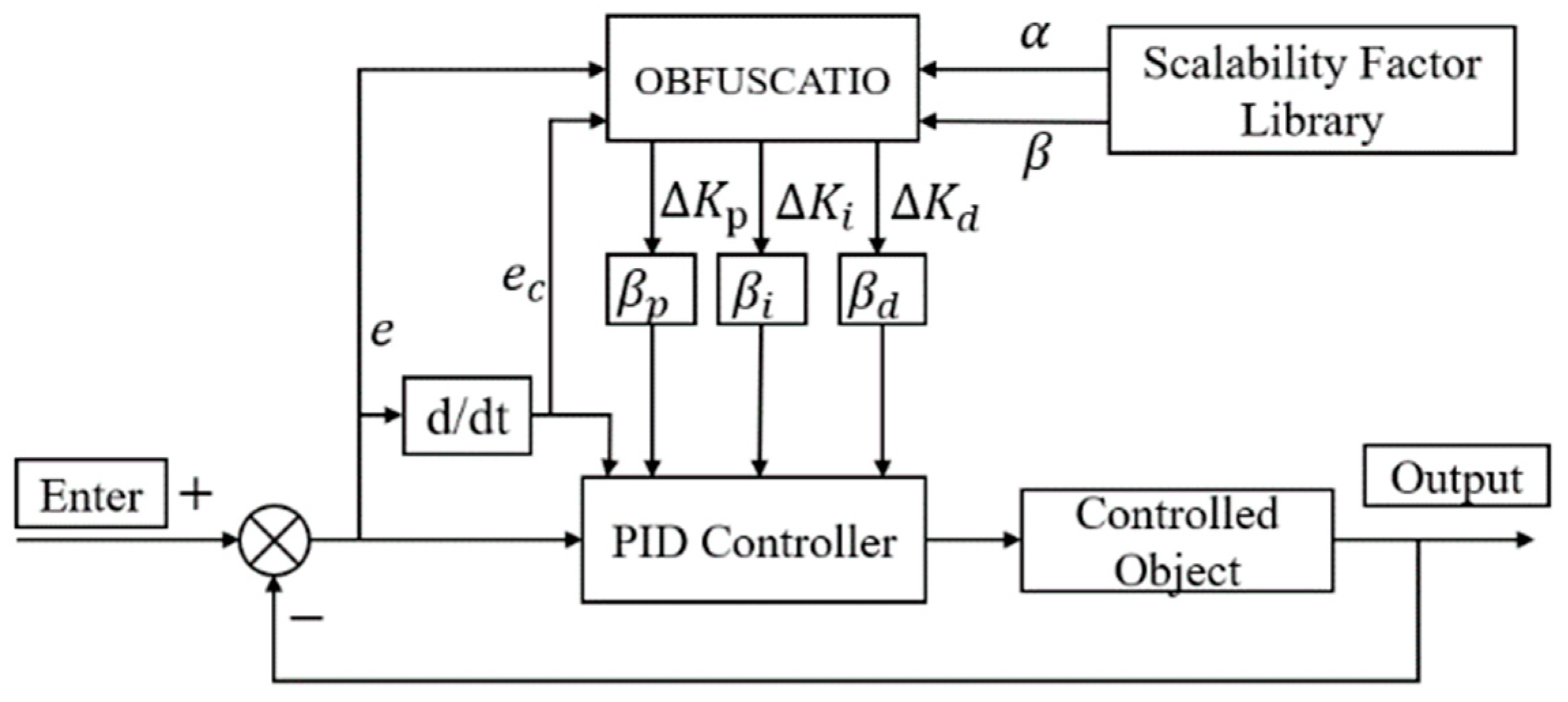
The specific heading control process is shown in Figure 2.

3.2. Design of Variable Universe Fuzzy PID Controller

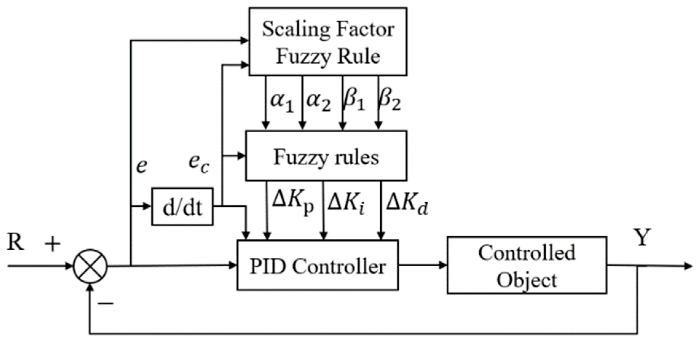
Variable domain fuzzy control is a combination of fuzzy control and the variable domain concept [25]. Changes in input cause the domain range to vary dynamically without changing the control rules. Variable domain fuzzy control may adjust the domain in response to input changes; for example, the domain may expand when the input increases or contract when the input decreases. This contrasts with conventional fixed-domain fuzzy control systems, which struggle to maintain optimal results in the face of outside disturbances. This dynamic change enhances the system’s control effects, stability, and anti-interference capabilities. Figure 3 shows the structural diagram for the variable domain fuzzy PID.
Assuming that the system error is e ( t ) and the rate of change of the error is e ˙ ( t ) , the dynamic change of the control input u ( t ) is affected by the domains U x ( t ) and U y ( t ) , which are adjusted as time t changes, as shown in Formula (18) [26]:
U x t = k x t · U x 0 ,   U y t = k y ( t ) · U y 0
where U x 0 and U y 0 are the initial domains of input and output, respectively, and k x ( t ) and k y ( t ) are the scaling factors that change dynamically with the error.
The scaling factors k x ( t ) and k y ( t ) can be defined as Formula (19):
k x t = 1 + α x · e t E m a x β , k y t = 1 + α y · e t E m a x γ
This setting causes the domain to automatically expand when the error is large and shrink when the error is small, improving the control accuracy [27]. Among these are the adjustment coefficients α x and α y , the exponential parameters of the nonlinear transformation β and γ , and the maximum value of error, E m a x .
Since each output is related to the input but independent of each other, this controller is called “dual-input single-output”. Figure 4 shows the dual-input single-output scaling factor fuzzy criterion for PID control.
Since the domain adjustment of the error and the error change rate is only related to their respective changes, the fuzzy rules of the expansion factors α 1 and α 2 can be more precisely determined, as indicated in Table 1 [28]. The controller’s output variables α 1 and α 2 have a domain range of [ 0 , 1 ] , and its fuzzy variables can be separated into “B, M, S, ZO”.
In the dual-input single-output fuzzy PID controller, the domain of the output variables of the expansion factors β 1 and β 2 is [ 0 , 1 ] , and the fuzzy variables can be divided into “VB, B, M, S, VS” [29].
As shown in Table 2 and Table 3, the fuzzy variables in the dual-input single-output fuzzy PID controller can be categorized as “VB, B, M, S, VS”, and the domain of the output variables of the expansion factors β 1 and β 2 is [ 0 , 1 ] [30,31].
By improving the variable domain of the fuzzy PID controller, a dual-input single-output variable domain fuzzy PID heading controller is designed [15,32]. The simulation results of the traditional PID and fuzzy PID are compared to analyze the anti-interference and stability performance of the variable domain fuzzy PID controller under interference and non-interference conditions.
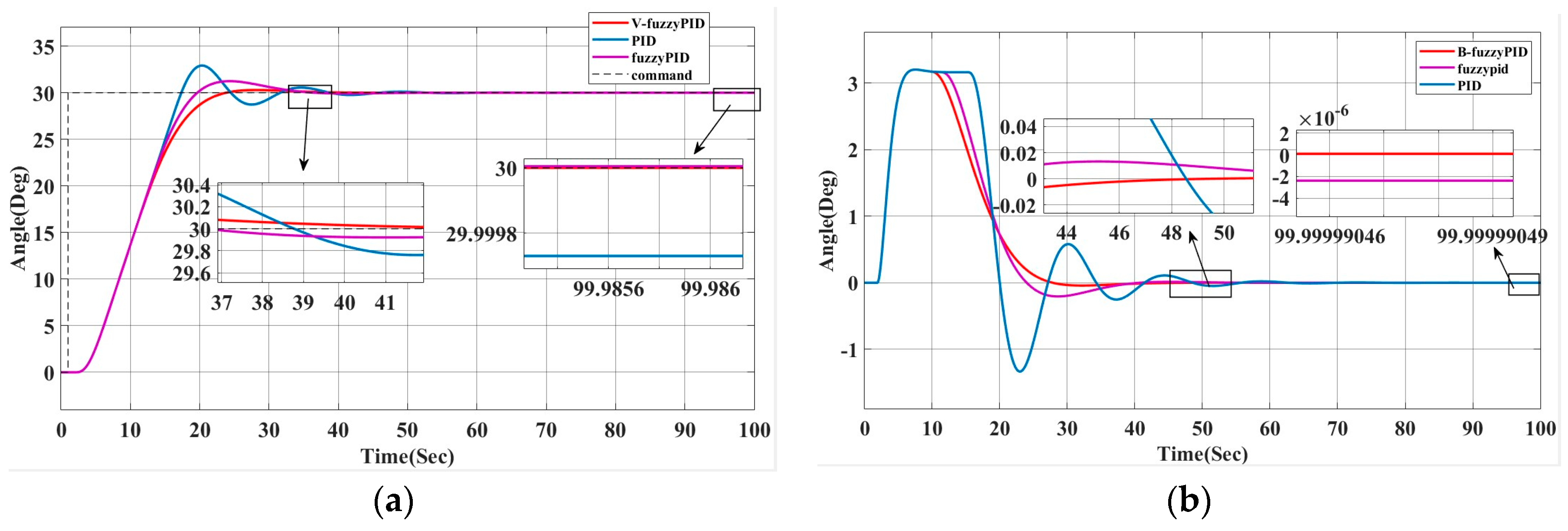
The initial heading angle is set to 0°. For simulation analysis, 30° is selected as the target heading of the unmanned ship. In the absence of interference, the response results of the system are shown in Figure 5a,b, and the specific data are shown in Table 4.
The autonomous ship will be impacted by interference from the wind, waves, and currents during real navigation. Figure 6 shows how these interferences are approximated using white noise and a second-order wave transfer function to simplify the simulation process.
According to Table 4, the system can smoothly track the target heading in a shorter stabilization time after using the variable universe fuzzy PID controller (B-fuzzyPID), with an overshoot of 0.9% and an almost zero steady-state error. Compared with the traditional PID, the B-fuzzyPID reduces the overshoot (from 9.7% to 0.9%) and shortens the stabilization time, although the rise time increases slightly. Figure 6 illustrates how well the improved heading control system performs under interference conditions, while maintaining a smaller overshoot and higher stability in interference environments, such as wind, waves, and currents. Figure 5b and Figure 6b demonstrate that the enhanced system recovers better, has much less interference impact, and is more stable when the rudder angle varies. Usually, the new heading controller offers more precise and dependable control effects due to its larger blocking ability as well as its faster adjustment time.

4. BAS-PSO-SA Algorithm Design

This study develops a hybrid approach based on beetle whiskers (BAS), particle swarm optimization (PSO), and simulated annealing (SA) to further enhance the parameters of the fuzzy PID controller. By using the enhancing benefits of all three, the hybrid algorithm accomplishes balanced optimization on both a global and local level. By methods like dynamic step size adjustment, adaptive learning factor, and temperature reduction strategy the algorithm significantly boosts search performance and optimization efficiency.

4.1. Improved Beetle Whiskers Search Algorithm (BAS)

The Beetle Antennae Search (BAS) algorithm replicates the beetle’s use of their two whiskers to detect their surroundings and look for food [15]. The traditional BAS algorithm updates the search position using a set step size and direction vector; nevertheless, this easy search technique is vulnerable to local optimality in global optimization. In order to achieve this, this study presents a gradient-based data search process and a dynamic step size adjustment mechanism.
(1)
Variable step size design
d t = d 0 · e x p   ( λ · t )
λ = λ m i n + λ m a x λ m i n · f b e s t f t f b e s t f w o r s t + ϵ
In Formula (20), d 0 is the initial step size, λ is the step size decay rate, and t is the current number of iterations [33]. In Formula (21), λ m a x and λ m i n are the maximum and minimum values of the step size, respectively; f b e s t and f w o r s t are the optimal and worst objective functions of the current population, respectively [34]; f t is the objective function value of the current individual; and ϵ is a small value with a replication denominator of zero, set to 10−6.
(2)
Left and right position updates
In each iteration, the beetle compares the fitness value by detecting the left and right positions, and selects the better side as the new position update direction. Its calculation Formula (22) is as follows:
X L = X + d 2 · b , X R = X d 2 · b
where b is a random direction vector, X L and X R represent the positions on the left and right, respectively.
(3)
Formula (23) for updating the position
X m a x = X s t e p · b · s i g n f X L f X R
By calculating the fitness values of the left and right positions and comparing their sizes, the longicorn selects a better direction to update the position.

4.2. Improved Particle Swarm Optimization (PSO)

Particle Swarm Optimization (PSO) gradually approaches the optimal solution by guiding the individual historical optimal solution and the global optimal solution [35]. This paper improves PSO, mainly by including the introduction of adaptive inertia weight and dynamic learning factor.
(1)
Adaptive inertia weight
The size of the inertia weight w dictates the algorithm’s search approach [36]. The dynamically varying inertia weight of Formula (24) is used in this study to balance the two:
w t = w m a x ( w m a x w m i n ) t m a x · t
where w m a x and w m i n are the maximum and minimum inertia weights, t m a x is the maximum number of iterations, and t is the current number of iterations.
(2)
Dynamic learning factor
The learning factors c 1 and c 2 are used to control the guiding ability of the individual optimal solution and the global optimal solution, respectively. In order to enhance the adaptability of the algorithm, this paper adopts the mechanism of Formulas (25) and (26), dynamically adjusting the learning factor [37]:
c 1 t = c 1 s t a r t + c 1 e n d c 1 s t a r t · t t m a x
c 2 t = c 2 s t a r t + c 2 e n d c 2 s t a r t · t t m a x
c 1 s t a r t and c 2 s t a r t are the initial values, c 1 e n d and c 2 e n d are the final values, and t m a x represents the maximum number of iterations of the algorithm.
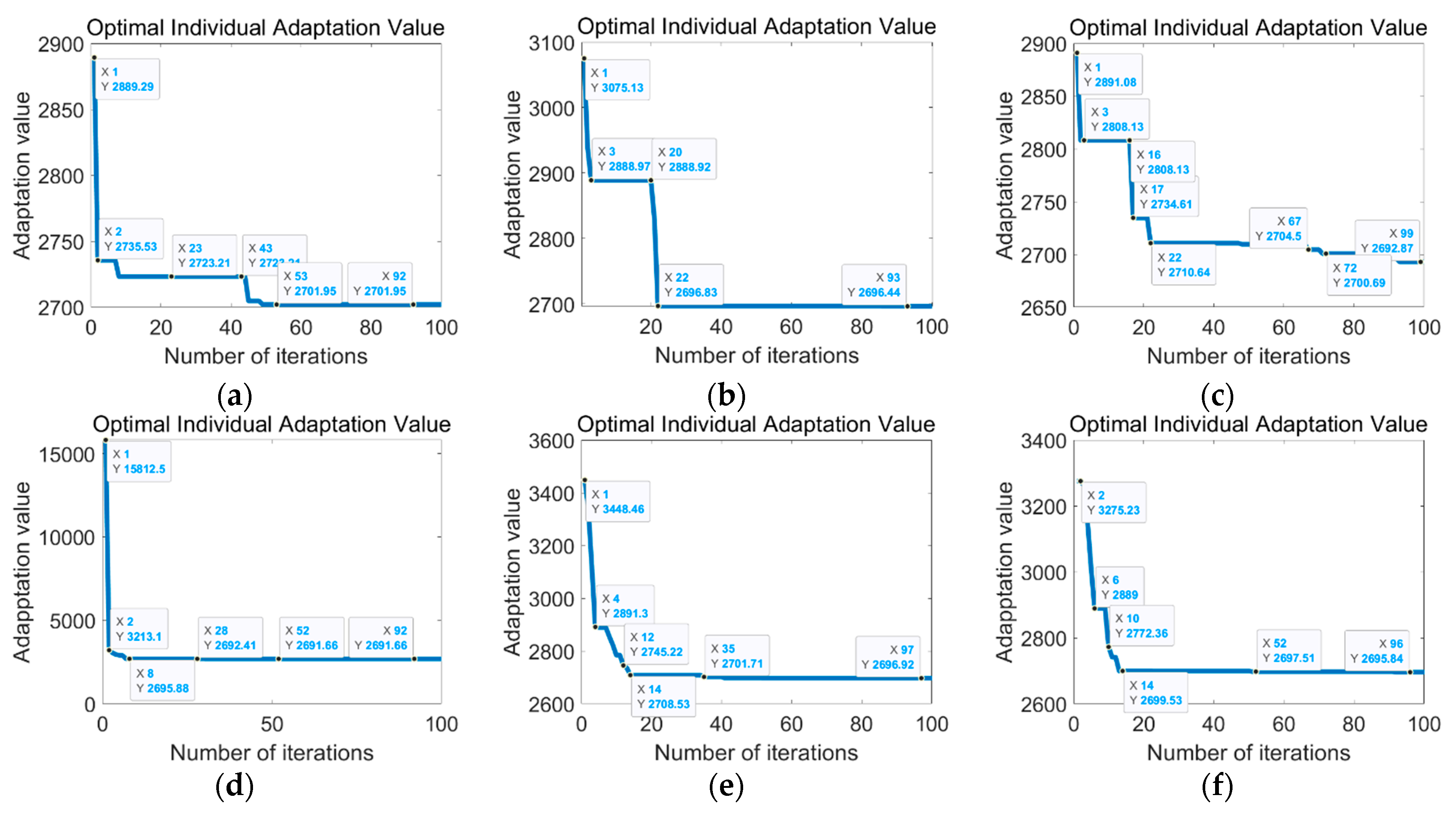
According to Figure 7 and Table 5, the improved algorithm is integrated into the model, and three learning variables based on linear descent and random weights are introduced to generate tabular data. Six different iterative fitness value curves, overshoots, and response times are obtained from the simulation data. The results show that the combination of asymmetric learning factors and random weights produces the lowest peak overshoot and the shortest scale. In terms of response time, the combination of random weights and compressed learning factors reaches the fastest stable state. Compared with other methods, this combination also provides better response speed and stability.
(3)
Particle velocity update formula
In PSO, the position of the particle is adjusted by the velocity update Formula (27):
V i t + 1 = w t · V i t + c 1 t · r 1 · p B e s t i X i t + c 2 t · r 2 · ( g B e s t i X i t )
where, V i t represents the velocity of the i -th particle at time t , r 1 and r 2 are random numbers, p B e s t i is the individual optimal position, and g B e s t i is the global optimal position [38].

4.3. Simulated Annealing Algorithm (SA)

In order to prevent the algorithm from falling into the local optimum, this paper introduces the simulated annealing (SA) mechanism. SA jumps out of the local optimum by accepting certain suboptimal solutions. Its core lies in the design of annealing probability:
(1)
Acceptance probability
The probability P of simulated annealing accepting a worse solution is given by the following Formula (28):
P = e x p   ( f X n e w f X b e s t T )
where f X n e w is the fitness value of the current solution, f X b e s t is the fitness value of the current optimal solution, and T is the current temperature.
(2)
Temperature decay
The temperature T gradually decreases with the number of iterations, and its decay formula is as follows (29):
T ( t + 1 ) = α · T ( t )
where α is the temperature attenuation coefficient, which is usually between 0.8 and 0.99. Choosing a decay coefficient between 0.8 and 0.99 ensures that the algorithm strikes a balance between exploration and exploitation. A higher α value ensures that in the early stages, the algorithm has enough temperature to accept poor solutions, thereby avoiding premature convergence to the local optimum; a lower α value ensures that in the later stages the temperature drops rapidly, the algorithm gradually stabilizes, and concentrates near the global optimal solution [39].

4.4. Dynamic Upper and Lower Bound Adjustment Mechanism

In order to enhance the adaptability of the search, this paper introduces a dynamic upper and lower bound adjustment mechanism based on the change of the optimal solution. When the optimal solution has not been significantly improved within a certain number of iterations, the algorithm automatically adjusts the upper and lower bounds to expand or reduce the search space. The adjustment formulas are as follows ((30) and (31)):
U b t + 1 = z b e s t + U b t L b t α
L b t + 1 = z b e s t U b t L b t α
where U b t and L b t are the upper and lower bounds of the current iteration step t , α is the adjustment factor, and z b e s t is the current global optimal solution.
Through these improved designs, the hybrid algorithm proposed in this paper has stronger global search capabilities and faster convergence speed when dealing with fuzzy PID controller parameter optimization. At the same time, the introduction of the dynamic step size, learning factor, annealing temperature, and other mechanisms makes the algorithm more adaptable and robust.

4.5. Algorithm Simulation Experiment

4.5.1. Algorithm Testing

To verify the effectiveness of the H-BAS, three classic test functions are taken as examples, as shown in Table 6, in order to analyze and compare the effects of the algorithm [40]. Moreover, the test results are compared with the ACO [41], BA [42], GRO [43], Se-PSO [44], DRL, and ANFC algorithms. The Rastrigin function is selected as an example for repeated testing to avoid the lack of diversity in the algorithm and prove its effectiveness.
Table 6 provides a thorough assessment of the optimization algorithm’s performance in tough, multi-modal, and simple unimodal conditions utilizing these three test functions. It can be guaranteed that the chosen optimization algorithm can demonstrate strong performance in a range of circumstances by employing common test functions like Rastrigin, Griewank, and Sphere, as shown in Figure 8. This increases the algorithm’s applicability and efficacy in real-world conditions.
The following are the data of the average best fitness value (Avg) and the standard deviation of the best fitness value (SD) of each algorithm under three test functions, after 500 iterations, respectively, as shown in Table 7.
As shown in Table 7, BAS-PSO-SA consistently outperforms the other algorithms in all three test functions (Rastrigin, Griewank, and Sphere) in terms of both mean best fitness values and standard deviations. This demonstrates its robustness and effectiveness in handling a wide range of optimization problems, from complex multimodal functions to simple unimodal functions. ACO and Se-PSO perform well but are less consistent than BAS-PSO-SA. BA, GRO, DRL, and ANFC have higher mean values and larger standard deviations, indicating that they are less reliable in achieving the optimal solutions for different test functions. These results confirm that the selected optimization algorithm (BAS-PSO-SA) is very effective and applicable to a range of practical optimization problems.

4.5.2. Simulation Analysis

A number of alternative methods are shown and contrasted using variable domain fuzzy heading control in order to demonstrate the optimization algorithm’s superiority. This comparison not only shows the optimization algorithm’s ability to prevent interference under various interference conditions, but it also thoroughly assesses the system’s response time, stability, and control accuracy, demonstrating the algorithm’s efficacy in challenging settings. We perform simulated tests on the heading control of unmanned ships using Simulink on the MATLAB R2022a platform. In the experiment, the “Lanxin” was an unmanned ship, and Table 8 below displays the data from that ship. The Nomoto model, with parameters K = 0.71 and T = 0.32 , is used in the control model.
The simulation time is set to 100 s and the sampling step is 0.1 s. Through the simulation experiment, we will compare and analyze the result data to obtain the response curve, error curve, and rudder angle change data, respectively.
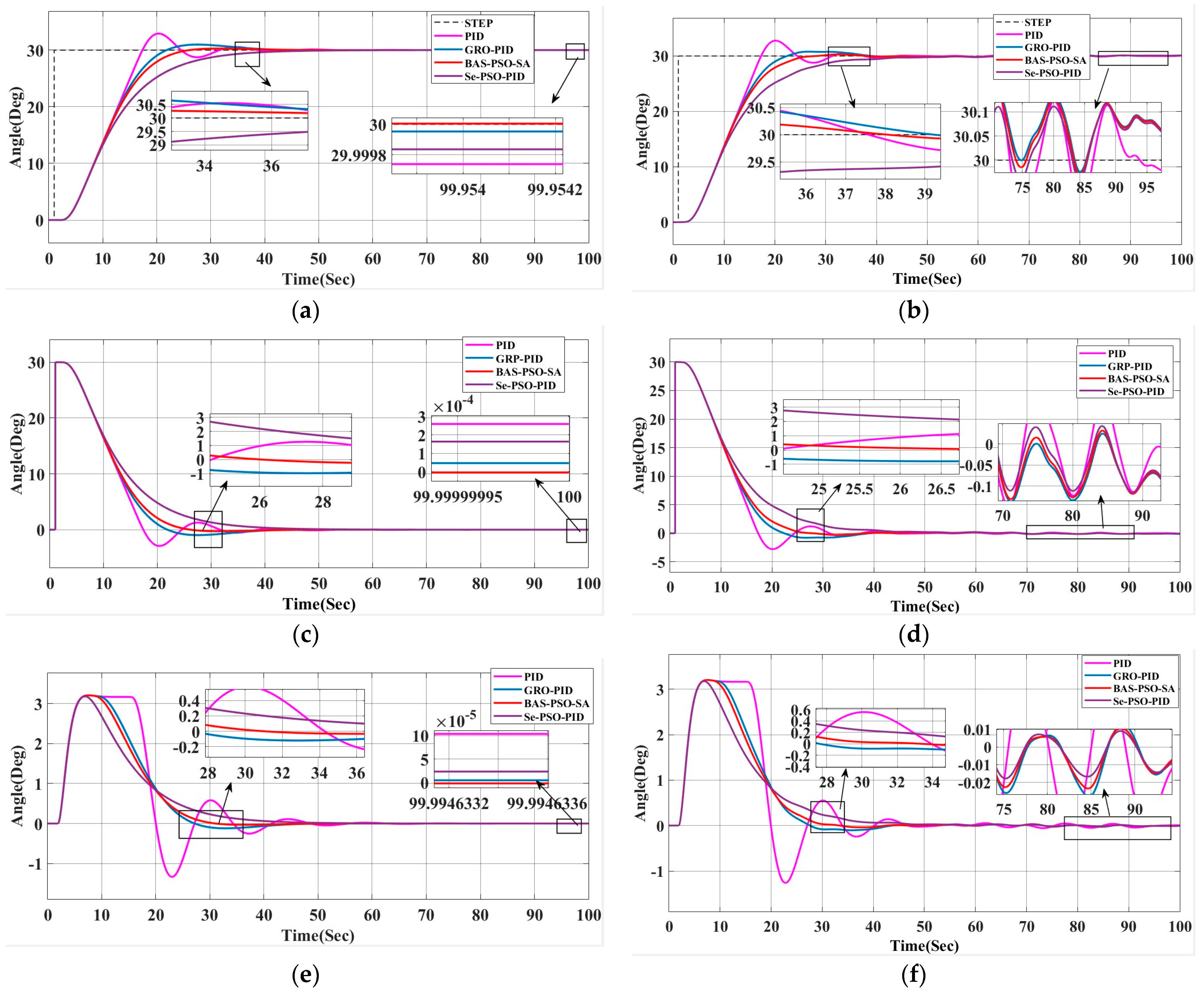
Based on the data in Figure 9 and Table 9 and Table 10, the BAS-PSO-SA-optimized fuzzy PID outperforms traditional PID, GRO-optimized fuzzy PID, and Se-PSO-optimized fuzzy PID. It demonstrates better control balance, moderate steering time, shorter adjustment and stabilization time, and minimal rudder angle stability. The BAS-PSO-SA algorithm significantly reduces overshoot, flipping action, and optimization iterations by 30%, showcasing superior heading accuracy and control efficiency, making it ideal for high-precision systems. Additionally, under disturbances, BAS-PSO-SA exhibits stronger anti-interference capability, smoother and more precise rudder angle changes, accurate target heading tracking with smaller rudder angles, reduced steering wear, and ensures smoother sailing.
In order to further verify the performance of the algorithm, the target heading was adjusted to 60°, and simulation analysis was carried out under interference conditions, such as wind, waves, and currents, as shown in Figure 10 [45]. The process of heading change and rudder angle change was focused on.
Figure 10b shows the change curve of the heading angle under interference at a target heading of 60°, and it can be seen from Table 11 that although the target heading has changed, the hybrid beetle optimization algorithm still shows the best control effect. Compared with other methods, BAS-PSO-SA has the smallest overshoot and the fastest response speed. It is the most balanced in steering time, adjustment time, stabilization time, and stable rudder angle. It can effectively cope with interference, such as wind, waves, and currents, and maintain high control accuracy and stability, which fully proves the system’s strong anti-interference ability and higher robustness under interference conditions. This algorithm is suitable for complex control environments that require high heading accuracy and fast response.
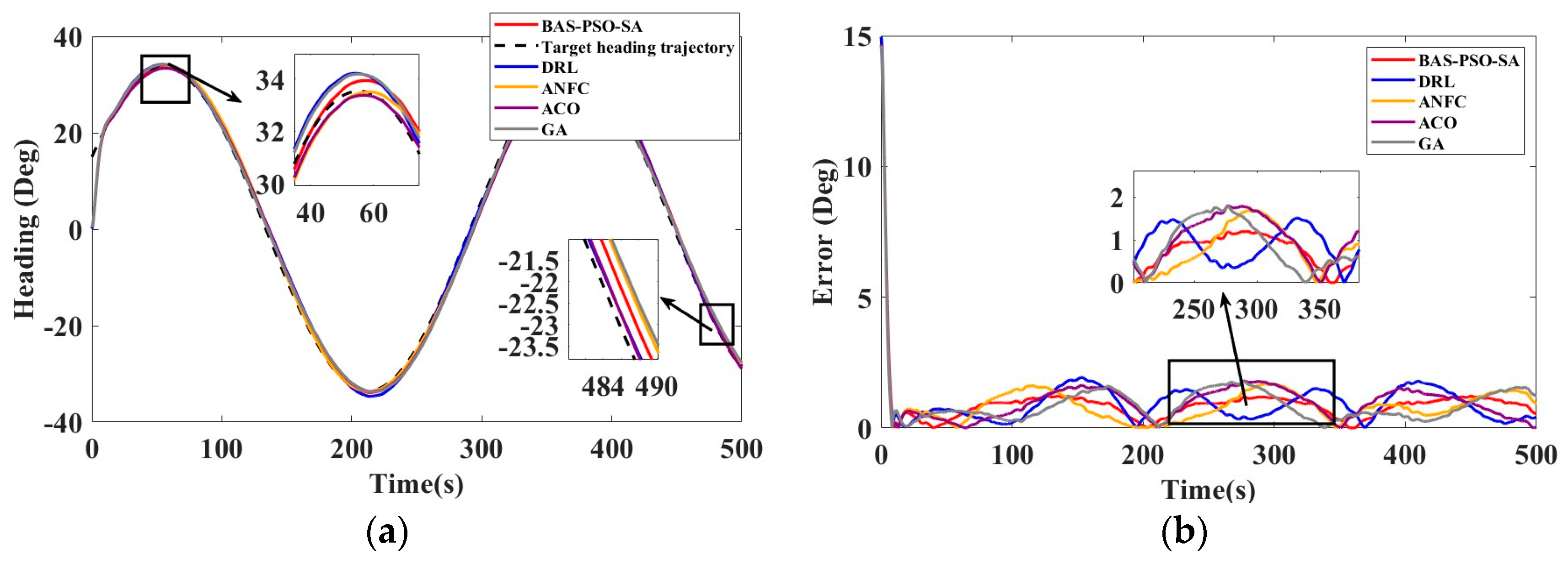
This study evaluates the performance of five control algorithms—BAS-PSO-SA, DRL, ANFC, ACO, and GA—for path tracking under varying ship dynamics and ITTC sea conditions. Three ship types (small, medium, and large) were tested using an S-curve path, with ITTC sea conditions simulating real-world disturbances like wind and waves. Key metrics, ITAE and IAE, were used to assess steady-state error, dynamic response, and robustness. The path tracking and error curves were analyzed to compare algorithm adaptability and performance across ship types and interference conditions.
The experimental ship in this article is ship type 1 “Blue Signal”, the S-type path tracking experiment is shown in Figure 11 and Table 12.
The second vessel, designated as ship type 2, represents the world’s pioneering intelligent unmanned system mother ship. Developed under the leadership of the Guangdong Provincial Laboratory of Southern Marine Science and Engineering, this project was a collaborative effort involving the 708th Institute of China Shipbuilding Industry Corporation and other partners. Named “ZhuHai Yun”, the vessel measures 88.5 m in length, 14 m in width, and 6.1 m in depth, with a displacement of around 2000 tons. It achieves a top speed of 18 knots and operates efficiently at an economic speed of 13 knots [46,47]. The effect of use is shown in Figure 12, and the indicator comparison is shown in Table 13.
Ship type 3 was jointly developed by Harbin Engineering University and Shenzhen HiSpeed Boat Company and named “TianXing No. 1”. It has a total length of 12.2 m, a full load displacement of 7 tons, a maximum speed of over 50 knots, and adopts a low hull design [48,49]. The effect of use is shown in Figure 13, and the indicator comparison is shown in Table 14.
The experimental results show that the BAS-PSO-SA algorithm performs best in the S-shaped path tracking of three different ship types (small ship type 1, large mother ship type 2, high-speed boat type 3). Its IAE and ITAE indicators are significantly lower than those of the DRL, ANFC, ACO, and GA algorithms, and it shows stronger robustness and anti-interference ability under ITTC sea condition interference.

4.5.3. Experimental Setup and Procedure

To validate the proposed self-tuning VUF-PID control framework with hybrid BAS-PSO-SA optimization, a series of experiments were conducted under both simulated and real-world conditions. The experimental setup included a 1.22 m unmanned surface vehicle (USV) equipped with a rudder control system, a GPS module for position tracking, and an inertial measurement unit (IMU) for heading and angular velocity measurements.
The USV used in the experiment is 1200 mm (length). The hull weighs 9 kg and has a maximum payload of 30 kg. When fully loaded, the draft of the USV is 10 cm. The maximum speed of the USV can reach 7 m/s. It is driven by an electric brushless motor with a maximum power of 700 W and a maximum speed of 7000 rpm. The USV can be controlled via 2.4 GHz radio, 4G network or bridge communication. It supports multiple satellite systems including BDS, GPS, GLONASS, Galileo, SBAS, and QZSS with 432 channels. The inertial measurement unit (IMU) operates at an update rate of 200 Hz, providing high-frequency data for precise navigation.
The USV was initialized at the starting position with a heading angle of 0°. The target heading was set to 30° in the first set of experiments and 60° in the second set of experiments. The BAS-PSO-SA algorithm was experimentally compared with the current mainstream deep learning algorithm (DRL) and the adaptive fuzzy neural network algorithm (ANFC). During each experiment, the heading angle, rudder angle, and position of the USV were recorded at a frequency of 10 Hz using the onboard GPS and IMU sensors.
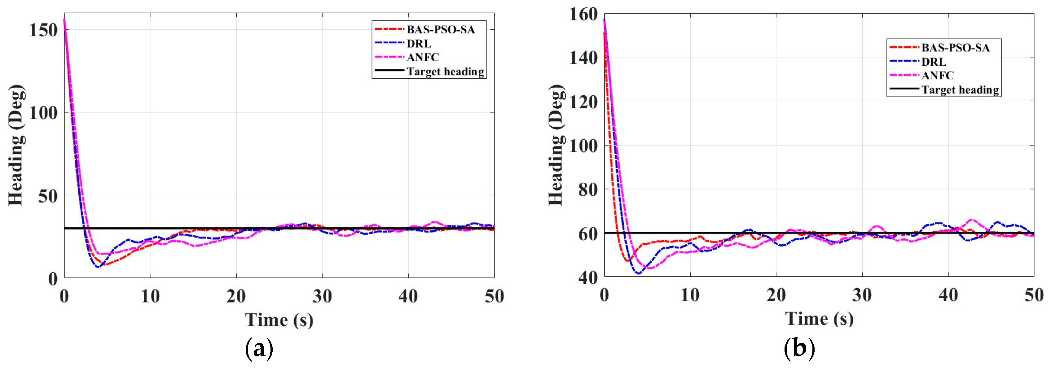
The experimental area is in Jingsi Lake, Lianyungang City, as shown in Figure 14a, and the experimental unmanned surface vessel is shown in Figure 14b, the red frame is the experimental area. The results of the heading ship experiment are shown in Figure 15a,b, and its control performance indicators are shown in Table 15.
Through experimental verification, the self-adjusting VUF-PID control framework based on the BAS-PSO-SA optimization algorithm proposed in this paper shows significant advantages in the unmanned ship heading control. Experimental results show that the BAS-PSO-SA algorithm is superior to the traditional DRL and ANFC algorithms in terms of control accuracy, dynamic response speed, and robustness. The BAS-PSO-SA optimization algorithm has significant advantages in the unmanned ship heading control, and can achieve high precision, fast response, and strong robustness control effects, which is suitable for unmanned ship autonomous navigation tasks in complex marine environments.

5. Conclusions

This study proposes a self-tuning heading control framework for unmanned surface vehicles (USVs) by integrating a variable universe fuzzy PID controller with a hybrid BAS-PSO-SA optimization algorithm, achieving enhanced robustness, precision, and energy efficiency in dynamic marine environments. The framework introduces three key innovations: a dynamic weight adaptation mechanism with asymmetric learning factors to accelerate optimization, a variable universe mechanism to improve disturbance rejection and stability, and a parallel computation architecture to balance global exploration and local refinement. Extensive simulations validate the system’s ability to maintain precise heading control under wind and wave disturbances while complying with IMO standards, demonstrating significant improvements in both control accuracy and energy efficiency compared to conventional methods. Current limitations, such as simplified hydrodynamic modeling and computational latency in high-dimensional scenarios, will be addressed in future work through 6-DOF CFD-validated dynamics, FPGA-accelerated real-time optimization, and multi-objective frameworks targeting sub-0.1° heading accuracy with reduced energy consumption, ultimately advancing autonomous navigation systems for complex maritime operations.

Author Contributions

Conceptualization, H.Z. and Z.Z.; Methodology, Z.Z., Y.W. and Y.L.; Software, H.Z. and Z.Z.; Validation, Z.Z. and W.W.; Formal analysis, Y.W., Y.L. and W.W.; Investigation, Z.Z., Y.W. and Y.L.; Resources, H.Z. and Z.Z.; Data curation, Y.W., Y.L. and W.W.; Writing—draft preparation, Z.Z.; Writing—review and editing, H.Z. and Z.Z.; Visualization, Y.W. and Y.L.; Supervision, H.Z. and Z.Z. All authors have read and agreed to the published version of the manuscript.

Funding

This research received no external funding.

Institutional Review Board Statement

Not applicable.

Informed Consent Statement

Not applicable.

Data Availability Statement

Part or all of the data, models, or code generated or used during the study may be obtained from the corresponding authors upon request.

Acknowledgments

The authors would like to thank the editors and all the reviewers for their valuable comments and suggestions, which have helped improve the quality of our work.

Conflicts of Interest

The authors declare no conflicts of interest.

References

  1. Zhang, H.; Tao, Y.; Zhu, W. Global Path Planning of Unmanned Surface Vehicle Based on Improved A-Star Algorithm. Sensors 2023, 23, 6647. [Google Scholar] [CrossRef]
  2. Mu, D.; Li, J.; Wang, G.; Fan, Y. Research on path following control of unmanned ship based on fast wave inversion disturbance compensation and preset performance. Ocean Eng. 2024, 304, 117864. [Google Scholar] [CrossRef]
  3. Mou, T.; Shen, Z.; Zheng, Z. Adaptive Sliding Mode Trajectory Tracking Control of Unmanned Surface Vessels Based on Time-Domain Wave Inversion. J. Mar. Sci. Eng. 2024, 12, 1278. [Google Scholar] [CrossRef]
  4. Zhang, S.; Xiang, X.; Yang, S. Cooperative control system of multi-ASV: Design and implementation. In Proceedings of the 2018 IEEE 8th International Conference on Underwater System Technology: Theory and Applications (USYS), Wuhan, China, 1–3 December 2018; pp. 1–6. [Google Scholar]
  5. Zhao, Z.; Lei, D.; Chen, J.; Li, H. Optimal control of mode transition for four-wheel-drive hybrid electric vehicle with dry dual-clutch transmission. Mech. Syst. Signal Process. 2018, 105, 68–89. [Google Scholar] [CrossRef]
  6. Huang, H.; He, C.; Wang, H. Variable-Domain Fuzzy PID Control Strategy for Magnetic Resonance Pulsed Power Supplies. In Proceedings of the 17th Annual Conference of China Electrotechnical Society, Beijing, China, 17–18 September 2023; pp. 1213–1222. [Google Scholar] [CrossRef]
  7. Yin, Z.; Wang, R.; Ma, X.; Su, R. Fractional-Order PIλDμ Control to Enhance the Driving Smoothness of Active Vehicle Suspension in Electric Vehicles. World Electr. Veh. J. 2024, 15, 184. [Google Scholar] [CrossRef]
  8. Joseph, S.B.; Dada, E.G.; Abidemi, A.; Oyewola, D.O.; Khammas, B.M. Metaheuristic algorithms for PID controller parameters tuning: Review, approaches and open problems. Heliyon 2022, 8, e09399. [Google Scholar] [CrossRef]
  9. Du, H.; Liu, P.; Cui, Q.; Ma, X.; Wang, H. PID Controller Parameter Optimized by Reformative Artificial Bee Colony Algorithm. J. Math. 2022, 2022, 3826702. [Google Scholar] [CrossRef]
  10. Lu, W.; Gao, Y. Variable Universe Fuzzy Adaptive PID Control in the Digital Servo System. In Proceedings of the 2016 8th International Conference on Intelligent Human-Machine Systems and Cybernetics (IHMSC), Hangzhou, China, 27–28 August 2016; pp. 204–207. [Google Scholar]
  11. Wu, X.; Pan, Y.; Wang, G.; Hou, L. Pitch motion suppression of electric vehicle active suspensions based on multibody dynamics. Mech. Mach. Theory 2024, 198, 105667. [Google Scholar] [CrossRef]
  12. Pan, L.; Zhao, D.; Li, L.; Lin, J. Bio-Inspired Computing: Theories and Applications. In Proceedings of the 18th International Conference, BIC-TA 2023, Changsha, China, 15–17 December 2023. Revised Selected Papers, Part I. [Google Scholar]
  13. CSEI: International Conference on Computer Science, Electronics and Industrial Engineering (CSEI). Advances and Applications in Computer Science, Electronics and Industrial Engineering. In Proceedings of the Conference on Computer Science, Electronics and Industrial Engineering (CSEI 2022), Ambato, Ecuador, 14–18 November 2022. [Google Scholar]
  14. Deng, Z.; Li, H. Proceedings of the 2015 Chinese Intelligent Automation Conference: Intelligent Automation Processing; Springer: Berlin/Heidelberg, Germany, 2015; Volume 337. [Google Scholar]
  15. Xu, C.; Xu, F.; Sun, F.; Zhang, X.; Jin, J.; Luan, B.; Oka, K. Research on an Intelligent Control Method of a Magnetic Actuator for Micro Electrical Discharge Machining. Actuators 2022, 11, 371. [Google Scholar] [CrossRef]
  16. Yuanqiang, Z.; Shi, G.; Liu, H.; Li, W. Decision supporting for ship collision avoidance in restricted waters. Int. J. Simul. Process Model. 2020, 15, 40. [Google Scholar] [CrossRef]
  17. Li, K.; Xue, Y.; Cui, S.; Niu, Q.; Yang, Z.; Luk, P. Advanced Computational Methods in Energy, Power, Electric Vehicles, and Their Integration. In Proceedings of the International Conference on Life System Modeling and Simulation, LSMS 2017 and International Conference on Intelligent Computing for Sustainable Energy and Environment, ICSEE 2017, Nanjing, China, 22–24 September 2017. Part III. [Google Scholar] [CrossRef]
  18. Mishra, P.; Panigrah, S.; Das, S.; Dept, M.; Milit, P. Ships Steering Autopilot Design by Nomoto Model. Int. J. Mech. Eng. Robot. (IJMER) 2015, 3, 2321–5747. [Google Scholar]
  19. Zhang, L.; Xiao, L.; Jin, Z. Fuzzy PID Control Simulation Research on Rotational Speed Regulation for Diesel Engines. In Proceedings of the 2015 International Conference on Mechatronics, Electronic, Industrial and Control Engineering, Shenyang, China, 1–4 April 2015. [Google Scholar] [CrossRef]
  20. Karthik, T.; Srinivasulu, P.; Seshadri, G. Modified Pi-Pd Controller for Avoiding Overshoot in Temperature of Barrel Heating System. Int. J. Eng. Res. Technol. 2014, 3, 611–614. [Google Scholar]
  21. Aydoğdu, Ö.; Levent, M. Trajectory Control of a Variable Loaded Servo System by using Fuzzy Iterative Learning PID Control. Int. J. Eng. Sci. Comput. 2016, 6, 3628–3634. [Google Scholar]
  22. Ji, G.; Li, S.; Feng, G.; Wang, H. Enhanced Variable Universe Fuzzy Control of Vehicle Active Suspension Based on Adaptive Contracting–Expanding Factors. Int. J. Fuzzy Syst. 2023, 25, 2986–3000. [Google Scholar] [CrossRef]
  23. Liang, H.; Dong, Y.; Cao, D. Research on VSC-HVDC double closed loop controller based on variable universe fuzzy PID control. In Proceedings of the 2017 China International Electrical and Energy Conference (CIEEC), Beijing, China, 25–27 October 2017; pp. 633–638. [Google Scholar]
  24. Ji, G.; Zhang, L.; Shan, M.; Zhang, J. Enhanced variable universe fuzzy PID control of the active suspension based on expansion factor parameters adaption and genetic algorithm. Eng. Res. Express 2023, 5, 035007. [Google Scholar] [CrossRef]
  25. Xing, S.; Chen, S.; Wei, Z.; Xia, J. Unifying Electrical Engineering and Electronics Engineering. In Proceedings of the 2012 International Conference on Electrical and Electronics Engineering, London, UK, 4–6 July 2012; Volume 238. [Google Scholar]
  26. Wang, Y.; Postolache, O.; Xu, W.; Ye, S.; Ni, D.; Zhong, M. Fuzzy Sliding Mode Synchronous Control of Double-Container for Overhead Crane; IEEE: Piscataway, NJ, USA, 2019; pp. 1–7. [Google Scholar] [CrossRef]
  27. Jiang, L. Proceedings of the 2011 International Conference on Informatics, Cybernetics, and Computer Engineering (ICCE2011) November 19–20, 2011, Melbourne, Australia; Springer: Berlin/Heidelberg, Germany, 2011. [Google Scholar]
  28. Zhao, J.; Hua, M.; Liu, T. Research on a Sliding Mode Vector Control System Based on Collaborative Optimization of an Axial Flux Permanent Magnet Synchronous Motor for an Electric Vehicle. Energies 2018, 11, 3116. [Google Scholar] [CrossRef]
  29. HeRu, S.; Wei, W. Electric Short-Term Load Forecasting Using Artificial Neural Networks and Fuzzy Expert System. In Proceedings of the 2011 International Conference on Informatics, Cybernetics, and Computer Engineering (ICCE2011), Melbourne, Australia, 19–20 November 2011. [Google Scholar]
  30. Tipsuwanpom, R.; Runghimmawan, T.; Intajag, S.; Krongratana, V. Fuzzy logic PID controller based on FPGA for process control. In Proceedings of the 2004 IEEE International Symposium on Industrial Electronics, Ajaccio, France, 4–7 May 2004; Volume 1492, pp. 1495–1500. [Google Scholar]
  31. Ma, C.; Huang, B.; Basher, M.K.; Rob, M.A.; Jiang, Y. Fuzzy PID Control Design of Mining Electric Locomotive Based on Permanent Magnet Synchronous Motor. Electronics 2024, 13, 1855. [Google Scholar] [CrossRef]
  32. Jia, Y.; Du, J.; Zhang, W. Proceedings of 2017 Chinese Intelligent Systems Conference: Volume II; Springer: Singapore, 2018. [Google Scholar] [CrossRef]
  33. Wang, L.; Wu, Q.; Liu, J.; Li, S.; Negenborn, R.R. Ship Motion Control Based on AMBPS-PID Algorithm. IEEE Access 2019, 7, 183656–183671. [Google Scholar] [CrossRef]
  34. Jiao, L.; Zhao, J.; Wang, C.; Liu, X.; Liu, F.; Li, L.; Shang, R.; Li, Y.; Ma, W.; Yang, S. Nature-Inspired Intelligent Computing: A Comprehensive Survey. Research 2024, 7, 0442. [Google Scholar] [CrossRef]
  35. Zhang, X.; Li, H.; Zhang, W.; Lopes, A.M.; Wu, X.; Chen, L. Improved Parameter Identification for Lithium-Ion Batteries Based on Complex-Order Beetle Swarm Optimization Algorithm. Micromachines 2023, 14, 413. [Google Scholar] [CrossRef]
  36. Hu, H.; Li, H.; Liang, G.; Zhao, L.; Yang, J.; Wei, X. Phase-Only Pattern Synthesis for Spaceborne Array Antenna Based on Improved Mayfly Optimization Algorithm. Electronics 2023, 12, 895. [Google Scholar] [CrossRef]
  37. Xiao, Z.; Hou, B.; Ning, J.; Lin, B.; Liu, Z. Collision Avoidance for Unmanned Surface Vehicles in Multi-Ship Encounters Based on Analytic Hierarchy Process–Adaptive Differential Evolution Algorithm. J. Mar. Sci. Eng. 2024, 12, 2123. [Google Scholar] [CrossRef]
  38. Tian, S.; Li, Y.; Kang, Y.; Xia, J. Multi-robot path planning in wireless sensor networks based on jump mechanism PSO and safety gap obstacle avoidance. Future Gener. Comput. Syst. 2021, 118, 37–47. [Google Scholar] [CrossRef]
  39. Yuting, L.; Yuyou, L.; Qiaozi, P.; Yingzhe, W. Improvement review and parameter exploration of simulated annealing algorithm. Univ. Math. 2015, 31, 419–426. [Google Scholar]
  40. Cortez, R.; Garrido, R.; Mezura-Montes, E. Spectral Richness PSO algorithm for parameter identification of dynamical systems under non-ideal excitation conditions. Appl. Soft Comput. 2022, 128, 109490. [Google Scholar] [CrossRef]
  41. Dorigo, M.; Birattari, M.; Stutzle, T. Ant colony optimization. IEEE Comput. Intell. Mag. 2006, 1, 28–39. [Google Scholar] [CrossRef]
  42. Du, X.; Zhang, M.; Sha, G. Research on Fuzzy Adaptive PID Fuzzy Rule Optimization Based on Improved Discrete Bat Algorithm. In Proceedings of the 16th International Conference of Web Information Systems and Applications, WISA 2019, Qingdao, China, 20–22 September 2019; Proceedings 16. pp. 662–674. [Google Scholar]
  43. Wu, G. Application of adaptive PID controller based on bacterial foraging optimization algorithm. In Proceedings of the 2013 25th Chinese Control and Decision Conference (CCDC), Guiyang, China, 25–27 May 2013; pp. 2353–2356. [Google Scholar]
  44. Shami, T.M.; El-Saleh, A.A.; Alswaitti, M.; Al-Tashi, Q.; Summakieh, M.A.; Mirjalili, S. Particle Swarm Optimization: A Comprehensive Survey. IEEE Access 2022, 10, 10031–10061. [Google Scholar] [CrossRef]
  45. Mu, D.; Li, J.; Wang, G.; Fan, Y. Disturbance rejection control of adaptive integral LOS unmanned ship path following based on fast wave inversion. Appl. Ocean Res. 2024, 144, 103907. [Google Scholar] [CrossRef]
  46. Qingqing, X. The world’s first intelligent unmanned system scientific research mother ship “Zhuhai Cloud” was delivered for use. Pearl River Water Transp. 2023, 22–23, 1672–8912. [Google Scholar] [CrossRef]
  47. Southern Marine Science and Engineering Guangdong Laboratory (Zhuhai). “Zhuhai Cloud”: The world’s first intelligent unmanned system scientific research mother ship. J. Sun Yat-Sen Univ. (Nat. Sci. Ed.) (Chin. Engl.) 2023, 62, 187. [Google Scholar]
  48. Wang, X.; Song, X.; Du, L. Review and Application of Unmanned Surface Vehicle in China. In Proceedings of the 2019 5th International Conference on Transportation Information and Safety (ICTIS), Liverpool, UK, 14–17 July 2019; pp. 1476–1481. [Google Scholar]
  49. Jing, L. The world’s fastest unmanned boat “Tianxing No. 1” is launched. Ocean Fish. 2018, 8, 46–47. [Google Scholar]
Figure 1. Setting fuzzy rules according to fuzzy logic: (a) fuzzy rule K p of parameter; (b) fuzzy rule K i of parameter; (c) fuzzy rule K d of parameter.
Jmse 13 00558 g001
Figure 2. Unmanned ship heading control process.
Jmse 13 00558 g002
Figure 3. Variable universe fuzzy PID structure diagram.
Jmse 13 00558 g003
Figure 4. A schematic diagram of the fuzzy heading control structure of an unmanned ship with a variable domain.
Jmse 13 00558 g004
Figure 5. Simulation results of variable universe fuzzy PID heading control under interference-free conditions (a) heading comparison and (b) rudder angle change comparison.
Jmse 13 00558 g005
Figure 6. Simulation results of variable universe fuzzy PID heading control under disturbance conditions (a) heading comparison and (b) rudder angle change comparison.
Jmse 13 00558 g006
Figure 7. Fitness curve of particle swarm with different inertia weights and learning factors. (a) Linear decreasing inertia weight adds shrinkage factor (LS-PSO); (b) linear decreasing inertia weight adds synchronous learning factor (LL-PSO); (c) linear decreasing inertia weight adds asymmetric learning factor (LA-PSO); (d) random weighting adds shrinkage factor (RS-PSO); (e) random weighting adds synchronous learning factor (RL-PSO); and (f) random weighting adds asymmetric learning factor (RA-PSO).
Jmse 13 00558 g007
Figure 8. Comparison of algorithms after 500 iterations on three test functions: (a) comparison of algorithms after 500 iterations on Rastrigin; (b) comparison of algorithms after 500 iterations on Griewank; and (c) comparison of algorithms after 500 iterations on Sphere.
Jmse 13 00558 g008
Figure 9. Comparison of the heading control simulation of an unmanned ship with a target heading of 30° under non-interference and interference conditions using different algorithms. (a) Response curve under non-interference condition; (b) response curve under interference condition; (c) error curve under non-interference condition; (d) error curve under interference condition; (e) heading angle change curve under non-interference condition; and (f) heading angle change curve under interference condition.
Jmse 13 00558 g009
Figure 10. Comparison of different algorithms for simulation of unmanned ship heading control with target heading of 60° under non-interference conditions and interference conditions. (a) Response curve under interference conditions and (b) heading angle change curve under interference conditions.
Jmse 13 00558 g010
Figure 11. (a) Algorithm optimization comparison of ship type 1 in S-shaped trajectory tracking experiment and (b) steady-state error of algorithm comparison.
Jmse 13 00558 g011
Figure 12. (a) Algorithm optimization comparison of ship type 2 in S-shaped trajectory tracking experiment and (b) steady-state error of algorithm comparison.
Jmse 13 00558 g012
Figure 13. (a) Algorithm optimization comparison of ship type 3 in S-shaped trajectory tracking experiment and (b) steady-state error of algorithm comparison.
Jmse 13 00558 g013
Figure 14. (a) Experimental unmanned boat and (b) experimental water environment.
Jmse 13 00558 g014
Figure 15. Course change curve of experimental ship. (a) Experimental curve for 30° target heading; (b) Experimental curve for 60° target heading.
Jmse 13 00558 g015
Table 1. Fuzzy rules for scaling factors α 1 and α 2 .
e / e c PBPMPSZONSNMNB
α 1 BMSZOSMB
α 2 BMSZOSMB
Table 2. Fuzzy rules for expansion factor β 1 .
β 1 e c
NBNMNSZOPSPMPB
eNBVBVBVBBBSVS
NMVBVBBBMSVS
NSVBMBSVSSVS
ZOMMSVSSMM
PSVSSVSSBMVB
PMVSSMBBVBVB
PBVSSMBVBVBVB
Table 3. Fuzzy rules for scaling factor β2.
β 2 e c
NBNMNSZOPSPMPB
eNBVSVSSBSVSVS
NMSMMBMMS
NSMMBVBBMS
ZOBBSVBVBBB
PSMMBVBBMM
PMSMMBMMS
PBVSVSSMSVSVS
Table 4. Comparison of different fuzzy controls.
Control Mode Rise Time/sStabilization TimeOvershoot
PID20.345.99.7%
FuzzyPID24.334.14.1%
B-fuzzyPID28.224.10.9%
Table 5. Six response analyses of weights and learning factors.
OvershootPeak TimeStable Time
LS-PSO0.45%100.54 s130.99 s
LL-PSO0.58%100.62 s132.31 s
LA-PSO0.51%99.86 s132.42 s
RS-PSO0.50%99.97 s129.83 s
RL-PSO0.46%100.61 s131.01 s
RA-PSO0.20%99.44 s131.38 s
Table 6. Test functions.
NameFunction Expression
Rastrigin f x = 10 d + i = 1 d x i 2 10 c o s   ( 2 π x i )
Griewank f x = i = 1 d x i 2 4000 i = 1 d c o s   ( x i i ) + 1
Sphere f x = i = 1 d x i 2
Table 7. Comparison of algorithm results after 500 iterations.
Number of Runs ACOBAGROSe-PSOBAS-PSO-SADRLANFC
RastriginAvg18.54128.13522.39918.8693.16113.8556.917
SD3.66212.3575.4425.9221.1954.7922.547
GriewankAvg0.4210.1810.2410.3940.0510.0750.184
SD0.0560.0660.0820.1970.0180.0250.133
SphereAvg1.10004.6517.1391.7910.0072.7190.135
SD0.0001.3750.9180.5470.0020.9770.127
Table 8. Unmanned ship model data.
Boat
Length/m
Boat
Width/m
Boat
Speed/kn
Full Load
Draft/m
Full Load
Displacement/m3
Block
Coefficient
7.022.06350.322.730.6976
Table 9. Comparison of performance indicators of heading control optimized by different algorithms.
Control ModeRise Time/sAdjustment Time/sStabilization Time/sOvershoot
PID20.34824.47745.8539.7%
GRO-PID27.51145.26164.1213.2%
Se-PSO-PID56.30756.30763.9540
BAS-PSO-SA31.43541.20939.0.9%
Table 10. Comparison of heading performance indicators different control algorithms at 30-degree target heading.
Control ModeRise Time/sAdjustment Time/sStabilization Time/sOvershoot
PID15.2819.94056.0920.112
GRO-PID9.82227.39749.9670.0608
Se-PSO-PID7.02454.22262.2840.0427
BAS-PSO-SA8.95531.79143.0960.041
Table 11. Comparison of heading performance indicators different control algorithms at 60-degree target heading.
Control ModeSteering Time/sAdjustment Time/sStabilization Time/sStable Rudder Angle
PID15.21319.94056.8910.1036
GRO-PID10.02227.46358.0230.0581
Se-PSO-PID6.91161.48567.5430.0347
BAS-PSO-SA8.75532.05753.2290.0307
Table 12. Curved path tracking indicators for ship type 1.
Control MethodsBAS-PSO-SADRLANFCACOGA
IEA276.0658336.9147304.2146360.6558306.9027
ITEA3.02973.57933.27023.23333.2833
Table 13. Curve path tracking indicators for ship type 2.
Control MethodsBAS-PSO-SADRLANFCACOGA
IEA454.2776487.0770458.3405508.8080461.3515
ITEA2.52273.08302.71332.74982.7461
Table 14. Curve path tracking indicators for ship type 3.
Control MethodsBAS-PSO-SADRLANFCACOGA
IEA95.2814304.7516217.3322255.7372271.9124
ITEA6.35416.86746.50126.40756.6621
Table 15. Heading control performance indicators.
Control MethodsIEAITEA
30°60°30°60°
BAS-PSO-SA315.30170.461727.021474.70
DRL350.38308.323055.623520.68
ANFC398.00338.813480.343633.33
Disclaimer/Publisher’s Note: The statements, opinions and data contained in all publications are solely those of the individual author(s) and contributor(s) and not of MDPI and/or the editor(s). MDPI and/or the editor(s) disclaim responsibility for any injury to people or property resulting from any ideas, methods, instructions or products referred to in the content.