Abstract
The marine environment is complex and variable, with the absorption and scattering effects of seawater and turbulence causing significant attenuation of received optical signals and introducing random jitter, which limits the communication range and stability of underwater wireless optical communication systems. This paper presents the Superposition UEP-Spinal Code structure, which utilizes unequal error protection (UEP) to adjust the transmission performance of different types of information in underwater composite data communication by adjusting the superposition weighting factors in the encoding algorithm. This encoding method enhances the noise immunity of important data, and with the same bandwidth utilization, the overall decoding complexity is reduced by 13.3% compared to the previously improved Spinal code encoding algorithm. The results show that the Superposition UEP-Spinal Code provides a more stable, reliable, and efficient communication solution for underwater wireless optical communication systems with randomly varying channel conditions.
1. Introduction
The ocean is the largest ecosystem on Earth, harboring abundant resources. To gain a deeper understanding of marine information, it is necessary to construct an ocean observation network through various means such as satellites [1], autonomous underwater vehicles (AUVs) [2], remotely operated vehicles (ROVs) [3], and seafloor observatories [4]. Underwater communication technologies, particularly underwater optical cables, radio frequency, and acoustic communication technologies, are key to ensuring the stable and reliable operation of this system. Underwater communication technologies include underwater optical cables, radio frequency, and acoustic communication. Underwater optical cable communication offers high speed, wide coverage, and low latency but involves high construction and maintenance costs [5]; underwater radio frequency communication achieves high data rates over short distances, but due to significant attenuation in water (the attenuation coefficient of radio waves at 2.4 GHz frequency in seawater is as high as 169 dB/m) and the need for giant antennas, it is primarily used for military submarine communication [6]; and, although underwater acoustic communication performs well in long-distance transmission, its low bandwidth, noise interference, poor information security, and impact on aquatic life limit its application scope [7].
In 1963, Duntley et al. discovered that blue-green light in the wavelength range of 450 nm to 550 nm experiences the least attenuation in water, which led to the development of underwater wireless optical communication (UWOC) technology [8]. Compared to underwater electromagnetic wave communication, the attenuation of optical signals in water is significantly reduced, which helps to increase transmission distance [9]; compared to underwater acoustic communication, this technology can greatly enhance link bandwidth while reducing power consumption, size, and cost [10]. Currently, UWOC has been widely applied in ocean observation networks, effectively improving marine exploration efficiency and underwater operational safety [11]. L. B. Kumar et al. proposed a multi-hop, free-space, optical–underwater wireless optical communication (FSO-UWOC)-integrated system method to address the safe transportation and tracking of cargo and missiles in naval and marine applications [12]. Chaudhary et al. introduced a visible light communication-based polarization division multiplexing (VLC-PDM) technique to tackle the performance issues of UWOC systems under harsh underwater conditions and varying chlorophyll levels [13]. Zhang et al. proposed a hybrid acoustic–optical communication method to solve the problem of autonomous underwater vehicle positioning and tracking control [14]. Yadav et al. developed a UAV (unmanned aerial vehicle) dual-hop hybrid RF (radio frequency)–UWOC (underwater optical communication) system to optimize UAV altitude and communication performance [15]. However, the marine environment is complex and variable. The absorption and scattering effects of seawater can cause severe attenuation of received optical signals, limiting the communication range of underwater wireless optical communication systems. Additionally, ocean turbulence effects can lead to random fluctuations in received optical signals, affecting the stability of underwater wireless optical communication systems.
The incremental transmission mechanism of rateless codes is particularly suitable for scenarios where channel conditions are random or difficult to predict. In this transmission mechanism, the sender does not transmit a fixed number of encoded symbols but adjusts flexibly based on the channel conditions; the receiver, on the other hand, recovers the information by collecting a sufficient number of channel output symbols. Once decoding is successful, the receiver only needs to send a simple feedback signal, and the sender will stop transmission. Among these, Spinal codes, a rateless coding scheme with capacity-achieving properties, were proposed by Jonathan Perry et al. [16]. They employ an innovative coding structure that uses hash functions for encoding and decoding, offering low encoding complexity and excellent performance, making them well suited to adapt to varying channel conditions. Spinal codes perform exceptionally well in both AWGN (Additive White Gaussian Noise) channels and BSC (Binary Symmetric Channel) channels. Theoretical analysis and experimental results have demonstrated that the throughput of Spinal codes approaches the Shannon capacity [17]. Khamy explored the application of Spinal codes in underwater communication in [18], combining them with differential frequency hopping technology to enhance the security and anti-interference performance of underwater communication. This method effectively improves the robustness of underwater communication systems. The application of Spinal codes in massive MIMO systems has also seen development, achieving promising results [19]. Xu proposed a scheme that concatenates Spinal codes with polar codes, significantly enhancing the performance of polar codes by leveraging the sequential encoding characteristics of Spinal codes. In 2022, A. Li conducted an in-depth performance analysis to improve the reliability of Spinal code transmission over fading channels and proposed a self-concatenated coding scheme. This scheme significantly enhances the system’s noise resistance and improves signal transmission quality under harsh channel conditions [20]. However, in Spinal codes, when a frame of symbols contains errors, the erroneous information bits are typically concentrated in the last few symbols [21]. The error rate of the final information block severely impacts the overall error rate of Spinal codes, leading to a degradation in their performance. In [21], a method was proposed to reduce the error rate of the final information block by adding additional tail symbols. However, this approach has limited effectiveness in reducing the overall frame error rate. If multiple tail symbols are added to reduce the error rate, it not only increases transmission overhead but may also result in a lower code rate.
This paper addresses the issue of increased demodulation complexity in Spinal codes when relying on random number generators to enhance noise resistance. It proposes a Superposition UEP-Spinal Code structure, which improves signal noise resistance under low signal-to-noise ratio (SNR) conditions. This structure utilizes unequal error protection (UEP) to transmit data of different priority levels in parallel. By adjusting the elements of the superposition weighting factor P, it optimizes the communication performance of different priority information sources while simplifying the structural complexity of less critical components. Compared to Spinal codes of the same code length, it achieves an average error rate reduction of 23.62%, where the error rate is defined as the number of erroneous bits divided by the total transmitted bits over a given time interval. Meanwhile, it enhances the noise resistance of critical components, achieving an average error rate reduction of 5.04% under the same spectral efficiency. Additionally, the overall decoding complexity is reduced by 13.3%, aiming to provide a more stable, reliable, and efficient communication solution for underwater wireless optical communication with random channel variations.
2. Spinal Code Encoding Algorithm
The Spinal code encoding principle utilizes a hash function and a random number generator (RNG). A series of random numbers can be generated through RNG to generate a continuous sequence of encoded symbols in a sequential encoding manner. Since the symbols mapped by the hash function are entirely independent, if two source messages differ by only one bit before encoding, the transmitted symbols after encoding will also exhibit significant differences. In the Spinal encoding algorithm, there is no strict standard for the length of the hash value, as the hash function used only serves to increase the difference between the encoded blocks of each partition. As a result, Spinal codes possess excellent noise resistance and bit error resilience.
In general, a mapping scheme that maps a data sequence of arbitrary length to a fixed-length sequence is called a hash function. The output of a hash function is referred to as a hash value, hash code, or hash state, among other terms. The mapping performance of a hash function is mainly influenced by the output’s independence and randomness characteristics. Regardless of the application, it is desirable for a hash function to provide fully independent and randomly distributed outputs for different inputs. The form of the hash function used in rateless Spinal codes is as follows:
where both parameters k and v are positive integers.
For any input and , as well as any random number generated by a random seed, the hash function h can produce an independent and equally probable binary sequence of length v. For another input and , where , the following holds:
where m refers to the input data, which are the data to be hashed and can typically be any length of message, text, or file. The hash function generates a fixed-length hash value based on this input data. s is the salt, a randomly generated value that is usually combined with the original data before hashing to ensure the uniqueness of the generated hash value. and .
To ensure that information can be correctly recovered by the receiver in rateless transmission, the length v of the hash state must be sufficiently large or even infinite, thereby enabling the generation of an infinite number of channel input symbols. However, in practical applications, constrained by computational and storage capabilities, achieving an infinite v is infeasible. To address this issue, an RNG can be incorporated before directly mapping the hash state to channel input symbols. This RNG uses a shorter hash-generated sequence as a seed to produce a sufficiently long binary random sequence. Subsequently, a channel mapping function is applied to obtain a sufficient number of channel input symbols. The channel input sequence is then transmitted iteratively to the receiver until successful decoding and feedback confirmation are achieved. Each transmission pass consists of symbols from the sequence in their corresponding order. For example, during the first pass, the transmitter sends symbols , where denotes the first element of the sequence .
The channel mapper is responsible for converting the c-bit binary number b generated by the random number generator (RNG) into a signal suitable for channel transmission. For BSC (Binary Symmetric Channel) and BEC (Binary Erasure Channel), c = 1 and can be chosen. This means that the single bit produced by the mapper is directly transmitted as the channel input to the receiver. For the AWGN channel, the mapper can employ either truncated Gaussian mapping or uniform mapping.
where , and is the inverse of the CDF of a standard normal variable. Here, , where β determines the truncation range, limiting the mapped results to the interval , and P is the average power of the transmitted signal. When the parameter β and c approach infinity, the symbols generated by the truncated Gaussian mapping function are equivalent to a Gaussian signal with power P.
For uniform mapping in the AWGN channel, the output symbol is
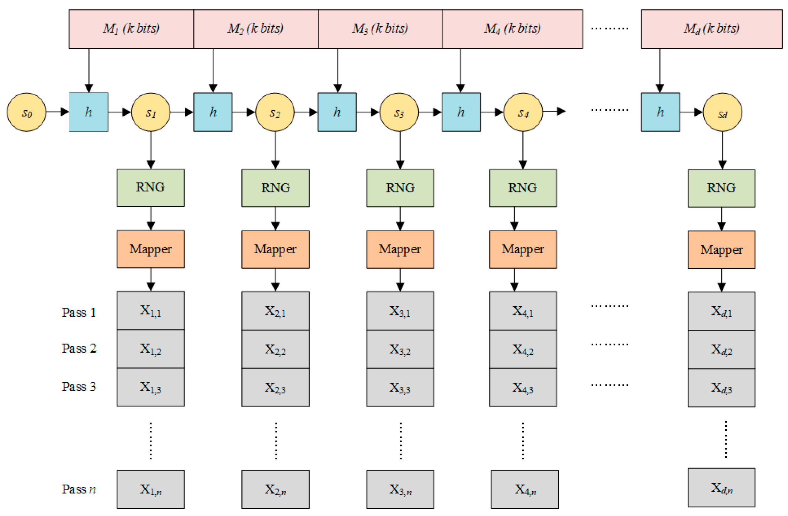
Figure 1 provides a block diagram of the rateless Spinal code encoder. The encoding process of Spinal codes can be divided into the following steps:
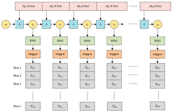
Figure 1.
Spinal code encoder.
Step 1: The n-bit information sequence is uniformly divided into d non-overlapping blocks, each containing k-bits. Thus, the total number of blocks is d = n/k, and the partitioned sequence is .
Step 2: The sender and receiver are initialized with the same hash function value . The d information segments are sequentially fed into the hash function according to the following equation:
This generates d new hash states, as follows: .
Step 3: Based on each node state value Si where i∈{1,2,…, d}, the encoder invokes the RNG to generate a series of c-bit binary sequences.
Step 4: All the generated bit sequences are input into the mapper, which maps them into a series of numerical values. This sequence constitutes the channel input symbols, and the encoded symbol sequence is . The numerical sequence generated in the l-th pass is denoted as , where represents the l-th element of the sequence . The transmitter stops sending encoded packets upon reaching this information; i.e., no further packets are added.
3. Superposition UEP-Spinal Code Algorithm Encoding Principle
This paper proposes an innovative superimposed Spinal code structure aimed at enhancing the protection of header information in Spinal codes through an unequal error protection mechanism. Given that certain parts of data in a file are more critical than others during data transmission—for instance, in MPEG video streams, I-frames, as key frames, are far more important than P-frames and thus require stricter protection—we have designed an encoding scheme with UEP characteristics.
Assume that the k source blocks of the file to be transmitted are divided into r distinct subsets, namely S1, S2,…, Sr, and the sum of these subsets satisfies the following condition: |S1| + |S2| + |Sr| = k. Suppose that for any i < j, the data blocks in the i-th subset are of higher importance than those in the j-th subset. In this paper, we assume r = 2, meaning the source blocks are divided into two main categories: one subset containing more important blocks (MIBs) and another containing relatively less important blocks (LIBs). Assume that the first k source blocks belong to MIBs, while the remaining k′ (where 1 < k′ < k) source blocks fall into LIBs. When using an encoding scheme with UEP properties, even if errors occur during data transmission, the data blocks in MIBs will be successfully decoded before those in LIBs. This design ensures priority protection for critical data during transmission, significantly improving data transmission reliability and efficiency.
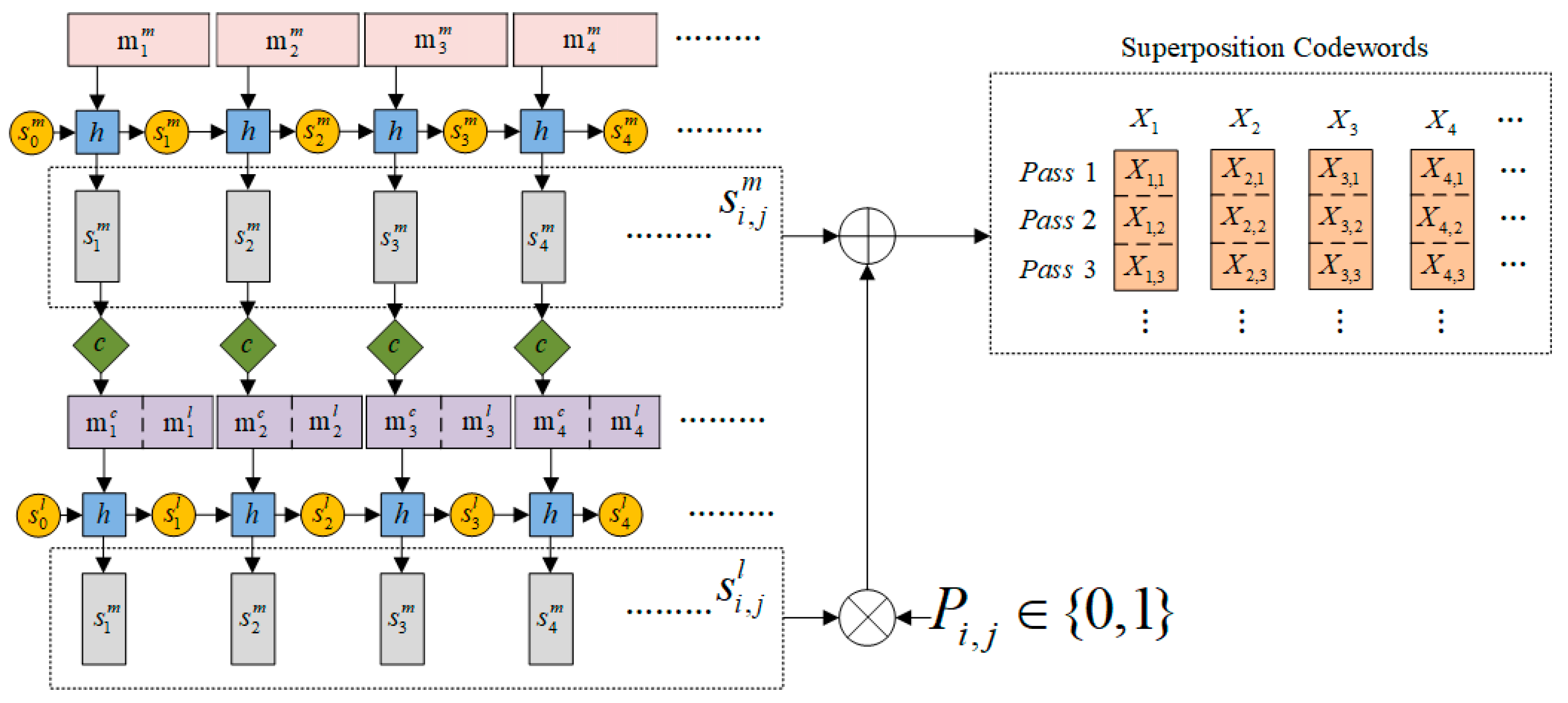
For the more important data, additional error-checking codes are generated, while the encoding structure for less important parts is simplified. The tail code decoding in this scheme has fewer layers and a simpler structure compared to traditional Spinal codes, enhancing accuracy. Compared to Spinal codes with the same bandwidth utilization, the proposed scheme improves the reliability of signal transmission in low-SNR conditions by focusing on MIB. The encoding process of the Superposition UEP-Spinal Code is illustrated in Figure 2 and consists of four steps:
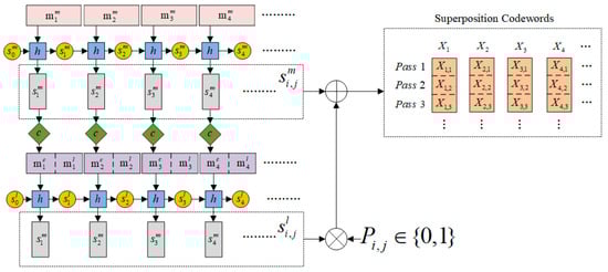
Figure 2.
Schematic diagram of the Superposition UEP-Spinal code.
Step 1: Divide the original data to be encoded into two parts. The initial portion of the data (header code) is classified as MIBs, while the remaining data (tail code) are classified as LIBs. In the Superposition UEP-Spinal encoding algorithm, the division of MIBs and LIBs can be adjusted according to the requirements of the transmission task. Then, during the subsequent block partitioning process, the encoding algorithm divides both MIBs and LIBs into non-overlapping blocks of size d. If the length of the last block is insufficient to reach d, padding data will be added to meet the length requirement, ensuring that all blocks are of equal size for easier subsequent processing and transmission. Denote MIBs as and LIBs as .
Step 2: The encoder first uniformly divides into d non-overlapping blocks, with each block containing bits, i.e., . These blocks are then fed into a Spinal encoder with an initial hash state , following the following equation:
Sequentially generating d new hash states of length v, refers to the hash state of length v generated by the i-th MIB information block.
Step 3: The encoder uniformly divides into d non-overlapping blocks, with each block containing bits. The hash state values generated from are error-correction-encoded to produce -bit parity bits . Then, and are rearranged into , where represents a -bit sequence containing information bits from and . Subsequently, the rearranged message is fed into a Spinal encoder with an initial hash state , following the equation
Sequentially generating d new hash states of length v, refers to the hash state of length v generated by the information blocks.
Step 4: The encoder generates the final encoded symbols according to the following equation:
where ⊕ denotes modulo 2 addition operation; ∘ denotes Hadamard product operation; P is a binary matrix containing 0 s and 1 s. is the weight factor matrix of , and the values 0 and 1 in indicate whether contains the information of . The more 0s in P, the higher the proportion of information in X. is the final encoding generated by the MIB and LIB information blocks of the i-th part. The numerical sequence generated in the j-th pass is represented as
After the generation of channel input symbols is completed, the transmitter continuously sends until it receives a successful decoding message from the decoder. Each channel consists of d symbols, and during the l-th channel transmission, the transmitter sends the symbols .
4. Theoretical Complexity Analysis of Superposition UEP-Spinal Code
Let ER and ES represent the encoding complexity after RNG mapping with the Spinal code and the Superposition UEP-Spinal Code, respectively. Similarly, CR and CS denote the decoding complexity after RNG mapping with the Spinal code and the Superposition UEP-Spinal Code, respectively. and represents the bubble complexity of the Spinal code and the Superposition UEP-Spinal Code; The complexity of generating a hash function of length v is , where v is the length of the generated hash function and k is the block length of the original signal input to the hash function. The complexity of mapping to a random sequence of length l through RNG is . Thus, the encoding complexity of the Spinal code after RNG mapping can be derived as follows:
where n is the original signal length. The decoding complexity and recognition time can be expressed as follows:
Among them, is the time required for the hash function to generate a single hash value, B is the number of optimal nodes retained during each decoding, lgB is the complexity of the Fano metric used in decoding, and BF ≤ B represents the number of nodes expanded during decoding, meaning that the maximum number of demodulations for Spinal codes will not exceed B2k. In each layer, decoding ultimately selects the best node from the BF candidate nodes, i.e., the lower bound of TR is
In the encoding of the Superposition UEP-Spinal Code, the original signal is divided into and for encoding; the encoding complexities and for and are the following:
where c is the time complexity of generating the check bits after the hash function generates the hash value for the signal; is the code length of , is the code length of and ; k1 is the block length of , and k2 is the block length of . The total encoding complexity of the Superposition UEP-Spinal Code is
Since the elements in the weight factor matrix P affect the information content of and in the final encoding, thereby influencing the protection effectiveness of the transmitted and and the number of nodes expanded during decoding, the number of demodulation expanded nodes for and for will vary depending on the elements in P. The decoding complexities and for and in the Superposition UEP-Spinal Code are, respectively
The total decoding time is
Among them, and represent the decoding times for and , respectively, and represent the time required to generate a single hash value using the hash function for and , and both and do not exceed the number of retained optimal nodes B. The lower bound of is
Next, the decoding complexity of the two encoding schemes will be compared by contrasting the decoding times of Spinal codes and Superposition UEP-Spinal Codes. To more intuitively compare the theoretical decoding times, this paper will unify some encoding parameters for Spinal codes and Superposition UEP-Spinal Codes, thereby simplifying the equations.
Simplification 1: Since different hash functions require different times to generate a single hash value, to avoid the impact of the hash function on the comparison of decoding complexity between Spinal codes and Superposition UEP-Spinal Codes, the same hash function is selected for hash value calculation, i.e., .
Simplification 2: In Superposition UEP-Spinal Codes, the complexity and generation time of the check bits for vary depending on the method used. To facilitate comparison with Spinal codes, the check bits for are generated using RNG mapping, meaning l and c have the same complexity (l = c). To calculate the relationship between the code lengths of Superposition UEP-Spinal Codes and Spinal codes, the ratio of the original information quantities of and is set to 2:1, i.e., .
Simplification 3: In Superposition UEP-Spinal Codes, the division length of the original information for and directly affects the amount of information contained in each hash value, thereby influencing the number of expanded nodes. By setting the division length of the original information for and to be the same , the amount of information contained in each hash value can be ensured to be the same, facilitating the control of the number of decoding expanded nodes in Simplification 3.
Simplification 4: Adjustments to the weight factor matrix P can alter the transmission performance of and , thereby affecting the number of decoding expanded nodes. Therefore, the weight factor matrix P is fixed to be all ones, meaning the protection properties for and are the same. Combined with Simplification 3, it can be inferred that the number of decoding expanded nodes is the same, i.e., .
Based on the above simplifications, it can be calculated that c = 3v/2, and the code length of the Superposition UEP-Spinal Codes Ls = 4nv/(3k). This means that a Spinal code of the same length needs to generate random numbers l = 4v/3 through RNG mapping. The decoding times for Spinal codes and Superposition UEP-Spinal Codes of the same length can be simplified from Equations (12) and (20), as follows:
The lower bounds of the two are
It is not difficult to see that there will be a difference in decoding time between the two lower bounds of . The difference in decoding complexity will further increase with the length of the hash function v and the number of expanded nodes BF.
5. Simulation Verification
The simulation is conducted under an AWGN channel with the following parameters: n = 48, k1 = k2 = 8, D = 2, v = 32, . The Spinal code uses the one-at-a-time hash function for mapping. The error correction coding for employs an RNG based on LFSR (Linear Feedback Shift Register). The method for generating the parity bits of is consistent with Simplification 2 in line 331 of the theoretical complexity analysis, where the parity bits are dynamically generated based on the random number generator mapping. The modulation uses Minimum Shift Keying (MSK), and the demodulation employs coherent demodulation, with a symbol rate B = 106; carrier frequency fc = 2 × 10⁶; and initial symbol phase φ = 0. Given that the system enters an ineffective decoding region (with the error rate approaching the random guessing probability) when the SNR is below −14 dB, and that the error rate converges as the channel conditions improve when the SNR exceeds 0 dB, this experiment selects the SNR range of −14 to 0 dB as the core analysis window. This ensures the interpretability of the dynamic characteristics of the error rate curve within the observed range.
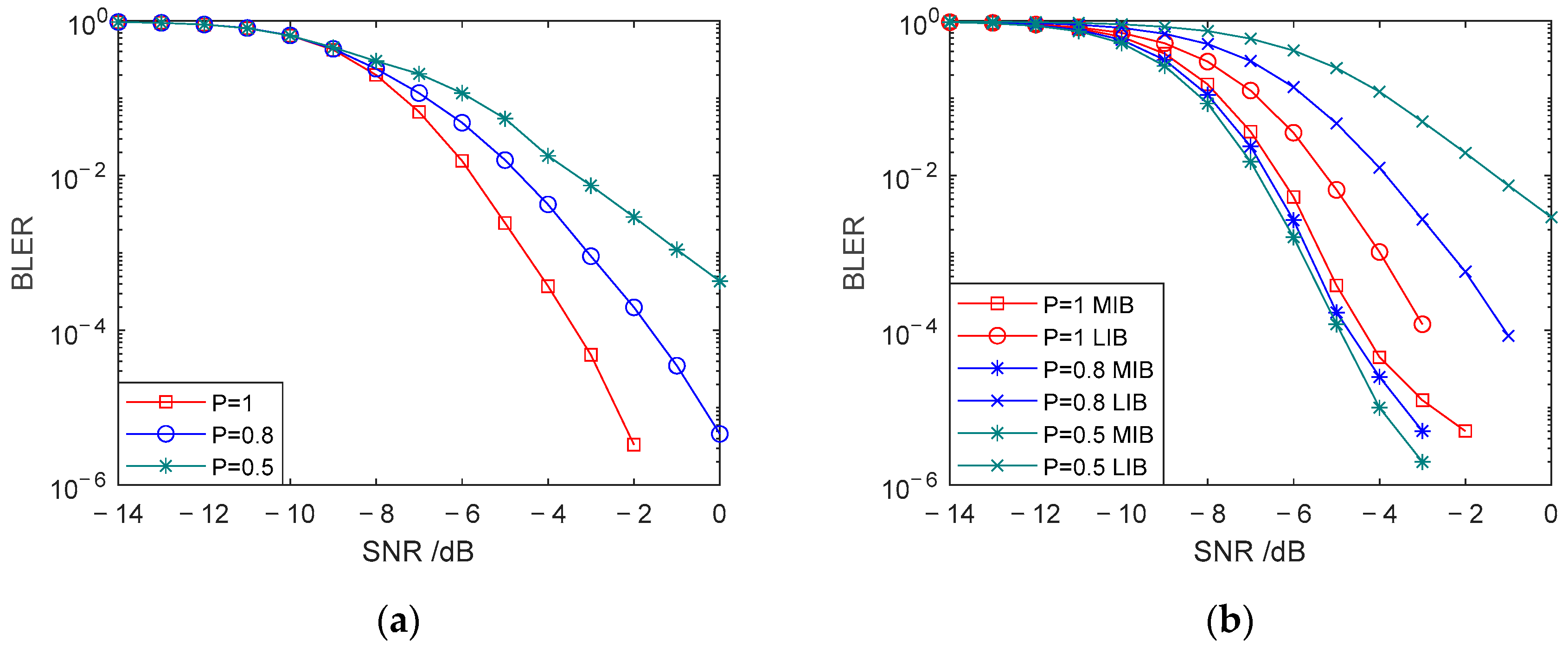
Figure 3 compares the communication performance of the Superposition UEP-Spinal Code when the duty cycle of element 1 in the weighting factor matrix P is set to different values. Figure 3a shows the overall block error rate (BLER) performance comparison when the duty cycle of P is set to 1, 0.8, and 0.5, respectively. The block error rate represents the block-level error probability during data transmission. Figure 3b compares the BLER of MIB information and LIB information under the same duty cycle settings of 1, 0.8, and 0.5. The dynamic allocation of communication performance between MIBs and LIBs is achieved through the parameter configuration of the weight factor matrix P. Simulation results based on multiple sets of different weight factors under AWGN channels show that adjusting the weight distribution of matrix P can effectively regulate the BER differences between MIBs and LIBs, verifying the key role of the weight factor matrix in hierarchical information transmission.
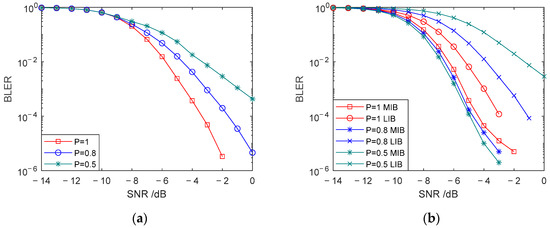
Figure 3.
Comparison of BLER for head and tail codes with different weight factor matrix P. (a) Comparison of communication BLER for different duty cycles. (b) Comparison of BLER for head and tail codes with different duty cycles.
As the duty cycle of P decreases, the proportion of elements in the final encoded data (from encoding step 4) gradually reduces. This sacrifices the communication performance of to enhance the communication performance of . Since part of the data in is reduced, the noise resistance of the tail bits is severely affected. From Figure 3a, it can be seen that as the duty cycle of P decreases, the overall BLER increases. Compared to the case where all elements of matrix P are 1, the average BLER of the encoding with an occupancy ratio of 0.8 increases by , and the average BLER of the encoding with an occupancy ratio of 0.5 increases by over the SNR range of −14 dB to 0 dB under the same SNR conditions. When the duty cycle of P becomes too low, the noise resistance of the tail bits decreases significantly, causing the bit error rate (BER) of the tail bits to rise sharply. The performance sacrificed in LIB information outweighs the performance improvement in MIB information, leading to a rapid increase in overall BLER. From Figure 3b, it can be observed that when the occupancy ratio of P is 0.8, compared to the encoding with an occupancy ratio of 1, the average BLER of MIBs decreases by , while the average BLER of LIBs increases by . When the occupancy ratio of P is 0.5, the average BLER of MIBs decreases by , while the average BLER of LIBs increases by . This indicates that by adjusting the duty cycle of element 1 in the weighting factor matrix P, the communication performance between MIBs and LIBs can be tuned to adapt to different communication scenarios. In cases where the protection of MIB information is prioritized, the duty cycle of P can be appropriately reduced to sacrifice the communication performance of LIB information in exchange for a lower BER for MIB information.
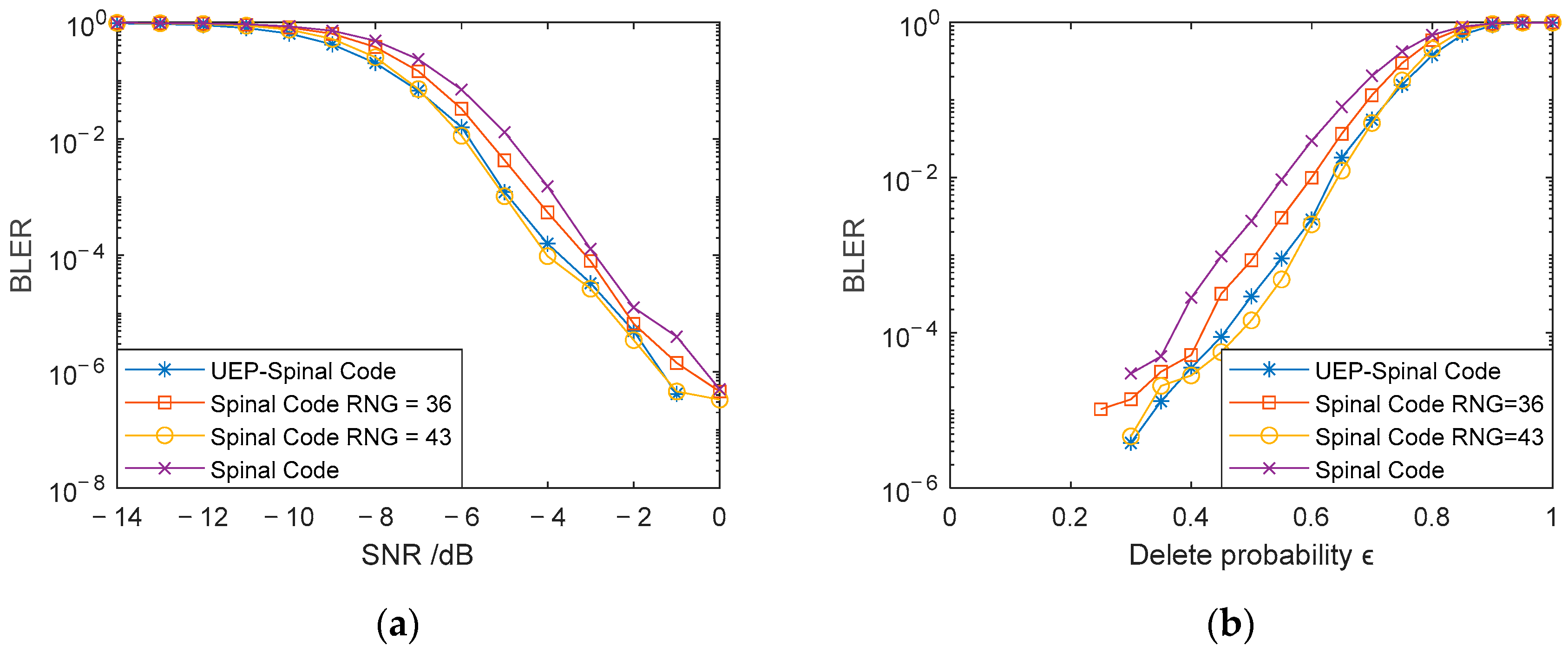
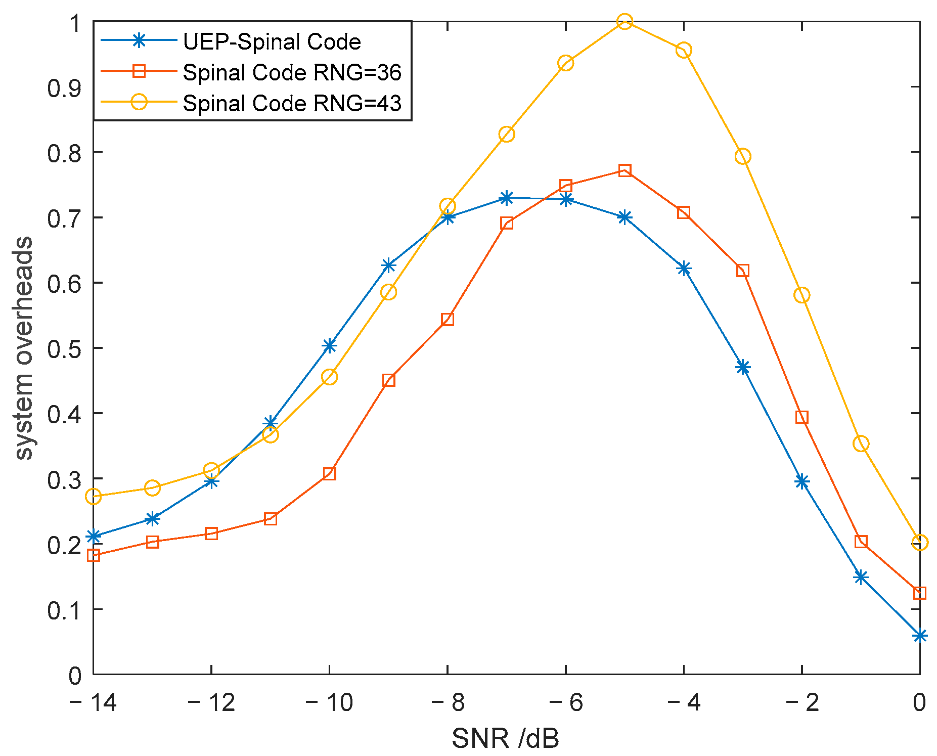
From the simplified complexity analysis formulas (25) and (26), it can be deduced that when the hash length v = 32, the code length of the Spinal code mapped to 43 bits through RNG is the same. Figure 4a presents a comparison of the BLER for the Superposition UEP-Spinal Codes, Spinal codes mapped to 36-bit and 43-bit encoded packets, and Spinal codes without RNG mapping, under AWGN channel conditions with a SNR ranging from −14 dB to 0 dB. Figure 4b shows the BLER comparison for the same four encoding methods in a BEC with a fixed SNR of 0 dB. The duty cycle of the weight factor matrix P in the Superposition UEP-Spinal Codes is set to 1, meaning all elements in matrix P are 1. Figure 5 provides a comparison of the decoding system overhead for Superposition UEP-Spinal Codes and the two mapping-based encoding methods in the AWGN channel. To minimize interference in the comparison, the generated bit data during decoding are normalized, and the normalized bit data are used to compare the system’s decoding overhead. Figure 4, by comparing the BER curves under different channel conditions, proves that the noise resistance of the Superposition UEP-Spinal Code remains at the same level as that of the original Spinal code, indicating that the Superposition UEP-Spinal encoding algorithm does not cause any loss in basic performance. Figure 5’s decoding overhead comparison shows that the Superposition UEP-Spinal encoding algorithm reduces decoding complexity compared to the previous Spinal code encoding algorithm, thereby demonstrating the communication performance optimization effect of the Superposition UEP-Spinal Code.
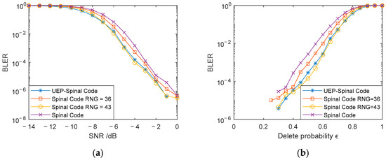
Figure 4.
Comparison of BLER for different encoding methods: (a) AWGN channel, and (b) BEC channel.
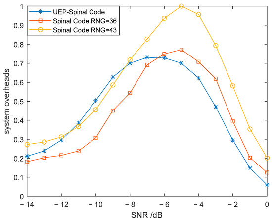
Figure 5.
Comparison of system overheads for different encoding methods.
It is evident that the performance of the Superposition UEP-Spinal Codes in both the AWGN and BEC channels is nearly identical to that of the Spinal code mapped to 43 bits with the same code length. From Figure 4a, it can be observed that in the AWGN channel, the BLER of the Superposition UEP-Spinal Code shows the greatest reduction compared to the Spinal code without RNG mapping at an SNR of −5 dB, with a maximum decrease of 90.64%, and an overall average BLER reduction of . Compared to the Spinal code mapped to a 36-bit encoding packet, the maximum BLER reduction at −5 dB reaches 71.53%, with an overall average BLER reduction of . From Figure 4b, it can be observed that in the BEC channel, the BLER of the Superposition UEP-Spinal Code shows the greatest reduction compared to the Spinal code without RNG mapping at a deletion probability of 0.45, with a maximum decrease of 90.76% and an overall average BLER reduction of . Compared to the Spinal code mapped to a 36-bit encoding packet, the maximum BLER reduction at a deletion probability of 0.45 reaches 72.08%, with an overall average BLER reduction of . From Figure 5, it can be observed that compared to the Spinal code mapped to 36-bit encoded packets, the average decoding overhead of the Superposition UEP-Spinal Codes is 91.9%. Compared to the Spinal code mapped to a 43-bit encoding packet, which has the same code length, the BLER curves of both schemes are nearly identical in the AWGN and BEC channels. However, the average decoding overhead of the Superposition UEP-Spinal Code is only 86.7% of the former, and at an SNR of −4 dB, the decoding overhead is reduced to just 66.5%. This indicates that the Superposition UEP-Spinal Codes reduce encoding complexity, decrease computational overhead during decoding, and shorten decoding time.
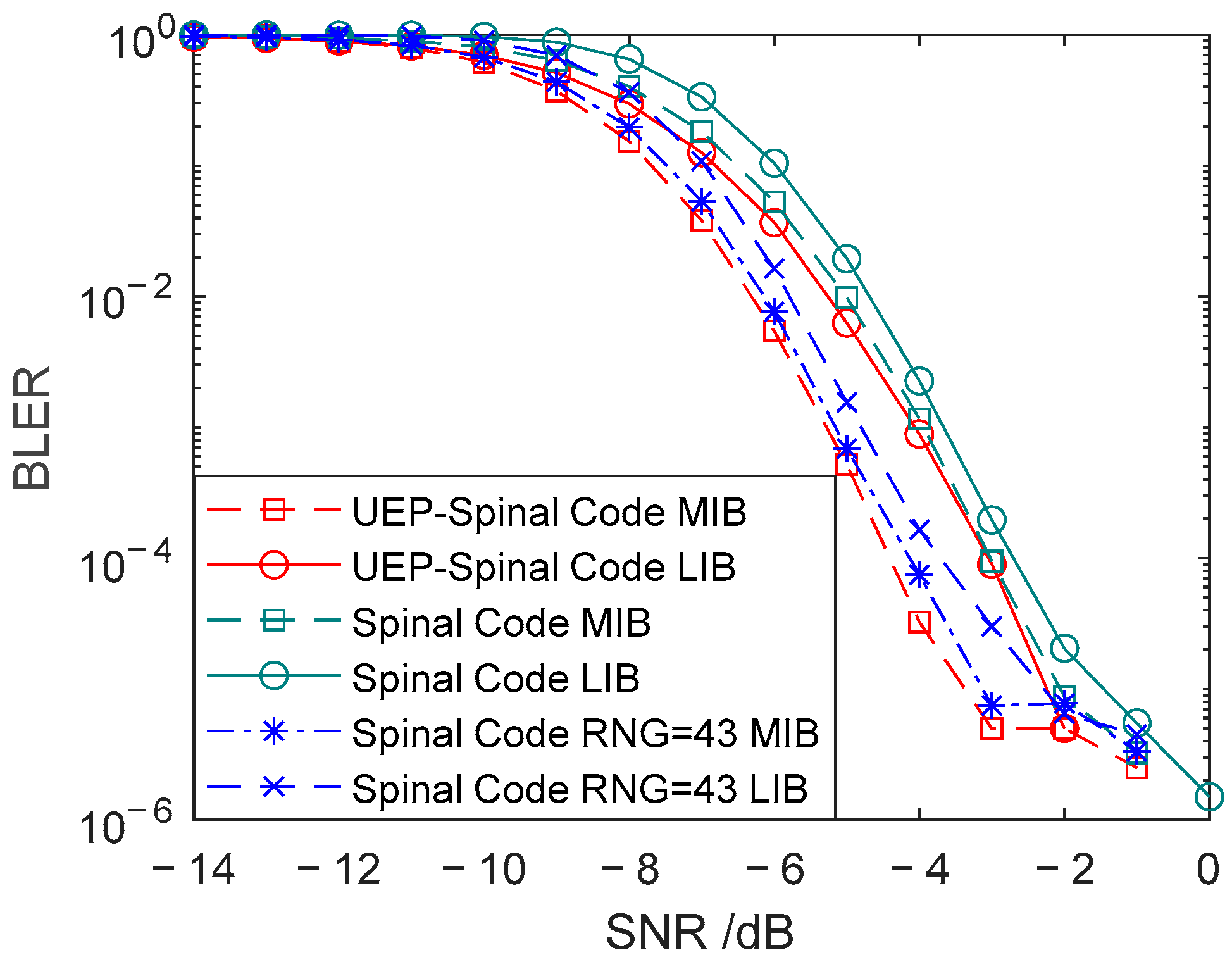
Figure 6 shows the comparison of BLER for Superposition UEP-Spinal Codes, Spinal codes, and Spinal codes mapped to 43-bit encoded packets under AWGN channel conditions with an SNR ranging from −14 dB to 0 dB. Figure 7 presents the comparison of spectral efficiency for the three encoding methods, representing the achievable information rate per unit bandwidth. The duty cycle of the weight factor matrix P in the Superposition UEP-Spinal Codes is set to 1. Figure 6 shows the comparison of BLER for three different encoding algorithms. For each algorithm, the block error rate for both MIBs and LIB is calculated. By comparing the block error rates for these different algorithms in MIBs and LIBs, the communication performance of each encoding scheme is further evaluated, and the effectiveness of the unequal error protection mechanism is validated. Figure 7 displays the bandwidth utilization for different encodings. By comparing the bandwidth utilization, it is confirmed that the Superposition UEP-Spinal encoding algorithm is similar to the previously improved Spinal code mapped to 43-bit encoded packets through RNG in terms of bandwidth efficiency, indicating that the Superposition UEP-Spinal encoding algorithm does not cause any loss in basic performance.
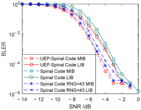
Figure 6.
Comparison of communication performance for head and tail codes of three encoding methods.
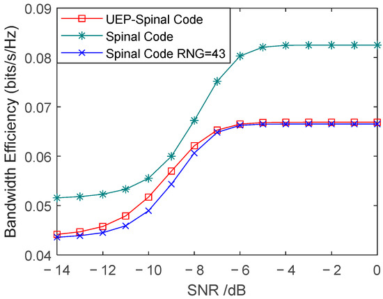
Figure 7.
Comparison of bandwidth efficiency for different encoding methods in AWGN channel.
As shown in Figure 7, due to the increased encoding complexity of the Superposition UEP-Spinal Codes, they sacrifice approximately 25% of the spectral efficiency compared to Spinal codes, while their spectral efficiency is almost the same as that of Spinal codes mapped to 43 bits through RNG. From the communication performance comparison in Figure 6, it is evident that the Superposition UEP-Spinal Codes achieve significant performance improvements over Spinal codes. The Superposition UEP-Spinal Code demonstrates excellent performance in protecting the tail bits, with its tail BLER significantly lower than the head BLER of the Spinal code. Compared to the Spinal code, the Superposition UEP-Spinal Code reduces the average BLER of the tail by , achieving an average reduction of 23.62%, while the head BLER decreases by , with an average reduction of 18.58%. Compared to the RNG-mapped Spinal code, the head BLER of the Superposition UEP-Spinal Code decreases by , achieving an average reduction of 5.04%. However, since the Superposition UEP-Spinal Code prioritizes protecting the head for better communication performance, it sacrifices part of the tail protection, leading to an increase in the average BLER of the tail by within the SNR range of −7 dB to −2 dB, corresponding to an average increase of 34.42%.
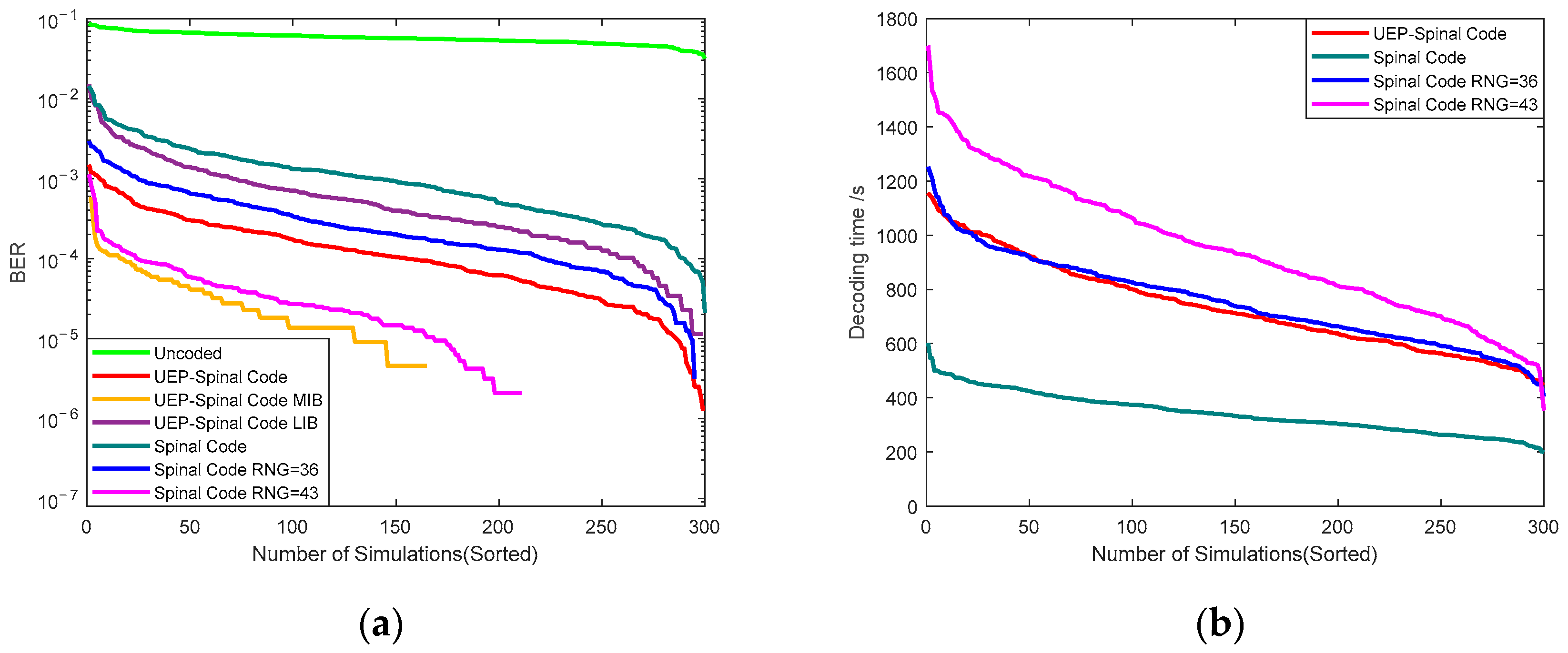
To validate the encoding performance of the Superposition UEP-Spinal Code in underwater high-dynamic channels, simulations are conducted using an additive white Gaussian noise channel (with an SNR dynamic range from −5 dB to 0 dB) and a random erasure channel (with erasure probability ranging from 0.3 to 0.7), constructing a composite transmission environment. In each independent experiment, both the SNR value and erasure probability are randomly generated within the specified range. Performance metrics are then calculated from 300 repeated tests, with a single transmission of 4.8 million bits of original data. The remaining parameters follow the simulation configuration mentioned above. The Superposition UEP-Spinal Code and Spinal code are mapped to 36-bit and 43-bit encoded packets through RNG and transmitted over a simulated random channel. Transmission accuracy and decoding time are recorded to assess the communication performance of different encoding algorithms in highly variable underwater channels. Figure 8a presents the BER curves for four algorithms: the Superposition UEP-Spinal Code, Spinal code, Spinal code mapped to 36-bit encoded packets via RNG, and Spinal code mapped to 43-bit encoded packets via RNG, as well as the transmission without encoding in the underwater highly variable channel. The curves are sorted from largest to smallest, where the Superposition UEP-Spinal Code includes three distinct BER curves: MIBs, LIBs, and overall combined performance. Figure 8b compares the decoding times for the four encoding methods. The decoding time provides an intuitive way to compare the decoding complexity and delay of each encoding scheme. Due to the inherent uncertainty of the communication environment caused by the random channel’s time-varying characteristics, the error rates and decoding delays of each simulation show significant dispersion. To systematically evaluate the encoding algorithm’s performance, Figure 8 ranks the probability distribution curves of all test results from largest to smallest for analysis. From Figure 8, it is evident that the unequal error protection mechanism of the Superposition UEP-Spinal Code provides adequate protection for the MIB, and its decoding complexity is lower compared to the Spinal code with 43-bit encoded packets mapped through RNG.
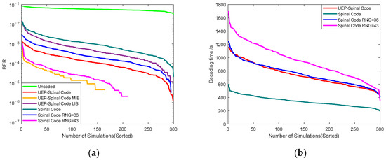
Figure 8.
Comparison of different encoding methods in a simulated random channel. (a) Comparison of BER for different encoding methods. (b) Comparison of decoding time for different encoding methods.
From Figure 8a, it can be observed that the overall BER performance is arranged from lowest to highest as follows: Superposition UEP-Spinal Code MIB, Spinal code mapped to 43-bit encoded packets via RNG, Superposition UEP-Spinal Code, Spinal code mapped to 36-bit encoded packets via RNG, Superposition UEP-Spinal Code LIB, and Spinal code. From Figure 8b, the decoding times are arranged from lowest to highest as follows: Spinal code, Superposition UEP-Spinal Code, Spinal code mapped to 36-bit encoded packets via RNG, and Spinal code mapped to 43-bit encoded packets via RNG. Based on the comprehensive simulation results, it can be concluded that the Superposition UEP-Spinal Code, due to its unequal error protection algorithm, shows superior BER performance for the protected header code compared to the Spinal code mapped to 43-bit encoded packets via RNG, enabling more reliable transmission. At the same time, the decoding time for the Superposition UEP-Spinal Code is lower than that of the Spinal code mapped to 43-bit encoded packets via RNG, thus simplifying the complexity of the communication system. Furthermore, under the unequal error protection algorithm, the tail code structure of the Superposition UEP-Spinal Code is more compact, and it exhibits a lower error rate compared to the Spinal code with the same transmission code length. Given that the Superposition UEP-Spinal Code emphasizes protecting the header code, its overall error rate is lower than that of the Spinal code mapped to 36-bit encoded packets via RNG. In conclusion, benefiting from the unequal error protection algorithm, the Superposition UEP-Spinal Code offers high transmission reliability and low decoding complexity, and it provides a stable, reliable, and timely encoding solution for underwater wireless optical communication.
Through simulation, it can be observed that the Superposition UEP-Spinal Codes are an improved encoding method based on Spinal Codes. Although they increase encoding complexity, they enhance the reliability of the encoding under low SNR conditions. Compared to Spinal codes mapped to 43 bits through RNG, while the overall communication performance is similar, the Superposition UEP-Spinal Codes enhance the communication performance of head codes by sacrificing part of the tail code performance. This makes them highly suitable for use in underwater wireless optical communication, where channel conditions change randomly, as they improve the reliability of transmitting critical data.
6. Conclusions
This paper proposes a novel improved encoding scheme based on Spinal codes, aimed at effectively transmitting information of varying importance and reducing decoding computational overhead. The new Superposition UEP-Spinal Code structure fully leverages the characteristics of unequal error protection, adjusting the encoding method of Spinal codes to assign different encoding priorities based on the importance of the information. Compared to traditional mapping encoding methods, this improvement simplifies the encoding structure and enhances decoding efficiency. The Superposition UEP-Spinal Codes divide the signal into two parts, important information and secondary information, applying different encoding strategies for superposition processing. Compared to Spinal codes, the encoded Superposition UEP-Spinal Code achieves an average BLER reduction of 23.62% for the LIB tail. During the encoding of MIB information, check bits are introduced, increasing the Euclidean distance between nodes and thereby reducing the number of searches. By increasing the Euclidean distance between nodes, the demodulation algorithm’s ability to differentiate between nodes can be effectively improved. As the geometric distance between adjacent nodes in the signal space increases, the isolation of their corresponding decision regions is enhanced, thereby reducing the probability of misjudgment caused by confusion between neighboring nodes. This geometric feature optimization fundamentally reduces the generation of erroneous branches in the decoding tree, preventing redundant searches along incorrect paths and significantly decreasing the number of searches. Compared to the RNG-mapped Spinal code with the same spectral efficiency, the Superposition UEP-Spinal Code achieves an average BLER reduction of 5.04% for MIBs while reducing decoding complexity by 13.3%, saving computational resources. This provides a more stable, reliable, and efficient communication method for underwater wireless optical communication, where channel conditions are relatively random.
Author Contributions
X.Y.: conceptualization, methodology, and writing—original draft; M.Y.: formal analysis and writing—original draft; Y.Z.: writing—review and editing; T.C.: software. All authors have read and agreed to the published version of the manuscript.
Funding
This research was funded by the General Project of the National Natural Science Foundation of China, grant number 52271349.
Institutional Review Board Statement
Not applicable.
Informed Consent Statement
Not applicable.
Data Availability Statement
Some codes generated or used during this study are available from the corresponding author upon request.
Conflicts of Interest
The authors declare no conflicts of interest.
References
- Zhang, H.; Liu, J.; Ye, X.; Bai, Y.; Sun, D.; Wang, S.; Dong, J. Detecting Sargassum bloom directly from satellite top-of-atmosphere reflectance with high-resolution images. IEEE Trans. Geosci. Remote Sens. 2023, 61, 4206212. [Google Scholar] [CrossRef]
- Weng, Y.; Pajarinen, J.; Akrour, R.; Matsuda, T.; Peters, J.; Maki, T. Reinforcement learning based underwater wireless optical communication alignment for autonomous underwater vehicles. IEEE J. Ocean. Eng. 2022, 47, 1231–1245. [Google Scholar] [CrossRef]
- Café, R.; Cabecinhas, D.; Pascoal, A. Hybrid ROV/AUV underwater robotic system for safe and robust remote operations. In Proceedings of the OCEANS 2024-Singapore, Singapore, 14–18 April 2024; pp. 1–6. [Google Scholar]
- Nguyen, N.-T.; Heldal, R.; Lima, K.; Oyetoyan, T.D.; Pelliccione, P.; Kristensen, L.M.; Høydal, K.W.; Reiersgaard, P.A.; Kvinnsland, Y. Engineering challenges of stationary wireless smart ocean observation systems. IEEE Internet Things J. 2023, 10, 14712–14724. [Google Scholar] [CrossRef]
- Tu, J.; Li, J.; Wen, T.; Xiao, Y.; Lu, Q.; Zhao, J.; Chen, Y.; Gao, H.; Shen, L.; Zhang, L. OAM-SDM solution toward a submarine cable. J. Light. Technol. 2022, 41, 1963–1973. [Google Scholar] [CrossRef]
- Sendra, S.; Lloret, J.; Rodrigues, J.J.; Aguiar, J.M. Underwater wireless communications in freshwater at 2.4 GHz. IEEE Commun. Lett. 2013, 17, 1794–1797. [Google Scholar] [CrossRef]
- Chen, W.; Tao, J.; Ma, L.; Qiao, G. Vector-Approximate-Message-Passing-Based Channel Estimation for MIMO-OFDM Underwater Acoustic Communications. IEEE J. Ocean. Eng. 2024, 49, 496–506. [Google Scholar] [CrossRef]
- Duntley, S.Q. Light in the sea. JOSA 1963, 53, 214–233. [Google Scholar] [CrossRef]
- Pompili, D.; Akyildiz, I.F. Overview of networking protocols for underwater wireless communications. IEEE Commun. Mag. 2009, 47, 97–102. [Google Scholar] [CrossRef]
- Partan, J.; Kurose, J.; Levine, B.N. A survey of practical issues in underwater networks. ACM SIGMOBILE Mob. Comput. Commun. Rev. 2007, 11, 23–33. [Google Scholar] [CrossRef]
- Yang, X.; Zhang, Y.; Hua, Y.; Tong, Z.; Wang, R.; Song, G.; Zhang, C.; Liu, S.; Zou, H.; Zhang, H. 50-M/300-Mbps underwater wireless optical communication using incoherent light source. J. Light. Technol. 2023, 41, 6939–6948. [Google Scholar] [CrossRef]
- Kumar, L.B.; Ramavath, P.N.; Krishnan, P. Performance analysis of multi-hop FSO convergent with UWOC system for security and tracking in navy applications. Opt. Quantum Electron. 2022, 54, 327. [Google Scholar] [CrossRef]
- Chaudhary, S. Performance investigation of a VLC-PDM based UWOC system under adverse underwater conditions with varying chlorophyll levels. Opt. Commun. 2024, 573, 131025. [Google Scholar] [CrossRef]
- Zhang, D.; N’Doye, I.; Ballal, T.; Al-Naffouri, T.Y.; Alouini, M.-S.; Laleg-Kirati, T.-M. Localization and tracking control using hybrid acoustic–optical communication for autonomous underwater vehicles. IEEE Internet Things J. 2020, 7, 10048–10060. [Google Scholar] [CrossRef]
- Yadav, S.; Vats, A.; Aggarwal, M.; Ahuja, S. Performance analysis and altitude optimization of UAV-enabled dual-hop mixed RF-UWOC system. IEEE Trans. Veh. Technol. 2021, 70, 12651–12661. [Google Scholar] [CrossRef]
- Perry, J.; Balakrishnan, H.; Shah, D. Rateless spinal codes. In Proceedings of the 10th ACM Workshop on Hot Topics in Networks, New York, NY, USA, 14–15 November 2011; pp. 1–6. [Google Scholar]
- Ogata, S.; Ishibashi, K. On dynamic cooperative diversity based on dual-spinal codes. IEICE Tech. Rep. 2014, 113, 181–186. [Google Scholar]
- El-Khamy, S.E.; ElFar, S.H.; Rizk, M.R. A novel secure signaling technique for underwater communication channels based on differential frequency hopping and spinal codes. In Proceedings of the 2017 International Conference on Computational Science and Computational Intelligence (CSCI), Las Vegas, NV, USA, 14–16 December 2017; pp. 599–604. [Google Scholar]
- Wang, L.; Chen, X.; Tan, H. Research and Implementation of Rateless Spinal Codes Based Massive MIMO System. Wirel. Commun. Mob. Comput. 2018, 2018, 6101853. [Google Scholar] [CrossRef]
- Li, A.; Wu, S.; Jiao, J.; Zhang, N.; Zhang, Q. Spinal codes over fading channel: Error probability analysis and encoding structure improvement. IEEE Trans. Wirel. Commun. 2021, 20, 8288–8300. [Google Scholar] [CrossRef]
- Perry, J.; Iannucci, P.A.; Fleming, K.E.; Balakrishnan, H.; Shah, D. Spinal codes. ACM SIGCOMM Comput. Commun. Rev. 2012, 42, 49–60. [Google Scholar] [CrossRef]

Disclaimer/Publisher’s Note: The statements, opinions and data contained in all publications are solely those of the individual author(s) and contributor(s) and not of MDPI and/or the editor(s). MDPI and/or the editor(s) disclaim responsibility for any injury to people or property resulting from any ideas, methods, instructions or products referred to in the content. |
© 2025 by the authors. Licensee MDPI, Basel, Switzerland. This article is an open access article distributed under the terms and conditions of the Creative Commons Attribution (CC BY) license (https://creativecommons.org/licenses/by/4.0/).