Article

A High-Resolution Mirror Migration Framework for Ocean Bottom Cable Seismic Data

1
Hubei Subsurface Multi-Scale Imaging Key Laboratory, School of Geophysics and Geomatics, China University of Geosciences, Wuhan 430074, China
2
Innovation Academy for Precision Measurement Science and Technology, Chinese Academy of Sciences, Wuhan 430077, China
3
R&D Center, Sinopec Geophysical Corporation, Nanjing 211106, China
*
Author to whom correspondence should be addressed.
J. Mar. Sci. Eng. 2025, 13(12), 2254; https://doi.org/10.3390/jmse13122254
Submission received: 12 October 2025 / Revised: 24 November 2025 / Accepted: 25 November 2025 / Published: 27 November 2025
(This article belongs to the Special Issue Modeling and Waveform Inversion of Marine Seismic Data)

Abstract

Seismic data migration is a critical step for accurate subsurface imaging. While Ocean Bottom Cable (OBC) surveys provide high-quality seismic data, reliance on primary reflections alone leads to significant illumination gaps. Receiver-side ghost waves can mitigate these gaps; however, conventional mirror migration suffers from low resolution and amplitude inaccuracy. To address these limitations, this study introduces a high-resolution mirror migration framework based on Point Spread Function (PSF)-guided inversion imaging. The methodology involves first separating the OBC wavefield to isolate ghost-wave components, followed by applying standard mirror migration to produce an initial, blurred image. Subsequently, the PSFs of down-going ghost waves are estimated to characterize imaging distortions, and image-domain least squares migration (LSM) is implemented via PSF deconvolution to reconstruct high-resolution reflectivity. Numerical experiments on complex models demonstrate that the proposed method preserves the additional illumination provided by this wavefield, substantially improves the spatial resolution of imaging targets, and enhances lateral continuity. Quantitative analysis confirms this enhancement through a significant extension of the effective vertical wavenumber bandwidth and the recovery of higher-frequency content. The framework provides a robust and computationally efficient solution for high-fidelity OBC imaging, enabling more reliable subsurface interpretation.

1. Introduction

Ocean Bottom Cable (OBC) seismic acquisition has become a key technology for exploration in offshore oil and gas development [1,2]. By deploying receivers on the seafloor, OBC acquisition improves the signal-to-noise ratio (S/N) and provides broader subsurface coverage compared with conventional towed-streamer surveys [3]. Due to these advantages, OBC data has been widely applied not only for static structural imaging but also for dynamic seismic surveillance and reservoir monitoring. For instance, high-resolution imaging of Bottom-Simulating Reflectors (BSRs) is essential for characterizing gas hydrate systems [4]. Furthermore, the strategies of Ocean Bottom Node (OBN) and OBC processing are evolving to support time-lapse (4D) monitoring, where the repeatability of imaging artifacts caused by multiples must be strictly controlled [5].
Despite these advancements, a fundamental limitation remains: traditional OBC imaging based solely on primary reflections often fails to adequately illuminate complex geological structures. Constrained by limited receiver spacing and single-sided illumination geometry, primary reflections leave significant illumination gaps, a challenge that is particularly pronounced beneath high-velocity layers or steeply dipping formations [6].
To address illumination deficiencies, researchers have increasingly turned to multiple reflections—specifically, receiver-side ghost waves. These downgoing reflections from the sea surface follow different propagation paths than primaries, effectively illuminating the “shadow zones” of primary imaging. Mirror migration provides such a strategy by treating the sea surface as a virtual mirror, enabling these ghost reflections to be processed as if they were primary waves from mirrored receiver locations [7]. This approach has proven effective in improving the imaging of shallow and steeply dipping structures [8,9] and has been successfully integrated with advanced algorithms such as reverse-time migration (RTM) across different acquisition systems [10,11,12].
However, the success of this strategy fundamentally depends on the quality of the input data. Migrating the full wavefield introduces severe crosstalk; thus, high-fidelity wavefield separation is a prerequisite [13,14]. While recent deep learning advancements have demonstrated efficacy in attenuating multiples [15,16], their performance relies heavily on the availability and representativeness of training datasets, which are often scarce in practical scenarios. Consequently, a rigorous, physics-based wavefield separation method using the representation theorem remains a necessary and robust alternative to ensure accurate wavefield isolation.
Even with high-fidelity separation, conventional mirror migration still suffers from inherent limitations in resolution and amplitude fidelity. As a standard adjoint operator, it lacks the inverse Hessian correction, resulting in amplitude imbalances and a loss of high-wavenumber content that restricts detailed stratigraphic interpretation [9,17,18]. Moreover, state-of-the-art methods like elastic Full-Waveform Inversion (FWI) are pushing imaging from kinematics to dynamics. Although FWI provides superior model parameter updates, its high computational cost often limits its routine application for high-resolution structural imaging compared to efficient migration-based approaches [19].
To bridge this gap, this paper introduces a high-resolution mirror migration framework that integrates conventional mirror migration with Point Spread Function (PSF)-guided deconvolution. The method explicitly models the imaging distortions introduced by the mirror-migration operator using a PSF and subsequently corrects these distortions through inverse filtering in the image domain. By incorporating the physical characteristics of the ghost wavefield into the inversion process, this approach achieves high-resolution imaging with modest computational cost. A series of numerical experiments on representative geological models demonstrate the effectiveness of the proposed framework.

2. Methodology

2.1. Principles of Mirror Migration

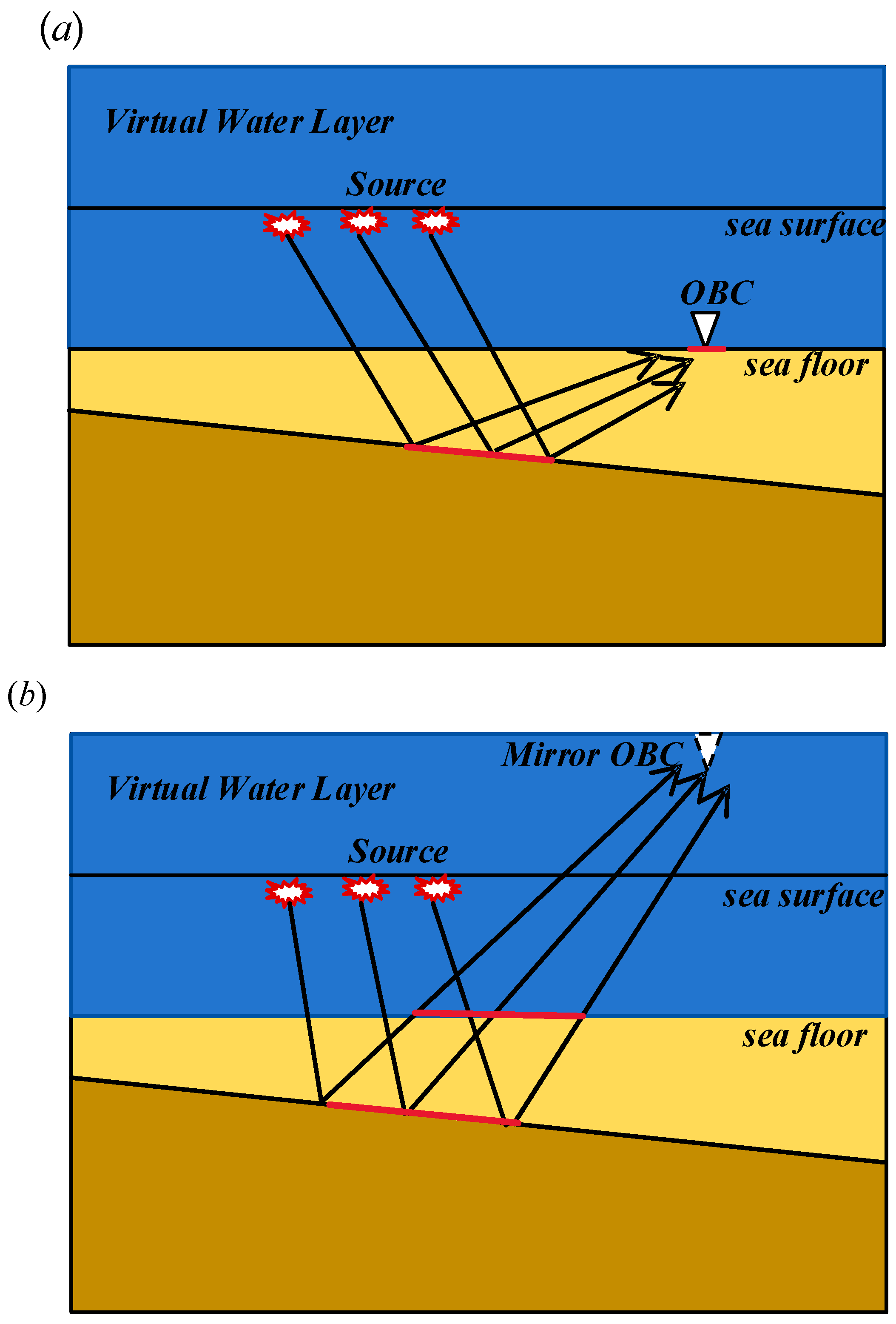
Mirror migration utilizes receiver-side ghost waves to enhance subsurface illumination in OBC seismic data. The technique constructs a virtual mirror of the acquisition geometry by conceptually extending the water column above the sea surface and mirroring the seabed receiver positions within it. This geometric transformation establishes a kinematic equivalence, allowing ghost waves to be treated as primary waves recorded at the mirrored receiver positions. Figure 1 illustrates the distinct wavefield propagation paths for upgoing primary waves and downgoing ghosts in a typical OBC survey.
This approach is motivated by the complementary illumination provided by the primary and receiver-side ghost wavefields, as shown in Figure 2. The illumination from primary waves is typically confined to regions directly beneath the receivers, resulting in imaging gaps in shallow strata. In contrast, receiver-side ghost waves reflected from the sea surface possess broader propagation angles, providing extended lateral coverage that complements the primary illumination zone. Thus, mirror imaging can effectively fill illumination gaps left by primary reflections, particularly improving the imaging of shallow and steeply dipping structures. In this study, we focus primarily on first-order receiver-side ghost waves and ignore higher-order multiples.

2.2. Wavefield Separation on Ocean Bottom Cable Seismic Data

To enable targeted imaging of receiver-side ghost waves, the first step in our workflow is to isolate the ghost-wave field from the full OBC dataset. Traditional separation approaches often suffer from inherent limitations. For instance, filtering methods based on the Radon transform [20] or predictive deconvolution [21] may damage the amplitudes of effective signals or leave residual multiples due to the limited moveout difference in complex geological settings. Similarly, methods based on one-way wave equation propagators [22,23] often introduce kinematic errors at wide propagation angles and fail to accurately handle the vector characteristics of elastic waves [24].
This study adopts a high-fidelity wavefield separation method based on the representation theorem and sequential full-wave finite-difference (FD) propagators [17,25,26]. This rigorous formulation explicitly enforces the free-surface boundary condition and fluid-solid interface conditions without angular limitation. It ensures the accurate preservation of amplitude and phase characteristics for the separated receiver-side ghost wavefield ( D g ) even in the presence of strong lateral velocity variations.
For a closed volume V without internal sources, the wavefield at any internal location can be reconstructed using boundary values on its enclosing surface:
u ( x ) = V [ u ( y ) n G ( x , y ) u ( y ) G ( x , y ) n ] d S ( y )
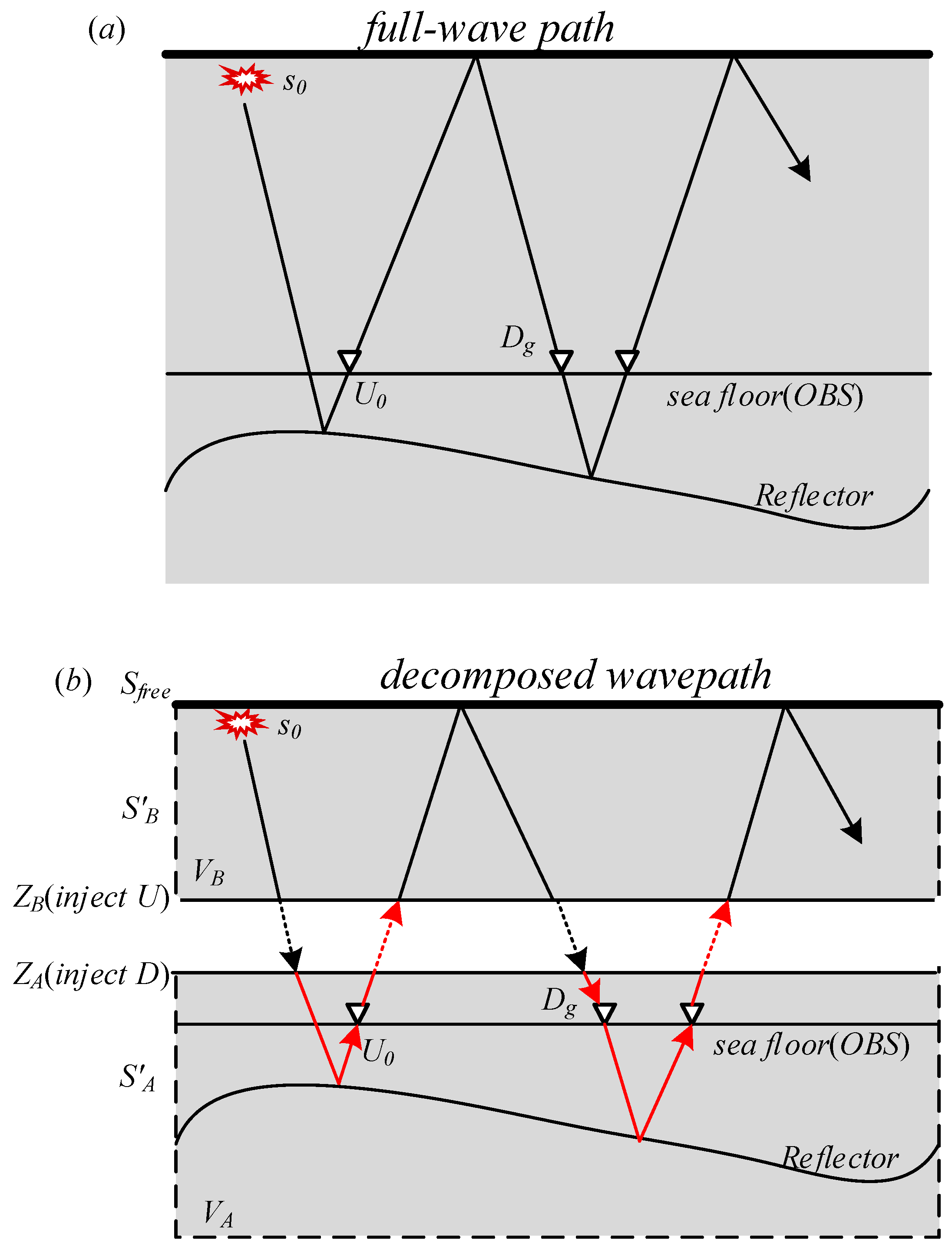
where x is a point within volume V , G is the Green’s function, and u and its normal derivative u n are given on the enclosing surface. By establishing virtual computational boundaries within the model and using this theorem for wavefield injection, specific wavefield components with distinct propagation paths can be effectively tracked and separated [17], as theoretically demonstrated in the decomposition strategy illustrated in Figure 3.
Figure 3 illustrates the decomposition of the wave path. Figure 3a shows the full-wave propagation in the global domain, where the down-going source signal is s 0 . Based on this theorem, the method decomposes the global computational domain into two coupled subdomains using two transparent virtual surfaces, Z A and Z B , located within the water layer (as shown in Figure 3b).
Subsurface Domain V A : Enclosed by the virtual boundary Z A (located just above the seafloor) and an auxiliary outer boundary S A .
Water Layer Domain  V B : Enclosed by the virtual boundary Z B , the free surface S f r e e , and an auxiliary outer boundary S B .
Following the theoretical framework established in previous literature [17,26], we assume that the wavefields on these auxiliary outer boundaries S A and S B satisfy the Sommerfeld radiation condition. This implies that these boundaries are located sufficiently far from the scattering sources or are perfectly absorbing, ensuring that only outgoing waves exist and no energy is reflected back into the computational volume. Consequently, the surface integral contributions over S A and S B vanish in Equation (1). The wavefield reconstruction therefore depends solely on the boundary values recorded on the injection surfaces Z A and Z B and the reflection at S f r e e . The separation workflow implements a sequential injection strategy, as illustrated in Figure 3b:
Incident Wave Simulation ( D 0 ): The source s 0 is excited in the water layer ( V B ). The wavefield propagates downwards to the virtual boundary Z A . The process extracts the wavefield at Z A as the down-going incident source D 0 .
Primary Wave Simulation ( U 0 ): This step injects D 0 into the subsurface domain ( V A ) at boundary Z A (downward injection). The wavefield interacts with the subsurface reflectors and travels upwards to the seafloor. This interaction generates the up-going primary reflection ( U 0 ), which is recorded by the OBS receivers on the seafloor.
Receiver-side Ghost Simulation ( D g ): To simulate the ghost wave, the workflow uses the recorded up-going primary U 0 as a new secondary source. The method injects U 0 back into the water layer domain ( V B ) at boundary Z B (upward injection). The wave propagates to the free surface ( S f r e e ), undergoes reflection (with a reflection coefficient of −1), and travels downwards. This reflected wave passes through Z B and is injected at Z A to finally reach the seafloor, where it is recorded as the down-going receiver-side ghost wave ( D g ).
While this process successfully isolates the desired wavefields, each is subject to different imaging artifacts. Therefore, a subsequent inverse imaging framework is necessary to correct these distortions and achieve optimal resolution.

2.3. PSF of Receiver-Side Ghost Waves and PSF-Based High Resolution Imaging

The imaging process can be described as a linear inverse problem. Under the Born approximation, forward modeling for the separated receiver-side ghost-wave field can be written as:
D g = L g m
where D g represents the observed receiver-side ghost waves data, L g is the Born forward operator specific to the ghost wave propagation paths, and m denotes the subsurface reflectivity. Under the constant-density acoustic assumption, this operator can be represented in the following integral form:
D g ( x r , x s ; ω ) = ω 2 V G ( x r , x ; ω ) m ( x ) G ( x , x s ; ω ) f ( ω ) d V ( x )
where x s and x r represent the coordinates of the source and receiver, respectively; x is the coordinate of a subsurface scatter; ω is the frequency; G is the Green’s function in the background medium; and f ( ω ) is the source wavelet. To simplify computations, this study adopts an asymptotic WKBJ form of the Green’s function [27]. This approximation explicitly separates the wavefield into an amplitude term and a phase term determined by travel time:
G ( ω , x ; x s ) = A ( x ; x s ) e i ω T ( x ; x s )
where T ( x ;   x s ) is the traveltime and A ( x ;   x s ) is the amplitude term, respectively.
Conventional mirror migration generates an initial but blurred subsurface image I g :
I g = L g T D g m = ( L g T L g ) m
Here, H g = L g T L g denotes the Hessian operator, which characterizes the entire imaging system from the true model to the conventional migrated image. The integral kernel of the Hessian operator, H g ( x , x ) can be expressed as:
H g ( x , x ) = d ω d x s d x r ω 2 | f ( ω ) | 2 G * ( x r , x ) G ( x r , x ) G * ( x , x s ) G ( x , x s )
The response of this imaging system to a single point scatterer in the subsurface defines the PSF of the ghosts, denoted P .
Ideally, the true reflectivity could be recovered by inverting the Hessian: m = H g 1 I g . However, explicit computation and inversion of the Hessian are computationally prohibitive for large-scale seismic problems. To overcome this, the method approximates the action of H g locally as a convolution with a spatially varying PSF, where the convolution kernel is the ghost-wave PSF ( P g ). This leads to a convolutional model:
m P g 1 I g
This relation represents a linearized inverse problem in the image domain, aiming to recover the true reflectivity m by removing the blurring effects of the Hessian operator. The objective function is formulated as follows:
J ( m ) = m i n ( | | P g m I g | | 2 2 )
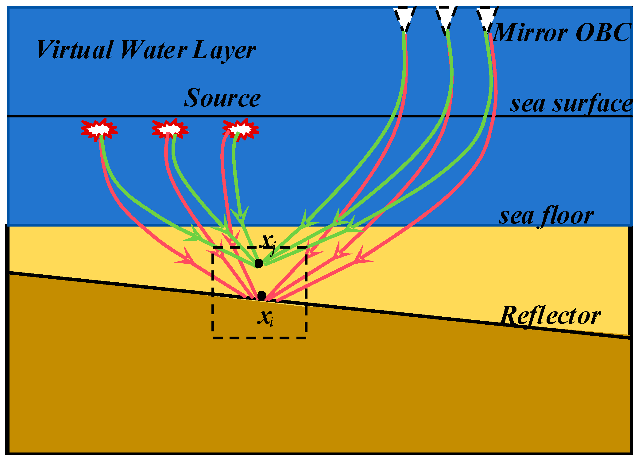
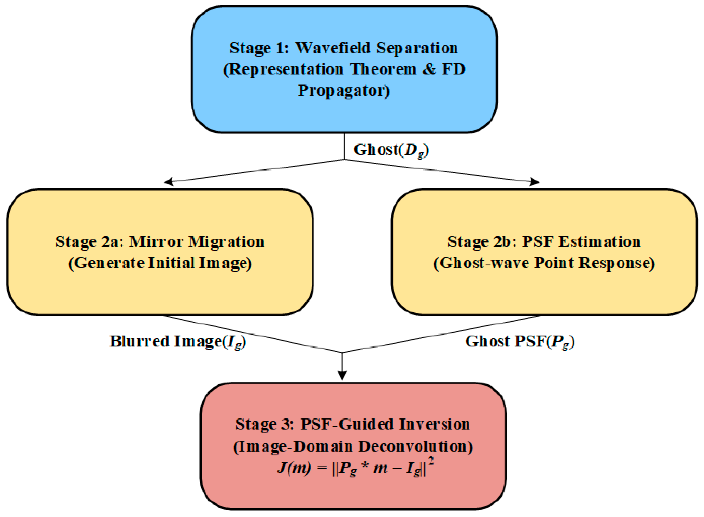
This optimization seeks to find an image m that, when convolved with the ghost-wave PSF, best matches the initial mirror migration image I g in a least-squares sense. The strategy for calculating the PSF is illustrated in Figure 4. The overall workflow of the proposed high-resolution mirror migration method is summarized in Figure 5. It explicitly links the three key stages: (1) wavefield separation to isolate ghost waves, (2) parallel execution of mirror migration and PSF estimation, and (3) the final PSF-guided deconvolution to reconstruct high-fidelity reflectivity.

3. Numerical Examples

3.1. Uplift–Depression Model Test

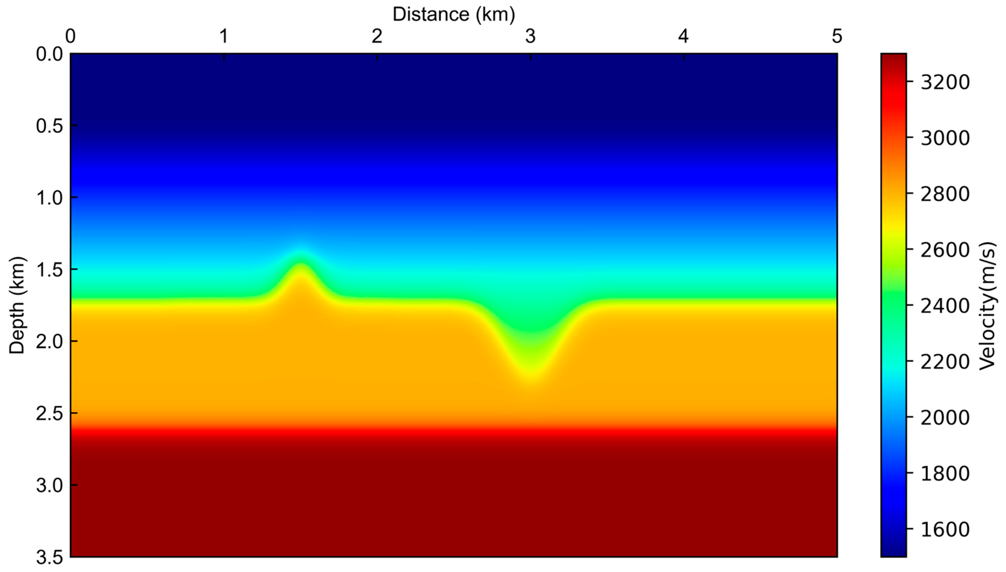
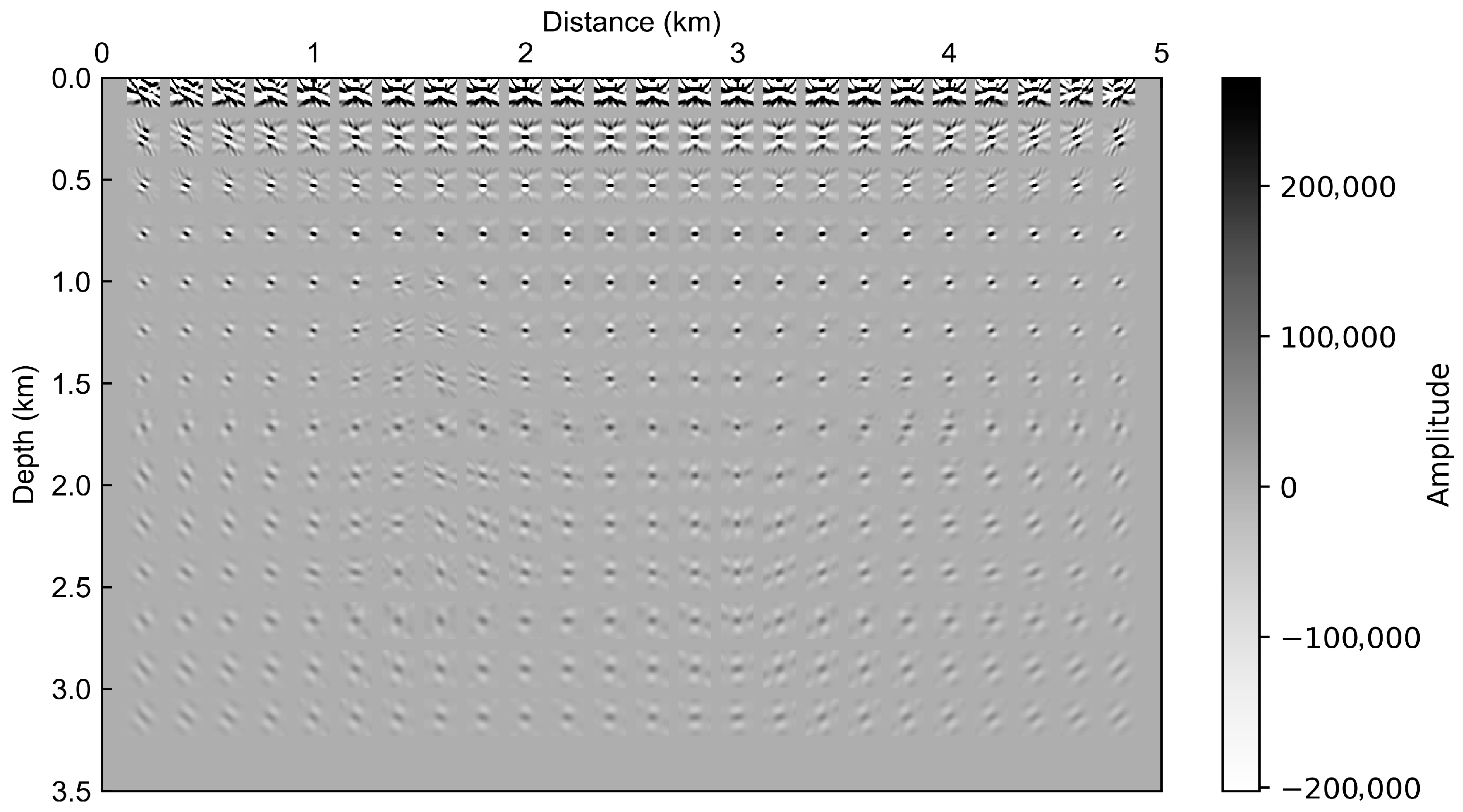
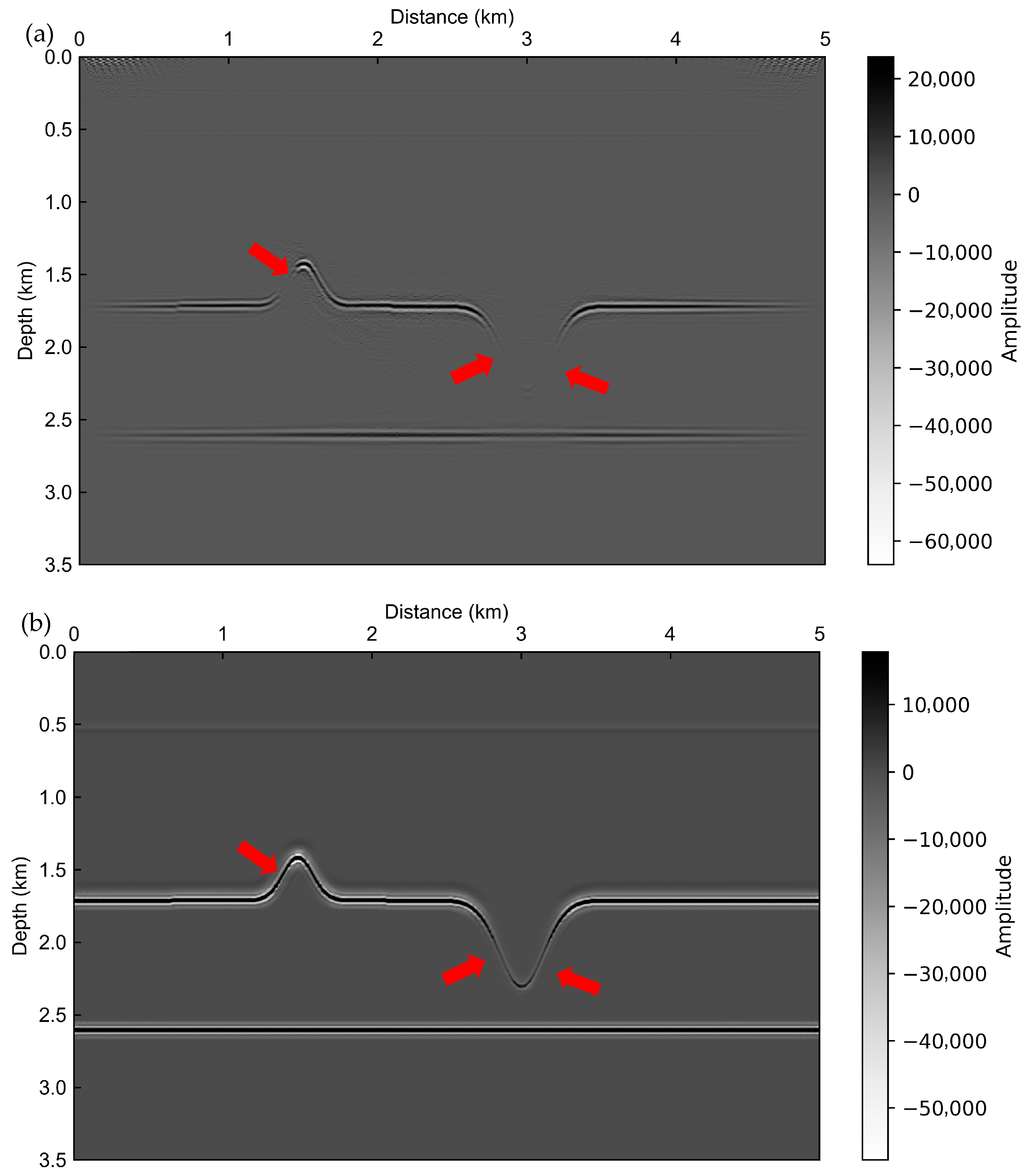
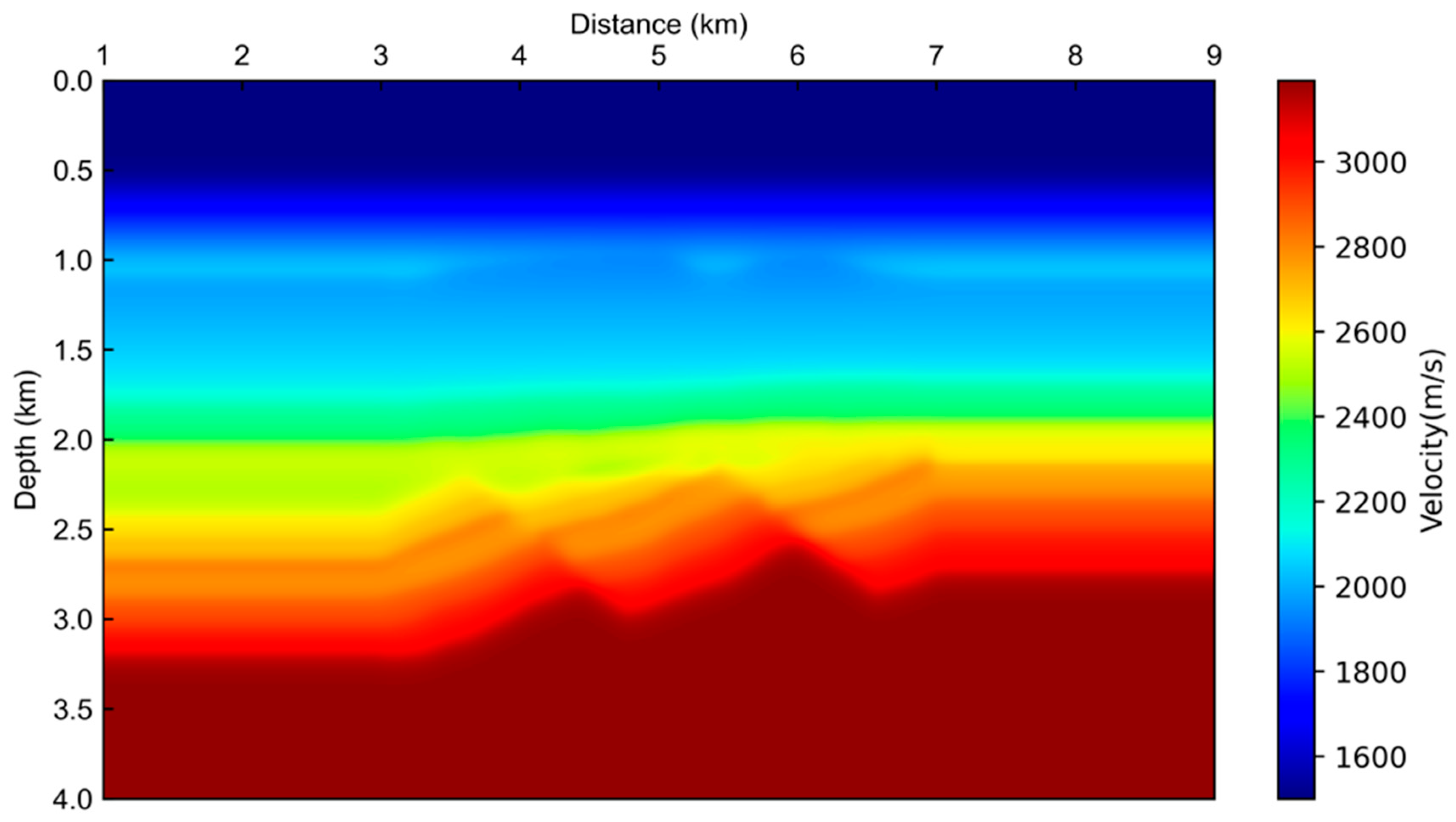
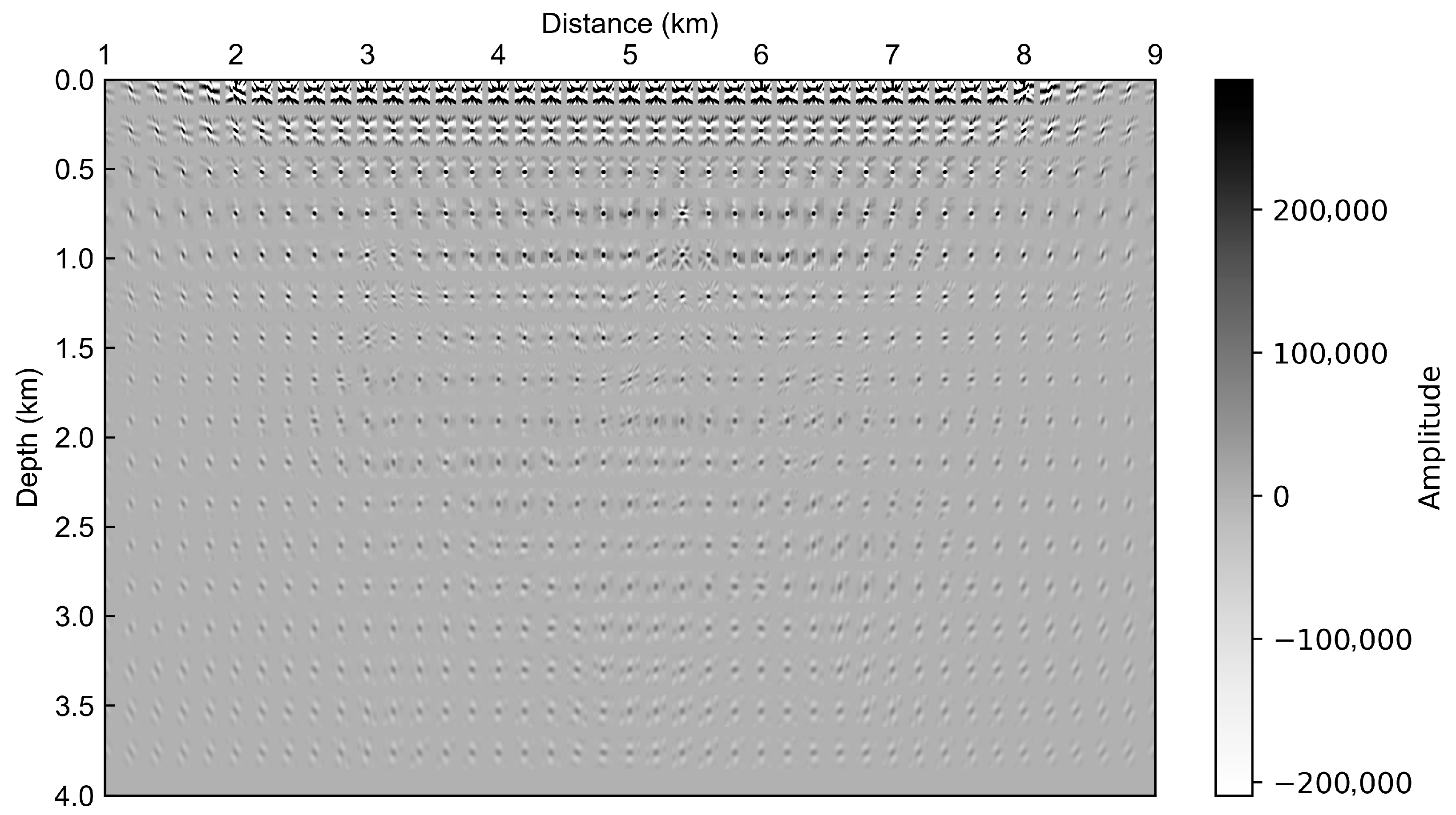
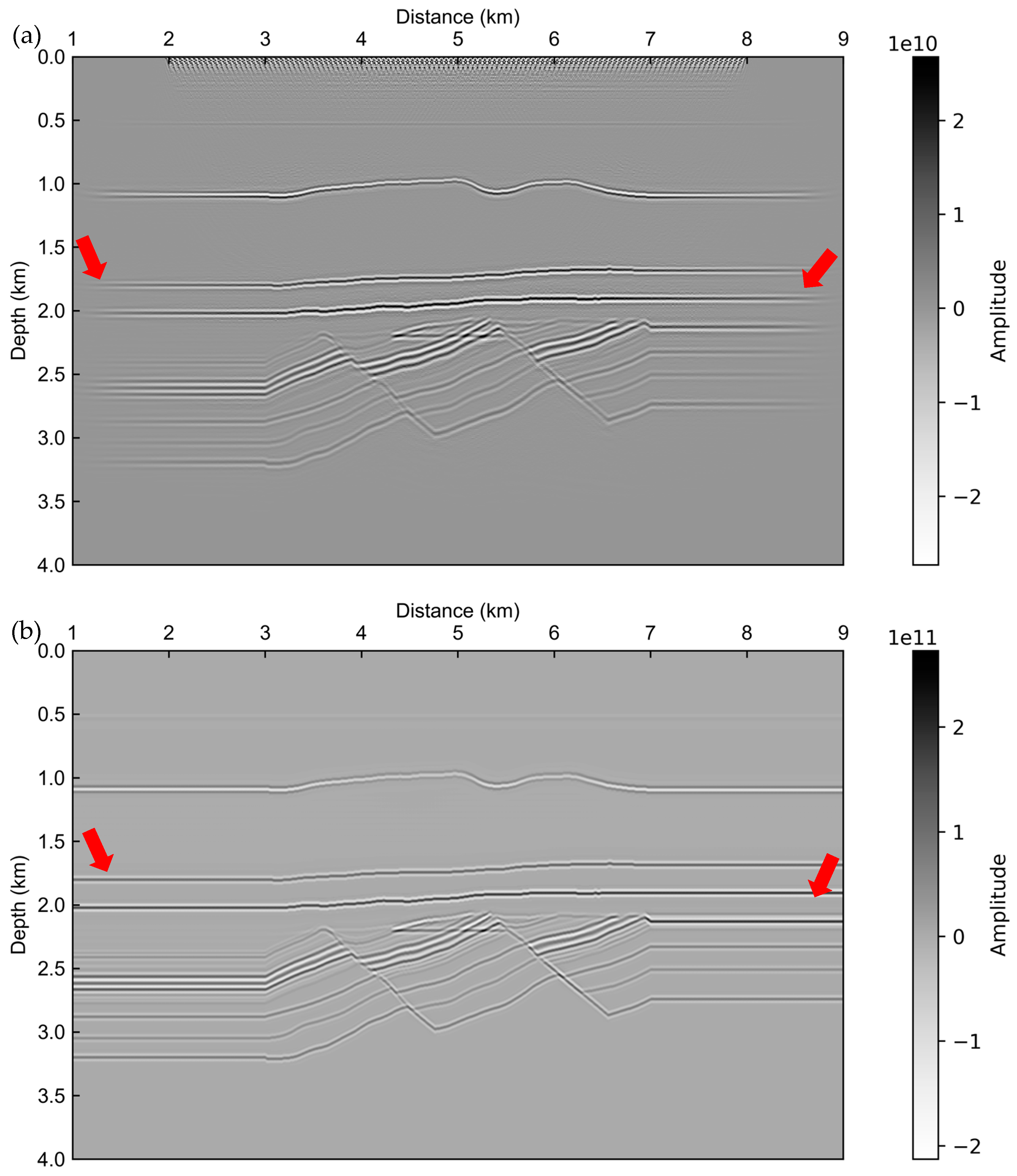
To initially verify the effectiveness of the proposed high-resolution imaging framework, this section employed a synthetic model containing a distinct uplift–depression structure. The model consists of a single uplifted block adjacent to a local depression, designed to test the proposed method’s imaging accuracy in non-horizontal geological settings. The migration velocity model is shown in Figure 6. The corresponding PSF calculated for the receiver-side ghost wavefield is displayed in Figure 7. A comparison of the imaging results in Figure 8 demonstrates that the proposed high-resolution mirror migration method (Figure 8b) enhances reflector clarity and continuity while suppressing the migration artifacts present in the conventional mirror-migration result (Figure 8a).
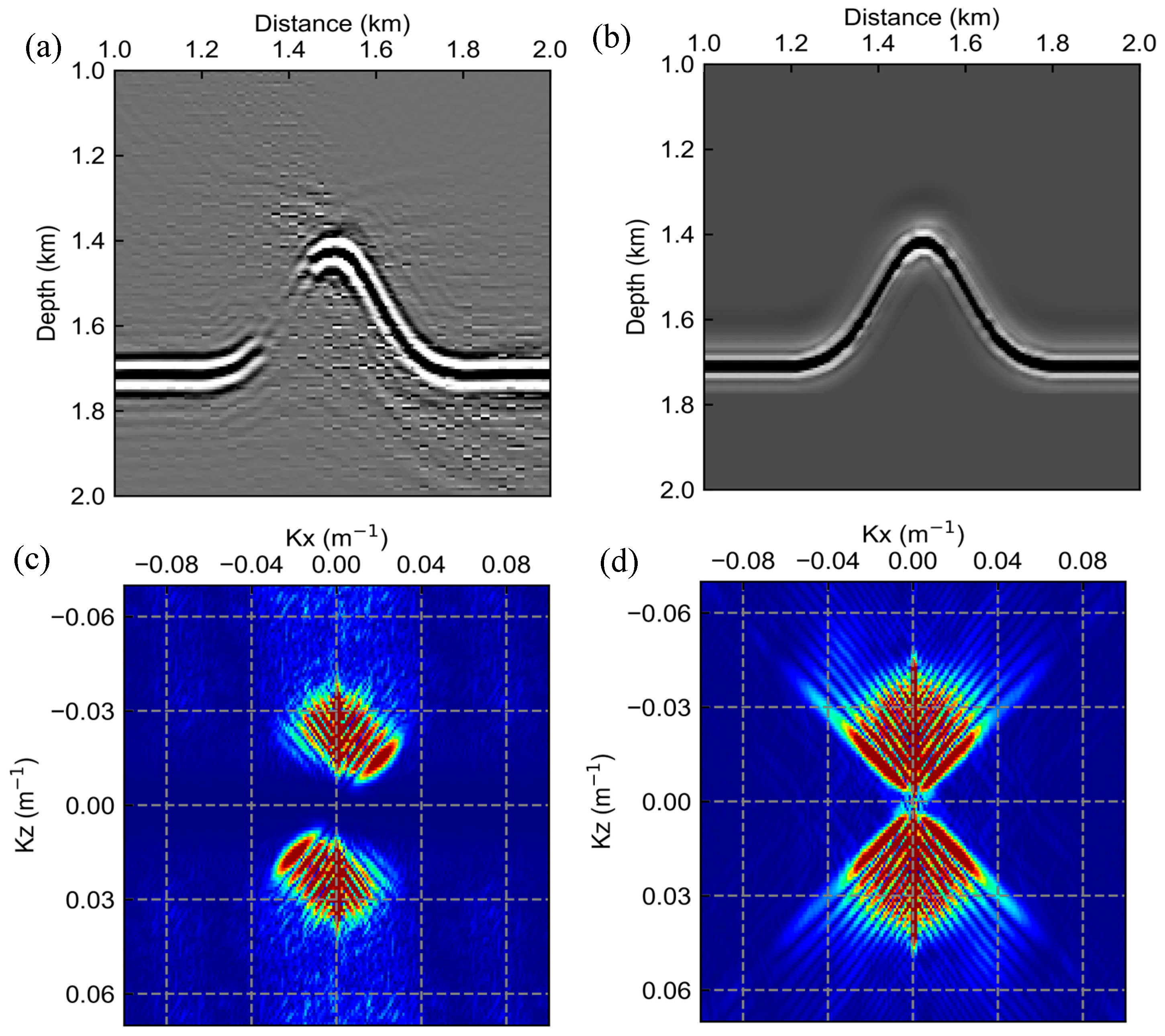
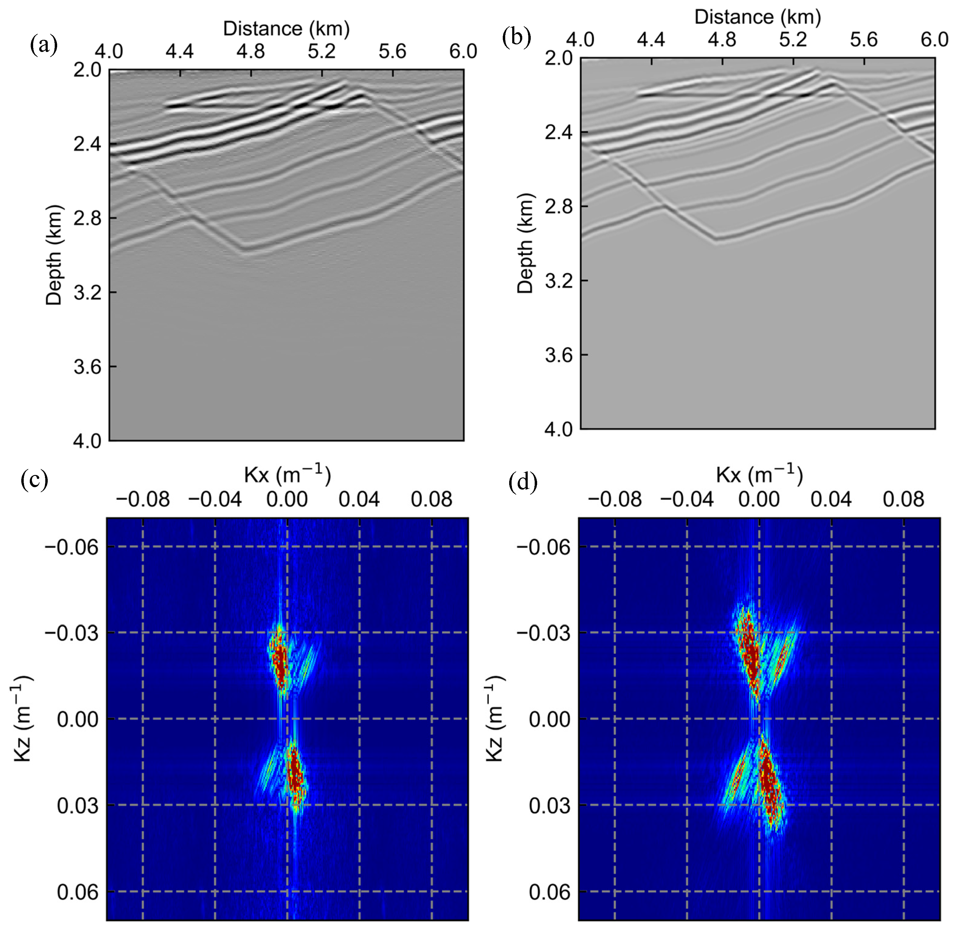
To further illustrate the improvement, a zoomed-in region is displayed in Figure 9. The high-resolution result (Figure 9b) reveals a focused uplift–depression event compared to the blurred output of the conventional method (Figure 9a). The corresponding wavenumber spectra also confirm this enhancement: the spectrum of the proposed method (Figure 9d) exhibits a broader and higher-frequency content than that of the conventional method (Figure 9c), indicating superior resolution and improved recovery of fine structural details.

3.2. Gullfaks Model Test

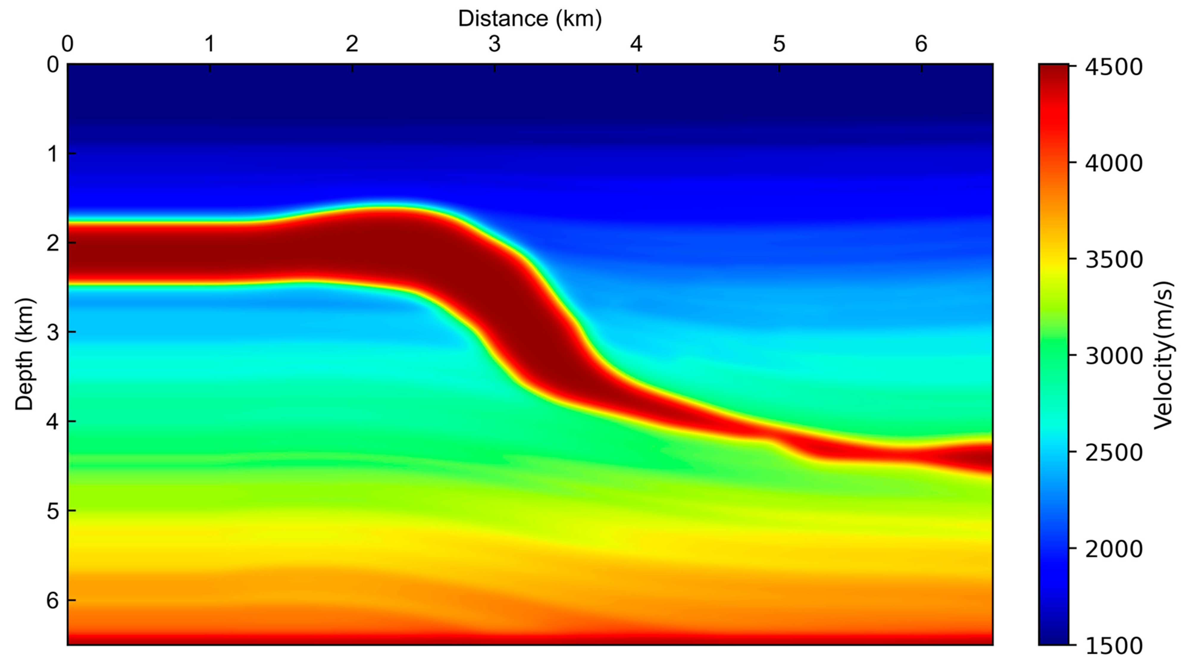
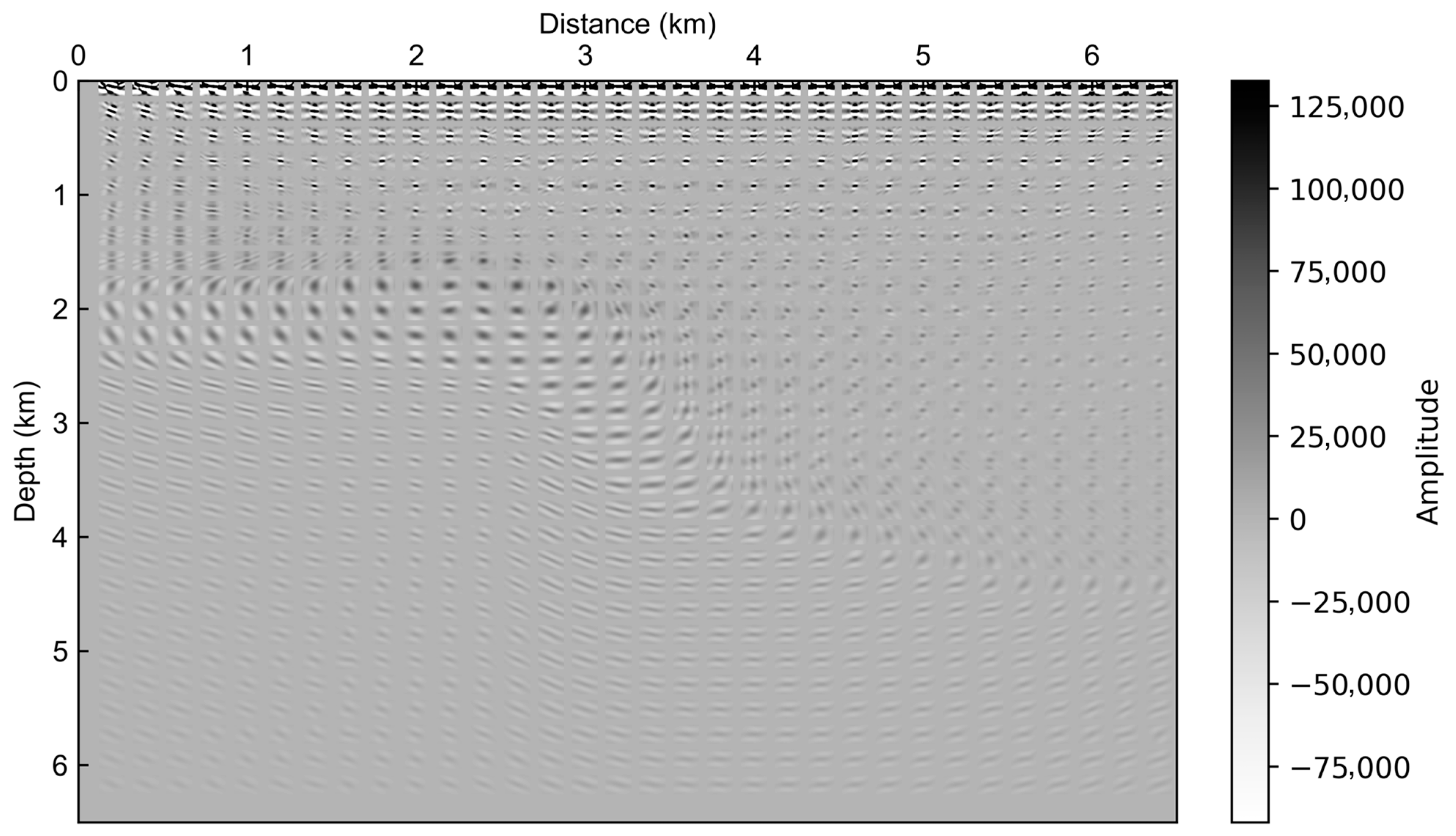
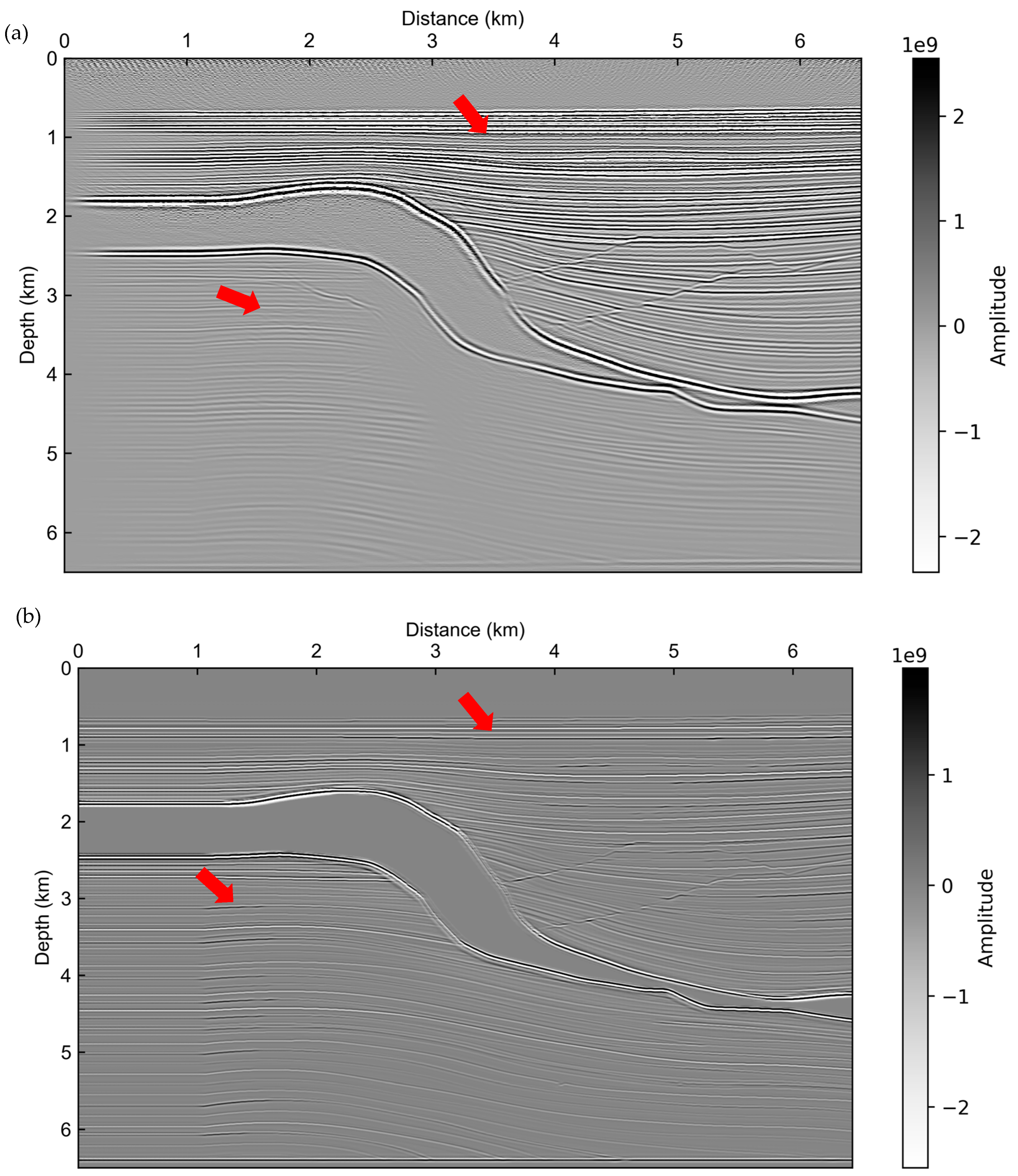
To further evaluate the robustness of the proposed workflow, the Gullfaks model served as a benchmark representing North Sea geology characterized by numerous fault blocks and dipping layers. These structural complexities make the Gullfaks model an ideal benchmark for validating advanced imaging algorithms. The migration velocity model used for this test is shown in Figure 10. The corresponding PSF calculated for the ghost wavefield is displayed in Figure 11. As shown in Figure 12, the proposed high-resolution framework (Figure 12b) produces an image with improved structural clarity and focus compared to the traditional mirror migration result (Figure 12a), which exhibits noticeable migration swing artifacts and reduced resolution.
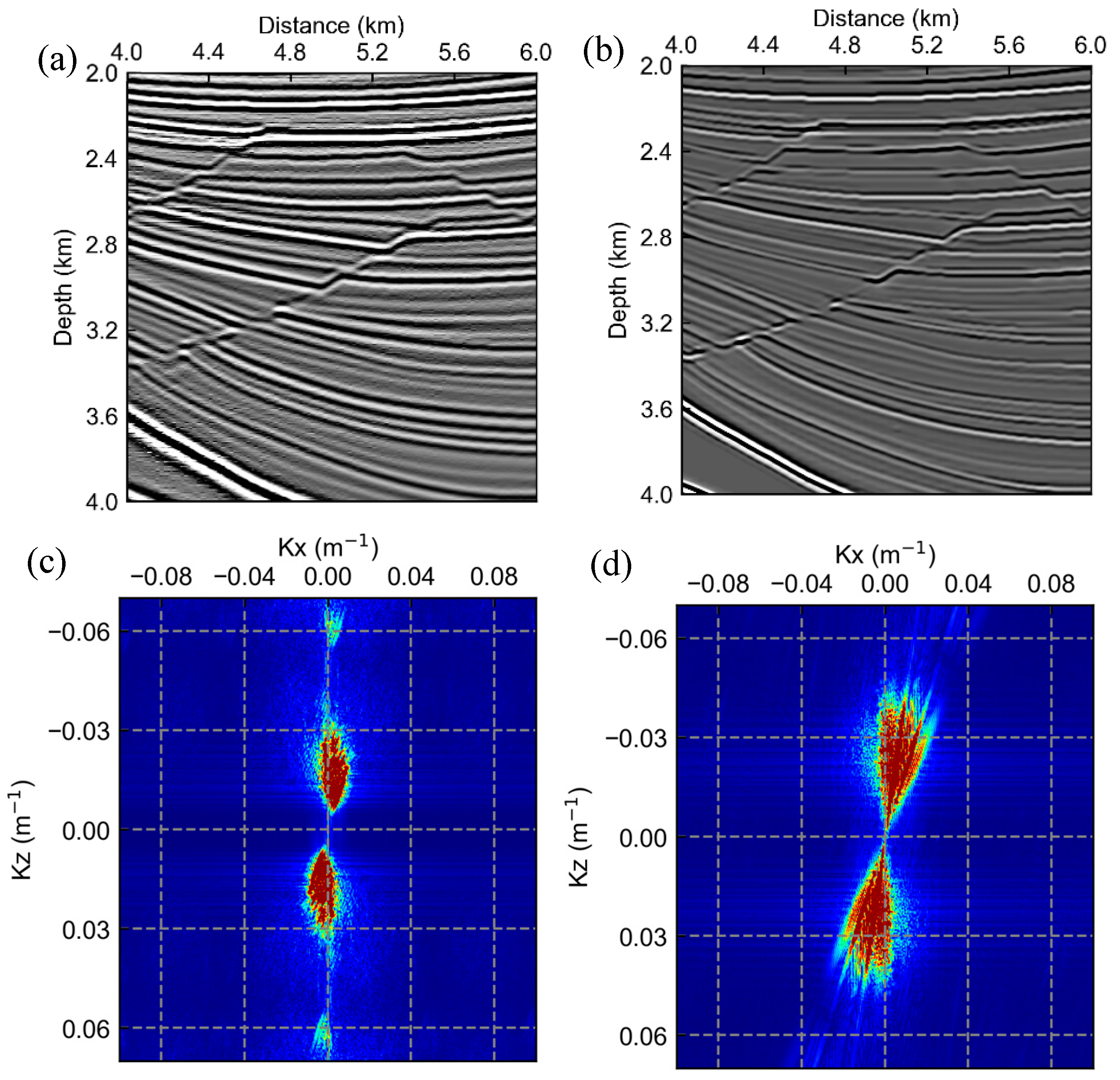
A detailed zoomed-in comparison is presented in Figure 13, where complex faulting and steeply dipping strata are better defined in the high-resolution image (Figure 13b) than in the conventional image (Figure 13a). The wavenumber spectra further confirm this observation: the spectrum from our method (Figure 13d) displays broader and more balanced energy across the wavenumber domain than the conventional one (Figure 13c), evidencing higher fidelity and improved representation of true subsurface reflectivity.

3.3. Pluto Model Test

To assess the performance of the proposed method under geologically challenging conditions, this study employed the Pluto model, which contains large salt bodies with steep flanks that strongly distort seismic wavefields. This model is well known for the difficulty it presents in imaging sub-salt structures. The migration velocity model used for this test is shown in Figure 14. The corresponding PSF calculated for the ghost wavefield is displayed in Figure 15. As presented in Figure 16, the high-resolution mirror migration (Figure 16b) effectively suppresses strong migration artifacts generated by the salt bodies and yields a resolved image of sub-salt reflectors compared to the conventional result (Figure 16a), where the target structures are largely obscured by noise.
Figure 17 further illustrates the superiority of the proposed method. In the zoomed-in comparison, weak and discontinuous sub-salt reflectors are distinguishable with excellent lateral continuity in our result (Figure 17b), whereas they are nearly invisible in the conventional image (Figure 17a). The corresponding wavenumber spectrum of our result (Figure 17d) is significantly extended, especially along the vertical wavenumber axis, compared to the spectrum of the conventional method (Figure 17c). This confirms that our framework effectively recovers high-frequency information, leading to a substantial improvement in resolution and imaging quality in complex sub-salt environments.

4. Discussion

The proposed high-resolution mirror migration method differs from conventional mirror migration mainly in its image-domain compensation strategy. Traditional mirror migration directly maps the ghosts into the subsurface image without compensating for the imaging system’s blurring effects. In contrast, the proposed approach explicitly simulates these effects using a PSF and compensates for them through image-domain deconvolution. This distinction enables our method to retain the illumination benefits of this wavefield while achieving higher spatial resolution and improved amplitude fidelity.
Quantitatively, the analysis of wavenumber spectra confirms that the proposed framework effectively recovers high-frequency information and significantly extends the effective bandwidth of the final images. Furthermore, compared to typical iterative data-domain LSM, the proposed image-domain strategy offers a pragmatic balance. By avoiding the computationally intensive iterative updates, this approach reduces the computational runtime by approximately 50% while achieving comparable resolution enhancements.
From an implementation perspective, the stability and accuracy of the workflow depend on reliable wavefield separation and accurate PSF estimation. Specifically, the separation stage must effectively isolate the ghost wavefield to prevent coherent noise, while the PSF estimation must accurately capture local blurring effects to avoid over- or under-compensation.
However, this study acknowledges that the method’s accuracy relies on the quality of the background migration velocity model, as kinematic errors can degrade the focusing capability of the PSF. Therefore, obtaining a reliable velocity model is a prerequisite. Recent advancements, such as the joint tomography and deep learning approach proposed [28], offer promising solutions for building high-precision seafloor velocity models in complex OBS environments, which would directly benefit our high-resolution imaging framework. Additionally, the mirror migration principle relies on the precise definition of the reflecting boundary; errors in defining the seafloor geometry can lead to positioning errors in the mirrored operator.
Finally, regarding the absence of in situ observation data, we emphasize that this study focuses on establishing the theoretical bounds of resolution enhancement. Synthetic benchmarks like the Gullfaks and Pluto models provide a known “ground truth,” allowing for a quantitative assessment of wavenumber bandwidth extension that is often difficult to measure accurately in field data. Application to in situ data, incorporating rigorous preprocessing to handle real-world noise and static corrections, will be the focus of our future work.

5. Conclusions

This study proposes a PSF-guided high-resolution mirror migration framework for OBC seismic data that combines conventional mirror migration with image-domain deconvolution to enhance the resolution and fidelity of ghost-wave imaging. The workflow effectively isolates ghost waves using a representation-theorem-based separation method and subsequently corrects for imaging blurring effects through a deterministic PSF estimation. Physically, this deconvolution process functions as an efficient approximation of the inverse Hessian operator, compensating for illumination unevenness and limited frequency bandwidth.
Numerical experiments and complex benchmarks, including the Gullfaks and Pluto models, demonstrate the method’s robustness in handling challenging geological settings. The results confirm that the proposed framework successfully suppresses migration swing artifacts, sharpens fault plane definitions, and resolves weak sub-salt reflectors that are typically obscured in conventional imaging. Quantitative analysis further validates a significant extension in the effective vertical wavenumber bandwidth and the recovery of high-frequency content.

Author Contributions

Conceptualization, W.N. and S.L.; Investigation, M.X.; Methodology, W.N. and B.H.; Resources, B.H. and G.F.; Supervision, S.L.; Visualization, M.X.; Writing—original draft, W.N.; Writing—review and editing, S.L. All authors have read and agreed to the published version of the manuscript.

Funding

The study was sponsored by the National Science and Technology Major Project (2025ZD1403002), China National Petroleum Corporation Innovation Fund (2024DQ02-0138) and the National Natural Science Foundation of China (42374139, 42404138). We are also grateful for the support of the China University of Geosciences (Wuhan) Postgraduate Joint-Training Practice Base Construction Projects.

Data Availability Statement

The data presented in this study are available from the corresponding author upon request.

Conflicts of Interest

Author Guodong Fan is employed by the company SINOPEC Geophysical Corporation. The remaining authors declare that the research was conducted in the absence of any commercial or financial relationships that could be construed as a potential conflict of interest.

References

  1. Chen, F.; Wang, X.; Liu, W.; Li, Y.; Liu, Z. Non-Repetitive Time-Shifted Seismic Monitoring Study Based on Ocean Bottom Cable and Towed Streamer Data. J. Mar. Sci. Eng. 2024, 12, 1615. [Google Scholar] [CrossRef]
  2. Sears, T.J.; Singh, S.; Barton, P. Elastic full waveform inversion of multi-component OBC seismic data. Geophys. Prospect. 2008, 56, 843–862. [Google Scholar]
  3. Han, G.; Li, Y.; Huang, J. Hierarchical Joint Elastic Full Waveform Inversion Based on Wavefield Separation for Marine Seismic Data. J. Mar. Sci. Eng. 2025, 13, 1430. [Google Scholar] [CrossRef]
  4. Shi, S.; Zhan, L.; Cai, W.; Yang, R.; Lu, H. Bottom-Simulating Reflectors (BSRs) in Gas Hydrate Systems: A Comprehensive Review. J. Mar. Sci. Eng. 2025, 13, 1137. [Google Scholar] [CrossRef]
  5. Wang, H.; Xiang, J.; Shi, Y. Basic logic and key methods of OBN seismic data imaging processing. Geophys. Prospect. Pet. 2024, 63, 12–29. [Google Scholar]
  6. Lu, S.; Qiu, L.; Li, X. Addressing the crosstalk issue in imaging using seismic multiple wavefields. Geophysics 2021, 86, S235–S245. [Google Scholar] [CrossRef]
  7. Ronen, S.; Comeaux, L.; Miao, J.G. Imaging downgoing waves from ocean bottom stations. In Proceedings of the SEG International Exposition and 75th Annual Meeting, Houston, TX, USA, 6–11 November 2005; pp. 963–966. [Google Scholar]
  8. Grion, S.; Exley, R.; Manin, M.; Miao, X.; Pica, A.; Wang, Y.; Granger, P.; Ronen, S. Mirror imaging of OBS data. First Break 2007, 25, 37–42. [Google Scholar] [CrossRef]
  9. Muijs, R.; Robertsson, J.O.A.; Holliger, K. Prestack depth migration of primary and surface-related multiple reflections—Part 1: Imaging. Geophysics 2007, 72, S59–S69. [Google Scholar]
  10. Whitmore, N.D.; Valenciano, A.A.; Sollner, W.; Lu, S. Imaging of primaries and multiples using a dual-sensor towed streamer. In Proceedings of the SEG International Exposition and 80th Annual Meeting, Denver, CO, USA, 17–22 October 2010; pp. 3187–3192. [Google Scholar]
  11. Dash, R.; Spence, G.; Hyndman, R.; Grion, S.; Wang, Y.; Ronen, S. Wide-area imaging from OBS multiples. Geophysics 2009, 74, Q41–Q47. [Google Scholar] [CrossRef]
  12. Zhang, D.; Schuster, G.T. Least-squares reverse time migration of multiples. Geophysics 2014, 79, S11–S21. [Google Scholar] [CrossRef]
  13. Wapenaar, K.; Thorbecke, J.; van der Neut, J.; Broggini, F.; Slob, E.; Snieder, R. Marchenko imaging. Geophysics 2014, 79, WA39–WA57. [Google Scholar] [CrossRef]
  14. Tong, S.Y.; Sun, C.X.; Li, L.W.; Xu, D.; Wang, J. Using Mirror Migration of OBS Data to Image the Deepwater Area of South China Sea. J. Earth Sci. 2018, 29, 662–668. [Google Scholar] [CrossRef]
  15. Fernandez, M.R.; Ettrich, N.; Delescluse, M.; Rabaute, A.; Keuper, J. Towards deep learning for seismic demultiple. Geophys. Prospect. 2025, 73, 1185–1203. [Google Scholar] [CrossRef]
  16. Kiraz, M.S.; Snieder, R.; Sheiman, J. Attenuating free-surface multiples and ghost reflection from seismic data using a trace-by-trace convolutional neural network approach. Geophys. Prospect. 2024, 72, 908–937. [Google Scholar]
  17. Han, B.; Liang, Q.; Mao, W.; Chen, G. Imaging Ocean-Bottom Seismic Data with Acoustic Kirchhoff Pre-Stack Depth Migration: A Numerical Investigation of Migration Responses and Crosstalk Artifacts. J. Mar. Sci. Eng. 2025, 13, 2109. [Google Scholar]
  18. Cheng, X.; Mao, J.; Feng, Z.; Vigh, D.; Glaccum, K.; Yu, Y. Advancing seismic imaging: From kinematics to dynamics with elastic full-waveform inversion. Lead. Edge 2025, 44, 362–370. [Google Scholar] [CrossRef]
  19. Foster, D.J.; Mosher, C.C. Suppression of multiple reflections using the Radon transform. Geophysics 1992, 57, 386–395. [Google Scholar] [CrossRef]
  20. Song, H.; Mao, W.; Tang, H.; Xu, Q.; Ouyang, W. Multiple attenuation based on connected-component analysis and high-resolution parabolic Radon transform. J. Appl. Geophys. 2022, 199, 104580. [Google Scholar]
  21. Wiggins, J.W. Attenuation of complex water-bottom multiples by wave-equation-based prediction and subtraction. Geophysics 1988, 53, 1527–1539. [Google Scholar]
  22. Xie, X.B.; Wu, R.S. Multicomponent prestack depth migration using the elastic screen method. Geophysics 2005, 70, S30–S37. [Google Scholar] [CrossRef]
  23. Stanton, A.; Sacchi, M.D. Elastic least-squares one-way wave-equation migration. Geophysics 2017, 82, S293–S305. [Google Scholar] [CrossRef]
  24. Liu, Y.; Liu, X.; Hu, H.; Li, P.; Khan, M. Imaging of first-order surface-related multiples by reverse-time migration. Geophys. J. Int. 2017, 208, 1077–1087. [Google Scholar] [CrossRef]
  25. Muijs, R.; Robertsson, J.O.A.; Holliger, K. Prestack depth migration of primary and surface-related multiple reflections: Part II—Identification and removal of residual multiples. Geophysics 2007, 72, S71–S76. [Google Scholar] [CrossRef]
  26. Wapenaar, C.P.A.; Peels, G.L.; Budejicky, V.; Berkhout, A.J. Inverse extrapolation of primary seismic waves. Geophysics 1989, 54, 853–863. [Google Scholar] [CrossRef]
  27. Xu, P.; Feng, B.; Wang, H.; Liu, S. Noniterative least-squares reverse time migration based on an efficient asymptotic Hessian/point-spread function estimation. Geophysics 2022, 87, S169–S184. [Google Scholar]
  28. Chen, G.; Li, J.; Chen, J.; Du, R.; Liu, Y.; Qi, Y.; Li, C.F.; Huang, X. Application of high-precision seafloor velocity model building based on joint tomography and deep learning on OBS data in the South China Sea. J. Earth Sci. 2025, 36, 830–834. [Google Scholar] [CrossRef]
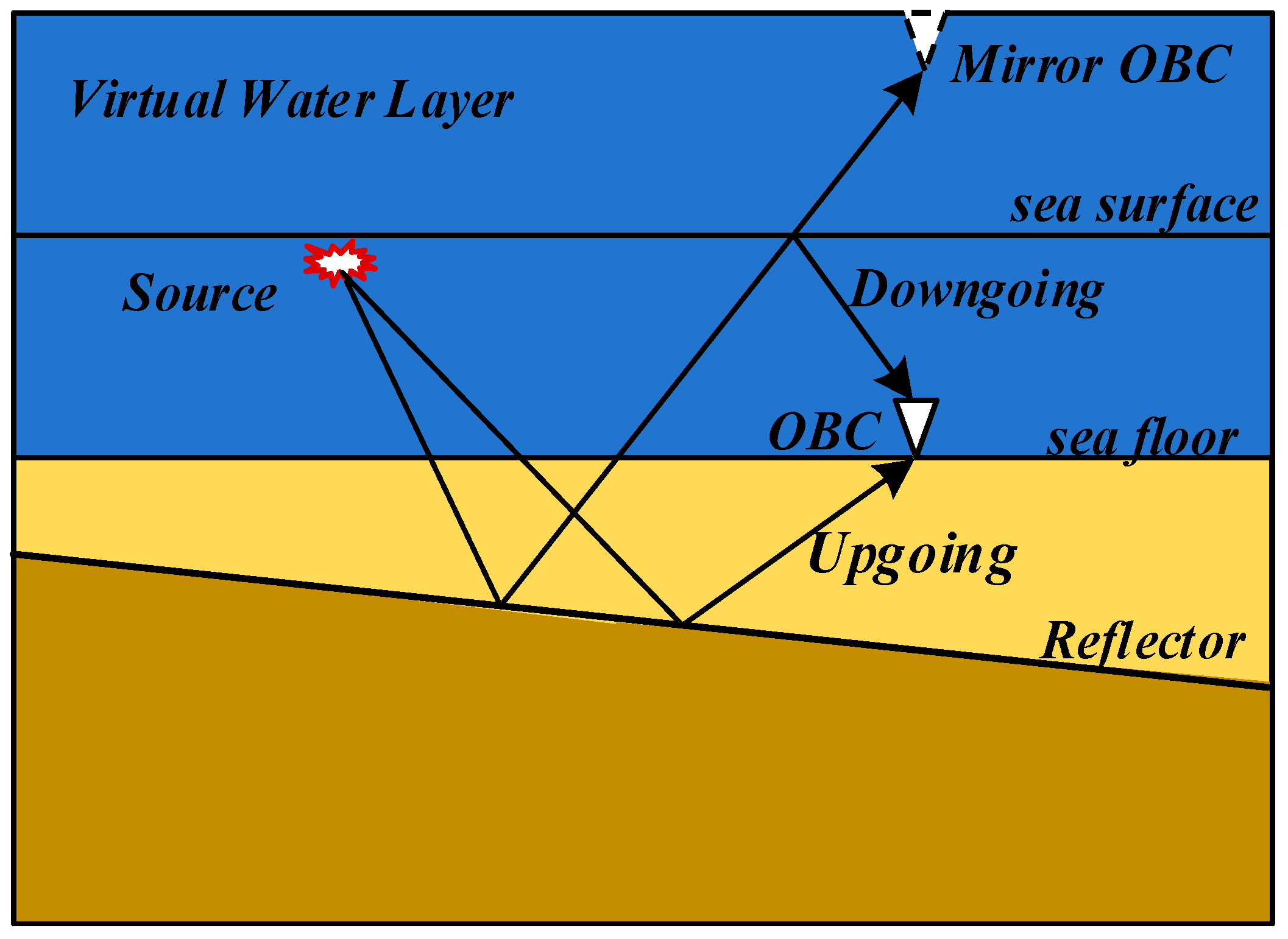
Figure 1. Schematic diagram of wave propagation paths, illustrating the geometric difference between the primary upgoing wave and the first-order receiver-side ghost. The blue area represents the water layer (and virtual water layer), while the yellow area represents the subsurface. The red explosion symbols indicate the seismic sources, and the white triangles represent the OBC receivers (on the seafloor) and mirrored receivers (at the top).
Jmse 13 02254 g001
Figure 2. Comparison of illumination ranges, highlighting the broader lateral subsurface coverage provided by ghost waves compared to primary reflections. (a) Illumination range of primary reflections; (b) Illumination range of receiver-side ghost waves. The red lines on the reflector interface indicate the extent of the subsurface illumination coverage.
Jmse 13 02254 g002
Figure 3. Decomposition of the wave path. (a) One full-wave propagation in the global domain, and (b) separated sequential simulations in subdomains. Solid black lines indicate wave propagation paths. Red dashed arrows indicate the injection of wavefields at virtual boundaries. The red star represents the seismic source, and the inverted triangles represent the OBC receivers on the seafloor.
Jmse 13 02254 g003
Figure 4. Sketches of the proposed PSF calculation strategy. The red lines represent the wave propagation paths associated with the central point of the PSF, and the green lines represent the propagation paths for the neighboring scattering points.
Jmse 13 02254 g004
Figure 5. Flowchart of the proposed framework. The workflow consists of three main stages: (1) separation of ghost-wave components using the representation theorem, (2) generation of the initial blurred image via mirror migration, and (3) reconstruction of the high-resolution reflectivity image using image-domain LSM.
Jmse 13 02254 g005
Figure 6. Migration velocity model for the BSR synthetic model.
Jmse 13 02254 g006
Figure 7. PSF of the ghost wavefield for the BSR synthetic model.
Jmse 13 02254 g007
Figure 8. Compares the ghost wave imaging results before and after high-resolution mirror migration for the uplift–depression model. (a) Ghost wave mirror migration result, (b) Ghost wave high-resolution mirror migration result. The red arrows indicate the improved imaging of the steep flanks and the depression area, showing better continuity and resolution.
Jmse 13 02254 g008
Figure 9. (a) Zoomed Ghost wave mirror migration result for the uplift–depression model; (b) Zoomed Ghost wave high-resolution mirror migration result for the uplift–depression model; (c) Wavenumber spectrum of (a); (d) Wavenumber spectrum of (b).
Jmse 13 02254 g009
Figure 10. Migration velocity model for the Gullfaks model.
Jmse 13 02254 g010
Figure 11. PSF of the receiver-side ghost wavefield for the Gullfaks model.
Jmse 13 02254 g011
Figure 12. Compares the ghost wave imaging results before and after high-resolution mirror migration for the Gullfaks model. (a) Mirror migration result, and (b) high-resolution mirror migration result. The red arrows indicate areas with improved structural clarity and better-defined fault planes.
Jmse 13 02254 g012
Figure 13. (a) Zoomed Ghost wave mirror migration result for the Gullfaks model; (b) Zoomed Ghost wave high-resolution mirror migration result for the Gullfaks model; (c) Wavenumber spectrum of (a); (d) Wavenumber spectrum of (b).
Jmse 13 02254 g013
Figure 14. Migration velocity model for the Pluto model.
Jmse 13 02254 g014
Figure 15. PSF of the receiver-side ghost wavefield for the Pluto model.
Jmse 13 02254 g015
Figure 16. Compares the ghost wave imaging results before and after high-resolution mirror migration for the Pluto model. (a) Ghost wave mirror migration result, (b) Ghost wave high-resolution mirror migration result. The red arrows indicate areas where strong migration artifacts are suppressed and sub-salt reflectors are better resolved.
Jmse 13 02254 g016
Figure 17. (a) Zoomed Ghost wave mirror migration result for the Pluto model; (b) Zoomed Ghost wave high-resolution mirror migration result for the Pluto model; (c) Wavenumber spectrum of (a); (d) Wavenumber spectrum of (b).
Jmse 13 02254 g017
Disclaimer/Publisher’s Note: The statements, opinions and data contained in all publications are solely those of the individual author(s) and contributor(s) and not of MDPI and/or the editor(s). MDPI and/or the editor(s) disclaim responsibility for any injury to people or property resulting from any ideas, methods, instructions or products referred to in the content.