Article

Trajectory Planning Method for Multi-UUV Formation Rendezvous in Obstacle and Current Environments

College of Intelligent Systems Science and Engineering, Harbin Engineering University, Harbin 150001, China
*
Author to whom correspondence should be addressed.
J. Mar. Sci. Eng. 2025, 13(12), 2221; https://doi.org/10.3390/jmse13122221
Submission received: 18 October 2025 / Revised: 19 November 2025 / Accepted: 20 November 2025 / Published: 21 November 2025
(This article belongs to the Section Ocean Engineering)

Abstract

Formation rendezvous is a critical phase during the deployment or recovery of multiple unmanned underwater vehicles (UUVs) in cooperative missions, and represents one of the core problems in multi-UUV cooperative planning. In practical marine environments with obstacles and currents, multiple constraints must be simultaneously satisfied, including obstacle avoidance, inter-UUV collision prevention, kinematic limitations, and specified initial and terminal states. These requirements make energy-optimal trajectory planning for multi-UUV formation rendezvous highly challenging. Traditional integrated cooperative planning methods often struggle to obtain optimal or even feasible solutions due to the complexity of constraints and the vastness of the solution space. To address these issues, a dual-layer planning framework for multi-UUV formation rendezvous trajectory planning in environments with obstacles and currents is proposed in this paper. The framework consists of an initial individual trajectory planning layer and a secondary cooperative planning layer. In the initial individual trajectory planning stage, the Grey Wolf Optimization (GWO) algorithm is employed to optimize high-order terms of polynomial curves, generating initial trajectories for individual UUVs that satisfy obstacle avoidance, kinematic constraints, and state requirements. These trajectories are then used as inputs to the secondary cooperative planning stage. In the cooperative stage, a Self-Adaptive Particle Swarm Optimization (SAPSO) is introduced to explicitly address inter-UUV collision avoidance while incorporating all individual constraints, ultimately producing a cooperative rendezvous trajectory that minimizes overall energy consumption. To validate the effectiveness of the proposed method, a simulation environment incorporating vortex flow fields and real-world island topography was constructed. Simulation results demonstrate that the proposed hierarchical trajectory planning method is capable of generating energy-optimal formation rendezvous trajectories that satisfy multiple constraints for multi-UUV systems in environments with obstacles and ocean currents, highlighting its strong potential for practical engineering applications.

1. Introduction

In recent years, with the continued expansion of fields such as exploration, resource development, and underwater search [1], operations involving UUVs [2] have become a prominent research focus. Formation rendezvous constitutes a critical phase during the deployment or recovery stages of cooperative UUV missions and represents one of the fundamental challenges in UUVs cooperative planning. The trajectory planning for multi-UUV formation rendezvous [3] aims to generate trajectories for a group of initially dispersed UUVs from their respective starting points to a designated rendezvous location. This process requires all UUVs to arrive at the target point simultaneously at a specified time, achieve the desired formation upon convergence, and maintain consistency in motion states such as heading and velocity.
Regarding cooperative trajectory or path planning for multiple unmanned systems—such as UUVs, Unmanned Surface Vehicles (USVs), Unmanned Aerial Vehicles (UAVs), and Unmanned Ground Vehicles (UGVs)—current research efforts have predominantly concentrated on constraint management, optimization objectives, and the effective exploitation of environmental information.
Satisfying constraint conditions represents the primary consideration in formation rendezvous trajectory or path planning. These constraints typically encompass environmental limitations, vehicle-specific physical restrictions, and inter-agent relational requirements. Regarding obstacle avoidance constraints involving both static and dynamic obstacles during planning. Zhang et al. [4] proposed a two-phase UUVs rendezvous path planning method. Their approach initially employs a fusion of artificial potential field and fish swarm trust search algorithms for global planning to identify critical sub-goal points. Subsequently, for addressing unknown threats, a bidirectional Rapidly-exploring Random Tree Star (RRT*) algorithm incorporating incomplete constraint rolling optimization is adopted for local real-time replanning. Addressing UUVs cooperative path planning and collision avoidance in obstacle-rich environments. Wu et al. [5] developed a novel algorithm integrating Artificial Potential Field (APF) with A* search. By introducing inter-vehicle repulsive forces and temporary virtual target points, their method effectively resolves the local minimum problem inherent to traditional Artificial Potential Field (APF) methods, while leveraging the A* algorithm to ensure path feasibility in complex obstacle configurations. For constrained navigation through narrow spatial passages, Xing et al. [6] presented an enhanced deep reinforcement learning scheme. Their solution incorporates an LSTM-enhanced MATD3 network, a novel dense reward function, and hierarchical training mechanism, significantly improving formation adaptability for UAVs. To address multi-task point access problems constrained by complex urban road networks and diversified mission durations, Yang et al. [7] developed an Ant Colony Optimization (ACO) based coordinated path planning method for truck-mounted UAV swarms, incorporating kinematic constraints and mission time limitations. Their methodology first computes optimal UGV paths satisfying road network constraints, then discretizes them into docking points where optimal paths are planned for UAV swarms to visit multiple mission points. Concerning inter-agent constraints within clusters, Ma et al. [8] established an online cooperative obstacle avoidance path planning method for AUVs. Their approach considers both temporal and spatial coordination aspects by establishing information sharing mechanisms to obtain real-time path data for coordination requirement assessment, with specifically formulated cooperative avoidance strategies ensuring spatiotemporal safety constraints among Autonomous Underwater Vehicle (AUV) clusters. Under comprehensive constraints including terrain threats, radar exposure, UAV turning angles, maximum flight distance, and altitude limitations, Geng et al. [9] implemented crucial improvements to traditional Particle Swarm Optimization (PSO) by introducing opposition-based learning mechanisms. This strategy significantly enhances algorithmic search efficiency and global exploration capability, enabling rapid convergence to superior flight paths while strictly satisfying multiple complex constraints.
The objectives of cooperative path and trajectory planning vary significantly depending on the specific mission context [10]. Y. Volkan et al. [11] proposed an improved Genetic Algorithm (GA) solution. Their approach incorporated revisit time intervals and multiple runway strategies to enhance planning efficiency and feasibility in complex scenarios. With optimization objectives focusing on path length under constraints including minimum and maximum flight range, altitude limitations, and maximum turning angle. Lu et al. [12] developed an Adaptive Differential Evolution (ADE) method to address modeling complexity and computational intensity in UAVs cooperative trajectory planning. For cooperative implementation, they adopted a distributed framework where PSO-ADE handles individual trajectory planning tasks, with trajectory feedback incorporated into the PSO velocity update formula to guide particle movement direction through cooperative path optimization. Luo et al. [13]. proposed a self-adaptive optimization method considering key objectives including flight duration, path length, and energy consumption. Their methodology first constructs a multi-objective planning model centered on these core parameters, then designs an adaptive optimization algorithm enabling UAVs to autonomously select optimal paths through real-time adjustment of search step sizes and weight distributions. Anikó Kopacz et al. [14], for the Multi Robot Path Planning (MPP) problem, collision free obstacles and collisions are used as constraints, and the shortest path is also taken as the optimization objective. A hybrid method combining A adaptive path planning and local search has been proposed. On the basis of ensuring the optimality of path search, this method extends to multi-agent scenarios through heuristic strategies to plan collision free optimal paths for multiple robots in a static environment. This study focuses on static conditions and does not consider other dynamic environments. V. H. A. Nguyen et al. [15], take the length of the entire path as the optimization objective and add an optimization term for the smoothness of the path. Propose an improved RRT algorithm that combines the advantages of RRT PSO and Informed RRT*, and adopts a trapezoidal turning optimization strategy to replace path corners, significantly improving path smoothness and robot motion feasibility. Similarly, it is based on a completely static environment. In multi-system cooperative planning, the strategic utilization of environmental elements as active resources has emerged as a novel research direction. For AUV operations in current environments, Gong et al. [16] modeled current influences as longitudinal and lateral velocity components affecting AUV navigation, while incorporating trajectory length into energy consumption optimization objectives. Their approach employs ant colony optimization to resolve multi-trajectory planning problems, enabling flexible trajectory selection for AUVs according to specific mission metrics. Addressing the energy disparity challenge in airborne UAV formation rendezvous caused by varying initial potential energy under diverse wind conditions, Wang et al. [17] proposed a wind energy harvesting strategy integrated into collective trajectory planning. Through analysis of tailwind, headwind, no-wind, and crosswind scenarios, their method enhances solution efficiency via simplified collocation and intelligent initialization strategies, enabling individual members to compensate for energy costs through independent wind energy harvesting while planning respective trajectories. For AUVs cooperative operations in marine environments with multiple vortex currents and obstacles, Li et al. [18] developed a hybrid algorithmic framework combining K-means preprocessing, distributed auction-based task allocation, and Deep Neural Network (DNN) path planning. This methodology integrates path length with current compliance to modulate neuronal activity intensity during post-allocation path planning, significantly improving mission execution effectiveness in complex scenarios. Wang et al. [19] proposed a method for assigning intersection points and planning formation intersection trajectories based on dynamic parameter particle swarm optimization (DPPSO) to optimize polynomial trajectories has been proposed. Taking into account kinematic constraints, collision avoidance constraints between clusters, and other constraints, the energy optimization objective is to minimize the cumulative trajectory length. However, obstacle avoidance constraints and energy consumption requirements of ocean currents were not included in the evaluation of trajectory planning. Shao [20] et al. To meet the kinematic constraints of maximum curvature and continuous path curvature for unmanned aerial vehicles (UAVs), and considering collision avoidance constraints between obstacles and clusters, a path planning method based on pH curve was proposed. The distributed collaborative particle swarm optimization (DCPSO) algorithm with elite preservation strategy was adopted to generate a safe and flight path for each UAV.
Previous studies have rarely comprehensively considered multiple constraint conditions and utilized environmental flow fields to achieve energy optimal collaborative trajectory or path planning. At the same time, when various constraints and optimization terms are coupled with each other, there is room for improvement in this area of research To address this gap, this paper proposes a dual-layer planning framework for multi-UUV formation rendezvous trajectory planning in environments with obstacles and currents. This method decouples the complex multi-UUV trajectory planning problem into two sequential phases: initial individual trajectory planning layer and a secondary cooperative planning layer, effectively separating individual and collaborative trajectory planning, ultimately generating formation rendezvous trajectories that satisfy all constraints while achieving optimal energy consumption.
The remainder of this paper is organized as follows: Section 2 formulates the multi-UUV formation rendezvous problem and specifies the corresponding constraints and optimization objectives. Section 3 presents the core methodology of this work—the dual-layer planning framework. Section 4 provides a detailed exposition of the initial individual trajectory planning approach. Section 5 introduces the secondary cooperative trajectory planning approach. Section 6 presents and analyzes the simulation results. Finally, Section 7 concludes the paper with a summary and concluding remarks.

2. Problem Statement

2.1. Preliminaries

This study investigates the trajectory planning problem for formation rendezvous of UUVs in environments with obstacles and currents. Consider a UUV numbered i with an initial state q i S = ( x i S , y i S , u i S , v i S , ψ i S ) at the initial point and a terminal state q i E = ( x i E , y i E , u E , v E , ψ E ) at the terminal point, where ( x , y ) denotes the UUV position, ( u , v ) represents the surge and sway velocity, and ψ denotes the heading angle. The trajectory planning problem involves determining a set of trajectories γ i ( t ) connecting the initial and terminal points, which is mathematically formulated as:
q i S = ( x i S , y i S , u i S , v i S , ψ i S ) γ i ( t ) q i E = ( x i E , y i E , u E , v E , ψ E )
where represents the constraints during the formation rendezvous process, including initial and terminal state constraints, obstacle avoidance constraints, inter-UUV collision avoidance constraints, and kinematic constraints. As illustrated in Figure 1, the trajectory planning problem is exemplified using a system of three UUVs operating in an environment with multiple obstacles and currents. The blue arrow in Figure 1 represents the direction of the current, the red curve represents the trajectory of the UUV, Obs represents obstacles in the environment, the green line represents the minimum distance, and d s a f e represents the safe distance of the UUV. UUV1, UUV2, and UUV3 are initially located at distinct initial points with different initial states q 1 S , q 2 S , and q 3 S . After rendezvous time T , they arrive at their respective rendezvous points ( x 1 ( T ) , y 1 ( T ) ) , ( x 2 ( T ) , y 2 ( T ) ) , and ( x 3 ( T ) , y 3 ( T ) ) , achieving consistent and identical motion states ( u E , v E , ψ E ) .

2.2. Constraints

The trajectory planning for multi-UUV formation rendezvous must simultaneously satisfy multiple stringent constraints, which can be categorized into the following key aspects:
(1)
Formation rendezvous initial and terminal state constraints
In UUVs formation rendezvous, the initial states of individual UUVs are typically dispersed. The rendezvous process requires all UUVs to reach their designated rendezvous points within the specified time T while achieving consensus in velocity vectors and heading angles to form the prescribed formation configuration [21].
(2)
Obstacle avoidance
In environments containing obstacles and currents, although obstacles exhibit diverse geometries, they can all be approximated using finite grids [22]. During the UUVs formation rendezvous process, no trajectory points p i ( t ) of any UUV shall intersect with obstacle grids, which can be formulated as:
t [ 0 , T ] , p i ( t ) W , p i ( t ) ( m , n ) ο G m , n
In the mathematical formulation, ο denotes the complete obstacle index set, W defines the entire map domain boundaries, and G m , n specifically represents the precise grid region corresponding to index ( m , n ) , formally as G m , n = [ m Δ x , ( m + 1 ) Δ x ) ] × [ n Δ y , ( n + 1 ) Δ y ) ] .
(3)
Inter-UUV collision avoidance constraints
During the UUVs formation rendezvous process, collision risks between UUVs must be thoroughly considered [23]. Given the formation rendezvous UUV set U , at any time instant t , the position of UUVs is p i ( t ) , the distance between any two distinct UUVs i and j must exceed the minimum safe distance d s a f e , formulated as:
t [ 0 , T ] , d i j = p i ( t ) p j ( t ) > d s a f e , i , j U
Based on the comprehensive consideration of navigation positioning uncertainty, control dynamic characteristics, and system safety redundancy, this article sets a safety distance dimension of 40 m.
(4)
Kinematic constraints
To enhance the feasibility of formation rendezvous trajectory planning [24], it is essential to account for the kinematic constraints of UUVs, including velocity constraints and heading angular velocity constraints. The planning framework of this study is based on a basic control assumption, that is, when the speed of the UUV is within the range of 1 to 6 knots, its propulsion system and underlying controller can provide sufficient control torque and steering effect, thereby ensuring that the UUV has stable and accurate tracking ability for the longitudinal velocity u and lateral velocity v generated by the plan.
All UUVs must comply with these constraint conditions.
V M i n u 2 + v 2 V M a x
where V M i n and V M a x denote the minimum and maximum velocity constraints of the UUV. The value of V M i n is 0.6 m/s, The value of V M a x is 3 m/s. For the turning angular velocity r of UUV, it also satisfies:
r r M a x
where r M a x represents the maximum turning rate of the UUV.

2.3. Problem Formulation

The multi-UUV cooperative trajectory planning problem can be formulated as an optimization problem [25], As mentioned in reference [24], the concept of multi-objective optimization is to achieve the ideal value of the objective function to be optimized while satisfying multiple constraint conditions. The research content of this article is to achieve formation rendezvous of multi-UUV systems within a specified time limit with the goal of optimal energy consumption, while satisfying all constraints during the rendezvous process and planning the rendezvous trajectory γ i o p t ( t ) reasonably.
UUVs typically carry power batteries with limited capacity. Their navigation energy consumption E, is mainly reflected in the power consumption term, P p r o p and heading time T of the propulsion system, which is calculated by E T P p r o p d t . Propulsion power P p r o p is mainly used to overcome water resistance F r e s which is related to velocity and head in angle relative to the surrounding current. Therefore, this article considers the Voyage length and the angle between the UUV and the direction of the current as factors affecting energy consumption. To support this approach conceptually, power consumption models that similarly relate dynamic and kinematic variables to the battery load are available [26].
The core of this article lies in the trajectory planning method, with a focus on verifying the effectiveness of the proposed method in environments where obstacles and ocean currents coexist. Therefore, based on the above propulsion system energy consumption model, we transform it into an expression form of influencing factors, that is selecting trajectory length and current energy expenditure as components of the objective function J , which facilitates the generation of energy-optimal formation rendezvous trajectories. The multi-UUV cooperative trajectory planning problem can be mathematically formulated as follows:
J ( γ i o p t ( t ) ) = m i n a 1 i 0 T u 2 + v 2 d t + a 2 i F i C u r , s . t . ( 2 ) ( 4 ) , i U
where a 1 and a 2 are weighting coefficients, and F i C u r represents the current compliance degree of the trajectory for UUV i , specifically calculated as:
F i C u r = k = 1 N ε Δ ψ i ( k ) u 2 ( k ) + v 2 ( k ) ,   0 ° < Δ ψ i ( k ) < 9 0 ° k = 1 N Δ ψ i ( k ) u 2 ( k ) + v 2 ( k ) ,   9 0 ° < Δ ψ i ( k ) < 180 °
where Δ ψ i ( k ) represents the angle between the heading direction of UUV i and the current direction at the k -th trajectory point, while u ( k ) and v ( k ) denote the surge and sway velocity components induced by the current at the k -th trajectory point, respectively. ε is the reward factor, this article takes 0.01. According to Equation (7), a UUV is considered to be leveraging the current for enhanced energy efficiency when a smaller acute angle between its heading and the current direction leads to a greater resultant velocity. Therefore, the energy consumption values mentioned in the subsequent sections of this article and in the table (such as Table 3) are normalized dimensionless values calculated according to this model and do not have physical units. Intended as a unified comparative indicator for subsequent comparative analysis.

3. Dual-Layer Planning Framework

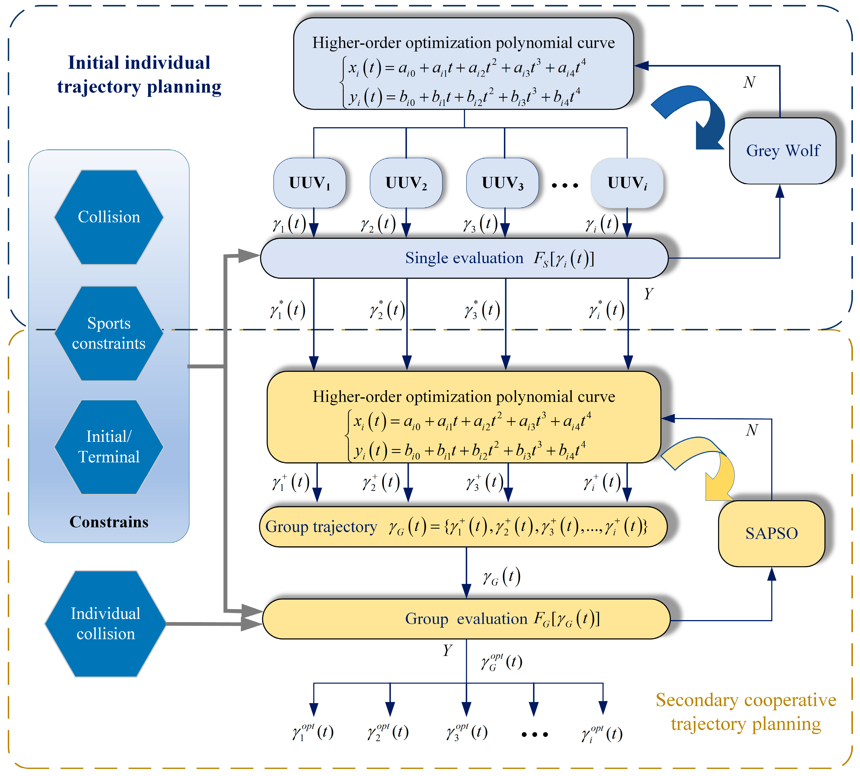
This section is the core part of the article, aiming to achieve decoupling of various constraints and optimization objectives in the planning of individual and cluster trajectories in UUV rendezvous trajectory planning. Conventional integrated cooperative planning methods typically address all motion constraints and optimization objectives for multi-UUV trajectories at a single level [19]. However, in marine environments where obstacles and currents coexist, the pursuit of energy-optimal solutions under multiple coupled constraints—including obstacle avoidance, inter-UUV collision prevention, kinematic limitations, and terminal rendezvous consistency—renders the formation rendezvous trajectory planning problem highly complex. These high-dimensional, strongly constrained optimization problems impose significant computational burdens and are prone to local optima, often failing to yield feasible solutions that satisfy all constraints within limited timeframes. These limitations severely restrict the practical applicability of such methods in marine environments. Therefore, this article transforms the complex multi-objective optimization problem mentioned above into the hierarchical optimization problem mentioned in reference [24]. Divide the optimization objectives and constraints during the formation rendezvous process into two planning layers: individual and group. This paper proposes a dual-layer planning framework for multi-UUV formation rendezvous trajectory planning. The initial individual trajectory planning layer generates input information for the secondary cooperative planning layer. In the secondary collaborative planning layer, as the rendezvous trajectories of each UUV are fine tuned, emphasis is placed on considering collision avoidance constraints between groups, while also taking into account all individual constraint terms such as starting and ending point state constraints. For any set of trajectories that do not meet the UUV constraint conditions, they should all be discarded and iteratively searched for the next set of trajectories that can meet them. All “optimizable individual trajectories” should be synchronized and optimized as a whole “cluster trajectory”. This is the core idea of ensuring that all team rendezvous constraints are met. The overall architecture is illustrated in Figure 2.
The proposed dual-layer planning framework consists of an upper initial individual trajectory planning layer and a lower secondary cooperative planning layer. The core idea is to separate individual constraints from group constraints, with optimal energy consumption as the optimization objective. The second layer (collaborative planning) serves as the upper layer optimization, with the goal of coordinating the solutions (individual trajectories) provided by the lower layer to meet the constraints and objectives of the formation. In the initial individual trajectory planning layer, the trajectory γ i ( t ) of each individual UUV is input into the single-UUV trajectory evaluation function F S [ γ i ( t ) ] , and the GWO algorithm is employed to optimize high-order terms of polynomial curves. This generates initial single-UUV trajectories γ i * ( t ) that aim for energy optimality while satisfying obstacle avoidance, kinematic constraints, and state requirements, which then serve as input information for the secondary cooperative planning layer. In the secondary cooperative planning layer, in addition to maintaining the constraints from the single-UUV trajectory planning phase, inter-UUV collision avoidance constraints are additionally considered. Based on the optimal individual trajectories γ i * ( t ) of each UUV, the secondary layer correspondingly generates new optimizable individual trajectories γ i + ( t ) . Subsequently, during the formation rendezvous trajectory planning process, all optimizable individual trajectories γ i + ( t ) are simultaneously optimized as a collective cluster trajectory γ G ( t ) = { γ i + ( t ) , γ i + ( t ) , , γ i + ( t ) } , where all UUV trajectories collectively form the optimization variables instead of single UUV trajectories, and are input into the secondary cooperative UUV trajectory evaluation function F G [ γ G ( t ) ] . The SAPSO algorithm is then applied for iterative optimization to obtain the optimal collective formation rendezvous trajectory γ G o p t ( t ) , from which the optimal rendezvous trajectories for each individual UUV { γ 1 o p t ( t ) , γ 2 o p t ( t ) ,   , γ i o p t ( t ) } are derived. This is the difference between the methods used in this article and other literature such as [19], which no longer consider multiple constraints and optimization conditions at the same level, but instead achieve decoupling of constraints and optimization in individual and group planning.

4. Initial Layer for Individual UUV Polynomial Trajectory Planning Optimized by GWO

This section presents the trajectory planning methodology for the initial individual trajectory planning layer. The layer integrates the GWO with high-order polynomial curves, targeting energy-optimal performance while addressing UUV-specific constraints. The optimization results serve as critical inputs to the secondary cooperative planning layer, establishing the foundation for subsequent coordinated trajectory planning.

4.1. Polynomial Trajectory Design

Considering that the UUV system must satisfy strict motion state constraints at both the initial and terminal points, polynomial curves with continuous differentiability characteristics [27] are selected for trajectory construction. Meanwhile, the planning method for high-order polynomial trajectory curves essentially involves planning a continuous and differentiable trajectory curve. The high-order differentiability inherent in this curve ensures the continuity of the derivative of each order of the trajectory, making it highly user-friendly for the control system of UUVs. By adjusting the values of high-order terms, precise control over key motion parameters such as heading angular velocity and velocity can be achieved, enabling the trajectories to fulfill various constraints and optimization requirements.
The trajectory γ i t of a UUV numbered i can be represented by a high-order power series in discrete mathematical space, expressed as:
γ i t = k = 0 M i a k t k
For formation trajectory planning, the order of the trajectory power series is typically determined by the following boundary conditions:
M i = d S + d E + 1
where d S and d E represent the higher-order derivatives of the boundary constraints at the initial point and terminal point in point-to-point trajectory planning, respectively. Considering the following boundary conditions:
x i t S = x i S ,   y i t S = y i S x ˙ i t S = x ˙ i S ,   y ˙ i t S = y ˙ i S x i t E = x i E ,   y i t E = y i E x ˙ i t E = x ˙ i E ,   y ˙ i t E = y ˙ i E
This article imposes constraints on velocity and heading at the starting and ending points, From this, it can be concluded that d S =   d E = 1 , meaning the highest-order term M i of the polynomial trajectory is of order 3. Therefore, the trajectory planning for the UUV in the horizontal plane can be derived using the following formula:
x t = a 0 + a 1 t + a 2 t 2 + a 3 t 3 y t = b 0 + b 1 t + b 2 t 2 + b 3 t 3
Based on this foundation, a fourth-order high-degree optimization term is incorporated into the trajectory of UUV numbered i , as follows:
x i t = a i 0 + a i 1 t + a i 2 t 2 + a i 3 t 3 + a i 4 t 4 y i t = b i 0 + b i 1 t + b i 2 t 2 + b i 3 t 3 + b i 4 t 4
Substituting the boundary conditions from Equation (10) into the expression, where t S and t E represent the start time and end time respectively, we obtain:
x i t S = a i 0 + a i 1 t S + a i 2 t S 2 + a i 3 t S 3 + a i 4 t S 4 = x i S x ˙ i t S = a i 1 + 2 a i 2 t S + 3 a i 3 t S 2 + 4 a i 4 t S 3 = x ˙ i S x i t E = a i 0 + a i 1 t E + a i 2 t E 2 + a i 3 t E 3 + a i 4 t E 4 = x i E x ˙ i t E = a i 1 + 2 a i 2 t E + 3 a i 3 t E 2 + 4 a i 4 t E 3 = x ˙ i E
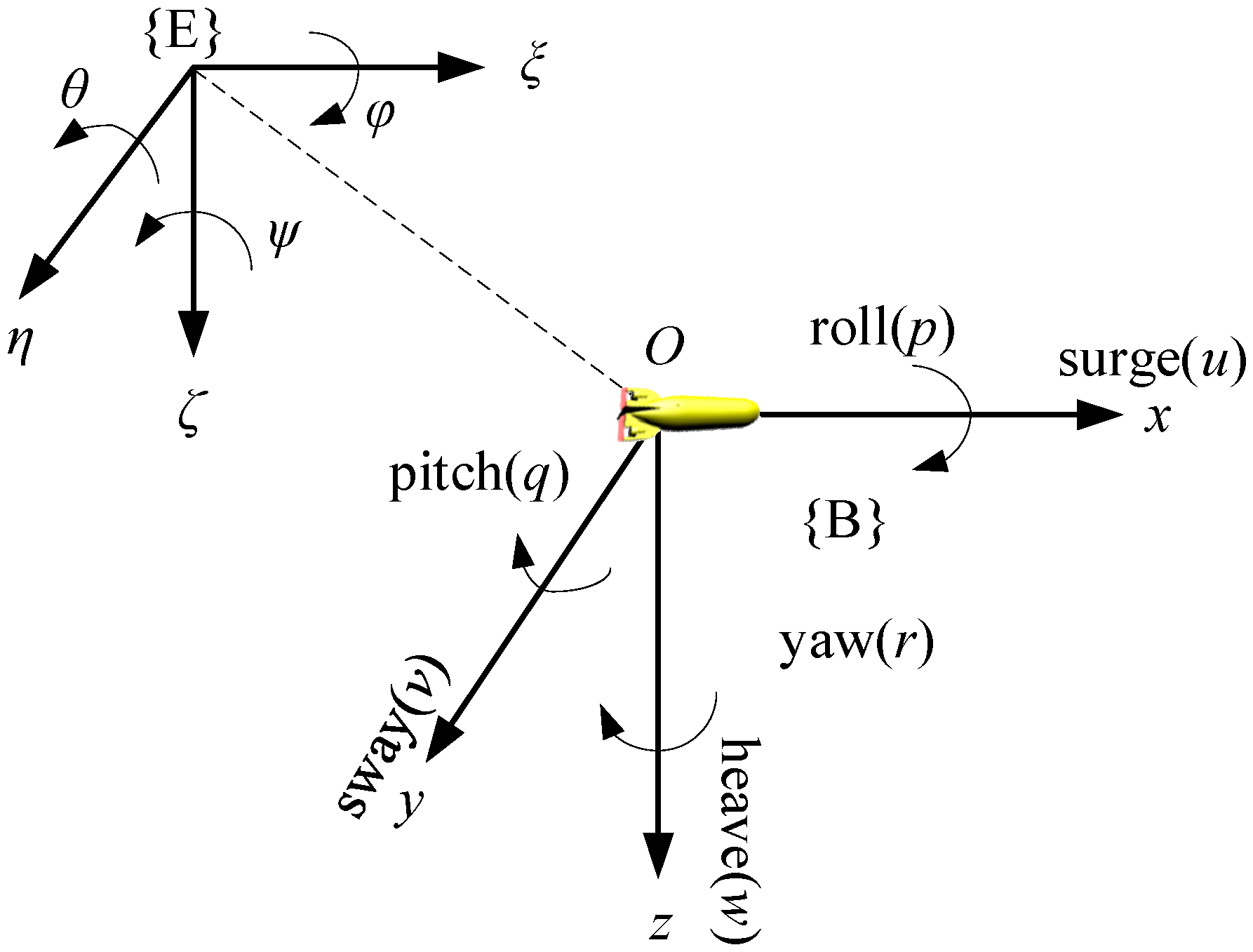
This article abstracts each UUV as a particle (i.e., its geometric center point) for processing. The conversion relationship between the UUV carrier coordinate system and the fixed coordinate system is shown in Figure 3 [28]. The fixed coordinate system is represented as { B } , and the carrier coordinate system is represented as { E } . The simplified underactuated horizontal plane UUV kinematic model [19] is adopted as follows:
x ˙ = u c o s ψ ν s i n ψ y ˙ = u s i n ψ + ν c o s ψ ψ ˙ = r
where x and y represent the position coordinates of the UUV in the global coordinate system, ψ denotes the heading angle, ψ ˙ is the heading angular velocity. In the carrier coordinate system of UUV, u and v indicate the surge and sway velocities of the UUV, respectively. By using Formula (14) for coordinate transformation, the geodetic coordinate system and the carrier coordinate system are connected, providing a unified standard for the planning of various UUVs.
Substituting the model into Equation (13) yields:
x i t S = a i 0 + a i 1 t S + a i 2 t S 2 + a i 3 t S 3 + a i 4 t S 4 = x i S x ˙ i t S = a i 1 + 2 a i 2 t S + 3 a i 3 t S 2 + 4 a i 4 t S 3 = u i S cos ψ i S v i S sin ψ i S x i t E = a i 0 + a i 1 t E + a i 2 t E 2 + a i 3 t E 3 + a i 4 t E 4 = x i E x ˙ i t E = a i 1 + 2 a i 2 t E + 3 a i 3 t E 2 + 4 a i 4 t E 3 = u i E cos ψ i E v i E sin ψ i E
Solving the above equation,
1 t S t S 2 t S 3 0 1 2 t S 2 3 t S 2 1 t E t E 2 t E 3 0 1 2 t E 2 3 t E 2 a i 0 a i 1 a i 2 a i 3 = x i S a i 4 t S 4 u i S cos ψ i S v i S sin ψ i S 4 a i 4 t i S 3 x i E a i 4 t E 4 u i E cos ψ i E v i E sin ψ i E 4 a i 4 t i E 3
Since a i 4 represents the optimization term coefficients with known numerical values, the expression for x i t can be derived. Using the same methodology and substituting accordingly, [ b i 0 , b i 1 , b i 2 , b i 3 , b i 4 ] can be determined, yielding the expression for y i t .

4.2. Initial Monomer UUV Trajectory Planning

This subsection achieves optimal formation rendezvous trajectory planning by encoding trajectory parameters in the GWO and guiding the population to emulate hunting behavior through iterative optimization.

4.2.1. Grey Wolf Optimizer

The GWO [29] is a metaheuristic algorithm that simulates the leadership structure and cooperative hunting mechanisms of grey wolf packs. The algorithm classifies the population into four hierarchical levels: α , β , δ , θ , modeling the encircling and attacking phases of wolf pack behavior mathematically.
(1)
The grey wolf encircling process
The core of the GWO Algorithm lies in the movement of grey wolves, which is represented in mathematical space as:
X t + 1 = X p t A D D = C X p t X t
where t denotes the current iteration number, A and C are coefficient vectors, X p t represents the position vector of the prey, and X t indicates the position vector of the grey wolf at the t iteration. The coefficient vectors A and C are computed as follows:
A = 2 a r 1 a C = 2 r 2
where r 1 and r 2 are random values within the range 0 , 1 . To simulate the process of gradually approaching the prey, A represents a random vector within the interval a , a , where the value of a decreases linearly from 2 to 0 as the number of iterations increases.
(2)
Grey wolf attacking process
To mathematically abstract the attacking behavior of grey wolves [30], within the entire population, the α , β , δ wolves serve as leaders that guide the hunting activities of the lower-level wolves. They are considered closest to the prey. The other grey wolves are influenced by them and conduct search and attack operations based on their positions. Similarly, the α , β , δ wolves update their positions based on information from the other wolves, as illustrated in Figure 4.
In Figure 4, the α , β , δ wolves possess distinct random values and consequently maintain different distances to the θ wolves. For the other θ grey wolves, the position information generated under the influence of the α , β , δ wolves are expressed as:
X 1 = X α A 1 D a X 2 = X β A 2 D β X 3 = X δ A 3 D δ
where X 1 , X 2 , and X 3 represent the position information generated by the influence of the α , β , δ wolves on the θ level wolves, respectively; D a , D β , and D δ denote the distances between other grey wolves and the α , β , δ wolves, respectively, expressed as:
D α = C 1 X α X D β = C 2 X β X D δ = C 3 X δ X
where C 1 , C 2 , and C 3 represent random values, and X denotes the current position of the θ grey wolf. Finally, by averaging the position information influenced by the α , β , δ wolves, the final adjusted position of the θ grey wolf is obtained as:
X t + 1 = X 1 + X 2 + X 3 3

4.2.2. Trajectory Planning Process

The core of the initial individual trajectory planning lies in integrating the GWO with the high-order polynomial curve method. This is achieved by employing the GWO to search for optimal values within the defined ranges of parameters a i 4 and b i 4 , thereby adjusting the UUV’s trajectory curve. The specific procedural steps are as follows:
(1)
Grey wolf population model
Let the grey wolf population size be N . The grey wolf model Γ selects the high-order optimization term Γ i ( k ) = [ a i 4 ( k ) , b i 4 ( k ) ] ,   k = 1 , 2 , 3 N for the k -th trajectory γ i t of UUV i , with a value range of [ ( a i M i n , a i M a x ) , ( b i M i n , b i M a x ) ] . Let Z denote the mapping from the high-order optimization term to the trajectory, as referenced in Equation (15), expressed as:
Z [ Γ i ( k ) ] = Z [ ( a i 4 ( k ) , b i 4 ( k ) ) ] = γ i ( t ) ( k )
(2)
Population initialization
Initialize the θ wolf in the population as:
θ = { Γ i ( 1 ) , Γ i ( 2 ) , Γ i ( 3 ) , , Γ i ( k ) } , k = 1 , 2 , 3 N
where the value of Γ i ( k ) is assigned as follows:
Γ i ( k ) = ( a i 4 ( k ) , b i 4 ( k ) ) = a i 4 ( k ) = a i M i n + ξ ( a i M a x a i M i n ) b i 4 ( k ) = b i M i n + ξ ( b i M a x b i M i n )
ξ satisfies a normal distribution within the interval (0, 1). The corresponding single-UUV trajectory evaluation function J S ( θ ) for the initial θ wolf is then given by:
J S ( θ ) = { J S [ Z ( Γ i ( 1 ) ) ] , J S [ Z ( Γ i ( 2 ) ) ] , , J S [ Z ( Γ i ( k ) ) ] } ,   k = 1 , 2 , 3 N
From the initialized θ wolves, three grey wolves— J i ( α ) , J i ( β ) , and J i ( δ ) —are selected based on the criterion of minimal evaluation function values, serving as the α , β , δ wolves that represent the three optimal trajectories in the current single-UUV trajectory planning, namely:
J S [ γ i t ( α ) ] < J S [ γ i t ( β ) ] < J S [ γ i t ( δ ) ] J S [ γ i t ( k ) ] ,   k α β δ s . t . ( 2 ) , ( 4 ) ( 5 )
(3)
Iterative optimization
After one iteration, the three optimal trajectories are selected as the current best trajectories— Z [ Γ i i t e r ( α ) ] , Z [ Γ i i t e r ( β ) ] , and Z [ Γ i i t e r ( δ ) ] . Following the encircling and attacking process of the GWO, these guide the update of the θ wolf positions Γ i i t e r + 1 ( k ) in the next iteration. This process continues until the maximum number of iterations is reached, at which point the optimal trajectory for UUV i is derived based on the optimal high-order optimization terms Γ i o p t .

5. Cooperative Layer for Multi-UUV Polynomial Trajectory Planning Optimized by SAPSO

This section introduces the secondary cooperative planning layer within the dual-layer planning framework. Building upon the initial single-UUV trajectories, this study further incorporates the SAPSO algorithm for secondary cooperative trajectory planning. Aiming to minimize energy consumption, the secondary cooperative planning layer comprehensively considers individual UUV constraints while emphasizing collision avoidance among multiple UUVs.

5.1. SAPSO

The performance of the PSO algorithm [31] is inherently constrained by its control parameters. Traditional static parameter configurations exhibit significant adaptability limitations—they are prone to premature convergence from insufficient early-stage exploration and limited convergence precision from inadequate late-stage exploitation. The SAPSO algorithm proposed in this study addresses these issues by establishing an iteration-aware mechanism that enables dynamic parameter adjustment. This approach achieves optimal balance between exploration and exploitation in the solution space through real-time parameter modulation. The parameter update strategy for the particle swarm is detailed as follows.
(1)
Adaptive inertia weight adjustment
The inertia weight ω , as a key parameter in the PSO [32], determines the degree to which a particle retains its previous velocity. When ω is set to a larger value, particles tend to maintain their original motion state, enhancing global exploration capability; when ω is set to a smaller value, particles become more influenced by individual and global optimal solutions, facilitating local refinement. The update formula is as follows:
ω k = ω s t a r t ω s t a r t ω e n d 2 t T t T 2
where ω s t a r t and ω e n d represent the initial and terminal inertia weight, respectively.
(2)
Adaptive learning factor adjustment
The learning factors c 1 and c 2 are critical parameters in the PSO. Excessively large c 1 values cause particles to over-rely on individual experience and trap them in local search, while disproportionately large c 2 values drive premature convergence toward the swarm’s global best solution. Therefore, during initial iterations, the strategy employs relatively large c 1 and small c 2 values, then linearly decreases c 1 while increasing c 2 throughout the optimization process to guide particles toward the global optimum.
c 1 t = c 1 i n i + c 1 f i n c 1 i n i t T
c 2 t = c 2 i n i + c 2 f i n c 2 i n i t T
where c 1 t represents the value of the individual learning factor at the t-th iteration, c 1 i n i denotes the initial value of c 1 at the start of iteration, c 1 f i n indicates the terminal value of c 1 at the end of iteration, while c 2 t , c 2 i n i , and c 2 f i n follow analogous definitions.
(3)
Adaptive velocity factor parameter adjustment
During the iterative process of the PSO algorithm, the value of the velocity factor ρ critically influences optimization performance. Adopting a larger ρ in the early iterations enhances the global search capability of particles, while a smaller ρ in later stages facilitates refined local search, thereby improving solution accuracy.
ρ t = ρ m a x ρ m i n + exp γ t T 2 + ρ i n t
where ρ m a x and ρ m i n represent the maximum and minimum values of the velocity factor, respectively, ρ i n t denotes the initial value of the velocity factor, and γ serves as the velocity factor parameter.

5.2. Secondary Cooperative Trajectory Planning Process

Secondary cooperative trajectory planning extends the initial single UUV planning by incorporating inter-UUV collision avoidance constraints while maintaining the energy-optimal objective, thereby holistically addressing all operational constraints.
(1)
Particle Swarm Model
Let the optimization population size be N . The particle model selects S ( k ) . Unlike the optimization population model in the initial single UUV planning, this layer no longer treats the high-order optimization terms a i 4 ( k ) and b i 4 ( k ) of a single UUV trajectory γ i t as the optimization object. Instead, it considers the set of high-order optimization terms corresponding to all UUV trajectories participating in the formation rendezvous as a single optimization particle, denoted as S ( k ) .
S ( k ) = [ ( a 14 ( k ) , b 14 ( k ) ] , [ ( a 24 ( k ) , b 24 ( k ) ] , [ ( a 34 ( k ) , b 34 ( k ) ] , [ ( a i 4 ( k ) , b i 4 ( k ) ] ,   i = 1 , 2 , 3 , , U
(2)
Population initialization
Unlike the single UUV trajectory planning, the optimization object during initialization no longer selects values from a fixed range as in Formula (24). Instead, it leverages the optimal results from the single UUV trajectories, where Γ i + represents the high-order optimization terms for each UUV trajectory generated based on the optimal single UUV trajectories. The initialization is performed as follows:
S ( k ) = ( Γ 1 + ( k ) , Γ 2 + ( k ) , , Γ i + ( k ) = Γ 1 + ( k ) = 0.5 Γ 1 o p t + 0.5 ξ Γ 1 o p t Γ 2 + ( k ) = 0.5 Γ 2 o p t + 0.5 ξ Γ 2 o p t Γ i + ( k ) = 0.5 Γ i o p t + 0.5 ξ Γ i o p t i = 1 , 2 , , U k = 1 , 2 , 3 , , N
Equation (32) indicates that after obtaining the high-order optimization terms Γ i o p t for each UUV trajectory optimized in the initial layer, new optimizable terms Γ i + are randomly generated within a small range. This approach enables fine-tuning of the trajectory curves while satisfying the single UUV constraint conditions, thereby further fulfilling inter-UUV distance constraints and achieving decoupling between single UUV trajectory planning and swarm trajectory planning.
The collective trajectory is subsequently evaluated using the swarm trajectory evaluation function, expressed as:
J G ( Z [ S ( k ) ] ) = { J G [ γ 1 t ( k ) ] , J G [ γ 2 t ( k ) ] , , J G [ γ i t ( k ) ] } , i = 1 , 2 , , U ,   k = 1 , 2 , 3 , N ,   s . t . ( 2 ) ( 5 )
(3)
Optimization process of SAPSO
After one iteration, the locally optimal particle S * ( k ) is selected from all N particles in the current generation, corresponding to the rendezvous trajectories { γ * 1 t ,   γ * 2 t ,   γ * 3 t ,     γ * i t } of each UUV participating in the formation rendezvous. Guided by the particle swarm movement rules, the particles of the next generation are updated. After recalculating the evaluation function, the optimal rendezvous trajectory Z [ S o p t ( k ) ] = { γ 1 o p t t ,   γ 2 o p t t ,   γ 3 o p t t ,     γ i o p t t } for each UUV is ultimately obtained.

6. Simulation Verification

To validate the effectiveness of the proposed dual-layer planning framework for multi-UUV formation rendezvous trajectory planning, this section presents simulation experiments. Initially, a realistic marine environment with coexisting obstacles and currents is constructed. A 3 km × 3 km satellite map of a selected area in the East China Sea is utilized to create a grid-based map model [33] using the grid method. Subsequently, a current model is established based on the classical Lamb dipole vortex model, which accurately captures key characteristics of full-range intensity variations in practical currents. The impact of vortex flow is abstracted as surge and sway velocity components u c and v c generated at specific points.
u C c 0 = S y y 0 2 π ( c c 0 ) 2 1 e ( c c 0 ) 2 R 2
v C c = S x x 0 2 π ( c c 0 ) 2 1 e ( c c 0 ) 2 R 2
ω ( c ) = S π R 2 e ( c c 0 ) 2 R 2
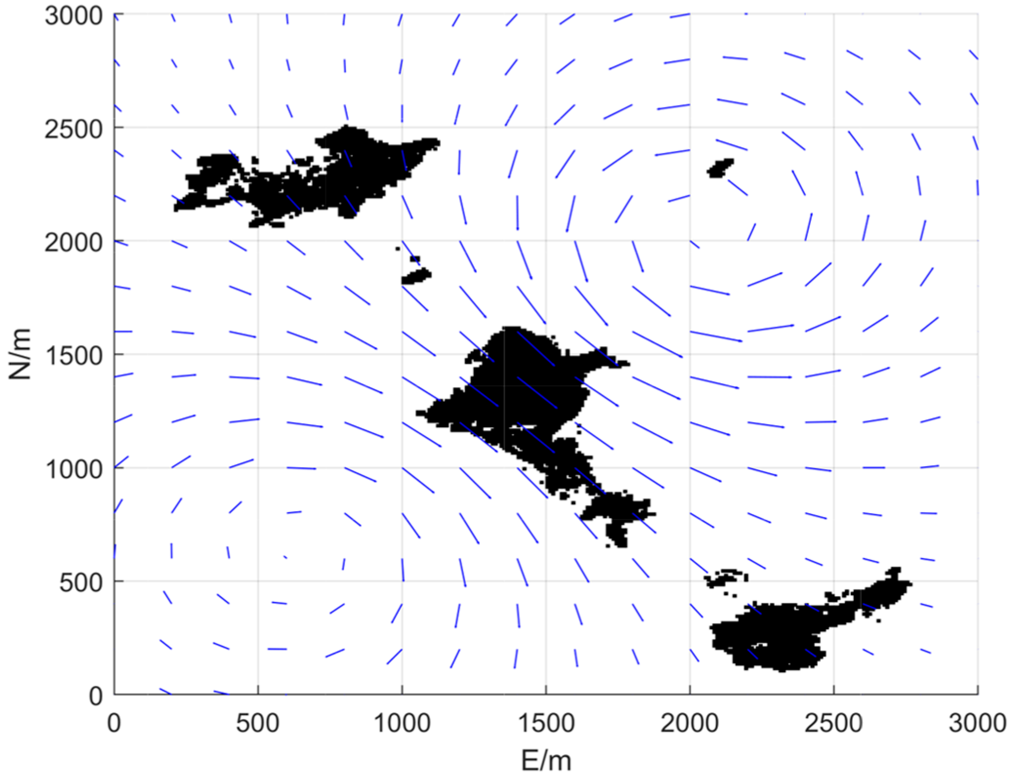
Assume the constant value of the eddy current intensity S 1 in the first vortex field is 1000, with an effective radius R 1 of 500, and the vortex center is located at (750 m, 750 m). For the second vortex field, the constant value of vortex intensity S 2 is 1200, with an effective radius R 2 of 400 m, and the vortex center is positioned at (2000 m, 2000 m). The plotting scale is set to 300 m, meaning currents are visualized at 300 m intervals. The obstacles and current environments constructed in this article are shown in Figure 5, where black areas represent obstacles and blue arrows represent currents.
Assume five UUVs are deployed to execute a formation rendezvous mission, to form a pentagonal formation at the designated area. The relevant rendezvous boundary conditions are specified in Table 1, and the associated parameter configurations are detailed in Table 2, Among them, values without units are constant parameters.
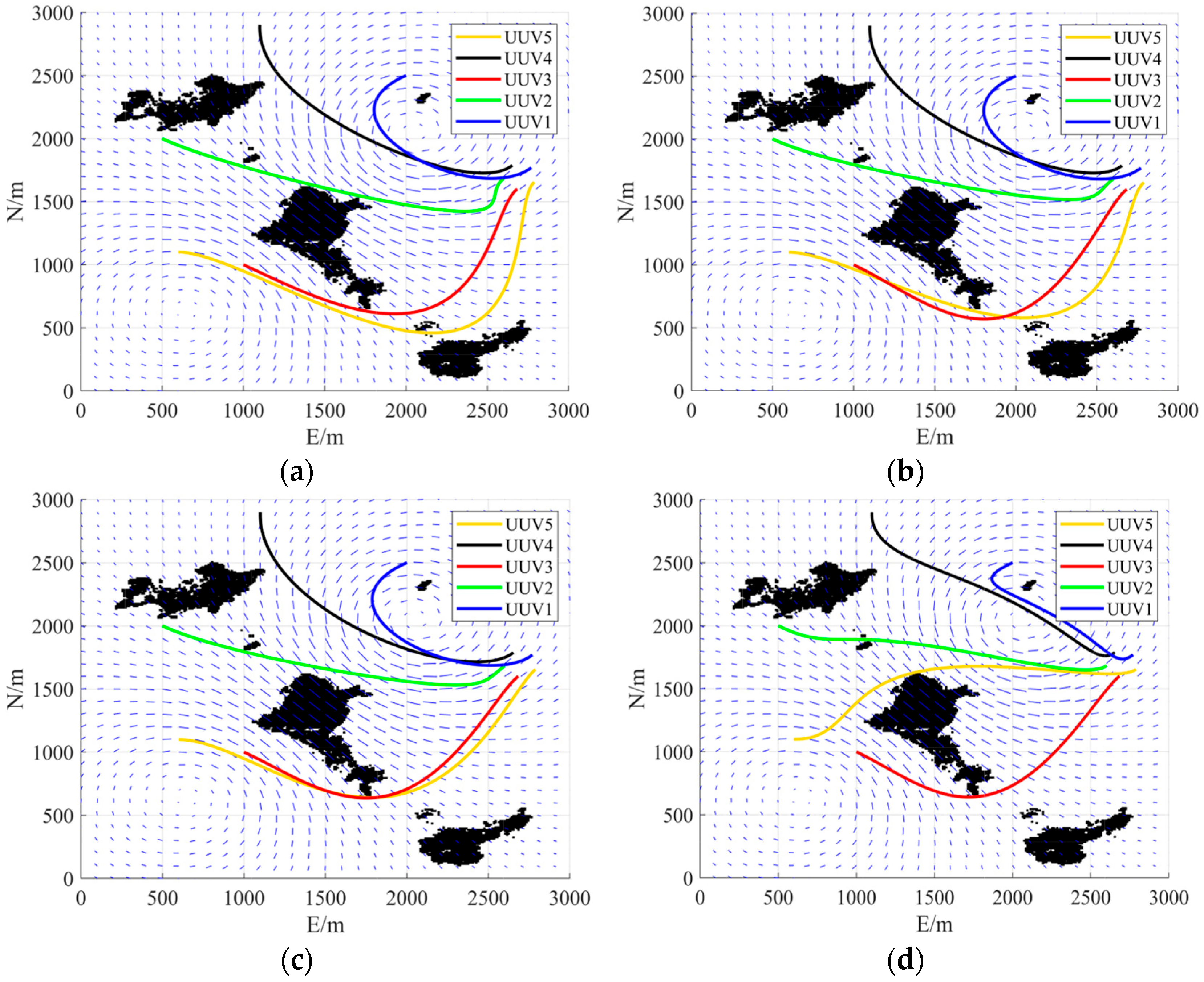
Considering the four cases presented in the table, four simulation experiments were conducted to validate the dual-layer formation rendezvous trajectory planning method under different weighting coefficient scenarios. The simulation results are shown in Table 3.
Table 3. Evaluation results of trajectory length and current energy consumption.
CaseTrajectory LengthCurrent Energy Consumption Value
Case 111.61 × 10³ m6.26 × 103
Case 211.31 × 10³ m7.16 × 103
Case 311.01 × 10³ m8.65 × 103
Case 410.11 × 10³ m20.74 × 103
Considering the four cases presented in the table, four simulation experiments were conducted to validate the dual-layer formation rendezvous trajectory planning method under different weighting coefficient scenarios. The simulation results are shown in Table 3.
As shown in Figure 6 and Table 3, the energy consumption values of currents in Table 3 are normalized dimensionless values without physical units and are used for subsequent comparative analysis. with the progressive increase in the weighting coefficient for UUV trajectory length, trajectory length increasingly dominates the planning process. Simultaneously, the formation rendezvous trajectory of the UUVs aligns with the current direction to achieve energy conservation objectives.
In Case 1, where the trajectory length proportion is minimized at 50%, the configuration achieves the optimal current energy consumption evaluation value among Cases 1–4.
As the trajectory length weighting increases to 75% in Case 2, the total trajectory distance shortens from 11.63 × 10³ in Case 1 to 11.31 × 10³, accompanied by noticeable modifications in the trajectory curvature. Consequently, the corresponding energy consumption attributed to currents changes to 7.16 × 10³.
In Case 3, with the trajectory length weighting set at 83%, the UUV trajectory becomes noticeably shorter in the graphical representation, and the specific trajectory length value decreases to 11.01 × 10³. Meanwhile, the energy consumption evaluation value for currents increases as the trajectory length weighting grows, indicating a reduced compliance with currents.
In Case 4, where the trajectory length weighting reaches 100% and thus completely disregards current factors, the resulting trajectory achieves the shortest possible length but corresponds to the worst current energy consumption evaluation value, recorded as 20.74 × 10³.
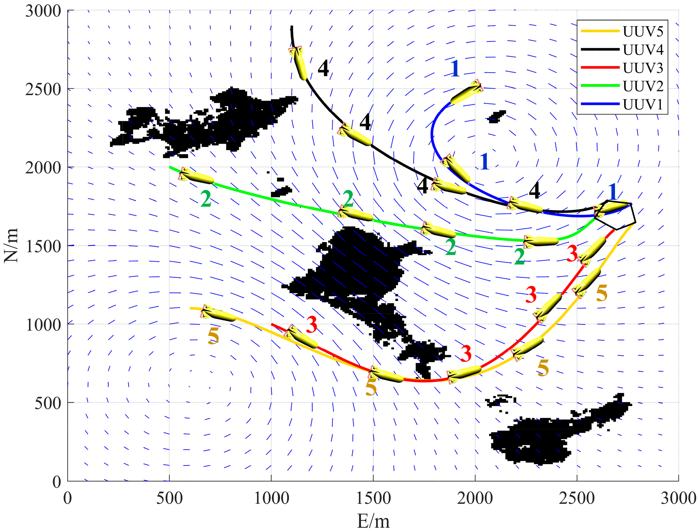
The subsequent analysis of constraint conditions and optimization results will be based on the outcomes from Case 3.
As shown in Figure 7, the number represents the number of the UUV and is distinguished by color. All UUVs depart from their initial points without colliding with obstacles and arrive at their designated rendezvous positions to form a pentagonal formation. To better visualize the minimum distance between each UUV, let d min ( i , t ) represent the minimum distance between the i -th UUV and any other j -th UUV at any time t , with the specific expression given by Formula (37).
d min ( i , t ) = m i n i j d ( i , j , t ) , i , j U
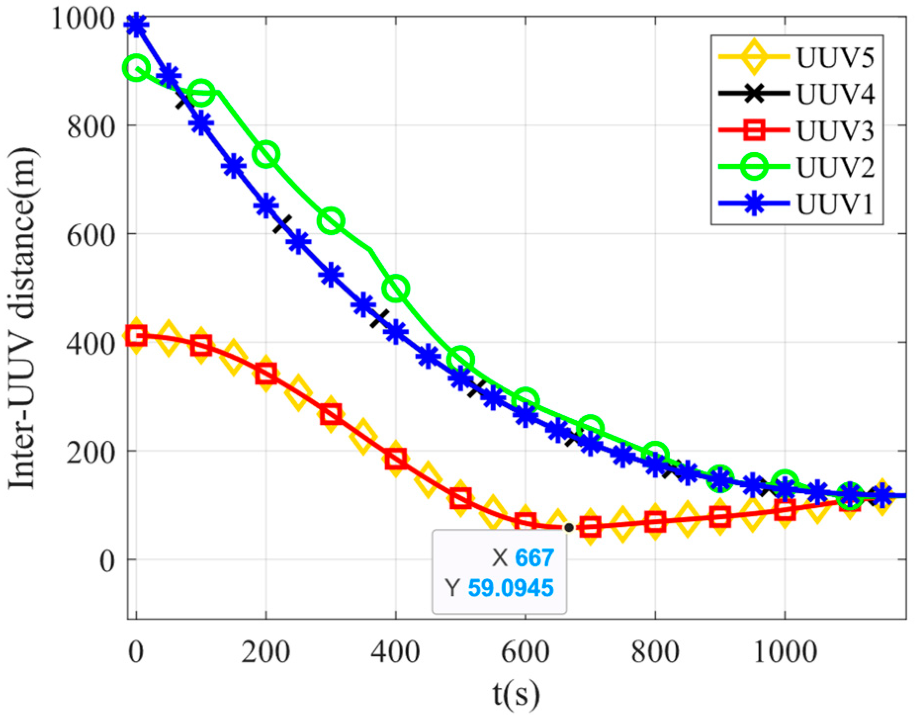
As shown in Figure 8, the vertical axis Inter-UUV distance(m) represents the minimum distance from each UUV to the other UUVs, and the vertical axis represents time(s). The minimum distance between any two UUVs is 59.10 m, and at any given moment, all inter-UUV distances exceed the predefined safety threshold d s a f e .
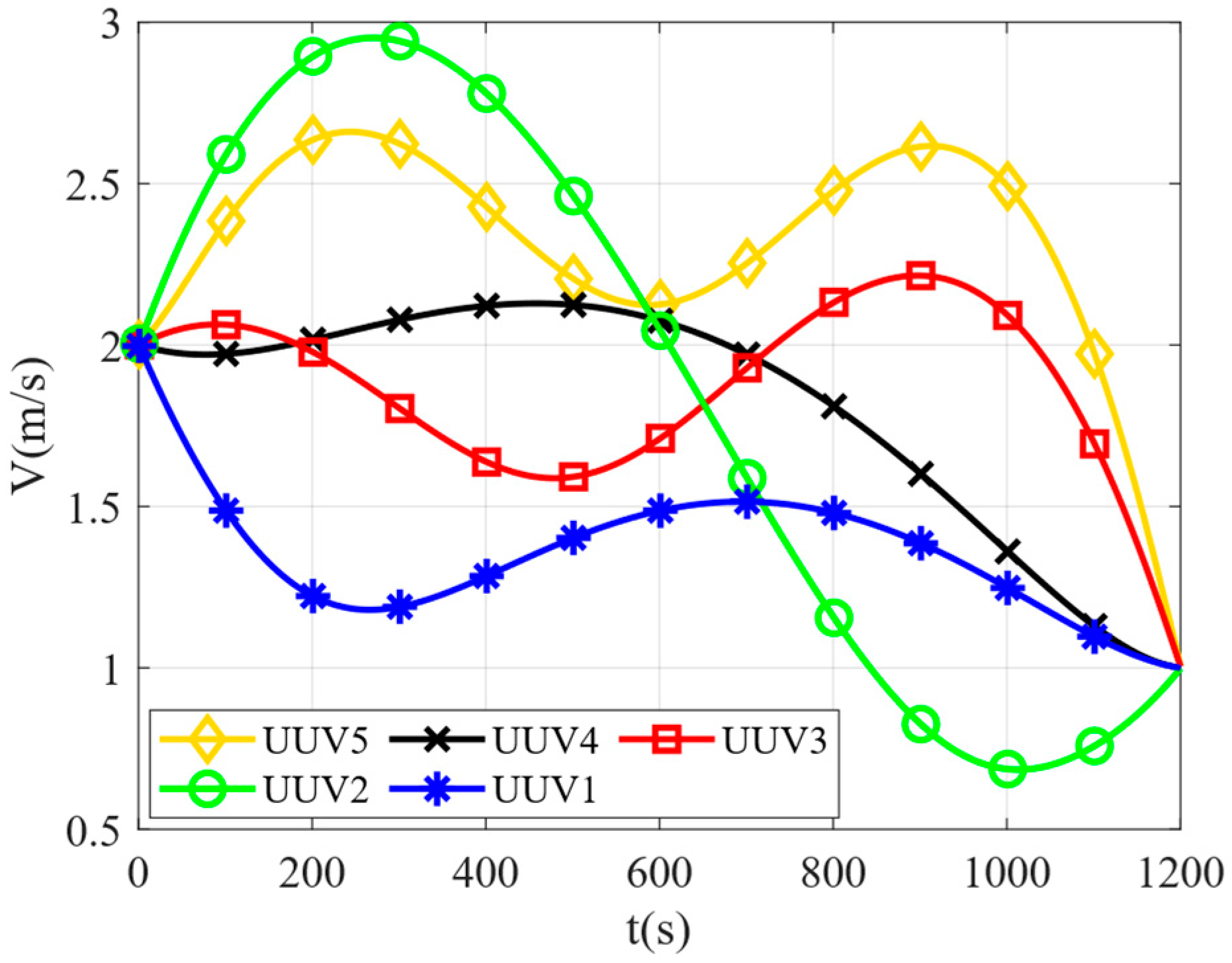
As shown in Figure 9, The vertical axis represents the navigation speed(m/s) of UUV, the vertical axis represents time(t). The velocities of all UUVs range between 0.68 m/s and 2.95 m/s, which aligns with the achievable speed range of UUVs. Upon reaching the rendezvous points, all UUVs achieve the preset desired velocities, satisfying the velocity constraints at the rendezvous points.
According to Figure 10, the horizontal axis represents angular velocity r(°/s), and the vertical axis represents time(t). The maximum heading angular velocity observed among all UUVs is 0.46°/s, demonstrating compliance with the turning motion constraints in their trajectories.
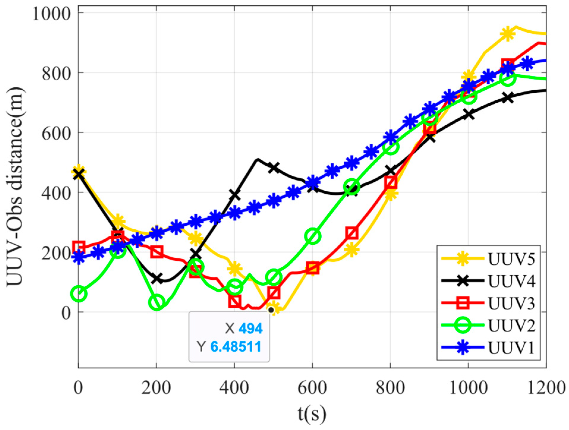
Figure 11 displays the minimum distances from each UUV to all obstacle grids. The vertical axis UUV-Obs distance(m) represents the minimum distance from each UUV to the obstacles, and the vertical axis represents time(s). The UUV5 maintains the closest proximity to obstacles with a minimum distance of 6.45 m, confirming that all UUVs successfully avoid collisions with obstacles.
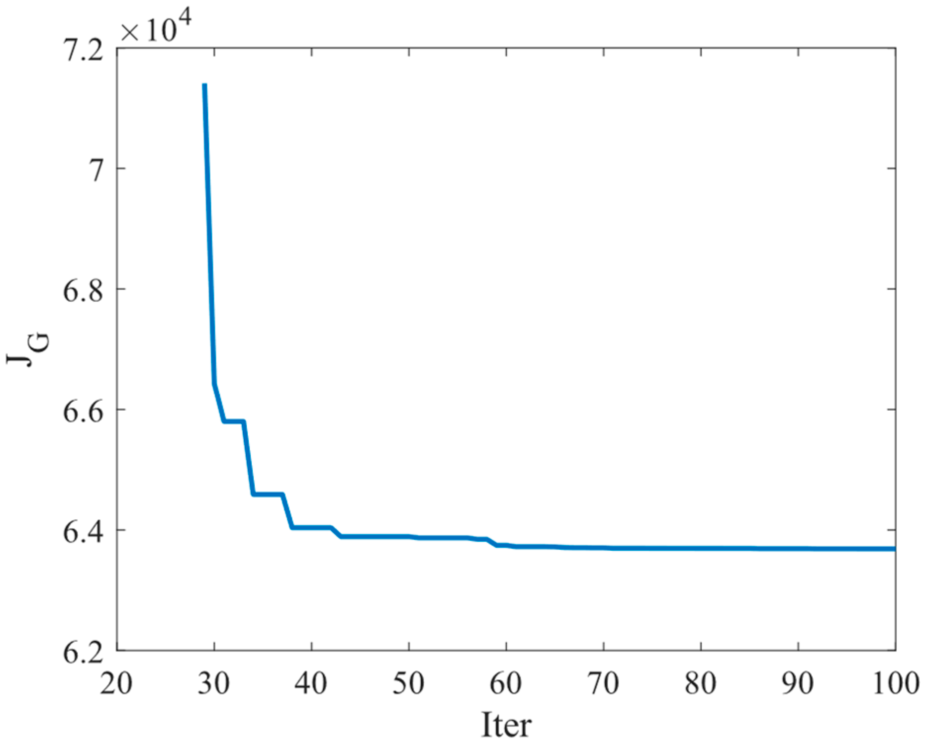
During the simulation, the predefined optimization objective function served as the evaluation criterion for the SAPSO algorithm. When the algorithm iterated until the evaluation function converged to a stable minimum value, this indicated that the high-order optimization terms yielding the optimal objective function had been obtained, thereby determining the optimal formation rendezvous trajectory for the multi-UUV system.
As shown in Figure 12, the algorithm ultimately converged to solution 6.36 × 10⁴. The comprehensive analysis of these results verifies the feasibility of the obtained formation rendezvous trajectory.
In the simulation experiment, we found that we discussed a key unexpected finding: in the ocean current environment, simply pursuing the geometric shortest path (i.e., assigning excessive weight to the “trajectory length” in our method) can actually lead to a significant increase in total energy consumption. In contrast, by taking reasonable values for length and energy consumption, UUVs can be guided to plan moderately circuitous trajectories that can effectively “leverage” the ocean current, thereby achieving better energy consumption performance globally.

7. Conclusions

Formation rendezvous trajectory planning represents a critical challenge in multi-UUV system coordination, particularly in environments with obstacles and currents. The core complexity lies in simultaneously addressing multiple constraints including obstacle avoidance, inter-UUV collision prevention, kinematic limitations, and rendezvous timing synchronization, while maintaining energy-optimal performance as the primary objective. This paper systematically investigates this problem and innovatively proposes a dual-layer planning framework for cooperative trajectory planning.
This method decouples the conventional integrated cooperative planning problem into two hierarchical stages: initial individual trajectory planning and secondary cooperative trajectory planning. In the initial planning layer, the GWO is employed to optimize high-order polynomial curves, comprehensively considering multiple objectives including obstacle avoidance, kinematic constraints, collision prevention, and energy consumption. This process generates initial trajectories for each UUV, serving as inputs to the cooperative layer. In the secondary cooperative planning layer, building upon the initial trajectory information, the SAPSO algorithm performs coordinated exploration within the solution space, ultimately producing globally optimal formation rendezvous trajectories that satisfy all constraint conditions.
Simulation results demonstrate that the proposed dual-layer planning method effectively handles multiple constraints, generating formation rendezvous trajectories that satisfy velocity and angular velocity constraints while ensuring collision avoidance between UUVs and between UUVs and obstacles. Furthermore, by adjusting the weighting coefficients for currents and trajectory length, the method achieves coordinated optimization of UUVs trajectories to minimize energy consumption. These findings validate the effectiveness and superiority of the proposed approach in addressing the multi-UUV formation rendezvous trajectory planning problem.
The current research of the article focuses on verifying the use of a two-layer optimization method to solve the problem of obstacle and multi-UUV rendezvous trajectory planning in the current environment. In practical applications, based on the research in this article, more attention should be paid to the feasibility of planning and real-time planning time to evaluate whether the planning effect is ideal. A broader comparison with general and state-of-the-art multi-layer optimization techniques is an important research direction for the future. In future research, we will increase ocean experiments to consider the impact of the ocean on the solid hull control of unmanned underwater vehicles, while also increasing the number of UUVs performing tasks. Through three-dimensional trajectory planning, we will study the impact of different optimization methods on the overall efficiency of task execution, in order to further improve its engineering practicality.

Author Contributions

Conceptualization, T.C. and K.W.; methodology, T.C. and K.W.; software, K.W.; validation, T.C., K.W. and Q.W.; formal analysis, T.C., K.W. and Q.W.; investigation, T.C. and K.W.; resources, T.C. and K.W.; data curation, T.C. and K.W.; writing—original draft preparation, K.W.; writing—review and editing, T.C., K.W. and Q.W.; visualization, T.C. and K.W.; supervision, Q.W.; project administration, T.C.; funding acquisition, T.C. All authors have read and agreed to the published version of the manuscript.

Funding

This research was funded by the Youth Support Program of China under Grant 002040130635, and in part by the National Natural Science Foundation of China under Grant 52101347.

Data Availability Statement

The original contributions presented in the study are included in the article, further inquiries can be directed to the corresponding author.

Conflicts of Interest

The authors declare no conflicts of interest.

References

  1. Martynova, L.; Pashkevich, I.; Bykova, V. Development of a Digital Twin of an Autonomous Underwater Vehicle to Assess the Effectiveness of Searching for Bottom Objects. In Proceedings of the 2024 International Russian Smart Industry Conference (SmartIndustryCon), Sochi, Russia, 25–29 March 2024; pp. 243–248. [Google Scholar]
  2. Luo, N.; Wang, H.; Huang, S.; Gao, W.; Zhong, B.; Huang, Y.; Li, B. Multi-UUV Dynamic Cooperative Task Planning Method Based on Multi-Objective Genetic Algorithm. In Proceedings of the 2023 62nd IEEE Conference on Decision and Control (CDC), Singapore, 13–15 December 2023; pp. 8836–8843. [Google Scholar]
  3. Xun, Y.; Liu, Y.; Wang, Y.; Fan, Z.; Xu, H.; Ma, S. Formation Assembly and Transformation Controller of Multi-UAV based on Sliding Mode Control. In Proceedings of the 2024 36th Chinese Control and Decision Conference (CCDC), Xi’an, China, 25–27 May 2024; pp. 142–148. [Google Scholar]
  4. Zhang, W.; Zhang, K.; Li, Y.; Han, P. Research on Multi-UUV Path Planning Method Based on Recycling Task. In Proceedings of the OCEANS 2022, Hampton Roads, VA, USA, 7–20 October 2022; pp. 1–7. [Google Scholar]
  5. Wu, X.; Long, X.; Yuan, S.; Hu, Q.; Xie, P. Multi-UUV Coordinated Path Planning with Collision Avoidance (CPP/CA) Based on Combination of Improved APF and A*. In Proceedings of the 2022 8th International Conference on Control, Automation and Robotics (ICCAR), Xiamen, China, 8–10 April 2022; pp. 218–223. [Google Scholar]
  6. Xing, X.; Zhou, Z.; Li, Y.; Xiao, B.; Xun, Y. Multi-UAV Adaptive Cooperative Formation Trajectory Planning Based on an Improved MATD3 Algorithm of Deep Reinforcement Learning. IEEE Trans. Veh. Technol. 2024, 73, 12484–12499. [Google Scholar] [CrossRef]
  7. Yang, S.; Yu, J.; Zhang, Z.; Zhao, G. Cooperative Path Planning Method Based on Road Network Constraints for Vehicle-Mounted Multi-Rotor UAV Swarm. In Proceedings of the 2023 42nd Chinese Control Conference (CCC), Tianjin, China, 24–26 July 2023; pp. 1779–1784. [Google Scholar]
  8. Ma, X.; Chen, W.; Sun, R.; Cao, J. Online Collaborative Obstacle Avoidance Path Planning Based on Multi-AUV. In Proceedings of the 2023 9th International Conference on Mechanical and Electronics Engineering (ICMEE), Xi’an, China, 17–19 November 2023; pp. 340–345. [Google Scholar]
  9. Geng, L.; Dong, C.; Han, J.; Jia, J.; Zhao, R. Unmanned Aerial Vehicle Path Planning Based on Inverse Learning Strategy Particle Swarm Optimization Algorithm. In Proceedings of the 2025 IEEE 20th Conference on Industrial Electronics and Applications (ICIEA), Yantai, China, 3–6 August 2025; pp. 1–5. [Google Scholar]
  10. Qu, J.; Li, X.; Sun, G. Optimal Formation Configuration Analysis for Cooperative Localization System of Multi-AUV. IEEE Access 2021, 9, 90702–90714. [Google Scholar] [CrossRef]
  11. Pehlivanoğlu, Y.V.; Bekmezci, İ; Pehlivanoğlu, P. Efficient Strategy for Multi-UAV Path Planning in Target Coverage Problems. In Proceedings of the 2022 International Conference on Theoretical and Applied Computer Science and Engineering (ICTASCE), Istanbul, Turkey, 29 September–1 October 2022; pp. 110–115. [Google Scholar]
  12. Lu, L.; Dai, J.; Ying, J. Distributed multi-UAV cooperation for path planning by an NTVPSO-ADE algorithm. In Proceedings of the 2022 41st Chinese Control Conference (CCC), Hefei, China, 25–27 July 2022; pp. 5973–5978. [Google Scholar]
  13. Luo, R. Design of Multi-Objective Path Planning for UAV Based on Adaptive Optimization. In Proceedings of the 2024 6th International Conference on Frontier Technologies of Information and Computer (ICFTIC), Qingdao, China, 13–15 December 2024; pp. 717–720. [Google Scholar]
  14. Kopacz, A.; González, E.G.; Chira, C.; Flecha, J.R.V. Hybrid Adaptive Greedy Algorithm Addressing the Multi-Robot Path Planning Problem. IEEE Lat. Am. Trans. 2025, 23, 856–864. [Google Scholar] [CrossRef]
  15. Nguyen, V.H.A.; Tuong, V.C.; Nguyen, T.T.T.; Le, T.M.; Tran, H.M.; Wang, K.; Tran, L.V.; Dao, S.V.T. ITE-RRT*: Intelligent Path Planning for Autonomous Cars with Intermediary Trees, Triangle Inequality, and Equal Distance Optimization. IEEE Access 2025, 13, 192958–192980. [Google Scholar] [CrossRef]
  16. Gong, Y.J.; Huang, T.; Ma, Y.N.; Jeon, S.W.; Zhang, J. MTrajPlanner: A Multiple-Trajectory Planning Algorithm for Autonomous Underwater Vehicles. IEEE Trans. Intell. Transp. Syst. 2023, 24, 3714–3727. [Google Scholar] [CrossRef]
  17. Wang, X.; Ma, T.; Zhang, L. Rendezvous Trajectory Planning for Air-Launched UAV Swarms Using Wind Energy. IEEE Access 2024, 12, 168531–168546. [Google Scholar] [CrossRef]
  18. Li, H.; Chen, M. Task allocation and path planning problems of multi-AUV system based on auction-dynamic neural network. In Proceedings of the 2023 35th Chinese Control and Decision Conference (CCDC), Yichang, China, 20–22 May 2023; pp. 2945–2949. [Google Scholar]
  19. Wang, Q.; Xu, D.; Liu, X.; Zhang, G.; Han, Z. Trajectory Planning Method for Formation Rendezvous of Underactuated Multi-UUV Under Multiple Constraints. J. Mar. Sci. Eng. 2024, 12, 2118. [Google Scholar] [CrossRef]
  20. Shao, Z.; Yan, F.; Zhou, Z.; Zhu, X. Path Planning for Multi-UAV Formation Rendezvous Based on Distributed Cooperative Particle Swarm Optimization. Appl. Sci. 2019, 9, 2621. [Google Scholar] [CrossRef]
  21. Singh, P.; Kumar, V.; Maurya, H.L.; Kamath, A.K. Velocity Estimator and Twisting Control Based Formation of Mobile Robots in Presence of Delay. In Proceedings of the 2023 IEEE 3rd International Conference on Smart Technologies for Power, Energy and Control (STPEC), Bhubaneswar, India, 10–13 December 2023; pp. 1–6. [Google Scholar]
  22. Louda, S.; Karkar, N.; Seghir, F.; Refoufi, S. Mobile Robot Path Planning Based on A-Star Algorithm and Artificial Potential Field Method for Autonomous Navigation. In Proceedings of the 2024 12th International Conference on Systems and Control (ICSC), Batna, Algeria, 3–5 November 2024; pp. 441–446. [Google Scholar]
  23. Muslimov, T.; Kozlov, E.; Munasypov, R. Drone Swarm Movement without Collisions with Fixed Obstacles Using a Hybrid Algorithm Based on Potential Functions. In Proceedings of the 2023 International Russian Automation Conference (RusAutoCon), Sochi, Russia, 10–16 September 2023; pp. 781–785. [Google Scholar]
  24. Ueda, Y.; Motoi, N. Local Path Planning Based on Velocity Obstacle Considering Collision Probability and Kinematic Constraint for Mobile Robot. In Proceedings of the IECON 2022–48th Annual Conference of the IEEE Industrial Electronics Society, Brussels, Belgium, 17–20 October 2022; pp. 1–6. [Google Scholar]
  25. Mejía-De-Dios, J.A.; Rodríguez-Molina, A.; Mezura-Montes, E. Multiobjective Bilevel Optimization: A Survey of the State-of-the-Art. IEEE Trans. Syst. Man Cybern. Syst. 2023, 53, 5478–5490. [Google Scholar] [CrossRef]
  26. Cebeci, C.; Grimble, M.J. Speed Tracking of an Electric Vehicle Using a Restricted Structure NGMV Control Algorithm. In Proceedings of the 2022 European Control Conference (ECC), London, UK, 12–15 July 2022; pp. 790–795. [Google Scholar]
  27. Vinayak, A.; Zakaria, M.A.; Baarath, K.; Majeed, A.P.P.A. A novel Bezier curve control point search algorithm for autonomous navigation using N-order polynomial search with boundary conditions. In Proceedings of the 2021 IEEE International Intelligent Transportation Systems Conference (ITSC), Indianapolis, IN, USA, 19–22 September 2021; pp. 3884–3889. [Google Scholar]
  28. Xu, Z.; Shen, Y.; Xie, Z.; Liu, Y. Research on Autonomous Underwater Vehicle Path Optimization Using a Field Theory-Guided A* Algorithm. J. Mar. Sci. Eng. 2024, 12, 1815. [Google Scholar] [CrossRef]
  29. Lou, L.; Zhang, H. Grey Wolf Optimization algorithm based on Hybrid Multi-strategy. In Proceedings of the 2023 8th International Conference on Intelligent Computing and Signal Processing (ICSP), Xi’an, China, 21–23 April 2023; pp. 1342–1345. [Google Scholar]
  30. Liu, Y.; Wang, J. Optimized Machine Learning Traffic Flow Prediction Model Based on Improved Gray Wolf Algorithm. In Proceedings of the 2022 7th International Conference on Intelligent Informatics and Biomedical Science (ICIIBMS), Nara, Japan, 24–26 November 2022; pp. 355–358. [Google Scholar]
  31. Bin, W. A Novel Supply Chain Multi-level Inventory Model based on Improved PSO Algorithm. In Proceedings of the 2023 8th International Conference on Communication and Electronics Systems (ICCES), Coimbatore, India, 1–3 June 2023; pp. 1733–1737. [Google Scholar]
  32. Boutalbi, O.; Seghir, F.; Boutalbi, A.; Guerra, L. A PSO-Based Global Path Planning Approach for Mobile Robots. In Proceedings of the 2024 12th International Conference on Systems and Control (ICSC), Batna, Algeria, 3–5 November 2024; pp. 354–359. [Google Scholar]
  33. Moreira, L.G.; Brandão, A.S. SLAM-Based 2D Mapping and Route Planning for Autonomous Mobile Robot Navigation. In Proceedings of the 2025 Brazilian Conference on Robotics (CROS), Belo Horizonte, Brazil, 28–30 April 2025; pp. 1–6. [Google Scholar]
Figure 1. Schematic diagram of UUV formation rendezvous.
Jmse 13 02221 g001
Figure 2. Dual-layer planning framework diagram.
Jmse 13 02221 g002
Figure 3. Schematic diagram of UUV coordinate system relationship.
Jmse 13 02221 g003
Figure 4. GWO algorithm diagram.
Jmse 13 02221 g004
Figure 5. Formation rendezvous environment diagram.
Jmse 13 02221 g005
Figure 6. Schematic diagram of trajectories of different energy consumption ratios. Among them, (a) corresponds to weighting coefficient Case 1, (b) to weighting coefficient Case 2, (c) to weighting coefficient Case 3, and (d) to weighting coefficient Case 4.
Jmse 13 02221 g006
Figure 7. Schematic diagram of formation rendezvous trajectory.
Jmse 13 02221 g007
Figure 8. Schematic diagram of distance between individual UUV.
Jmse 13 02221 g008
Figure 9. Schematic diagram of single UUV velocity.
Jmse 13 02221 g009
Figure 10. Schematic diagram of heading angular velocity of single UUV.
Jmse 13 02221 g010
Figure 11. Minimum obstacle distance diagram.
Jmse 13 02221 g011
Figure 12. Schematic diagram of optimization iteration process.
Jmse 13 02221 g012
Table 1. Formation rendezvous boundary conditions.
Point TypesPosition
x , y / m
Velocity
u , ν / ( m / s )
Heading
ψ / °
Initial points (2000, 2500)(2, 0.03)−120°
(500, 2000)(2, 0.05)120°
(1000, 1000)(2, 0.01)120°
(1100, 2900)(2, 0.06)180°
(600, 1100)(2, 0.04)90°
Terminal points (2770.7, 1770.7)(1, 0)45°
(2789.1, 1654.6)(1, 0)45°
(2584.4, 1601.2)(1, 0)45°
(2501.2, 1684.4)(1, 0)45°
(2554.6, 1789.1)(1, 0)45°
Table 2. Design of formation rendezvous parameters.
ParameterSymbolsValue
Population size N 50
Optimization iterations i t e r max 100
c 1 initial value c 1 i n i 0.5
c 1 terminal value c 1 f i n 1
c 2 initial value c 2 i n i 1.25
c 2 terminal value c 2 f i n 2.25
Maximum velocity factor ρ max 1.5
Minimum velocity factor ρ min 1
Velocity factor parameter γ 0.4
Initial velocity factor ρ int 0.4
Initial inertia weight ω s t a r t 0.9
Terminal inertia weight ω e n d 0.5
Search range S e a r c h lim (−10−8, 10−8)
Weighting coefficient a 1 , a 2 Case 1: a 1 = 1 ,   a 2 = 0
Case 2: a 1 = 1 ,   a 2 = 1
Case 3: a 1 = 1 ,   a 2 = 3
Case 4: a 1 = 1 ,   a 2 = 5
Maximum velocity constraints V M a x 3 m/s
Minimum velocity constraints V M i n 0.6 m/s
Safety distance d s a f e 40 m
Maximum angular velocity r M a x ° /s
Disclaimer/Publisher’s Note: The statements, opinions and data contained in all publications are solely those of the individual author(s) and contributor(s) and not of MDPI and/or the editor(s). MDPI and/or the editor(s) disclaim responsibility for any injury to people or property resulting from any ideas, methods, instructions or products referred to in the content.