1. Introduction
At present, the pipe-lift mining system is widely regarded as the most promising commercial deep-sea mining system worldwide, owing to its advantages of continuous operation, high mining efficiency, and relatively low energy consumption [
1]. Within this system, the umbilical, which connects the subsea mining equipment with the surface support system, serves as both the “lifeline” of the deep-sea mining system and one of its critical safety risk points [
2]. In deep-sea mining operations, the umbilical cable must withstand not only the harsh and complex marine environment but also the dynamic loads induced by the motions of the surface support vessel and the seafloor mining vehicle. These coupled excitations can easily lead to hazardous failures such as entanglement, knotting, or even breakage, posing serious risks to the safety and continuity of mining operations [
3,
4]. Therefore, the design and optimization of an appropriate umbilical configuration are of great importance for maintaining structural integrity and operational reliability.
In recent years, increasing attention has been paid to the dynamic response and spatial configuration analysis of umbilical cables in deep-sea mining systems, and numerous theoretical and numerical studies [
5,
6] have been conducted to understand and improve their dynamic behaviors. Murilo Augusto Vaz et al. [
7] investigated the axial vibration response characteristics of marine cables by considering equivalent distributed viscous damping, thereby improving the understanding of their tension behavior under dynamic excitation. Chung and Felippa [
8,
9] developed a three-dimensional finite element beam model to simulate axial, bending, and torsional deformations of pipelines under marine environmental loads, and investigated the nonlinear static equilibrium configuration as well as the relationship between drag coefficients and Reynolds numbers. Zhao et al. [
10] conducted direct numerical simulations to evaluate the effects of the current-to-wave ratio on hydrodynamic forces acting on cylindrical structures, revealing that the lift force frequency increases with the ratio. Similarly, Teng et al. [
11] investigated hydrodynamic forces on small-diameter cylinders and proposed empirical relationships for Fourier and peak coefficients as functions of KC and Uc/Um. Park and Jung [
12] performed a three-dimensional finite element analysis to explore the lateral response of long, slender marine structures subjected to combined parametric and external excitations. Moreover, Cheng et al. [
13] employed a time-domain finite element–boundary element hybrid approach to investigate the nonlinear interaction between ship waves and slender structures, focusing on the relationship between top tension and factors such as ship trajectory, velocity, distance, internal flow, and seabed friction. For the influence of vessel motions, Wu et al. [
14,
15] analyzed the influence of vessel motions on the global dynamic response of deep-sea mining systems using the lumped-mass method, examining different heave motion frequencies and irregular wave conditions.
To improve the adaptability and reliability of umbilical cable in complex deep-sea environments, researchers have proposed and analyzed various cable configurations, such as catenary, lazy-wave, and steep-wave types [
16,
17,
18,
19]. Among these, the catenary and lazy wave configurations are susceptible to significant vibrations due to variations in boundary conditions caused by waves, currents, and the motions of the surface vessel and the mining vehicle during operation. As the structural motion amplitude increases, both inertial forces and hydrodynamic loads become more pronounced, leading to more complex structural responses in terms of motion, tension, and curvature [
20]. However, steep wave configurations, along with the double-stepped configurations proposed in recent studies, have demonstrated better adaptability to the mobility characteristics of mining vehicles [
21,
22,
23,
24]. These configurations can effectively mitigate the effects of environmental loads and surface vessel motions, and have been increasingly applied in deep-sea mining systems.
Extensive theoretical and numerical research has been carried out to analyze how different umbilical cable configurations affect their dynamic response under deep-sea operational conditions. Li et al. [
20] combined finite element modeling with hydrodynamic analysis, accounting for the motions of both the surface buoy and the seabed mining vehicle, to evaluate the dynamic response of a double-stepped umbilical. They also investigated the influence of structural inhomogeneity on the umbilical’s dynamic behavior and wave propagation. Their results showed that axial inhomogeneity leads to non-monotonic variations in response amplitude and wavelength, with localized peaks appearing in low-tension regions. Chen et al. [
21] proposed a saddle-shaped riser configuration and studied the effects of key design parameters on the flexible riser’s configuration and dynamic response, such as buoyancy module installation position, buoyancy-to-weight ratio, and mining vehicle excitation. They found that the installation position of buoyancy modules and the buoyancy ratio significantly affect the riser’s configuration, and that the saddle-shaped design offers excellent adaptability to bottom-end excitations. Shi et al. [
25] developed a virtual prototype model of a polymetallic nodule mining system based on multibody dynamics theory to design composite cable configurations and conduct integrated dynamic simulations. The author proposed double-arched and single-arched configurations for operating depths of 500 m and 50 m, respectively, and carried out the integrated design of the composite cable and the overall mining system under varying mining widths, spacing, and speeds. Based on the principle of virtual work, Lou et al. [
26] investigated the tension and stress distribution characteristics of quasi-static cables and discussed the influence of buoyancy segment distribution on the cable configuration. It was found that the buoyancy modules should be placed in the lower region to maximize the operational advantages of cables. Cao et al. [
27] established an integrated multi-rigid body discrete element model of the mining machine-armored cable-sea mining ship system, showing that a single-arch configuration, optimized via buoyancy distribution and operational parameters, ensures stable trajectories at 1000 m depth, whereas wider mining spans or higher speeds intensify cable tension and compromise stability. Chen et al. [
28] investigated the spatial configuration and stress distribution of a valve controlled clear water pump ore conveying hose under combined wave, current, towing, and vehicle traction effects, concluding that vehicle speed and motion mode critically affect hose shape and horizontal connection forces, while currents and waves have comparatively minor impacts, and that their numerical predictions closely match pool experiment results.
In the above studies on the overall configuration of deepwater umbilical, wave-shaped configurations [
29,
30,
31] represented by the steep-wave type not only accommodate large horizontal displacements of the surface platform but also attenuate motion transmission from the surface to the subsea operational unit. This helps enhance the safety of the umbilical and extend its service life [
15]. Meanwhile, the double-stepped configuration [
24,
25,
32], featuring two buoyant sections, offers better control over the umbilical’s clearance from the seabed, thereby expanding the operational range of the mining vehicle.
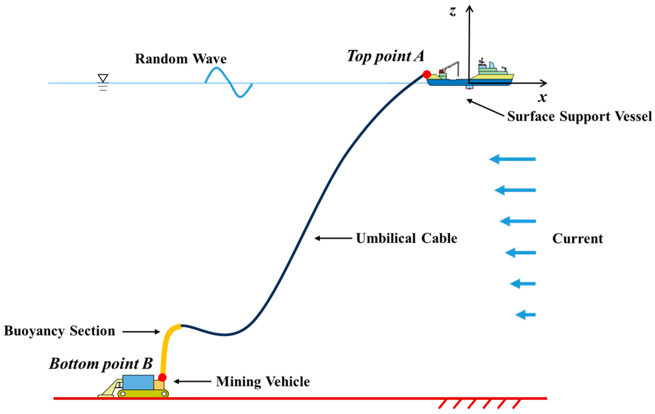
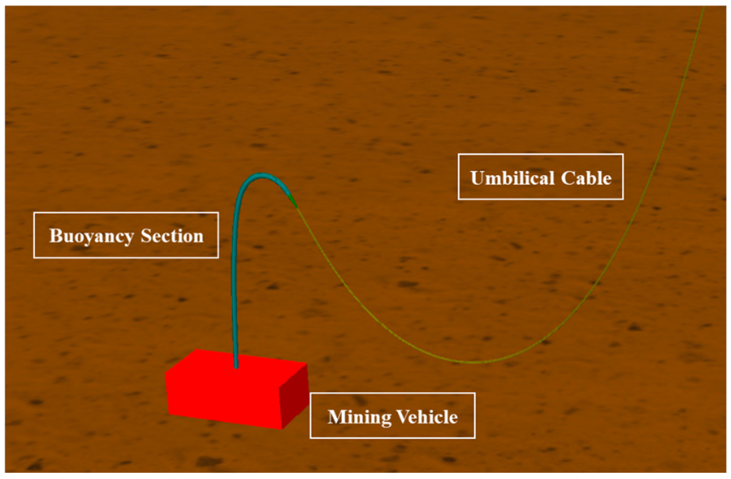
Since the umbilical is rigidly connected to the mining vehicle, excessive angular deflection at the lower end may lead to joint failure or structural damage. Therefore, the configuration design of the umbilical should consider not only the distribution of buoyancy modules but also the bending restriction requirement at the lower termination. To address the aforementioned issues, this study introduces the S-shaped umbilical configuration based on the traditional steep-wave layout, as illustrated in
Figure 1.
The S-shaped configuration mainly consists of a buoyancy section and a hanging section. The buoyancy section is equipped with buoyant bend limiters, which not only provide buoyancy but also effectively restrict excessive bending. This design enables the umbilical to maintain a stable wave-like profile during the movement of the mining vehicle, ensuring effective bend control and configuration stability.
Compared with the double-stepped and steep-wave configurations, the S-shaped configuration exhibits two distinct advantages: (1) it provides superior bending limitation, better accommodating the large-scale horizontal movements of the mining vehicle on the seabed; (2) and it offers enhanced protection for the umbilical cable, reducing the mechanical impact transmitted from the mining vehicle to the bottom end of the umbilical cable. (3) Moreover, this configuration allows the buoyant modules to be integrated during umbilical fabrication, eliminating the need for offshore installation or removal during deployment and recovery. Consequently, the overall efficiency of deployment and retrieval operations is improved, and operational continuity is more effectively maintained.
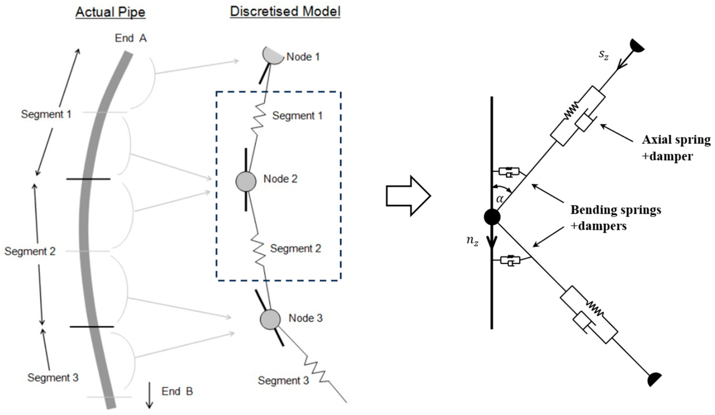
The primary objective of the present manuscript is to introduce the S-shaped configuration, and also, a comparative analysis is conducted against the double-stepped, steep-wave, and S-shaped configurations in terms of static configurations and mechanical characteristics under extreme near-field and far-field operating conditions. Considering hydrodynamic loads such as ocean currents and irregular waves, as well as motion excitations from the surface support vessel, a fully coupled dynamic model of the deep-sea mining umbilical system under operational conditions is developed based on the lumped-mass method. The motion trajectory of the beacon in sea trials is simulated using this model, and the simulated trajectory is compared with the measured one to verify the model’s accuracy and applicability. The spatial configurations and mechanical responses of three umbilical configurations were evaluated, including maximum effective tension, lateral drift amplitude, and the mining vehicle’s overturning moment.
3. In Situ Operational System Model of the Deep-Sea Mining Umbilical System
Figure 3 shows a schematic of the deep-sea mining in situ operational system. The in situ operational system Model of the deep-sea mining umbilical (abbreviated as the in situ operational model) primarily consists of the surface support vessel, the umbilical, and the mining vehicle. During deep-sea mining operations, the umbilical is deployed from an A-frame located at the stern of the surface support vessel and controlled by a winch system as it enters the water. It extends vertically through the water column to the seafloor, where its lower end is connected to the seabed mining vehicle via a cross universal joint. This connection allows the mining vehicle to perform pitch and roll motions over uneven seabed terrain, ensuring smooth load transfer and flexible response of the umbilical throughout the operation.
The origin of the global coordinate system is set at the center of gravity of the surface support vessel, with the X-axis pointing toward the bow, the Y-axis toward the starboard, and the Z-axis vertically upward. An implicit time-domain integration method implemented in OrcaFlex is employed to simulate the dynamic response of the deep-sea mining in situ operational system. The total simulation time is 3 h, corresponding to a representative sea state duration.
Since the time step directly influences both numerical accuracy and computational efficiency in dynamic simulations, a sensitivity analysis was performed to assess the appropriateness of the selected value. Five kinds of time steps (0.1 s, 0.05 s, 0.01 s, 0.005 s, and 0.001 s) were tested, and the corresponding maximum effective tensions and relative errors are summarized in
Table 2. Using 0.001 s as the reference, it can be seen that a time step of 0.1 s results in a relative error exceeding 2%, while the total computation time for 0.001 s is 69 times longer than that for 0.1 s. To balance computational accuracy and efficiency, a time step of 0.01 s is adopted in all subsequent simulations.
3.1. Surface Support Vessel
The surface support vessel used in this study is characterized by a total length of 132.6 m and a beam of 27 m. It is designed with a maximum draft of 7 m and a displacement of approximately 18,467 t. The umbilical is connected to the surface support vessel at the stern, and the vessel’s motion in waves is transmitted to the top end of the umbilical. The vessel is modeled with six degrees of freedom corresponding to wave frequencies. The displacement Response Amplitude Operators (RAOs) of the surface support vessel are applied, as shown in
Figure 4, and the resulting vessel motion is calculated and used as the boundary condition at the top end of the umbilical [
15].
3.2. Umbilical Cable
The umbilical adopts a non-metallic armored structure. In practical engineering, the top end of the umbilical is deployed from the A-frame at the stern of the surface support vessel, while the bottom end is connected to the seabed mining vehicle via a universal joint, allowing rotation in two perpendicular directions. Since both ends can rotate to a certain extent, the connections at both ends are assumed to be hinged. The calculation parameters of the umbilical are shown in
Table 3.
To evaluate the influence of segmentation on numerical accuracy and computational efficiency, the double-stepped umbilical configuration, representing the most structurally complex configuration, was selected for comparison under three discretization schemes. In Case 1, all sections were discretized using a uniform segment length of 0.1 m, resulting in an extremely fine mesh. In Case 2, a uniform segment length of 1 m was applied, producing a much coarser discretization. In Case 3, an adaptive discretization strategy was adopted: finer discretization is applied at both ends of the umbilical, particularly in critical regions such as the buoyancy section, while a coarser discretization is used in the middle section. The specific segmentation adopted in Case 3 is provided in
Table 4.
Table 5 presents the total calculation time, maximum tension, and maximum bending curvature for the three discretization cases, with Case 1 used as the reference to calculate the relative errors of Case 2 and Case 3. The results indicate that the three cases exhibit very small differences in maximum tension and maximum curvature, with the largest relative error not exceeding 0.26%. However, the difference in computational cost is substantial: the total calculation time of Case 1 is 17.46 times that of Case 2 and 9.12 times that of Case 3. Considering both numerical accuracy and computational efficiency, Case 3 is selected as the discretization scheme for the umbilical model.
3.3. Buoyancy Module and Bend Stiffener
The buoyant section adopts a configuration of continuously arranged buoyancy modules.
Figure 5 shows a structural schematic of the buoyancy modules. In practical installation, the gaps between adjacent modules are minimal; therefore, these gaps are neglected in the modeling process. The calculation parameters of the buoyancy module are listed in
Table 6. Considering that the buoyancy modules are clamped tightly onto the umbilical using fixtures, the buoyant section is modeled with the same axial and bending stiffness as the umbilical.
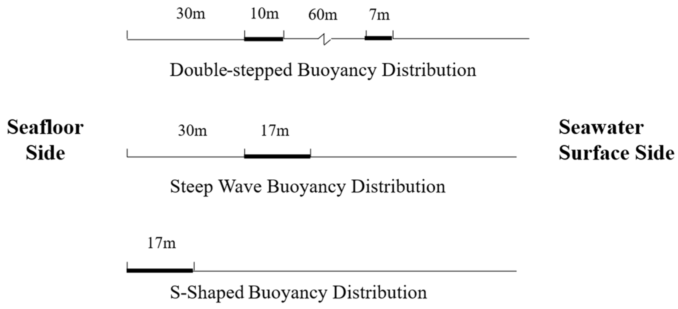
The arrangement and positioning of the buoyancy module for the double-stepped [
25], steep-wave, and S-shaped configurations are shown in
Figure 6. To ensure that all three configurations provide the same total buoyancy, the total length of the buoyancy module is set to 17 m for each configuration.
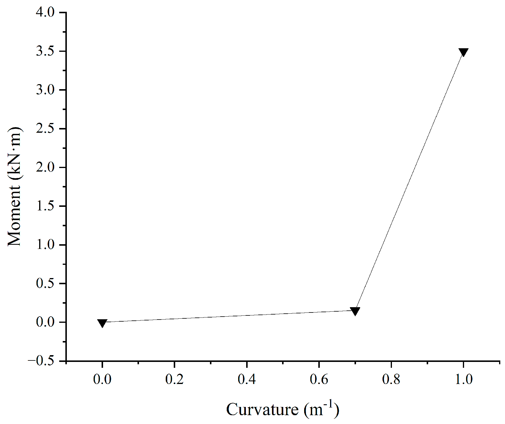
A conical bend stiffener is installed at the top of the buoyant section, with its moment-curvature relationship shown in
Figure 7. When the curvature is less than 0.7 m
−1, the bend stiffener exhibits low bending stiffness; however, once the curvature exceeds 0.7 m
−1, its bending stiffness increases significantly. This design helps prevent excessive bending at the connection between the umbilical and the buoyant section and reduces stress concentration in this region.
3.4. Mining Vehicle
The fundamental specifications of the mining vehicle are presented in
Table 7. This vehicle adopts a tracked propulsion system, providing favorable mobility and operational stability on the seafloor. It has a total mass of 18 tons and dimensions of 8.3 m × 3.86 m × 3 m, with a maximum traveling speed of 1 m/s. The schematic diagram of the mining vehicle is shown in
Figure 8. In addition, the vehicle is equipped with multiple monitoring and control nodes capable of real-time acquisition of key operational parameters such as attitude, traction force, and position. These features ensure the safety and controllability of deep-sea mining operations.
As the mining vehicle is equipped with self-propulsion and can move autonomously, fluid resistance and frictional resistance acting on it are neglected in this study. The mining vehicle is simplified as a rectangular block with equivalent mass. During the simulation of the umbilical’s dynamic response, the mining vehicle is assumed to remain fixed on the seabed, and thus treated as a stationary boundary condition.
3.5. Marine Environment
The operational water depth is set to 1380 m, with the seabed assumed to be a horizontal plane. The current velocity is based on monitored data, and the current profile is shown in
Table 8. The surface current velocity is 1.025 m/s, and below a depth of 1100 m, the current velocity stabilizes at 0.053 m/s. The seawater density is assumed to be 1025 kg/m
3. Currently, deep-sea mining systems are designed to operate under sea states of Grade 5 or below, with safe deployment and recovery limited to sea states of Grade 4 or below [
28]. Therefore, the significant wave height is set to 4.0 m, corresponding to Grade 5 sea conditions. Irregular waves are used to simulate the most severe operational conditions during deep-sea mining, with the wave period set to 4.5 s.
The JONSWAP wave spectrum [
35] is adopted for wave simulation, and the target spectrum is given by the following equation:
where
is the wave frequency;
is the peak frequency. The main wave parameters are shown in
Table 9.
4. Results and Discussions
When the deep-sea mining vehicle is conducting collection operations, the following constraints are placed on the in situ operational model [
17]:
Constraint 1: To prevent the umbilical cable from experiencing axial rupture, the maximum effective tension of the umbilical cable should be less than 470 kN.
Constraint 2: To prevent excessive bending of the umbilical cable, the maximum curvature of the umbilical cable should be less than 0.7/m.
Constraint 3: To prevent the mining vehicle from overturning, the longitudinal overturning moment of the vehicle should be less than 100 kN·m, and the lateral overturning moment should be less than 75 kN·m.
Constraint 4: To prevent the umbilical cable from touching the seabed and being crushed by the mining vehicle, the minimum ground clearance at the trough of the umbilical cable should not be less than 3 m, and leave a certain amount of redundant space at the top of the mining machine.
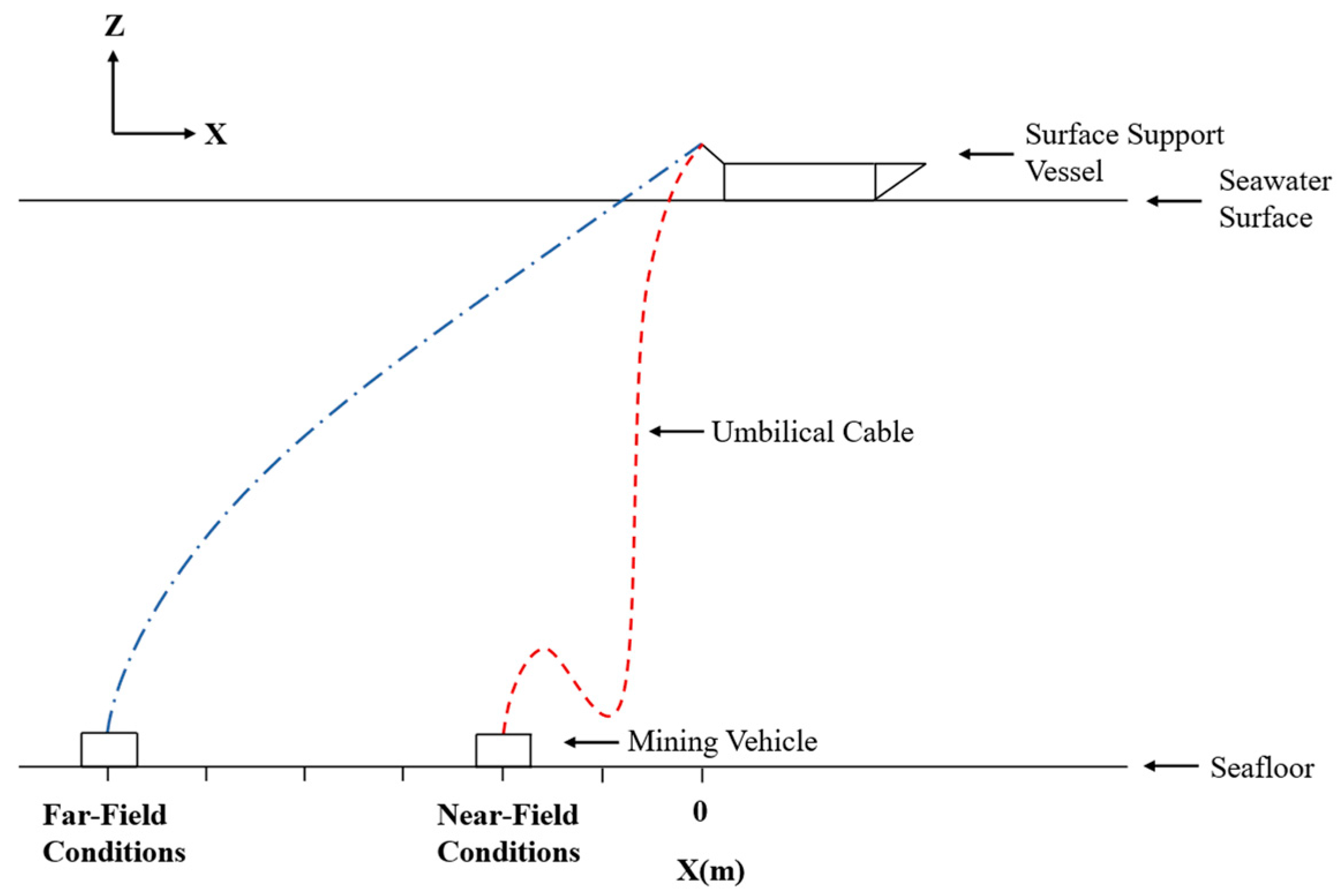
Under the aforementioned operational constraints, the near-field condition is defined as the minimum allowable horizontal distance between the mining vehicle and the support vessel under the operational constraints. If the distance falls below this threshold, Constraints 2 and 4 may not be satisfied, causing the umbilical to become excessively slack. This can result in excessive bending, local compression, or even contact with the seabed, thereby increasing the risk of the cable being damaged or crushed by the mining vehicle. Correspondingly, the far-field condition is defined as the maximum allowable horizontal distance between the mining vehicle and the support vessel. Exceeding this distance may break Constraint 1 and 3, resulting in excessive tension in the umbilical, which in turn poses severe risks such as the potential overturning of the mining vehicle or rupture of the umbilical cable.
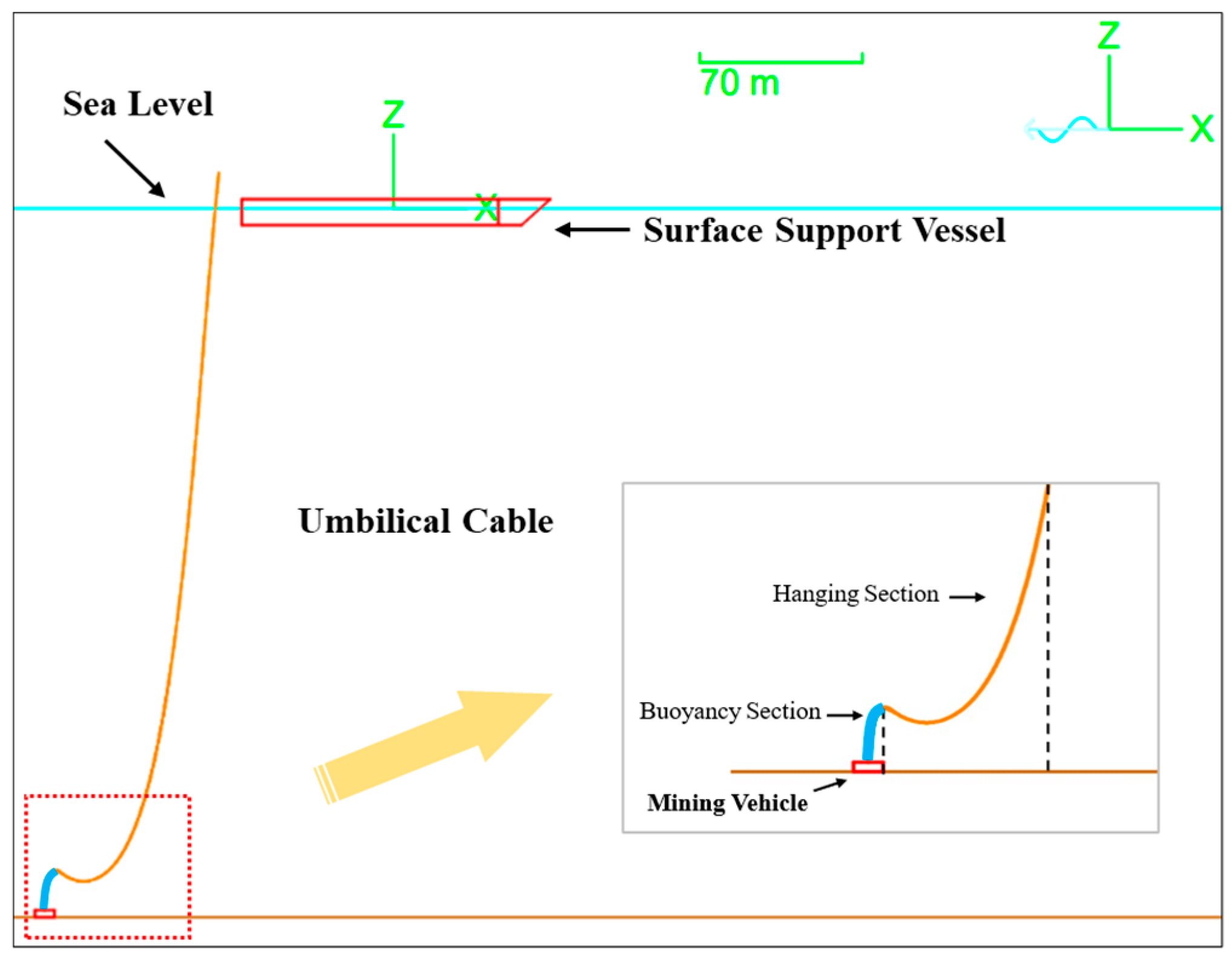
These two conditions represent extreme scenarios that effectively bound the cable’s dynamic behavior under various operating states, as shown in
Figure 9.
4.1. Validation of the Beacon Trajectory
Firstly, in order to verify the accuracy and engineering applicability of the in situ operational model, a set of data from a representative sea trial was selected for comparative analysis. The key equipment parameters used in the sea trial, such as the umbilical, surface support vessel, and seabed mining vehicle, were highly consistent with those in the in situ operational model, providing a solid basis for validation. Detailed parameters are listed in
Table 3 and
Table 6. During the sea trial, the seabed mining vehicle successfully performed walking operations, and a beacon was installed at the top of the buoyancy section, with the primary purpose of capturing its actual displacement trajectory.
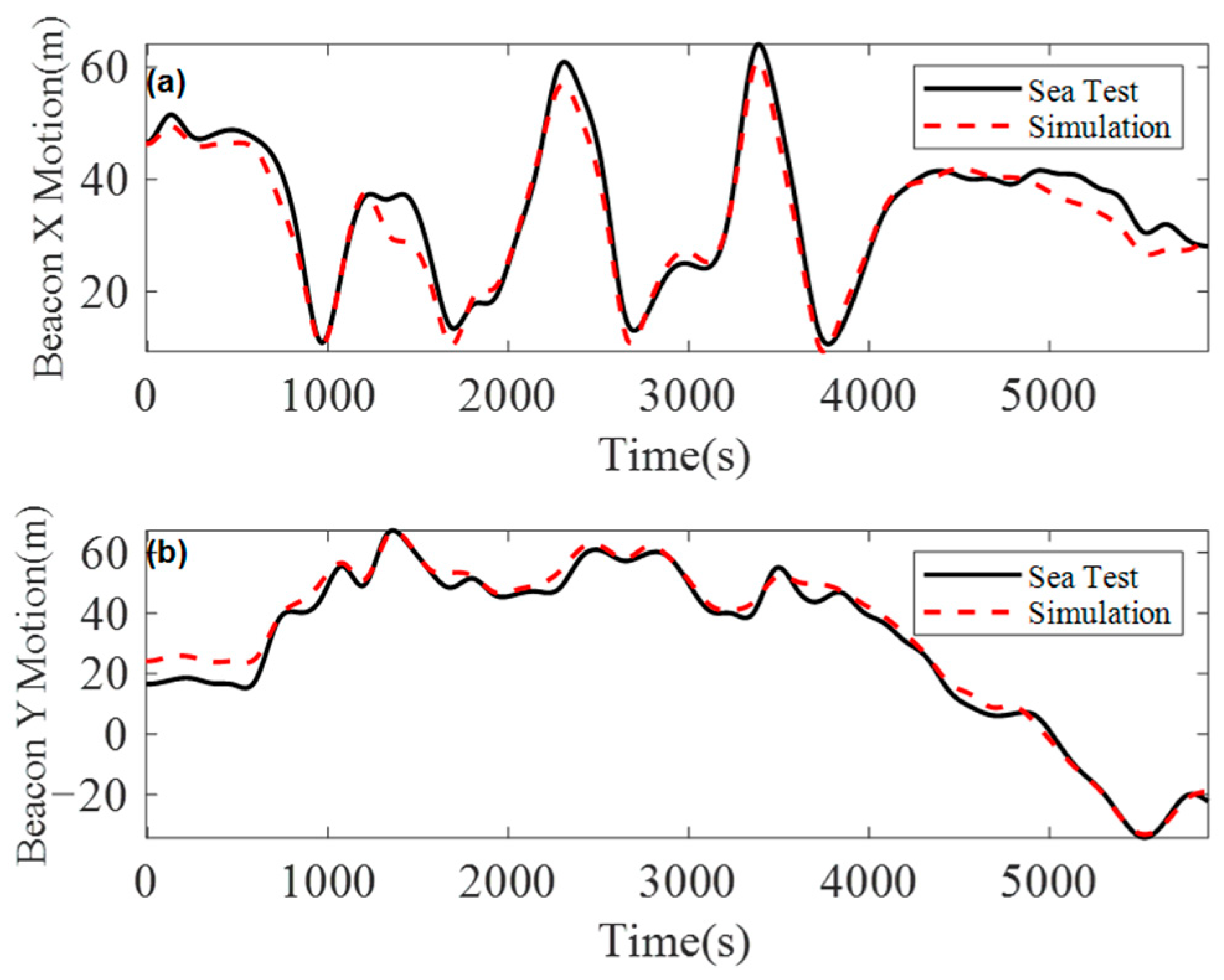
Under this condition, a coupled dynamic model corresponding to the actual sea trial environment at a water depth of 1072 m was established to simulate the dynamic response of the umbilical. From the simulation results, the displacement trajectory at the top of the buoyancy section was extracted and subsequently compared with the measured trajectory obtained from the beacon. The comparison reveals a strong agreement between the simulated and measured motion responses of the beacon, as shown in
Figure 10, confirming the accuracy and reliability of the proposed deep-sea mining umbilical in situ operational model in forecasting dynamic behavior.
4.2. Dynamic Response Analysis of the Umbilical Under Near-Field Conditions
Under a horizontal offset of 225 m between the mining vehicle and the support vessel, and environmental conditions specified in
Section 3.5, the static configurations and mechanical responses of the three configurations under near-field conditions are compared to analyze their mechanical performance in extreme near-field scenarios, emphasizing the influence of the umbilical’s bending deformation on the overall behavior of the in situ operational system.
4.2.1. Static Configuration
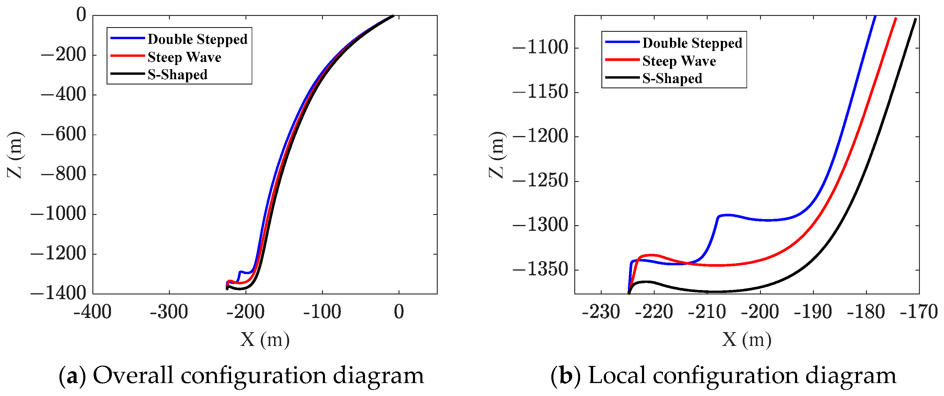
Figure 11a shows the static position diagrams for three configurations, while
Figure 11b presents the local static position diagrams for the three configurations.
Table 10 lists the distance from the wave trough of the umbilical to the seabed, which is also referred to as the minimum ground clearance.
Under near-field conditions, to avoid the umbilical from touching the seabed due to excessive slack, it is necessary to analyze its height above the seabed, ensuring that there is sufficient clearance between the umbilical and the seabed. As can be seen from
Figure 11b and
Table 10, in terms of controlling the clearance height from the seabed of the suspended section, the double-stepped configuration, due to its multiple buoyancy sections, can effectively increase the umbilical cable’s clearance height. In the S-shaped configuration, the buoyancy modules are positioned close to the seabed, causing the lowest point of the hanging section to be closer to the seabed compared with the other two configurations. The minimum static clearance between the suspended umbilical section and the seabed is 5.47 m, which is still 2.47 m higher than the top of the mining vehicle. Compared to the S-shaped configuration, the steep wave configuration improves the position of the buoyancy sections by raising them, resulting in a higher clearance from the seabed.
However, it is evident that all three configurations maintain sufficient clearance above the seabed, satisfying the operational clearance requirements of the mining vehicle.
Ocean currents also play a crucial role in affecting the configuration of the umbilical. As can be seen from
Figure 11a, under the influence of ocean currents, the upper section of the umbilical departs from its naturally hanging profile and experiences significant lateral displacement.
To further analyze the influence of ocean current on the lateral drift of umbilical, this study sets two typical current velocity conditions: Case 1 with no ocean current and Case 2 adopting the velocity profile shown in
Table 8. The lateral displacement characteristics of umbilical configurations under the two conditions are compared, and the results are presented in
Figure 12. It was found that, at a water depth of 800 m, the lateral offset reaches 129.89 m for the double-stepped configuration, 121.70 m for the steep-wave configuration, and 107.12 m for the S-shaped configuration.
Among the three configurations, the S-shaped configuration exhibits the smallest lateral drift under current influence, indicating better stability and structural reliability compared with the double-stepped and steep-wave configurations.
4.2.2. Effective Tension
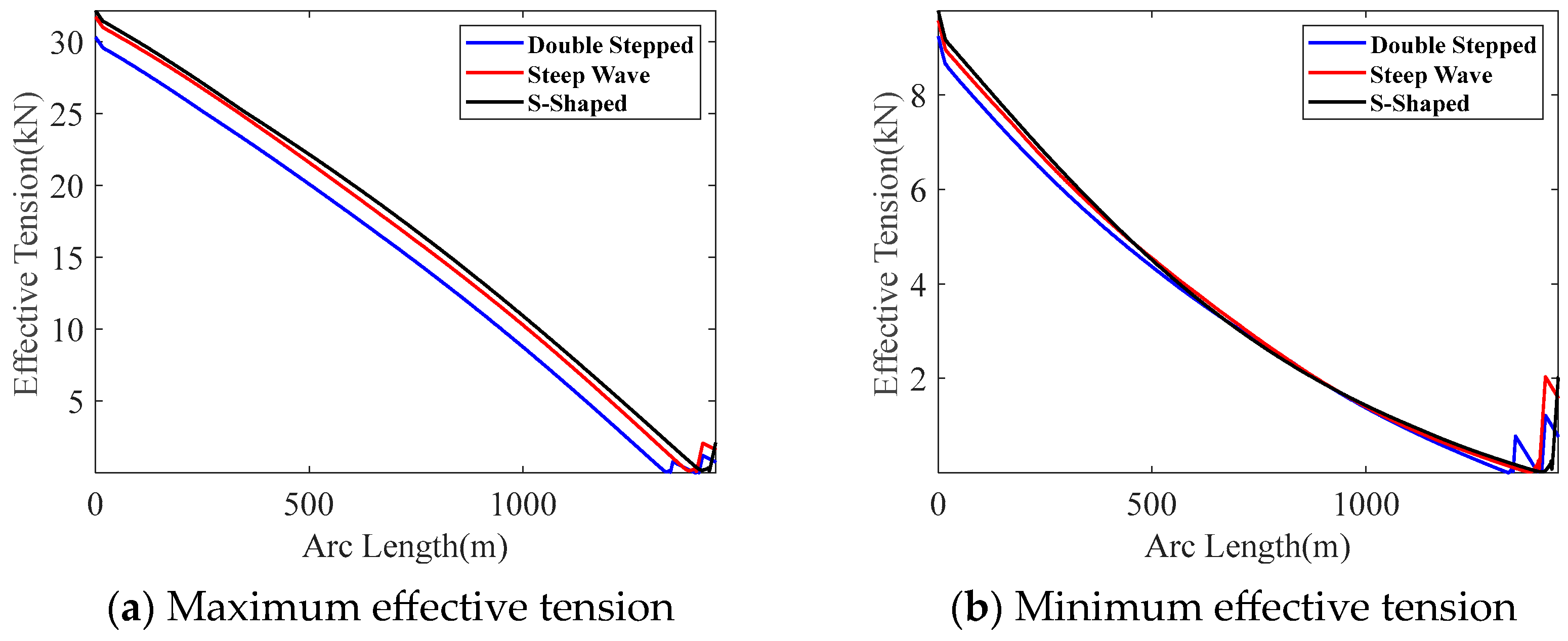
The effective tension can be used to characterize the stretching load borne by the umbilical cable.
Figure 13a shows the maximum effective tension values corresponding to the three configurations.
Figure 13b shows the minimum effective tension values corresponding to the three configurations.
From
Figure 13a, it was found that the maximum tension occurs at the top of the umbilical cable, indicating that this location bears the highest stretching load. Therefore, this position is one of the key critical points of the umbilical cable. From
Figure 13b, it was found that the minimum tension generally occurs at the top of the buoyancy section, and due to the influence of the buoyancy section, the effective tension in this segment gradually increases. This phenomenon is primarily attributed to the additional buoyancy provided by the modules. When the umbilical cable enters the buoyancy section, the buoyancy not only completely offsets its self-weight but also generates an upward axial component, leading to a local increase in effective tension. The magnitude of this increase is related to the total buoyancy of the section. As shown in
Figure 13b, the S-shaped and steep-wave configurations exhibit almost identical tension recovery magnitudes in the buoyancy section, whereas in the double-stepped configuration, the buoyancy section is split into two segments, resulting in two separate recovery processes and corresponding local peaks.
Further analysis of the top and bottom tension of the umbilical cable is conducted.
Table 11 lists the variation ranges of the top and bottom tension for the three configurations. Comparing the maximum top tension values of the three configurations, the order is: Double-Stepped < Steep Wave < S-Shaped. However, the differences in the maximum tension values among the three configurations are relatively small. Among these, the S-shaped configuration has the largest variation in top tension, with a minimum tension of 9.78 kN, a maximum tension of 32.15 kN, and a variation range of 22.37 kN.
4.2.3. Bending Curvature
The bending load borne by the umbilical cable can be represented by the bending curvature.
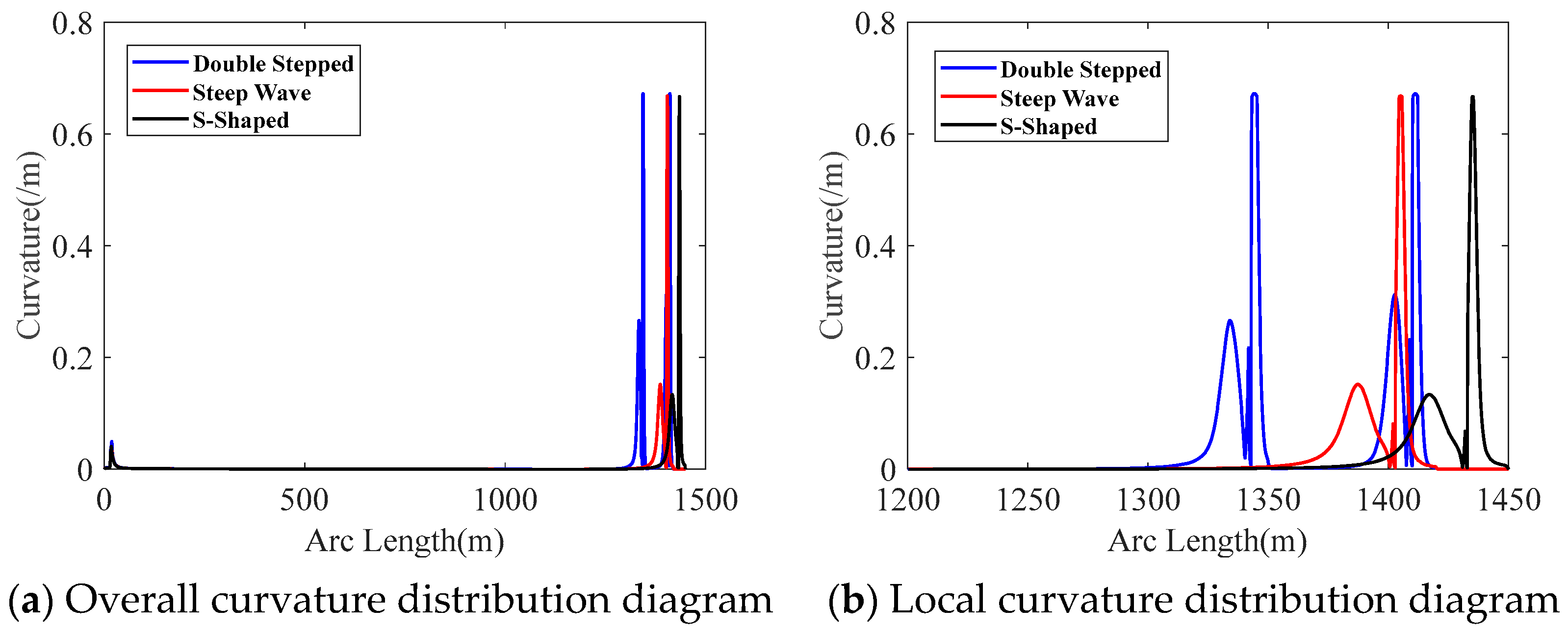
Figure 14 shows the distribution of the bending curvature along the length of the umbilical cable for the three configurations.
From
Figure 14, it can be observed that the maximum bending curvature values are similar for all three configurations, and the location of the maximum curvature occurs at the top of the buoyancy section in each case. Additionally, the curvature values of the umbilical cable are smaller in the middle of the suspended section. This is due to the distance from the top buoyancy and the dynamic disturbances from the marine environment, as well as the hydrodynamic damping effect, which result in a smaller bending amplitude of the umbilical cable. Due to the presence of two buoyancy sections in the double-stepped configuration,
Figure 14 shows two peaks in the curvature. The first peak is 0.6722 m
−1, and the second peak is 0.6706 m
−1. Therefore, compared to the steep-wave and S-shaped configurations, which only have a single buoyancy section, the double-stepped configuration is more prone to bending fatigue and fatigue fracture.
Table 12 presents the maximum curvature values of the umbilical cable and their distances from the top of the umbilical cable for the three configurations. Comparing the maximum curvature values of the three configurations, the order is as follows: double-stepped > steep wave > S-shaped. However, the differences in the maximum bending curvature values among the three configurations are relatively small. In addition, due to the different installation positions of the buoyancy sections, the maximum bending curvature values are not significantly affected. However, the location where the maximum bending curvature occurs is closely related to the installation position of the buoyancy sections. From
Table 12, we can observe that as the installation position of the buoyancy sections moves closer to the seabed, the location of the maximum bending curvature also gradually shifts closer to the seabed.
4.2.4. Overturning Moment
The lateral and longitudinal overturning moments of the mining vehicle can be used to estimate the risk of the mining vehicle overturning. By comparing the lateral and longitudinal overturning moments of the mining vehicle, the adaptability of the three configurations to the mining vehicle’s movement can be characterized. The smaller the overturning moment value, the lower the risk of the mining vehicle overturning.
Table 13 lists the maximum lateral and longitudinal overturning moments of the mining vehicle for the three configurations. Under near-field conditions, the overturning moments of the mining vehicle for all three configurations are at a relatively low level. This is because, in this condition, the umbilical cable near the mining vehicle is relatively relaxed and can maintain a good vertical shape. At this point, the effective tension at the connection between the umbilical cable and the mining vehicle is smaller. At the same time, this also indicates that the umbilical cable has a minimal impact on the mining vehicle’s movement operations, which helps ensure the stability of deep-sea mining operations.
In conclusion,
Section 4.2 analyzes the behavior of the umbilical cable configurations under near-field conditions. The results show that all three configurations approach their curvature and ground clearance limits. This is due to the accumulation of the umbilical cable above the buoyancy section when the mining vehicle is positioned closer to the surface support vessel, leading to increased bending in this region and a gradual approach to the seabed. As a result, curvature and ground clearance become the critical factors in determining the performance of the umbilical cable under near-field conditions.
Furthermore, among the three configurations, the double-stepped configuration performs better in terms of ground clearance, top-end tension, and the mining vehicle’s overturning moment. However, due to its two buoyancy sections, this configuration faces a higher risk of fatigue damage from bending fatigue compared to the other two configurations. In contrast, the S-shaped configuration demonstrates superior performance in terms of lateral drift and bending behavior under the influence of ocean currents, outperforming the other configurations in these aspects.
4.3. Dynamic Response Analysis of the Umbilical Under Far-Field Conditions
Under a horizontal offset of 365 m between the mining vehicle and the support vessel, and the environmental conditions specified in
Section 3.5, the static configurations and mechanical responses of the three configurations under far-field conditions are compared to evaluate their mechanical performance in extreme far-field scenarios, with particular emphasis on the influence of the umbilical’s tensioned state on the overall behavior of the in situ operational system.
4.3.1. Static Configuration
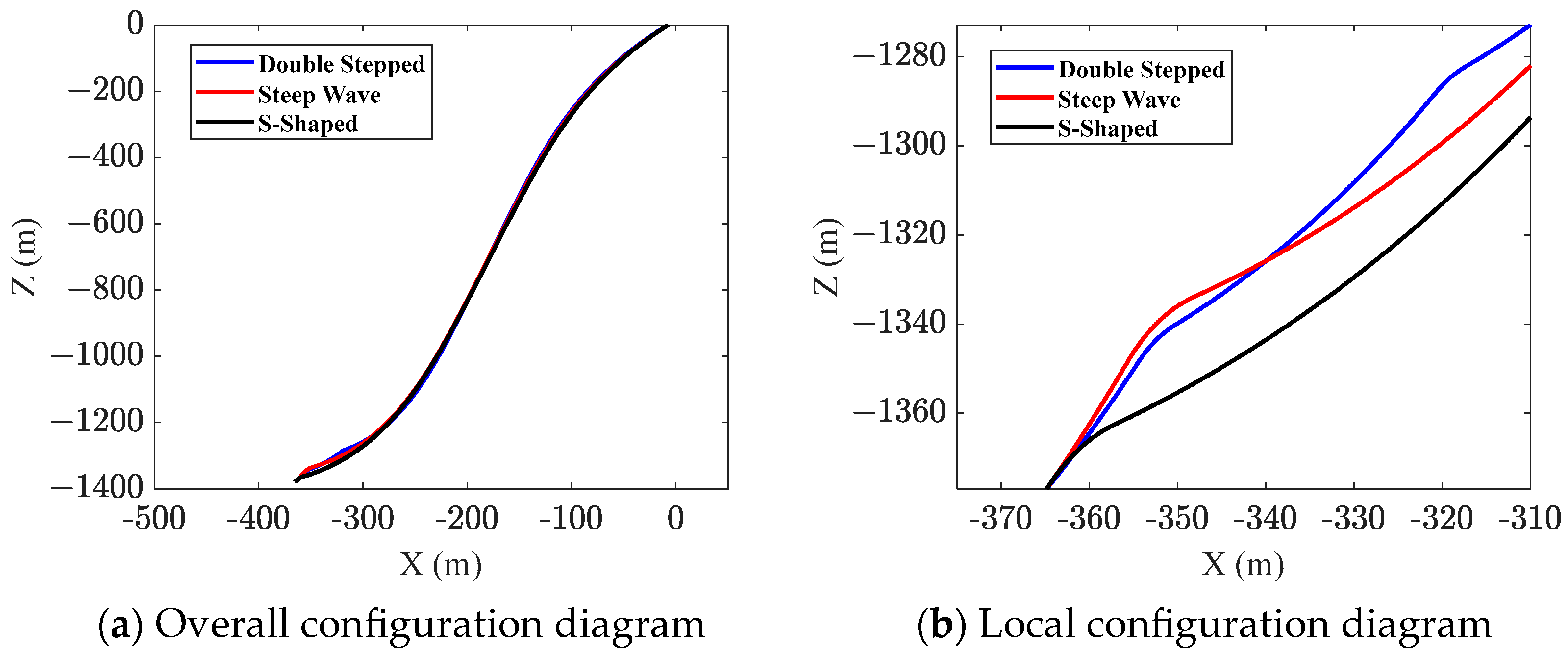
Figure 15a shows the static position diagrams for the three configurations, while
Figure 15b presents the local static position diagrams for the three configurations.
From
Figure 15a, it can be observed that under the far-field condition, the umbilical cable remains in a tensioned state due to the large distance between the support vessel and the mining vehicle. As a result, none of the three configurations can maintain their characteristic wave-like profiles as exhibited in the near-field condition, and the overall geometry appears significantly elongated and nearly straightened.
Although the deep-sea mining system satisfies Constraints 1~4 under this far-field condition, certain new phenomena may still arise. For instance, when dynamic disturbances generated by the surface support vessel and wave motion are transmitted downward along the umbilical cable, localized compression may occur near the buoyancy section. A detailed analysis of this phenomenon is presented in
Section 4.3.2.
4.3.2. Compression
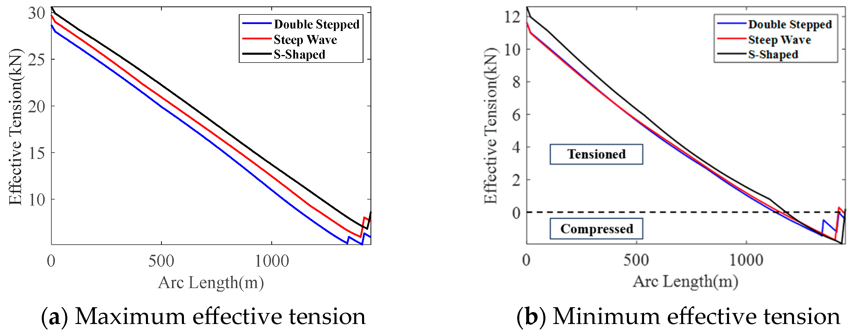
Figure 16a shows the maximum effective tension values corresponding to the three configurations, while
Figure 16b shows the minimum effective tension values for the three configurations.
As shown in
Figure 16b, a localized compression region is observed on the umbilical cable near the seabed, and
Table 14 lists the maximum compression values of the umbilical cable and their distances from the top of the umbilical cable for the three configurations.
As shown in
Table 14, the maximum compression points for all three configurations occur at the top of the buoyancy section. Additionally, the compression levels of all three configurations are minor and remain within the permissible limit of the umbilical cable’s structural capacity. Among them, the S-shaped configuration experiences slightly higher compression with an extreme value of 1.94 kN, while the double-stepped configuration experiences slightly lower compression. It was found that the top of the buoyancy section is one of the key stress points of the umbilical cable. Not only can excessive bending occur at this point, but compression-induced buckling may also take place.
As shown in
Figure 17, the effective tension at the top of the buoyancy section fluctuates around a positive mean value for all three umbilical configurations, indicating that the cables remain predominantly in a tensioned state. Nevertheless, transient compressive phases are also observed, as evidenced by the negative values of effective tension. These results suggest that although the umbilical cables are generally tension-dominant under dynamic excitation, local compression can still occur intermittently at the top of the buoyancy section due to the combined effects of vessel motion and wave-induced tension variations.
In engineering practice, to ensure that the umbilical remains in tension or experiences only negligible compression [
30], this can be achieved by adjusting the horizontal distance between the mining vehicle and the surface support vessel, thereby forming a wave-like configuration that effectively prevents compression of the umbilical cable.
4.3.3. Bending Curvature
The bending load borne by the umbilical cable can be represented by the bending curvature.
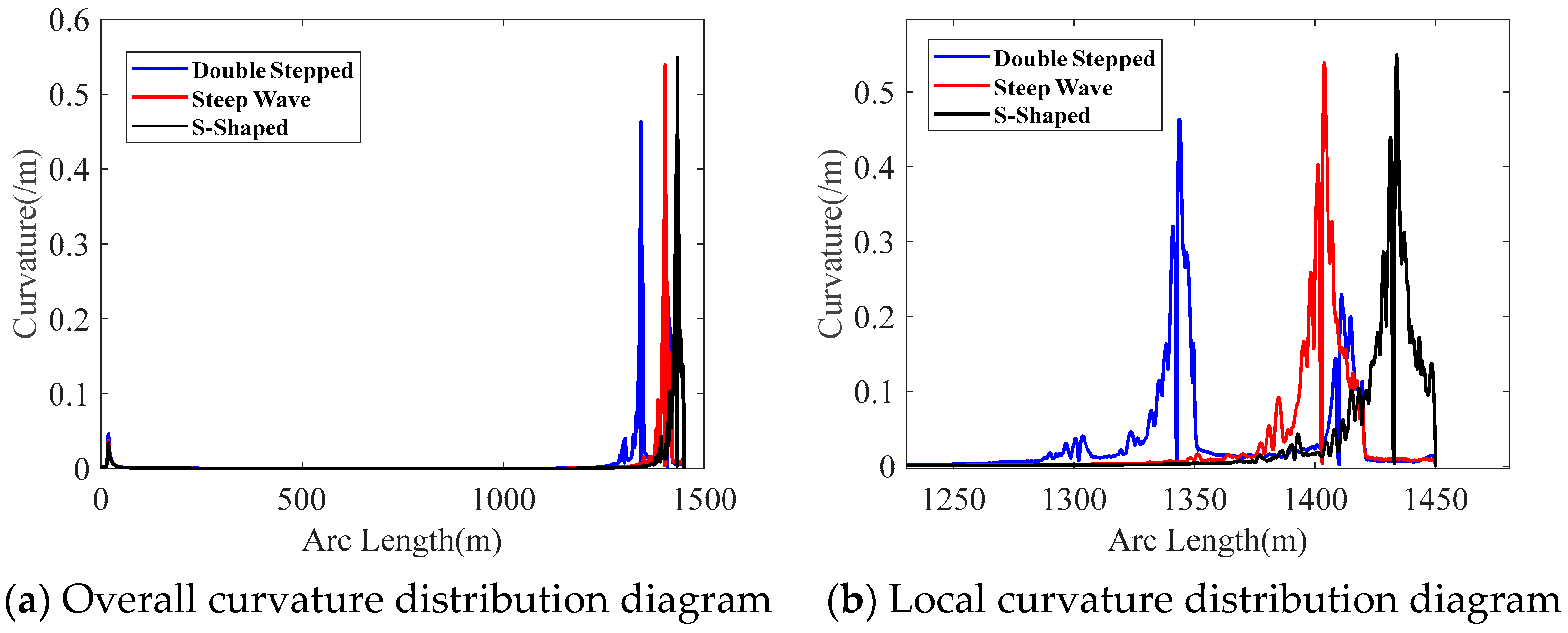
Figure 18 shows the distribution of the bending curvature along the length of the umbilical cable for the three configurations.
From
Figure 18, it was found that there are noticeable differences in the curvature extremes of the three configurations. Among them, the double-stepped configuration performs better, with a curvature extreme of 0.4636 m
−1, while the S-shaped configuration has a curvature extreme of 0.5495 m
−1. Additionally, for the double-stepped configuration, the curvature peaks at both ends of the buoyancy section are no longer close. The first segment has a curvature peak of 0.4636 m
−1, while the second segment has a curvature peak of 0.2289 m
−1. Compared to near-field conditions, the curvature of the three configurations is generally smaller under far-field conditions. This is because, under far-field conditions, the umbilical cable is in a tensioned state, which reduces the bending amplitude. At the same time, smaller and higher-frequency bending is more likely to occur. The significant high-frequency components near the buoyancy section, as seen in
Figure 18, further confirm this phenomenon.
4.3.4. Overturning Moment
Table 15 lists the maximum lateral and longitudinal overturning moments of the mining vehicle for the three configurations.
As seen from
Table 15, under far-field conditions, the bottom of the umbilical cable is in a tensioned state. Compared to the relaxed state under near-field conditions, the mining vehicle’s overturning moment significantly increases. When the umbilical cable is in a tensioned state, as the horizontal distance between the mining vehicle and the surface support vessel increases, the rate of change in the longitudinal overturning moment will increase rapidly.
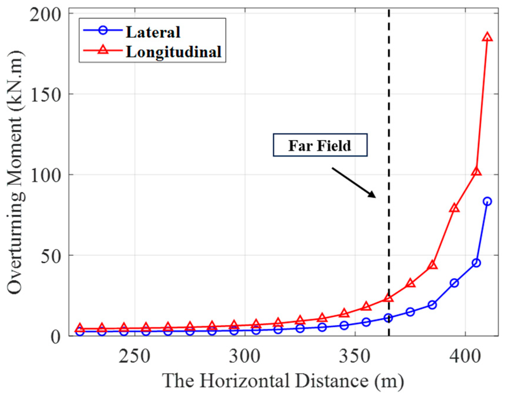
Taking the S-shaped configuration as an example,
Figure 19 illustrates the variation curves of the overturning moment of the mining vehicle with the horizontal distance between the mining vehicle and the surface support vessel. It can be seen from the figure that when the horizontal distance between the mining vehicle and the surface support vessel is between the near-field condition and the far-field condition, the overturning moment of the mining vehicle is generally at a low level, and the operation stability is good.
However, when the horizontal distance between the ship and the vehicle exceeds the far-field condition, the overturning moment of the mining vehicle shows an exponential growth trend, and the growth rate of the longitudinal overturning moment is significantly faster than that of the lateral overturning moment, at which time the operation stability of the mining vehicle drops sharply. In addition, when the horizontal distance is further increased by 40 m, the overturning moment sharply rises to 101.51 kN·m, exceeding the mining vehicle’s critical overturning threshold of 100 kN·m, and the mining vehicle will undergo longitudinal rollover, which will seriously affect the safety of the deep-sea mining system operation.
In conclusion,
Section 4.3 analyzed the static configuration, mechanical response, and synergistic interaction between the mining vehicle and the umbilical cable under far-field conditions. The results show that under these conditions, the lower end of the umbilical cable experiences significant deflection and remains tensioned, leading to localized compression and high-frequency curvature variations. Additionally, the mining vehicle’s overturning moment is significantly higher than under near-field conditions, with an accelerated rate of change as the horizontal distance between the mining vehicle and the surface support vessel increases. Once the distance exceeds the far-field threshold, the overturning moment grows exponentially. Furthermore, the analysis of different umbilical configurations reveals that the double-stepped configuration performs better overall, with lower curvature extremes, while the S-shaped configuration shows higher curvature and more pronounced local compression.
Specifically, the analysis in
Section 4.3 highlights that under far-field conditions, the deflection of the umbilical cable near the seabed significantly impacts the deflection angle at the cable’s end and the mining vehicle’s overturning moment. These factors emerge as critical determinants of the operational safety of deep-sea mining systems under far-field conditions. Consequently, in engineering practice, it is crucial to prioritize the analysis of these two factors to ensure the stability and safety of operations.
