Article

Trajectory Tracking Control of an Autonomous Underwater Vehicle Under Disturbance and Model Uncertainty

1
Subsea Engineering Department, China Offshore Fugro Geosolutions (Shenzhen) Co., Ltd., Shenzhen 518054, China
2
School of Robotics and Advanced Manufacture, Harbin Institute of Technology, Shenzhen 518055, China
*
Author to whom correspondence should be addressed.
These authors contributed equally to this work.
J. Mar. Sci. Eng. 2025, 13(11), 2210; https://doi.org/10.3390/jmse13112210
Submission received: 24 October 2025 / Revised: 14 November 2025 / Accepted: 18 November 2025 / Published: 20 November 2025
(This article belongs to the Special Issue Advanced Studies in Marine Mechanical and Naval Engineering)

Abstract

This paper studies the trajectory tracking control problem of an autonomous underwater vehicle (AUV). A robust model predictive control (MPC) framework based on the implementation of the receding horizon is implemented to address the challenges of unknown external disturbances and model uncertainties faced by the AUV in trajectory tracking control. Within this MPC framework, a formulation that simultaneously handles both practical actuator limitations and dynamic environmental constraints is introduced. Specifically, the controller enforces hard constraints on both the maximum driving force and also the maximum rate of change in the propeller driving force. This rate constraint is essential for ensuring the control signal respects the physical dynamics of the thrusters and prevents hardware damage. These hardware-level constraints are integrated with online updates of system state constraints which define the AUV’s working space, granting it autonomous obstacle avoidance capabilities. Finally, the performance of the controller is demonstrated by simulations and physical experiment results.

1. Introduction

The core feature of autonomous underwater vehicles (AUVs) is the ability to make appropriate response without operator intervention during the mission, and the ability to track accurately is its technical basis. However, AUVs usually have characteristics such as underactuation and non-integrable acceleration, and their kinematic and dynamic models are highly nonlinear and coupled. Complex underwater environments also introduce a large number of perturbations and uncertainties in the motion of AUVs, so the track tracking problem of AUVs has unique difficulties.
At present, the research of under-actuated AUV track tracking control is mainly divided into three kinds of target tracking control problems, such as track point tracking, path tracking and trajectory tracking. Trajectory tracking requires that the control law can guide and track a reference trajectory with time-varying characteristics, so compared with track point tracking and path tracking control, trajectory tracking control is more difficult to realize [1]. In the early research on the trajectory tracking control of underwater vehicles, the design and implementation of simple PID control has been widely used due to the limitation of model accuracy and control hardware. However, PID controller can not provide accurate tracking for second-order and higher objects, nor can it provide dynamic compensation for external interference and model uncertainty. For this reason, many advanced trajectory tracking control methods are proposed. Lei et al. [2] designed a high-gain extended state observer to suppress the internal and external interference of the AUV, and reduced the order of the extended state system, and finally designed the controller based on the backstep method and the combined system method. In this paper, a two-layer framework is proposed, which uses 3D guidance law to deal with the stability of trajectory tracking and robust heuristic fuzzy algorithm to deal with the nonlinearity and uncertainty of the system, and realizes the control of complex and imprecise modeling systems. Thanh et al. [3] constructed four nonlinear interference observers to deal with errors in linearization and uncertainties in 6-DOF AUV models. A control scheme based on cascade structure is proposed, which divides the control problem into two coupling problems of motion control and dynamic control, and realizes the robust tracking of the trajectory of the underdriven AUV. Shen et al. [4] presents a model predictive control framework based on Lyapunov. At each sampling moment, the current control action is obtained by solving a finite time-domain open-loop optimal control problem based on the current system state and control input sequence. In this framework, practical constraints such as propeller saturation can be considered simultaneously, and sub-problems such as inference allocation can be solved simultaneously. Compared with the general backstep control, the control effect is significantly improved. Shojaei et al. [5] took the coordinates of the virtual reference points as the output equation, realized the linearization of input and output feedback, introduced neural network and adaptive technology to compensate the disturbance caused by unknown parameters, waves and ocean currents, and finally realized the tracking control of the three-dimensional space motion of the 5-DOF under-driven AUV, and proved the stability of the internal dynamics of the system. Abdelaal et al. [6] took the position state of obstacles as a time-varying nonlinear constraint, and used a nonlinear disturbance observer to estimate the sea disturbance, and finally realized a nonlinear model prediction controller, which realized the robust automatic obstacle avoidance motion control of ships on the sea surface for static obstacles and moving obstacles. Raffo et al. [7] combined a model predictive controller and a nonlinear H controller to realize three-dimensional trajectory tracking control under hydrodynamic perturbations and parameter uncertainties. Wu et al. [8] realized trajectory tracking control of underactuated surface vehicle under model uncertainty and external disturbance by using a non-singular terminal sliding mode control scheme based on adaptive neural network and nonlinear extended state observer. Li et al. [9] first proposed an interference observer to realize the attenuation of the disturbance influence in a specified time, then constructed an auxiliary dynamic system with time-varying gain to deal with the input saturation phenomenon, and finally realized a robust tracking control scheme that satisfies both the specified time convergence and the transient performance constraints. Duan et al. [10] proposed a reinforcement learning (RL) algorithm that does not require knowledge of the dynamics of the Autonomous Underwater Vehicle (AUV). By online learning of the Hamilton–Jacobi–Isaacs (HJI) equation to compute the optimal solution, they achieved a model-free tracking control strategy for AUVs in the presence of unknown disturbances. Bingul et al. [11] combined an intelligent Proportional-Integral-Derivative (i-PID) controller with a Proportional-Derivative (PD) feedforward controller, proposing a novel control architecture based on Model-Free Control (MFC) principles. This approach maintains trajectory tracking accuracy while achieving effective disturbance rejection and compensation for initial tracking errors. Yao et al. [12] designed a timed sliding mode controller based on the concept of timed sliding manifolds and conducted rigorous theoretical analysis of the global timed stability for the entire closed-loop system. The proposed timed sliding mode control scheme ensures that both position and velocity tracking errors converge to zero within a fixed time, demonstrating strong robustness against lumped uncertainties. Wang et al. [13] based on the homogeneous Lyapunov method, utilized a novel Extended State Observer (ESO) to estimate the unknown states of the system, including unmeasured velocities and lumped disturbances, within a fixed time. They proposed an output-constrained power integrator method to strictly control the ship’s position and heading within predefined output constraints. This approach addresses the timed trajectory tracking control problem for autonomous surface vehicles under the condition of unmeasured speed. Fan et al. [14] integrated a Timed Extended State Observer (FESO) to estimate the unmeasurable velocity and lumped disturbances, and proposed a novel guidance law. This guidance law converges within a fixed time, thereby shortening the convergence time of errors, and achieves trajectory tracking control for Unmanned Surface Vehicles (USVs) under conditions of unmeasurable velocity and unknown disturbances. Batkovic et al. [15] designed a framework for model predictive control (MPC) of flexible trajectory tracking that reduces the requirements for trajectory tracking. This approach addresses the impact of infeasible reference trajectories and prior unknown constraints on the trajectory tracking control task. The method likely involves the use of an MPC algorithm that can handle uncertainties and constraints, allowing for more robust and flexible trajectory tracking in the presence of dynamic variations and system limitations. Chen et al. [16] proposed a Fixed-Time Fractional-Order Sliding Mode Control (FTFOSMC) strategy, combined with Radial Basis Function (RBF) networks, which can effectively evaluate external disturbances and modeling errors, and improve the system’s convergence speed. Bao et al. [17] addressed the issue of the Model Predictive Control (MPC) framework not being able to generate globally optimal solutions by proposing an MPC method based on a combination of Genetic Algorithm with Normal Distribution Partitioning (GA-ACO) and Ant Colony Optimization (ACO). This method, when combined with Dynamic Sliding Mode Control (SMC), can effectively achieve dynamic trajectory tracking control for Autonomous Underwater Vehicles (AUVs). Li et al. [18] in response to the trajectory tracking control problem of dynamically positioned vessels with speed constraints and thruster faults, constructed a fault-tolerant trajectory tracking controller that integrates neural networks and adaptive techniques. This controller not only estimates thruster faults but also demonstrates better robustness against model uncertainties and external disturbances. Wu et al. [19] considered factors affecting Autonomous Underwater Helicopters (AUH) such as current disturbances, modeling uncertainties, and thruster faults. They studied a trajectory tracking controller for AUH based on the prescribed performance method. The feasibility and effectiveness of the algorithm were verified through simulations with two different thruster fault scenarios. Zhou et al. [20] addressing the widespread phenomenon of state quantization in Autonomous Underwater Vehicles (AUV) platforms, proposed a new Quantized Extended State Observer (QESO) and subsequently an adaptive anti-interference control scheme. This scheme can achieve trajectory tracking control without the use of any continuous states.
Since the trajectory tracking task requires both spatial and temporal control of AUVs, many advanced control methods have been widely used, such as the linear optimal control method based on linear quadratic regulator (LQR), nonlinear time-invariant control methods such as sliding mode control and inversion control, and intelligent control methods such as adaptive control method, fuzzy control and neural network. However, the application of many of the above control methods in the underwater environment will encounter some problems. For example, the inversion control needs to obtain accurate model parameters first, which is very difficult for underwater vehicles. Adaptive control can compensate for model uncertainty, but it is too sensitive to unknown parameters. Neural networks and fuzzy systems have good approximations to model uncertainty, but reduce the robustness to modeling errors. At the same time, the above control methods sometimes cannot take into account the input constraints of the underwater vehicle (the force or moment that the thruster can provide) and the state constraints. In this context, model predictive control (MPC) becomes a suitable control method for complex underwater missions because of its ability to efficiently handle input and state constraints while dealing with parametric uncertainties through its robustness.
Recent literature highlights that MPC for AUVs remains a highly active field of research. He et al. [21] systematically summarized the latest progress in path following, trajectory tracking, and formation control, emphasizing the shift towards intelligent and hybrid strategies to manage system nonlinearities, model uncertainties, and physical constraints. Current research is actively exploring the fusion of different control techniques to overcome these challenges. For instance, in the domain of MPC, Liu et al. [22] proposed a Gaussian-Process-based MPC (GP-MPC) that leverages Gaussian process regression to effectively model system uncertainties, thereby enhancing robustness in trajectory tracking and obstacle avoidance. Concurrently, Li et al. [23] developed a cascaded FMPC-FTTSMC framework, where a Fuzzy MPC (FMPC) acts as a kinematic controller, utilizing a fuzzy allocator to adaptively adjust optimization weights for different mission phases (e.g., dive, search, operation), while a Finite-Time Terminal Sliding Mode Control (FTTSMC) serves as the dynamic controller for rapid disturbance rejection. These advancements confirm that MPC and its hybrid formulations are a state-of-the-art approach for the complex AUV control problem.
Aiming at AUV thruster constraint, system state constraint and unknown ocean wave and current disturbance in underwater environment, a robust model prediction controller is designed in this paper, which can achieve robust trajectory tracking control effect and avoid small obstacles.
It is important to differentiate this approach from other advanced control strategies, such as the adaptive sliding-mode control (SMC) methods proposed by Li et al. [24], and formal robust MPC formulations (e.g., min-max, tube-based, or LMI-based MPC). While formal robust MPC techniques can provide rigorous mathematical guarantees of stability and performance bounds, they often come with a significant, and in many cases prohibitive, computational burden. This makes their real-time application challenging for nonlinear systems with the long prediction horizons required for trajectory tracking.The methodology in this paper, therefore, focuses on a computationally tractable MPC framework designed for practical implementation. The robustness of our controller is not proven through formal mathematical guarantees, but rather it is empirically demonstrated through extensive validation against significant model uncertainties (up to ±35%), persistent external disturbances, and online constraint-based obstacle avoidance. The novelty is thus centered on the practical integration of specific, hardware-level constraints (thruster force and rate-of-change limits), which are critical for real-world hardware integrity but are often simplified in more theoretical robust control formulations.
The main contributions of this paper are as follows:
  • A robust Model Predictive Control framework is designed for AUV trajectory tracking, which explicitly handles actuator saturation by constraining the maximum propeller driving force.
  • Thruster rate-of-change constraints are novelly included within the same MPC formulation. This inclusion is critical for ensuring the control signals are physically achievable by the thrusters, preventing control chattering, and protecting hardware integrity.
  • A set of practical hardware-level constraints (both force magnitude and rate-of-change) is holistically integrated with online-updated system state constraints to achieve robust autonomous obstacle avoidance.
The remaining sections of this paper are arranged as follows: Section 2 establishes the kinematic and dynamic models for the AUV, laying the mathematical foundation for the study of AUV motion control; Section 3 designs the MPC trajectory tracking controller, including the design of the cost function and constraints; Section 4 verifies the control performance of the controller through several sets of numerical simulations and physical experiments; and Section 5 concludes the work and brings up recommendation for further research.

2. Modeling of the AUV

The prototype of the AUV studied in this paper has a propulsion configuration as shown in the figure. A set of thrusters located in the center can control the vertical and roll motion of the AUV. The two sets of thrusters symmetrically arranged at the stern and bow are used to control the AUV’s transverse velocity, longitudinal velocity, and heading angle. The spatial motion coordinate system of the AUV is depicted in Figure 1.
For an AUV tasked with inspection of underwater pipelines, it is reasonable to consider its vertical motion to be slow and infrequent. By disregarding the effects of roll and pitch motions, as well as higher-order nonlinear hydrodynamic damping terms, a 3-degree-of-freedom (3-DOF) kinematic and dynamic model for the AUV within the horizontal plane can be constructed as follows:
x ˙ = u c o s Ψ v s i n Ψ y ˙ = u s i n Ψ + v c o s Ψ Ψ ˙ = r m 11 u ˙ = X u u + X u u | u | u + m 22 u r + f u m 22 v ˙ = Y v v + Y v v | v | v m 11 v r + f v I z r ˙ = N r r + N r r | r | r + m 11 u v m 22 u v + M r f u
In the equations, x, y, and Ψ represent the position and heading angle of the AUV in the global coordinate system, respectively. u and v represent the linear velocities of the AUV along the O B X B -axis and O B Y B -axis, respectively. While r represents the angular velocity around the O B Z B -axis. m 11 , m 22 , and I z are the inertial masses of the AUV, including the added mass. X u , X u u , and Y v et al. are the hydrodynamic parameters.
The four thrusters at the stern and bow of the AUV are angled at 45° to the axis, and their thrust force relationship with the driving force can be represented as follows.
f u f v M r = 1 2 1 2 1 2 1 2 1 2 1 2 1 2 1 2 l l l l F 1 F 2 F 3 F 4
Over a certain period of time, assuming that the disturbances caused by waves and currents in the horizontal plane are fixed in the world reference frame and consist of three components in the surge, sway, and yaw directions, the state-space model of the AUV can be written as:
x ˙ = A c x + B c u + g b w b
where x = [ x , y , Ψ , u , v , r ] T is the state vector, u = [ F 1 , F 2 , F 3 , F 4 ] T is the system’s input vector, and w b = [ w u , w v , w r ] T represents the external disturbances acting in three directions in the body-fixed coordinate system, and the matrix within it can be represented as:
A c = 0 0 0 c o s Ψ s i n Ψ 0 0 0 0 s i n Ψ c o s Ψ 0 0 0 0 0 0 1 0 0 0 X u + X u u | u | m 11 m 22 r m 11 0 0 0 0 m 11 r m 22 Y v + Y v v | v | m 22 0 0 0 0 ( m 11 m 22 ) v I z 0 N r + N r r | r | I z
B c = 0 0 0 0 0 0 0 0 0 0 0 0 1 2 m 11 1 2 m 11 1 2 m 11 1 2 m 11 1 2 m 22 1 2 m 22 1 2 m 22 1 2 m 22 l I z l I z l I z l I z
g c = 0 0 0 0 0 0 0 0 0 1 m 11 0 0 0 1 m 22 0 0 0 l I z
The model mentioned above is discretized using the fourth-order Runge–Kutta method. To facilitate the controller’s monitoring and constraining of the control input signals, and to achieve better control effects by embedding an integrator, the state-space equations are rewritten in incremental form.
x ( k + 1 ) u ( k + 1 ) = A c B c 0 4 × 6 I 4 × 4 A x ( k ) u ( k ) X ( k ) + 0 6 × 4 I 4 × 4 B Δ u ( k ) y ( k ) = C c ( 6 × 6 ) 0 6 × 4 C x ( k ) u ( k )

3. Control Algorithm Design

3.1. Algorithm Formation

The objective of AUV trajectory tracking control is to smoothly and promptly follow the reference trajectory. Therefore, the main part of the cost function is set as μ ( X ( k ) ) = n = 0 n y 1 [ ( r k + n C X k + n ) T Q ( r k + n C X k + n ) ] , which consists of the cumulative values of the AUV’s position deviation and the angular velocity deviation. To improve the convergence speed and increase the weight of the terminal error, it is conveniently expressed as a terminal error term μ S ( X ( k + n y ) ) = ( r k + n y C X k + n y ) T S ( r k + n y C X k + n y ) . Considering system energy consumption, an accumulated term f ( U ) = n = 0 n y 1 ( U k + n T R U k + n ) for system inputs is added. The final cost function obtained is:
m i n J = μ ( X ( k ) ) + μ S ( X ( k + n y ) ) + f ( U )
Here, r represents the reference state vector corresponding to the sampling moment, and the matrices Q, S, and R are diagonal matrices that their tuning is fundamental to defining the controller’s priorities. For the AUV application in this work, the primary objective is maintaining the correct path and orientation (e.g., for pipeline inspection tasks). Therefore, a clear priority scale is established: The weights for position ( x , y ) and heading ( Ψ ) are set to 5, as these are the most critical states for mission success. And the weights for velocity ( u , v , r ) are set to 1. This 5:1 ratio explicitly instructs the optimization solver to prioritize minimizing position and heading errors, even if it comes at the cost of larger, less critical velocity tracking errors. This trade-off is essential for robust performance, especially when rejecting external disturbances. To improve convergence speed, the terminal cost matrix S doubles the weights for the final state in the prediction horizon. The input cost matrix R is set to a small value (0.01) to prioritize tracking performance over minimizing control effort. The final tuned matrices are:
Q = d i a g ( 5 , 5 , 5 , 1 , 1 , 1 ) S = d i a g ( 10 , 10 , 10 , 2 , 2 , 2 ) R = d i a g ( 0.01 , 0.01 , 0.01 , 0.01 )
Underwater robots typically face constraints on system states and actuator inputs. The AUV studied in this paper uses propeller thrusters as actuators, and both the maximum thrust and the rate of change in thrust are subject to certain limitations. This paper treats the thrust of a single thruster as the input signal, thus allowing for direct constraints to be applied. The sub-problem of thrust allocation is addressed concurrently with the solution of the optimization problem.
Δ F m i n Δ F ( k + i ) ) Δ F m a x ( i = 0 , 1 , 2 , , N c 1 ) F m i n F ( k + i ) ) F m a x ( i = 0 , 1 , 2 , , N c 1 )
During the underwater operation at near-bottom depths, the AUV often encounters obstacles, thus necessitating the imposition of hard constraints on the AUV to completely avoid the possibility of collision. To express this constraint in a general mathematical language within the horizontal plane, a closed circular model that completely envelops the AUV and the obstacles can be used for representation: The workspace of the AUV is represented as ρ = R 3 , the boundary as ρ ; β ( x k , y k , r ˜ ) represents a circle with the AUV’s centroid coordinates ( x , y ) as the center and r ˜ as the radius, which completely covers the main body and appendages of the AUV; π m = β ( x m , y m , r m ) , m = 1 , 2 , , M represents M obstacles each centered at ( x m , y m ) with r m as the radius; then the navigability constraint for the AUV can be expressed as:
β ( x k + i , y k + i , r ˜ ) β ( x m , y m , r m ) ρ = , i = 0 , 1 , 2 , , N c 1 ; m = 1 , 2 , , M
In summary, the trajectory tracking control problem for the AUV can be described as follows:
a r g m i n J = μ ( X ( k ) ) + μ S ( X ( k + n y ) ) + f ( U ) s . t . Δ u m i n Δ u ( k + i ) Δ u m a x , i = 0 , 1 , 2 , , N c 1 u m i n u ( k + i ) u m a x , i = 0 , 1 , 2 , , N c 1 β ( x k + i , y k + i , r ˜ ) β ( x m , y m , r m ) ρ = , i = 0 , 1 , 2 , , N c 1 ; m = 1 , 2 , , M
The solution steps for this algorithm are as shown in Table 1.

3.2. Conditions for Stability and Tuning Guidelines

The controller’s stability and robust performance in this work are contingent on several key design conditions and tuning choices.
  • Sufficient Prediction Horizon n y
    The horizon must be long enough for the controller to be predictive, rather than purely reactive. A horizon that is too short can lead to short-sighted control actions and may fail to find a feasible solution for obstacle avoidance. Conversely, a horizon that is too long provides smoother, more predictive control but at a prohibitive computational cost. The choice of n y = 30 was empirically determined to be long enough to provide smooth, predictive avoidance of the obstacles in the test scenarios in this work.
  • Feasible Constraint Satisfaction
    A fundamental assumption for MPC stability is that the optimization problem (Equation (12)) remains persistently feasible at every time step. This means a solution satisfying all actuator, rate, and obstacle constraints must always exist. This is generally achievable if the reference trajectory is smooth and the obstacles are not arranged in a way that creates an inescapable trap.
  • Bounded Disturbances
    The controller’s robustness, demonstrated in our ±35% uncertainty tests, relies on the assumption that all unmodeled dynamics and external disturbances are bounded.
  • Cost Function Tuning
    The weights in the cost function (Equation (9)) are critical. As discussed, the 5:1 priority ratio in matrix Q ensures the controller prioritizes the primary mission objective (path/heading tracking) over the secondary objective (velocity tracking), which is essential for stable path-tracking behavior.
  • Control Horizon n c
    The control horizon n c = 2 was chosen as a trade-off, reducing the computational load of the optimization problem while still providing sufficient control flexibility.
Based on these conditions, the following tuning guidelines for the remaining parameters can be established for practitioners:
  • Q/R Ratio
    This ratio between the state cost (Q) and the input cost (R) is the primary tuning ’knob’ for performance. A high Q / R ratio (high Q, low R) prioritizes aggressive tracking accuracy (fast convergence) at the cost of higher energy consumption and control effort. A low Q / R ratio (increasing R) results in ’lazier,’ more energy-efficient control but may compromise robustness to disturbances. The 5:1 priority ratio in Q further refines this, prioritizing path-keeping over velocity-tracking.
  • Rate-of-Change Constraint Δ F m a x
    This is a hardware-protection parameter. Setting it too low (overly restrictive) will make the controller feel sluggish and may prevent it from reacting fast enough to avoid an obstacle. Setting it too high defeats its purpose and allows for aggressive, chattering signals. This value should be tuned based on the physical thruster’s dynamic specifications.

4. Control Performance Validation and Analysis

To comprehensively validate the proposed MPC controller, a three-stage validation process was designed, moving from fundamental algorithmic validation in a numerical environment to system-level validation based on ROS/Gazebo, and finally to real-time feasibility validation on the physical hardware.

4.1. Algorithmic Validation

4.1.1. Parameter Settings

The mass of the AUV is 16.5 kg, and the thrust range of a single thruster is 15 N F 15 N , with the constraint on thrust variation set to 5 N / s Δ F 5 N / s . In addition to external disturbances, according to the AUV’s dynamic model, the AUV also faces uncertainties in the hydrodynamic model, which mainly include: ➀ uncertainty in the rigid body rotational inertia; ➁ uncertainty in the added rotational inertia; ➂ uncertainty due to nonlinearity. The uncertainty in the AUV’s rigid body rotational inertia is set to be between −25% and 25% to account for potential variations in onboard payload. The uncertainty in the added rotational inertia is set to a larger range of −35% to +35%. This larger bound is deliberately chosen to reflect the significant, well-known challenge of accurately modeling hydrodynamic added mass. This range is informed by our previous hydrodynamic analysis [25], which compared CFD simulations against physical experiments. That work identified discrepancies of over 30% (e.g., 30.1% for M w ˙ and 38.2% for Z w ˙ during validation) between numerical estimates and experimental data for added mass coefficients. This uncertainty bound is therefore essential for testing the controller’s robustness against realistic model-plant mismatch.
Assuming the reference trajectory is a semi-oval track, consisting of a semicircle and two straight lines tangent to it, with the AUV moving in a counterclockwise direction, the equations for the reference trajectory would be:
x = 8 y = 0.5 t 12 0 t 24 x = 8 c o s [ 2 π ( t 24 ) / 100 ] x = 8 s i n [ 2 π ( t 24 ) / 100 ] 24 t 74 x = 8 y = 0.5 ( t 12 ) 74 t 100
To facilitate more convenient trajectory tracking control, we need to provide reference values for all state parameters of the AUV concerning position, attitude, velocity, and angular velocity, thus expanding the reference set from P d ( t ) = [ x d ( t ) , y d ( t ) ] to P r ( t ) = [ x r ( t ) , y r ( t ) , Ψ r ( t ) , u r ( t ) , v r ( t ) , r r ( t ) ] . Since the trajectory curve equation is smooth and bounded, but its derivatives may have discontinuities, the second-order derivatives are uniformly taken on the positive side of the numerical axis.
The initial conditions for the AUV are as follows: ① Prediction horizon is set to n y = 30 ; ② Control horizon is set to n c = 2 ; ③ The initial state is [ x 0 , y 0 , ψ 0 , u 0 , v 0 , r 0 ] T = [ 7.5 , 0 , π / 2 , 0.4 , 0.1 , 0.02 π ] T ; ④ The single-step control duration (sampling interval) is set to T e = 0.5 s. The heading error for trajectory tracking is defined as ψ e = ( ψ r ψ ) 2 , and the position error is defined as d e = ( x r x ) 2 + ( y r y ) 2 .
The selection of the prediction horizon n y = 30 (corresponding to a 15 s look-ahead, given T e = 0.5 s) is a critical tuning parameter determined by the trade-off between control performance and computational load. A shorter horizon, while computationally faster, may cause the controller fails to plan a smooth path around obstacles. A much longer horizon provides smoother control but at a prohibitive computational cost. Therefore, n y = 30 was selected as the optimal balance, representing the shortest horizon that could reliably and predictively navigate the obstacle scenarios in our simulation while maintaining real-time feasibility.

4.1.2. Simulation Results Under Ideal Conditions

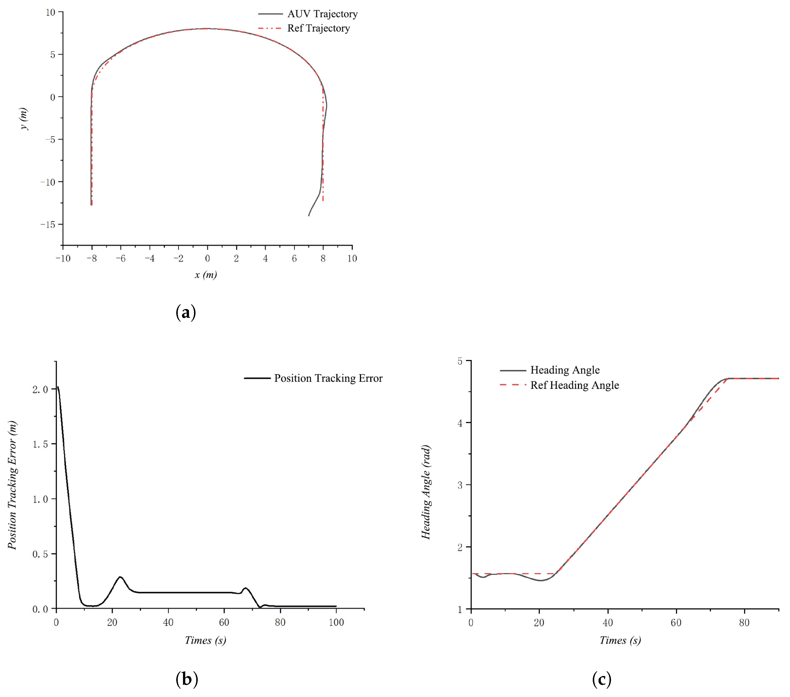
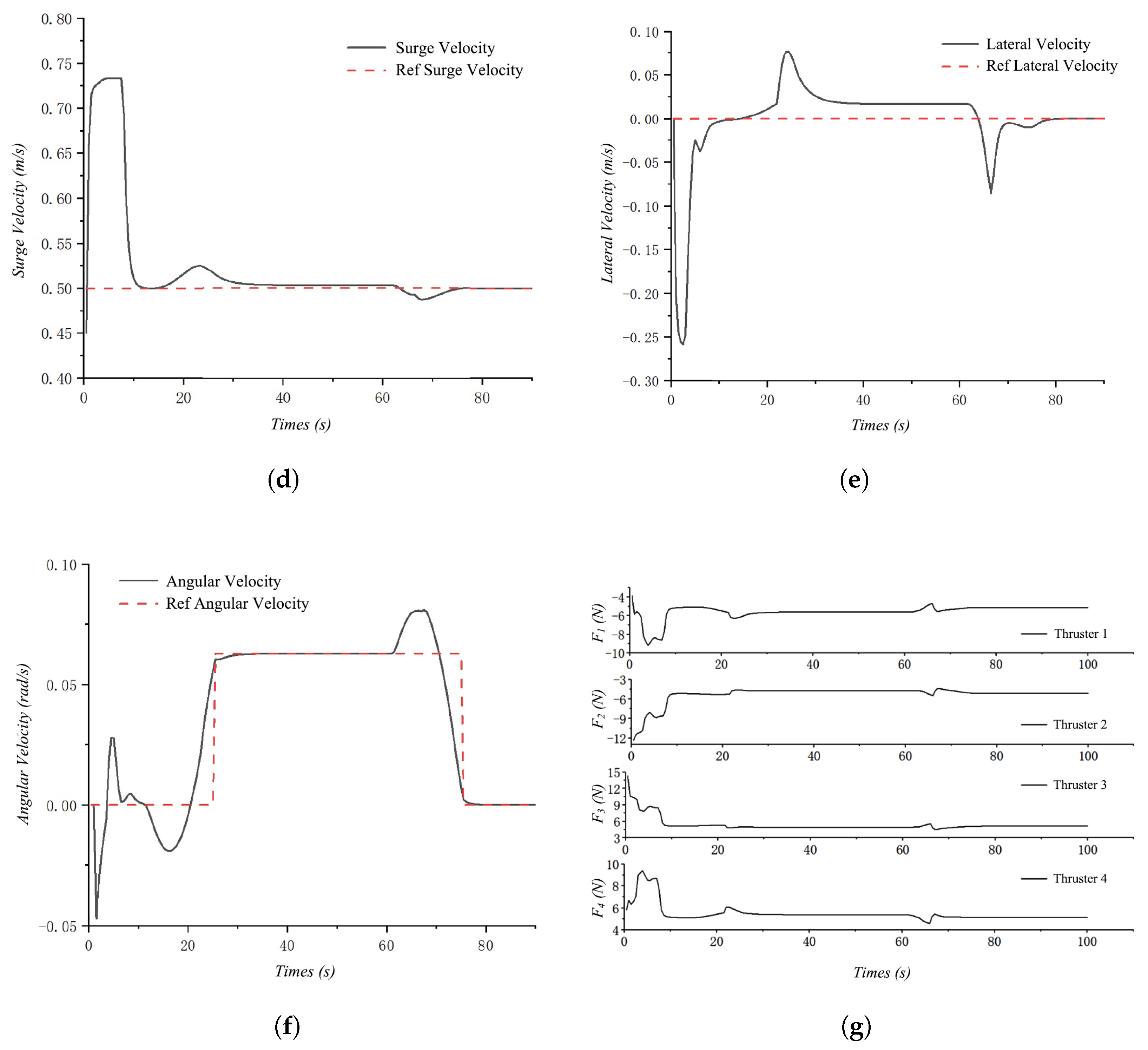
The simulation results of the AUV under undisturbed conditions are shown in Figure 2, with the surge velocity, sway velocity, yaw rate, position tracking error, and heading angle depicted as follows. From the figure, it can be seen that the tracking error of the AUV eventually converges to around 0.02 m. This is due to the conservatism introduced by the limited prediction horizon of the model, which treats the tracking error as a cost in the optimization process. It is also noted that under equal weight conditions, the angular velocity tracking error converges to zero first, while the lateral velocity tracking error converges last. This indicates that the AUV requires the least thrust cost to achieve angular velocity tracking and the most thrust cost for lateral velocity tracking, which is consistent with the hydrodynamic characteristics of the AUV.

4.1.3. Simulation Results Under Disturbances and Uncertainties

To validate the robustness of the controller, external disturbances and model uncertainties need to be introduced in the simulation. These factors are unknown to the controller. First, a fixed external disturbance is applied to the AUV. This disturbance acts on the AUV in the form of an external force, which has two components. The magnitudes of the components and the direction angle of the resultant force are as shown in the following equation:
D X = 10 D Y = 5 γ = a r c t a n D X D Y
To conveniently incorporate the aforementioned disturbances into the AUV model, they also need to be transformed into the body-fixed coordinate system of the AUV.
Δ x Δ y Δ ψ Δ u Δ v Δ r = T e 0 0 0 D X c o s ( γ ψ ) m 11 D Y s i n ( γ ψ ) m 22 0
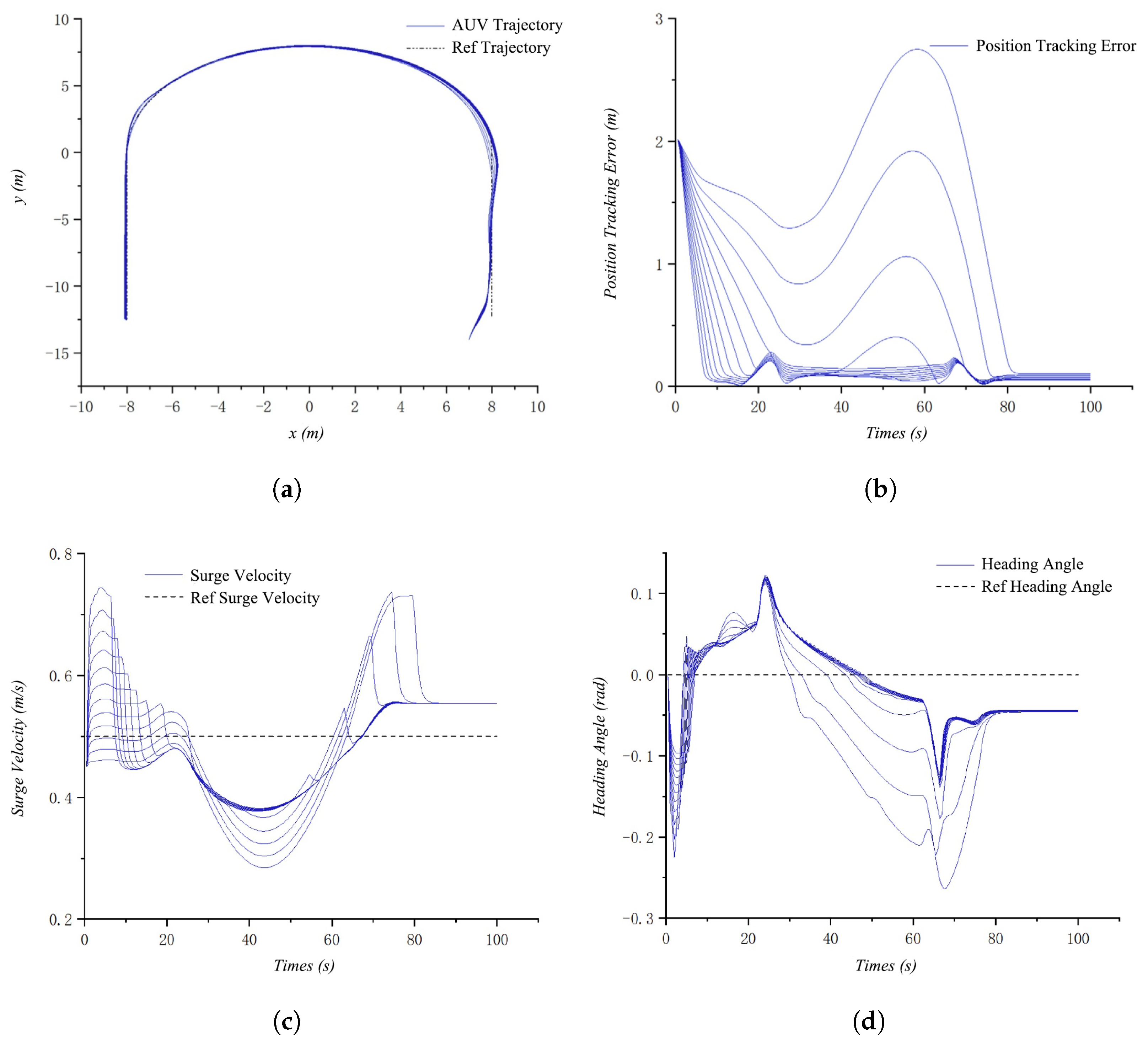
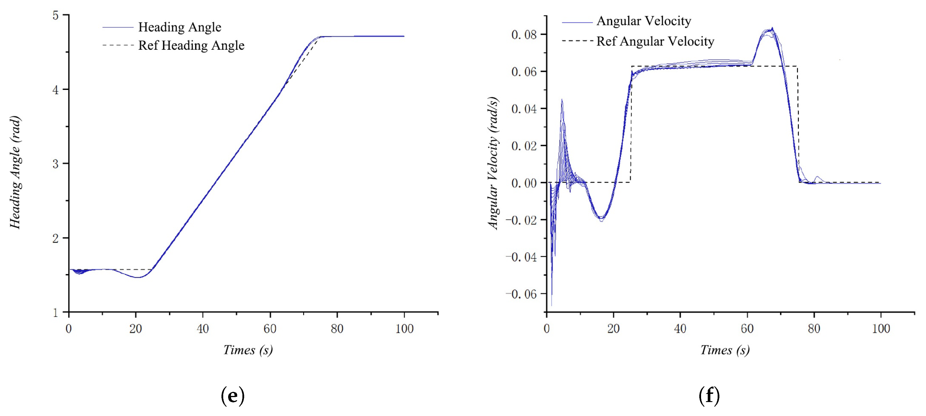
During the trajectory tracking process of the AUV, in addition to external environmental disturbances, the issue of model uncertainty is also encountered. To make the simulation experiment as close to reality as possible, on the basis of existing external disturbances, a rigid body rotational inertia uncertainty of −25% to 25% and an added rotational inertia uncertainty of −35% to 35% were imposed on the AUV’s dynamic model. The simulation results are shown in Figure 3.
After 80 s into the simulation, during a relatively stable straight section, the AUV compensated for the lateral flow disturbance by moving diagonally, sacrificing speed tracking error to ensure the convergence of position tracking error. This demonstrates that the weight settings for the AUV’s position, attitude, and velocity in this paper are effective. When faced with model uncertainties, the controller exhibits good robustness, with only a significant process tracking error when the uncertainty is −30%, and the final tracking effect achieves convergence.
As shown in Figure 3b,c, the controller maintains good tracking performance despite the external disturbances. It is worth noting that a deviation appears between the actual surge velocity and its reference value. This is an intended and correct outcome of the controller’s optimization priorities. To maintain the high-priority trajectory path (position error, weight = 5) against the significant disturbance, the controller correctly sacrifices the lower-priority surge velocity tracking (velocity error, weight = 1). This demonstrates the controller’s effectiveness in successfully managing and prioritizing control objectives in the presence of external disturbances.

4.1.4. Simulation Results with Small Obstacles

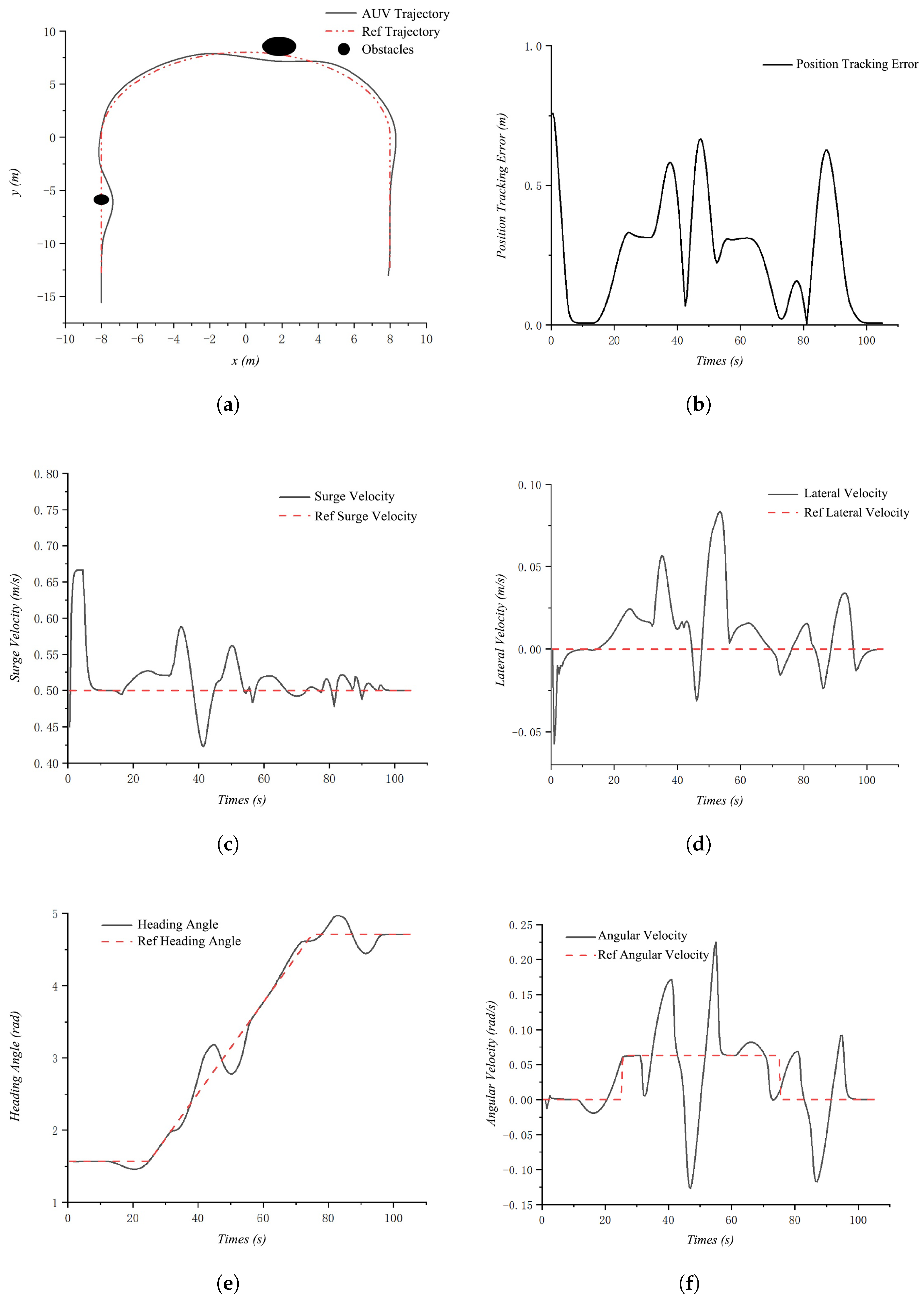
For small obstacles that the AUV can avoid without significantly deviating from the reference trajectory, the exclusion can be achieved by incorporating system constraints into the solution space. In this paper, it is assumed that the obstacles have been identified and their areas have been mathematically defined. Two obstacles are designated as π 1 = β ( 2 , 8 , 1 ) and π 2 = β ( 8 , 6 , 0.5 ) , respectively. The simulation results and the system states during the process are shown in Figure 4.
The simulation results clearly demonstrate the trajectory tracking controller’s ability to autonomously avoid obstacles. Without the need to replan the trajectory, the controller achieves a collision-free path that closely follows the original trajectory while maintaining a certain safety margin. It should be noted that for this controller, the longer the prediction horizon, the larger the range of obstacles it can handle. However, an increase in the prediction horizon significantly increases the computational resources and time required to solve the problem. Therefore, the obstacle handling capability of the MPC method presented in this chapter is limited. To avoid getting stuck in local optima and to handle larger-scale obstacles, it is still necessary to plan the trajectory beforehand. Nevertheless, the characteristics of the MPC controller designed in this paper still provide convenience for the preceding decision-making and planning tasks.

4.2. Validation on a Physical Simulation Platform

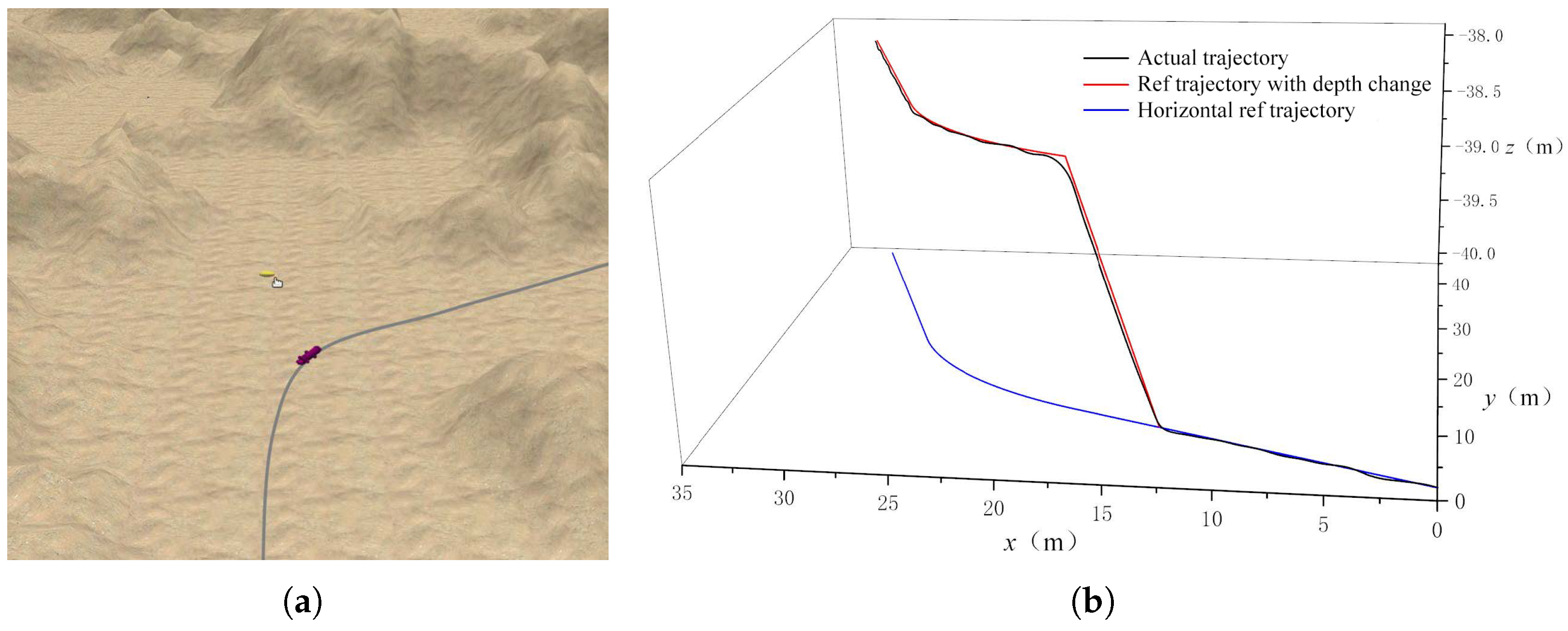
To validate the controller in a more realistic environment, the 3-DOF horizontal plane MPC controller was implemented on a underwater physical simulation platform based on ROS and the Gazebo simulator. This platform models the AUV’s full 6-DOF dynamics, including hydrodynamic effects, sensor noise, and environmental disturbances such as ocean currents.
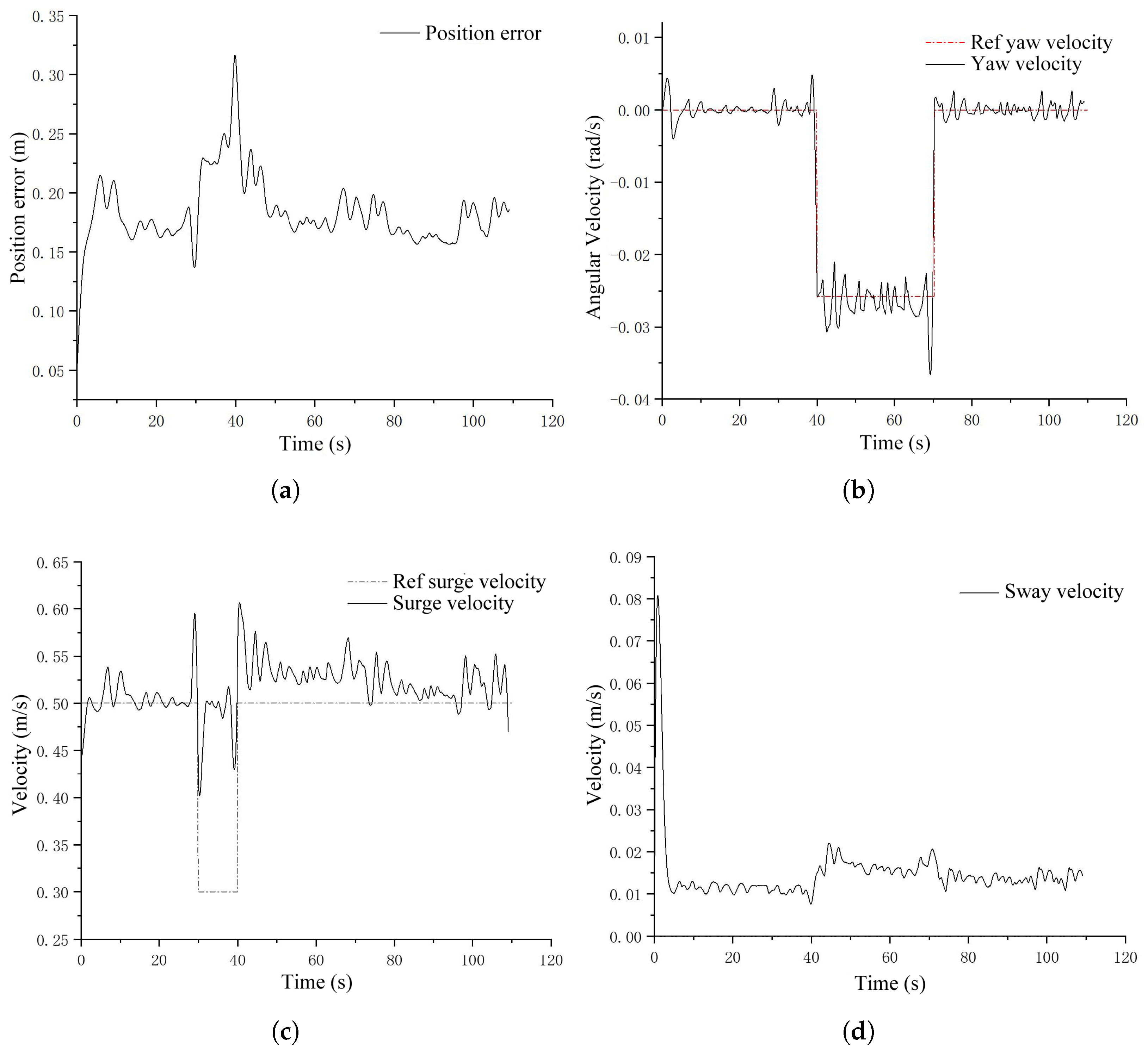
The controller’s task was to track a 3D reference trajectory, with the depth component managed by a separate controller. As shown in Figure 5, the AUV successfully tracks the reference trajectory despite the complex 6-DOF coupling dynamics and external disturbances that were not modeled in the 3-DOF controller. The system state errors, shown in Figure 6, remain bounded and stable, demonstrating the robustness of the 3-DOF controller for its primary task even when operating within a more complex, realistic system.

4.3. Physical Experiment

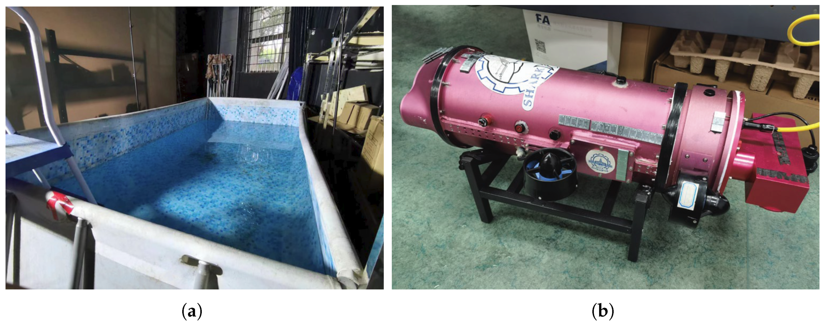
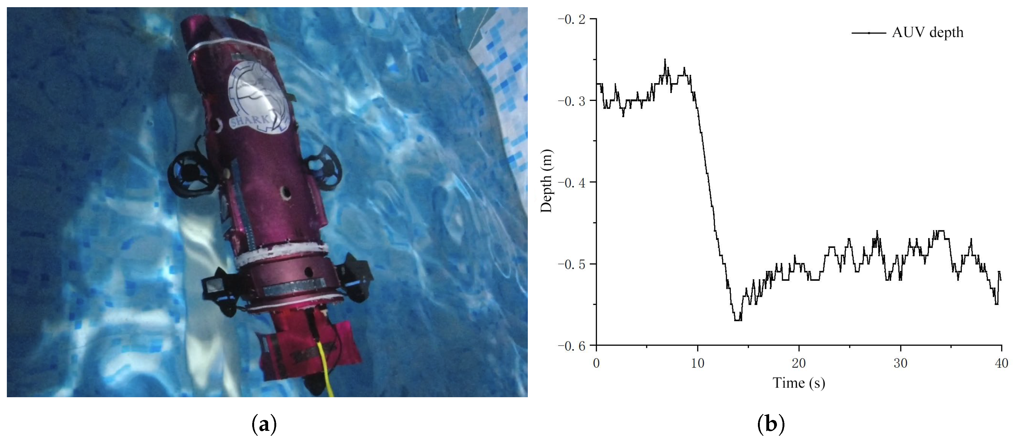
To confirm the practical feasibility of the MPC framework on the actual hardware, experiments were conducted using the AUV prototype (the same model used for the hydrodynamic analysis) in a 4.2 m × 2 m × 1.25 m laboratory test tank, as Figure 7 shows.
For this validation, the MPC controller (using the same modeling, constraint, and optimization principles) was implemented for a depth control task. The AUV was commanded to track a step change in depth from −0.3 m to −0.5 m. The experiment was conducted first in calm water and then repeated while manually generating surface waves (approx. 0.1 m height) to simulate real-world disturbances.
As shown in Figure 8, the controller successfully tracks the new depth setpoint in approximately 5 s, achieving a steady-state error of less than 0.05 m even in the presence of the wave disturbances. This physical test confirms that the proposed MPC formulation is computationally feasible for real-time operation on the AUV’s hardware and is robust to unmodeled physical disturbances.

5. Conclusions

This paper proposed a robust MPC framework to address the significant control challenges in AUV trajectory tracking, namely external disturbances, model uncertainties, and system constraints. The controller was specifically designed to handle practical actuator limitations by constraining both the control input (propeller force) and its rate of change (force increment), ensuring the physical achievability of the control signal. Furthermore, by integrating online updates of the system’s state constraints, the controller successfully achieved autonomous obstacle avoidance. Simulation results, validated under significant disturbances and model uncertainties, demonstrated the controller’s effectiveness and robustness in achieving all control objectives. The primary advantage of this proposed framework lies in its holistic and practical approach. By simultaneously managing hardware-protection constraints (force and rate-of-change) and dynamic environmental constraints within a single optimization, the controller demonstrates a high degree of robustness and practical feasibility. The inclusion of rate-of-change constraints, in particular, ensures smoother control and aligns the algorithm with real-world hardware requirements often overlooked in theoretical studies.
However, several limitations are acknowledged, which pave the way for future research. Firstly, while the controller’s stability was demonstrated empirically through simulation, a formal, rigorous proof of stability (e.g., a Lyapunov-based analysis) for the constrained nonlinear system under persistent disturbances was not provided. Secondly, the obstacle avoidance method, which relies on online-updated state constraints, inherently supports time-varying obstacle regions and is thus effective for static and slow-moving obstacles. However, the current framework does not include a motion prediction model for the obstacles themselves. Therefore, it has not been validated against fast-moving or highly unpredictable obstacles, which would require integration with a dedicated obstacle motion prediction algorithm. This integration is a key direction for future work. Finally, the computational load of MPC, while manageable in simulation, remains a key challenge for implementation on computationally constrained embedded hardware.
Future work will, therefore, focus on three main directions: (1) Developing a formal stability and robustness analysis for the proposed MPC scheme, potentially using terminal constraints or tube-based methods. (2) Integrating the controller with a motion prediction model to handle dynamic obstacle avoidance. (3) Investigating computationally efficient optimization algorithms to facilitate real-time implementation on the AUV’s onboard computer.

Author Contributions

Conceptualization, L.D. and D.Z.; methodology, L.D. and D.Z.; software, S.W. and X.Z.; validation, G.N. and X.Z.; formal analysis, L.D.; investigation, L.D. and D.Z.; resources, D.Z.; data curation, D.Z. and S.W.; writing—original draft, L.D., D.Z. and S.W.; writing—review and editing, G.N., X.Z. and S.W.; visualization, D.Z. and S.W.; supervision, X.W.; project administration, X.W.; funding acquisition, L.D. and X.W. All authors have read and agreed to the published version of the manuscript.

Funding

The work is supported by the Shenzhen Science and Technology Major Program (KJZD20231023100459001).

Data Availability Statement

The original contributions presented in this study are included in the article. Further inquiries can be directed to the corresponding author.

Conflicts of Interest

Authors Libo Dai, Guoping Nie and Xiaoyu Zhu were employed by the company China Offshore Fugro Geosolutions (Shenzhen) Co., Ltd. The remaining authors declare that the research was conducted in the absence of any commercial or financial relationships that could be construed as a potential conflict of interest.

References

  1. Li, D.; Du, L. Auv trajectory tracking models and control strategies: A review. J. Mar. Sci. Eng. 2021, 9, 1020. [Google Scholar] [CrossRef]
  2. Lei, M.; Li, Y.; Pang, S. Extended state observer-based composite-system control for trajectory tracking of underactuated AUVs. Appl. Ocean Res. 2021, 112, 102694. [Google Scholar] [CrossRef]
  3. Thanh, P.N.N.; Tam, P.M.; Anh, H.H.P. A new approach for three-dimensional trajectory tracking control of under-actuated AUVs with model uncertainties. Ocean Eng. 2021, 228, 108951. [Google Scholar] [CrossRef]
  4. Shen, C.; Shi, Y.; Buckham, B. Trajectory tracking control of an autonomous underwater vehicle using Lyapunov-based model predictive control. IEEE Trans. Ind. Electron. 2017, 65, 5796–5805. [Google Scholar] [CrossRef]
  5. Shojaei, K.; Arefi, M.M. On the neuro-adaptive feedback linearising control of underactuated autonomous underwater vehicles in three-dimensional space. IET Control Theory Appl. 2015, 9, 1264–1273. [Google Scholar] [CrossRef]
  6. Abdelaal, M.; Fränzle, M.; Hahn, A. Nonlinear Model Predictive Control for trajectory tracking and collision avoidance of underactuated vessels with disturbances. Ocean Eng. 2018, 160, 168–180. [Google Scholar] [CrossRef]
  7. Raffo, G.V.; Ortega, M.G.; Rubio, F.R. MPC with nonlinear H control for path tracking of a quad-rotor helicopter. IFAC Proc. Vol. 2008, 41, 8564–8569. [Google Scholar] [CrossRef]
  8. Wu, G.X.; Ding, Y.; Tahsin, T.; Atilla, I. Adaptive neural network and extended state observer-based non-singular terminal sliding modetracking control for an underactuated USV with unknown uncertainties. Appl. Ocean Res. 2023, 135, 103560. [Google Scholar] [CrossRef]
  9. Li, J.; Xiang, X.; Dong, D.; Yang, S. Prescribed time observer based trajectory tracking control of autonomous underwater vehicle with tracking error constraints. Ocean Eng. 2023, 274, 114018. [Google Scholar] [CrossRef]
  10. Duan, K.; Fong, S.; Chen, C.P. Reinforcement learning based model-free optimized trajectory tracking strategy design for an AUV. Neurocomputing 2022, 469, 289–297. [Google Scholar] [CrossRef]
  11. Bingul, Z.; Gul, K. Intelligent-PID with PD feedforward trajectory tracking control of an autonomous underwater vehicle. Machines 2023, 11, 300. [Google Scholar] [CrossRef]
  12. Yao, Q. Fixed-time trajectory tracking control for unmanned surface vessels in the presence of model uncertainties and external disturbances. Int. J. Control 2022, 95, 1133–1143. [Google Scholar] [CrossRef]
  13. Wang, T.; Liu, Y.; Zhang, X. Extended state observer-based fixed-time trajectory tracking control of autonomous surface vessels with uncertainties and output constraints. ISA Trans. 2022, 128, 174–183. [Google Scholar] [CrossRef] [PubMed]
  14. Fan, Y.; Qiu, B.; Liu, L.; Yang, Y. Global fixed-time trajectory tracking control of underactuated USV based on fixed-time extended state observer. ISA Trans. 2023, 132, 267–277. [Google Scholar] [CrossRef]
  15. Batkovic, I.; Ali, M.; Falcone, P.; Zanon, M. Safe trajectory tracking in uncertain environments. IEEE Trans. Autom. Control 2022, 68, 4204–4217. [Google Scholar] [CrossRef]
  16. Chen, D.; Zhang, J.; Li, Z. A novel fixed-time trajectory tracking strategy of unmanned surface vessel based on the fractional sliding mode control method. Electronics 2022, 11, 726. [Google Scholar] [CrossRef]
  17. Bao, H.; Zhu, H. Modeling and trajectory tracking model predictive control novel method of AUV based on CFD data. Sensors 2022, 22, 4234. [Google Scholar] [CrossRef]
  18. Li, M.; Xie, W.; Wang, Y.; Hu, X. Prescribed performance trajectory tracking fault-tolerant control for dynamic positioning vessels under velocity constraints. Appl. Math. Comput. 2022, 431, 127348. [Google Scholar] [CrossRef]
  19. Wu, Z.; Wang, Q.; Huang, H. Adaptive neural networks trajectory tracking control for autonomous underwater helicopters with prescribed performance. Ocean Eng. 2022, 264, 112519. [Google Scholar] [CrossRef]
  20. Zhou, B.; Su, Y.; Huang, B.; Wang, W.; Zhang, E. Trajectory tracking control for autonomous underwater vehicles under quantized state feedback and ocean disturbances. Ocean Eng. 2022, 256, 111500. [Google Scholar] [CrossRef]
  21. He, L.; Xie, M.; Zhang, Y. A Review of Path Following, Trajectory Tracking, and Formation Control for Autonomous Underwater Vehicles. Drones 2025, 9, 286. [Google Scholar] [CrossRef]
  22. Liu, T.; Zhao, J.; Huang, J. A Gaussian-Process-Based Model Predictive Control Approach for Trajectory Tracking and Obstacle Avoidance in Autonomous Underwater Vehicles. J. Mar. Sci. Eng. 2024, 12, 676. [Google Scholar] [CrossRef]
  23. Li, J.; Xia, Y.; Xu, G.; Guo, Z.; Han, H.; Wu, Z.; Xu, K. Enhanced three-dimensional trajectory tracking control for AUVs in variable operating conditions using FMPC-FTTSMC. Ocean Eng. 2024, 310, 118805. [Google Scholar] [CrossRef]
  24. Li, B.; Gao, X.; Huang, H.; Yang, H. Improved adaptive twisting sliding mode control for trajectory tracking of an AUV subject to uncertainties. Ocean Eng. 2024, 297, 116204. [Google Scholar] [CrossRef]
  25. Hong, L.; Wang, X.; Zhang, D.; Xu, H. Numerical Study on Hydrodynamic Coefficient Estimation of an Underactuated Underwater Vehicle. J. Mar. Sci. Eng. 2022, 10, 1049. [Google Scholar] [CrossRef]
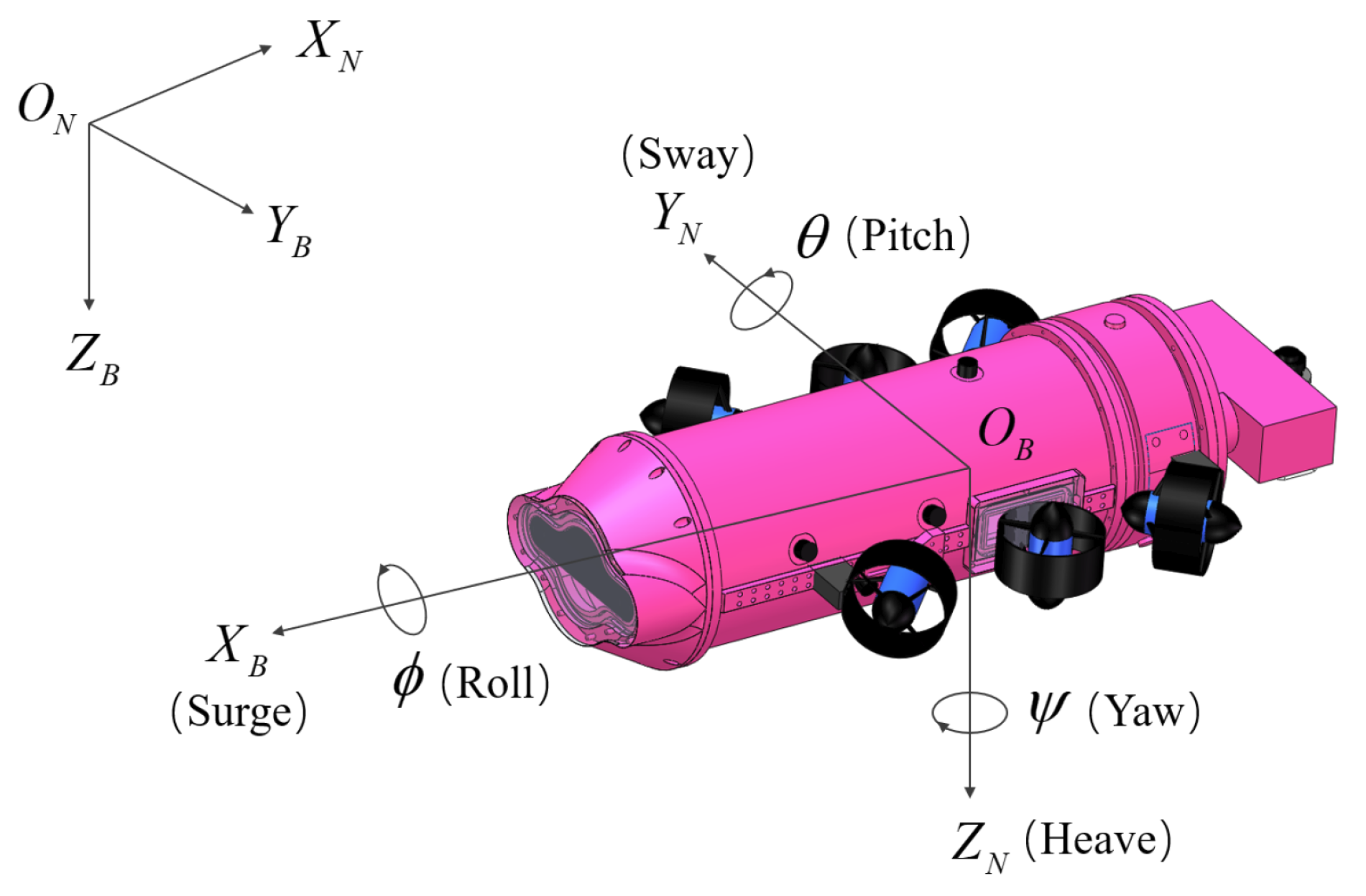
Figure 1. The coordinate system for AUV.
Jmse 13 02210 g001
Figure 2. Trajectory tracking simulation results under ideal conditions. (a) The AUV trajectory converges smoothly to the reference trajectory; (b) Position tracking error, showing convergence to a small, non-zero steady-state error (≈0.02 m); (c) Heading angle; (d) Surge velocity; (e) Lateral velocity; (f) Angular velocity; (g) Thruster Force.
Jmse 13 02210 g002aJmse 13 02210 g002b
Figure 3. Trajectory tracking simulation results under disturbances and uncertainties. (a) The AUV trajectory successfully tracks the reference path despite the disturbances; (b) Position tracking error remains bounded; (c) Surge velocity; (d) Lateral velocity; (e) Heading angle; (f) Angular velocity.
Jmse 13 02210 g003aJmse 13 02210 g003b
Figure 4. Trajectory tracking simulation results with small obstacles. (a) The AUV trajectory deviates from the reference trajectory to avoid both obstacles; (b) The position tracking error, showing spikes as the AUV proactively navigates around the obstacles. (c) Surge velocity; (d) Lateral velocity; (e) Heading angle; (f) Angular velocity.
Jmse 13 02210 g004
Figure 5. ROS-based simulation on AUV Trajectory Tracking. (a) Overhead view of the AUV tracking the 3D reference trajectory (grey curve) in the simulated environment; (b) AUV successfully following the path despite 6-DOF coupling and unmodeled disturbances.
Jmse 13 02210 g005
Figure 6. State tracking errors from the simulation. (a) Horizontal position; (b) Yaw velocity; (c) Surge velocity; (d) Sway velocity.
Jmse 13 02210 g006
Figure 7. Experiment preparation. (a) Water tank; (b) AUV prototype.
Jmse 13 02210 g007
Figure 8. Experiment result. (a) AUV running depth control; (b) Depth state.
Jmse 13 02210 g008
Table 1. Solution steps for the algorithm.
StepActions
1Obtain the state-space equation model of the system.
2Use the fourth-order Runge–Kutta method to discretize the system’s state-space equations and write them in incremental form.
3Set system constraints such as pose and velocity, input constraints such as thruster thrust.
4Set controller parameters such as sampling interval, prediction horizon, and control horizon.
5Define the system cost function arg min J
6For (Control task not completed)
7Update the parameters in the system state matrix related to the current state.
8Under the given constraints, solve for the optimal control input sequence Δ U k at the current time k to minimize the cost function.
9Obtain the first control input from the optimal control input sequence  Δ U k .
10Execute the control input u k + 1 within the control horizon.
11End
Disclaimer/Publisher’s Note: The statements, opinions and data contained in all publications are solely those of the individual author(s) and contributor(s) and not of MDPI and/or the editor(s). MDPI and/or the editor(s) disclaim responsibility for any injury to people or property resulting from any ideas, methods, instructions or products referred to in the content.