Article

Upgrade and Application of the Dynamic Positioning System for a Small Waterplane Area Twin Hull Vessel

1
South China Sea Institute of Oceanology, Chinese Academy of Sciences, Guangzhou 510301, China
2
State Key Laboratory of Tropical Oceanography, South China Sea Institute of Oceanology, Chinese Academy of Sciences, Guangzhou 510301, China
3
Marine Design and Research Institute of China, Shanghai 200011, China
*
Author to whom correspondence should be addressed.
J. Mar. Sci. Eng. 2025, 13(11), 2198; https://doi.org/10.3390/jmse13112198
Submission received: 16 October 2025 / Revised: 8 November 2025 / Accepted: 17 November 2025 / Published: 19 November 2025
(This article belongs to the Section Ocean Engineering)

Abstract

The small waterplane area twin hull (SWATH) is a type of high-performance vessel known for its excellent seakeeping performance, remarkable maneuverability, and high lateral stability. These advantages have led to its growing application in scientific research ships. Since many research operations require a vessel to maintain a fixed position, Dynamic Positioning Systems (DPSs) are essential. To better support diverse scientific tasks, the R/V SHIYAN 1 was upgraded with an enhanced dynamic positioning system. A ship motion model was established after comprehensively accounting for environmental factors such as wind, waves, and currents. By automatically controlling three actuators, the system successfully achieved effective dynamic positioning. In comparative tests conducted under conditions of wind speed at 13.4 m/s, wave height at 3.2 m, and current at 0.2 m/s, the power system was able to maintain a positioning radius within 5 m. Analysis of data from three dynamic positioning experiments revealed that wave loads had the most significant impact on positioning accuracy, followed by wind loads, while ocean current loads had the least influence. This upgrade not only improves the vessel’s operational capability but also enhances its effectiveness in marine scientific exploration.

1. Introduction

The small waterplane area twin hull (SWATH) is a novel type of high-performance vessel. Its twin-hull structure confers excellent seakeeping performance, maneuverability, and transverse stability. Compared to monohulls, SWATH vessels offer superior motion performance [1,2,3,4,5,6]. In 1978, the United States conducted seakeeping experiments with the SSP Kaimalino. The 220-ton vessel exhibited roll motions in random seas with amplitudes comparable to those of a 3100-ton warship, while demonstrating superior roll performance. Japan’s “Sea Gulf” SWATH, built in 1979, experienced a speed loss of less than 2% at 24 knots in sea state 4, and approximately 5% in sea state 5 [7]. Dubrovsky et al. [8] applied scale effects to analyze the resistance components and residual resistance factors of SWATH vessels, noting that while a smaller waterplane area ensures favorable wave resistance, it also increases susceptibility of heave and pitch motions to external loads. Davis [9], studying the performance of SWATH vessels in irregular waves, found that when the encounter frequency approaches the maximum response frequency, pitch and heave motions intensify for hulls with vertical struts, and wave resistance decreases in sea states of level 4 and above. Techet [10] developed an inclined-strut SWATH based on the characteristic of degraded motion performance with vertical struts in certain sea conditions, and investigated its propulsion performance in regular waves at high Reynolds numbers. The study indicated that heave and pitch motions caused the free surface to interact with the inclined struts, generating thrust that could reduce the energy consumption of the SWATH in waves. Qian [11] also studied the motion response and energy consumption of inclined-strut hull forms in regular waves, finding through numerical simulation and experiments that such designs exhibit smaller motion amplitudes and lower wave resistance in regular waves.
As offshore activities extend into deeper waters, a growing number of vessels are being fitted with dynamic positioning (DP) systems [12]. By using only thrusters and propellers, a DP system keeps the vessel at a desired position and heading [13,14]. It offers an effective replacement for traditional mooring systems when mooring is impractical or prohibitively expensive. This functionality is essential for a variety of operations that have become both more frequent and more technically challenging in recent years [15,16,17,18], such as offshore drilling, coring, submarine pipeline installation, dredging [19], cargo transfer from floating production storage and offloading (FPSO) units [20], and station-keeping by offshore support vessels near fixed installations [21].
As a result, there is a pressing need to design and operate more sophisticated DP systems that can achieve precise maneuvering, high operational and environmental efficiency, and long-term reliability [22]. These requirements have spurred the research community to develop increasingly advanced DP control strategies. While early DP systems relied on basic proportional–integral–derivative (PID) controllers to counteract horizontal motion, modern implementations have evolved into highly complex systems that employ multivariable optimal control and Kalman filtering [23,24,25,26,27,28], nonlinear or model predictive control [29,30,31], hybrid control [32,33,34,35], fault-tolerant control [36,37,38], and fuel-efficient operation [39]. For a detailed historical overview of early DP systems, as well as comprehensive reviews of recent progress, readers are referred to Fossen [40] and Sørensen [41].
For surface vessels with dynamic positioning, environmental forces from wind, waves, and currents induce motions in the degrees of freedom of surge, sway, and yaw. The dynamic positioning system is designed to counteract these environmental disturbances and control the vessel’s planar motion. Sea surface wind is not only a primary cause of wave generation but also directly affects the exposed hull and superstructure, inducing adverse motions such as roll and yaw, significantly impacting vessel attitude. Furthermore, random sea surface waves cause turbulence for vessels operating on the horizontal plane. The upgrade of the DP system on R/V SHIYAN 1 enhances its ability to withstand wind, waves, and currents during operations, enabling precise station-keeping. This paper presents an upgraded dynamic positioning system for R/V SHIYAN 1 and demonstrates its superior performance through sea trial results.
This paper is organized as follows. Materials and methods are described in Section 2. The main results are presented in Section 3, and a detailed discussion and summary are provided in Section 4 and Section 5.

2. Materials and Methods

2.1. Mathematical Model of Ship Manoeuvring

A ship’s motion state can be described by its position/orientation and velocity across six degrees of freedom. Surge, sway, and heave correspond to translational motion along the x, y, and z axes in the North–East–Down (NED) coordinate system, represented by velocities u, v, and w in the ship-fixed coordinate system. Roll, pitch, and yaw correspond to rotational motion about the x, y, and z axes in the NED system, represented by angular velocities p, q, and r in the ship-fixed frame. Based on these definitions, a kinematic model is established. Since the ship’s velocities and its position/orientation are defined in different reference frames, a transformation is required to relate pose changes to velocity inputs from the actuators. Using Euler transformations [42], a rotation matrix between the NED and ship-fixed coordinate systems is constructed, yielding the following kinematic model. As this study focuses on the horizontal motion of the vessel, excluding heave, roll, and pitch (which exhibit relatively small changes), the six-degree-of-freedom model is simplified to a three-degree-of-freedom model for surge, sway, and yaw.
δ = J φ ϑ ,
J φ = cos φ sin φ 0 sin φ cos φ 0 0 0 1 ,
where the position state quantity to δ   =   x y φ T , (x,y) is the position of the ship in the coordinate system, φ     π , π is the bow angle of the ship; simplify the speed state variable to ϑ   =   u v r T , representing the velocity and angular velocity of three degrees of freedom, respectively.

2.2. Environmental Load Calculation

Dynamically positioned vessels are subject to combined environmental loads from wind, waves, and currents, causing deviation from their set position. The DP system commands the thrusters to generate forces to counteract these environmental loads, limiting the vessel’s position and heading deviation within specified bounds. The controller uses an extended Kalman filter for optimal estimation of vessel motions and environmental forces from wind, waves and current. Therefore, calculating environmental loads is fundamental to dynamic positioning capability analysis.

2.2.1. Wind Load

Wind load is significant in DP capability calculations, often constituting over 40% of the total load under high wind speeds. The most accurate method for obtaining wind loads is wind tunnel testing; however, this is time-consuming and costly, typically reserved for final design verification. During initial design stages, various organizations employ modular calculation methods. The International Marine Contractors Association (IMCA, [43]) provides guidelines for DP analysis, including a simplified method for wind load calculation [13]. When wind acts along the X or Y axis of the hull, the wind load can be calculated using Equation (3):
F wdx   =   C wd C s C h A T V wd 2 F wdy   =   C wd C s C h A L V wd 2 F wdz   =   F wy X wdc
where Fwdx, Fwdy, and Fwdz represent the longitudinal force, lateral force, and yaw moment acting on the hull, respectively; Cwd is the wind load coefficient (0.615 for force in Newtons); Cs is the shape coefficient; Ch is the height coefficient; AT is the lateral projected area above the waterline; AL is the longitudinal projected area above the waterline; and Xwdc is the lever arm from the lateral force application point to the center of rotation. Wind loads from other directions (e.g., 0–90 degrees) can be obtained by interpolation, as shown in Equation (4):
F wd   =   F wdy 90 2 sin 2 1   +   sin 2 + F wdx 0 2 cos 2 1   +   cos 2   ,
where is the wind direction relative to the ship’s bow; F wd is the resultant wind force for any relative wind direction; F wdx 0 is the longitudinal force component at 0° relative wind direction; and F wdy 90 is the lateral force component at 90° relative wind direction.

2.2.2. Wave Load

Wave load refers to the force exerted by ocean waves on marine structures, arising from the relative motion between water particles and the structure, characterized by stochastic properties. It includes hydrodynamic pressure, inertial forces, bending moments, shear forces, and torsional moments, categorized into dynamic, steady-state, and transient wave loads. Wave load intensity depends on wave height, period, water depth, and structural form. Forces become significant for wave heights around 0.5 m. Morrison’s equation [44] is applicable when the structural member diameter is less than 20% of the wavelength; diffraction theory should be used for larger ratios.
Wave forces on ships consist of two main components: second-order low-frequency wave drift forces causing low-frequency drift motion, and first-order high-frequency wave exciting forces causing high-frequency oscillations about the equilibrium position. Theoretically, first-order wave forces can be obtained by integrating fluid dynamic pressure over the wetted surface of the ship hull [45]:
X wh = V p x b dV Y wh = V p y b dV N wh = Vv p x b y b p y b x b dV ,
The second-order drift force τ ς can be calculated by second-order low-frequency waves on the ship’s hull.
X ς = ρ g L c o s γ i = 1 N C Xwd 2 π ω i 2 gL S ω i ω Y ς = ρ g L s i n γ i = 1 N C Ywd 2 π ω i 2 gL S ω i ω N ς = ρ g L s i n γ i = 1 N C Nwd 2 π ω i 2 gL S ω i ω ,
C Xwd = 0.05     0.2 β i / L + 0.75 β i / L 2 0.51 β i / L 3 C Ywd = 0.46 + 6.83 β i / L     15.65 β i / L 2 + 8.44 β i / L 3 C Nwd = 0.11 + 0.68 β i / L     0.79 β i / L 2 + 0.21 β i / L 3 ,
τ ς = X ς , Y ς , N ς T ,
Here, γ is the angle between the bow of the ship and the direction of the waves. L is the length of the hull waterline and γ i   =   2 ω i 2 / g is the corresponding wavelength. g represents the acceleration due to gravity.

2.2.3. Current Load

In DP capability analysis, current speeds are typically low (≤6 knots), where the dominant loads on the hull are frictional resistance and viscous pressure resistance. Accurate methods for obtaining current loads include towing tank tests and CFD simulations. For initial design, IMCA provides convenient calculation methods [46], offering dimensionless current load coefficients for various ship types and current directions (0–180°). The loads for a given current direction α c are:
F cx α c   =   1 2 ρ v c 2 C cx α c B T F cy α c   =   1 2 ρ v c 2 C cy α c L pp T F cn α c   =   1 2 ρ v c 2 C cn α c T L pp 2   ,
where, α c is the current direction relative to the ship’s bow; T is the draft; B is the width of the ship; LPP is the length between perpendicular lines; v c is the flow velocity; ρ is the density of seawater; F cx α c , F cy α c and F cn α c are the longitudinal force, lateral force, and yaw moment, respectively.

3. Results

3.1. Upgrade of the Dynamic Positioning System

3.1.1. R/V SHIYAN 1

The R/V “SHIYAN 1” is China’s first CCS-classified 2500-ton small waterplane area twin hull (SWATH) oceanographic research vessel. It was jointly built by the Institute of Acoustics of the Chinese Academy of Sciences, the South China Sea Institute of Oceanography, and the Shenyang Institute of Automation and was commissioned in 2009. The main dimensions of the R/V SHIYAN 1 are 60.9 m in length and 26 m in beam. It is equipped with three thrusters (Figure 1): one KT-55B1 (Wuhan Kawasaki Marine Machiery Co., Ltd., Wuhan, China) controllable pitch bow thruster (440 kW) located on the starboard bow, and two AMZ 0710LS14 (ABB Marine Service Center, Shanghai, China) variable frequency main propulsion motors (1700 kW each) at the stern, driving fixed-pitch propellers via shaftlines. The vessel’s main characteristics are listed in Table 1.
Key scientific operations requiring DP on research vessels include the following: deployment and retrieval of acoustic observation equipment at fixed points; handling of large buoys and submersible markers; launch and recovery of Autonomous Underwater Vehicles (AUVs) and Remotely Operated Vehicles (ROVs); and operations such as heat flow probe surveys, gravity coring, box coring, multi-net sampling, and stationary CTD profiling. To meet the positioning requirements of marine scientific research and ensure data accuracy, upgrading the dynamic positioning system was imperative.

3.1.2. The MEGA-GUARD System

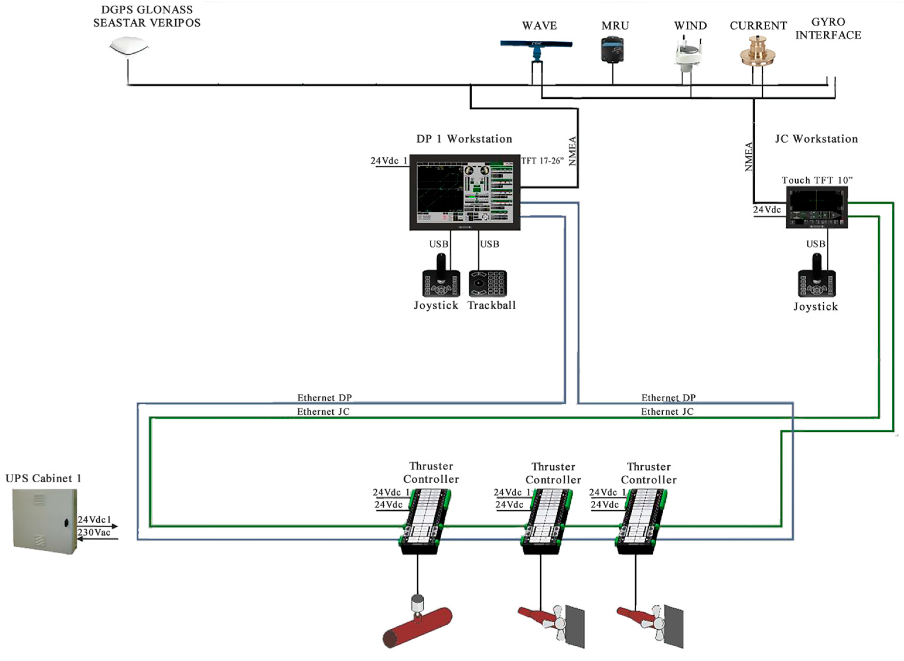
The MEGA-GUARD dynamic positioning system (Figure 2) comprises redundant DP operator workstations and propulsion controllers (one per thruster), interconnected via a redundant DP Ethernet network. The DP workstation’s central processing unit features a high-brightness TFT display interface, redundant DP Ethernet ports, a joystick panel, a trackball panel, and (multiple) 8-channel NMEA input modules connected to sensors, including the gyrocompass, anemometer, position reference systems, and motion reference units. Each thruster has its own dedicated thruster controller, providing redundant DP Ethernet interfaces to the (redundant) DP controller. Per IMO regulations, the power positioning system includes an independent Joystick Control (JC) system, consisting of highly reliable (redundant) JC operator stations and thruster controllers interconnected via a redundant JC Ethernet network. The JC workstation’s central unit consists of a JC controller with a high-brightness TFT interface, redundant JC Ethernet, a joystick panel, a trackball panel, and a 4-channel NMEA input module connected to key sensors.
The MEGA-GUARD system is fully featured and user-friendly. In automatic positioning mode, the DP workstation offers various operational modes: minimum power mode (weathervaning), minimum power mode (positioning circle), joystick manual surge mode, joystick manual sway mode, joystick manual combined surge/sway mode, automatic track-following (low and high speed), and route tracking. The joystick panel provides options for manual joystick control, joystick auto-heading, and auto-heading-only modes. The system also incorporates functions such as load monitoring and blackout prevention, DP real-time capability analysis, and simulation training. Based on the original wind field inputs, the system has incorporated waves and currents as additional environmental variables, ultimately enhancing its positioning capability.

3.2. Application of Offshore Experiments

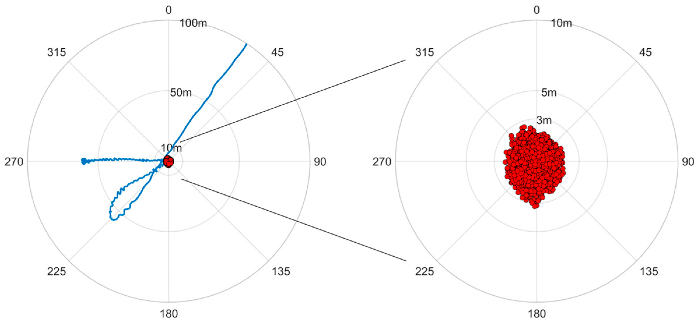
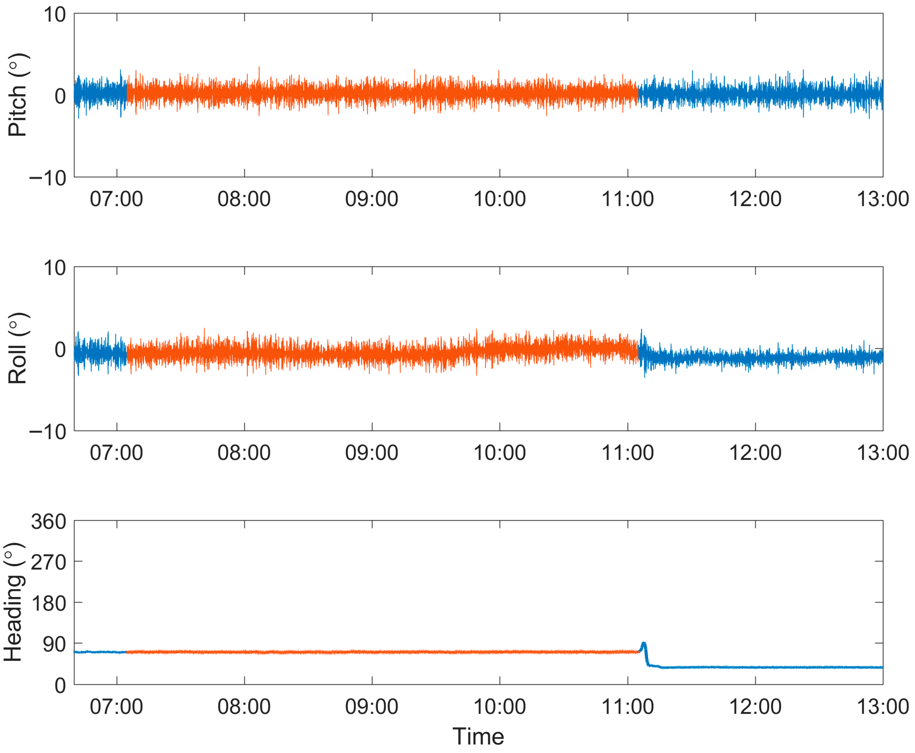
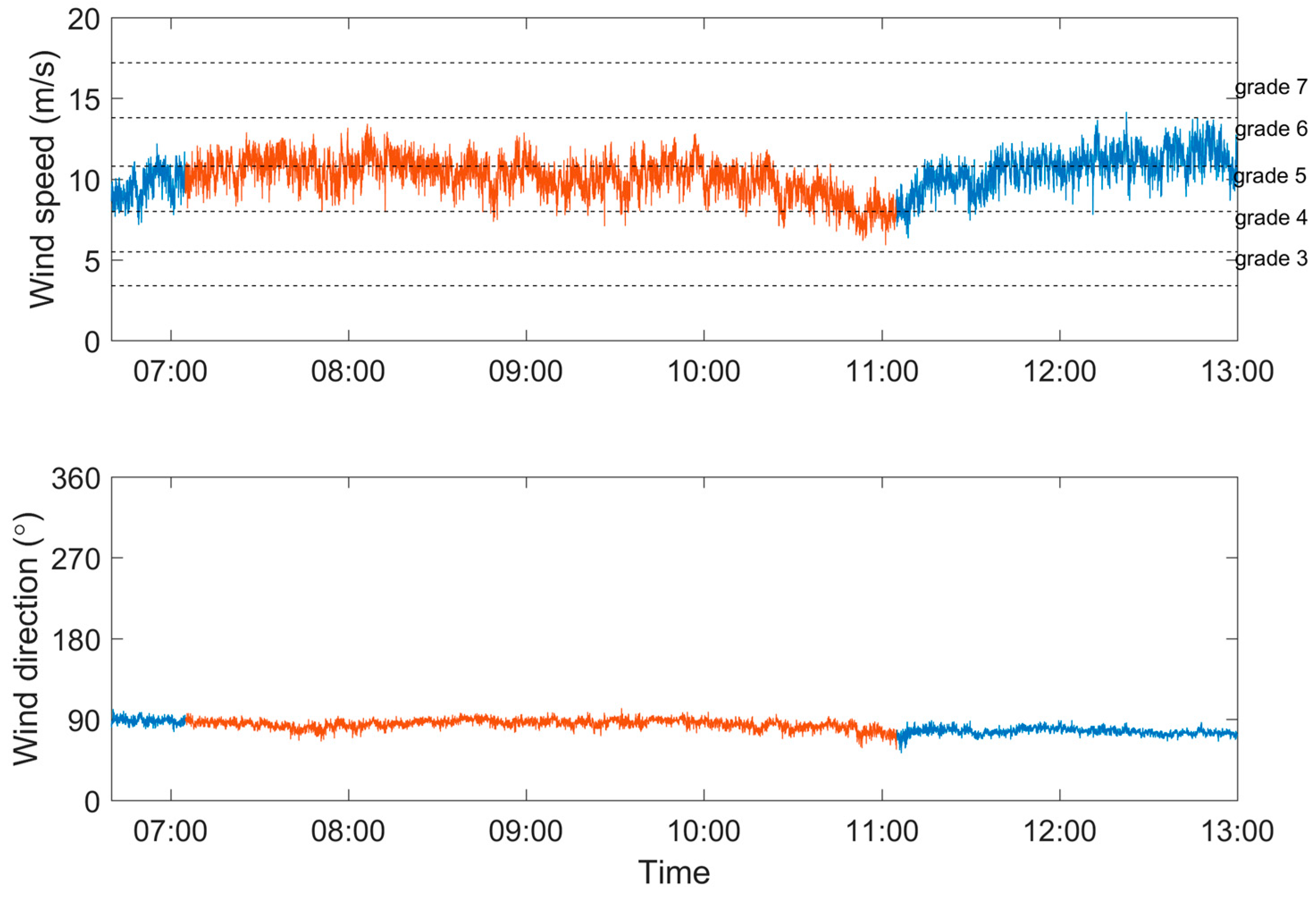
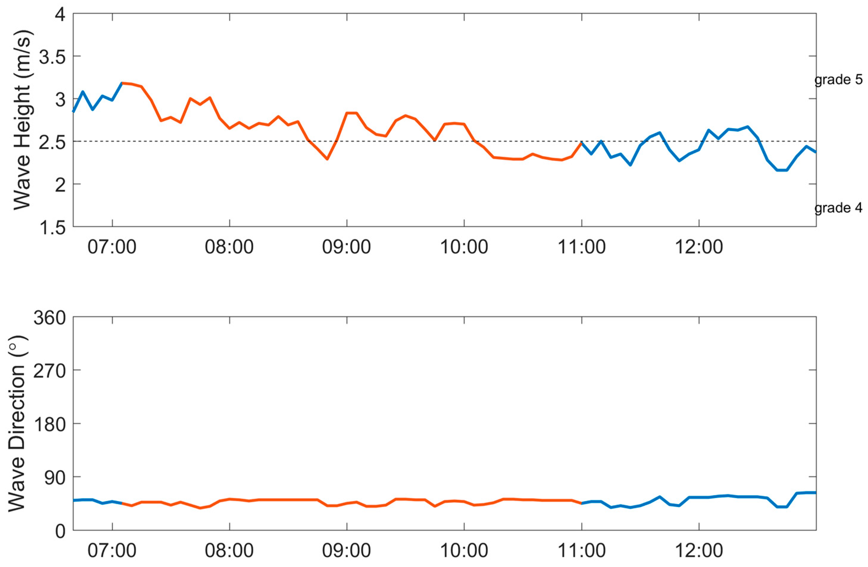
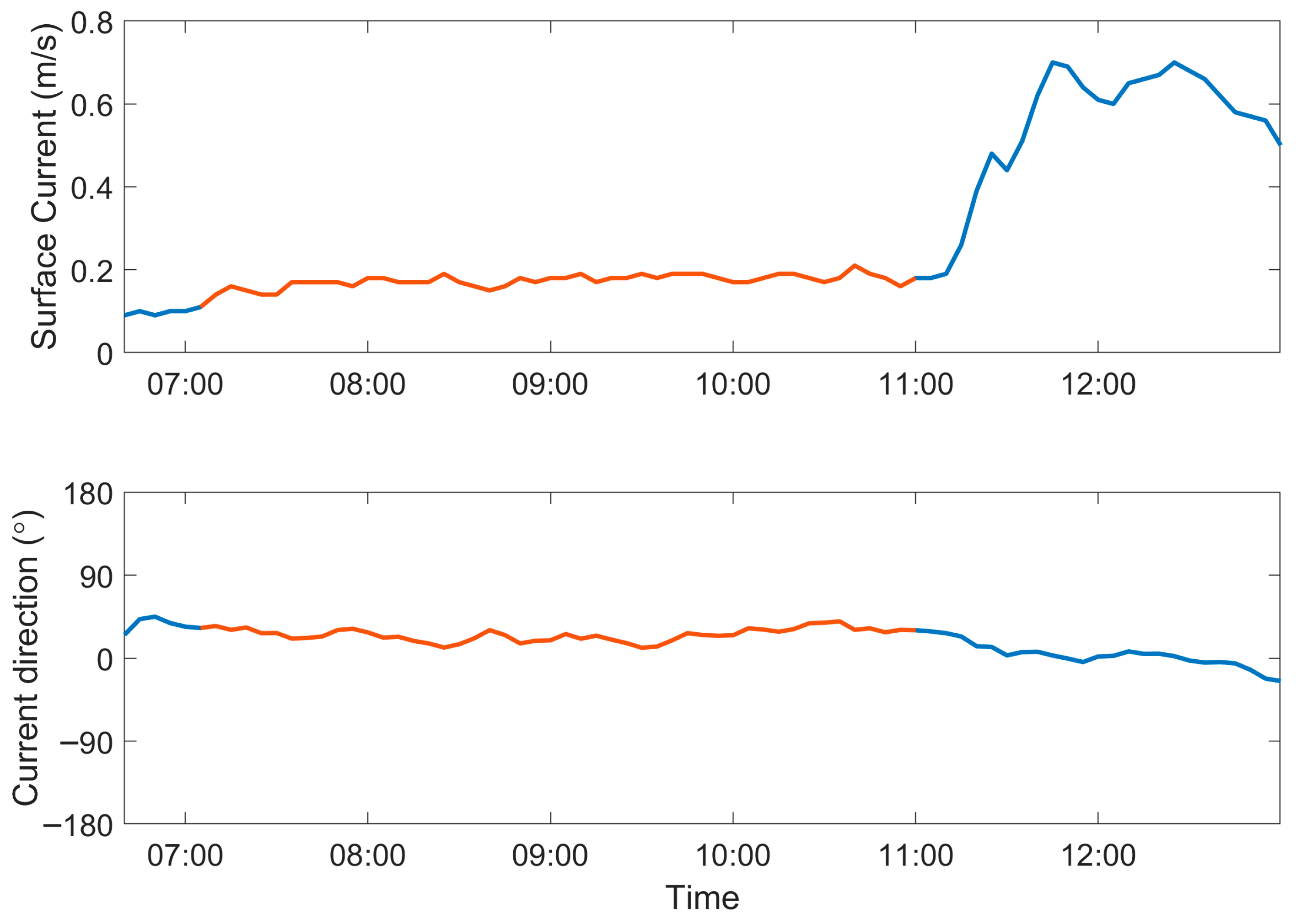
During October 2025, the South China Sea Institute of Oceanology conducted operations in the northern South China Sea under both dynamic positioning (DP) and non-DP conditions, obtaining data on vessel position, vessel attitude, and vessel-recorded meteorological, wave, and current information (Figure 3, Figure 4, Figure 5, Figure 6 and Figure 7). Before activating the dynamic positioning system, the vessel operated in a drifting mode. Influenced by easterly winds (Figure 5), the vessel drifted westward at a speed of approximately 1 knot per hour. Since the vessel was not under dynamic control, its heading continuously varied between 40° and 90° (Figure 4). After the DP system was activated, despite the relatively poor sea conditions (Sea State 4–5), the vessel’s position remained within 5 m of the target center (Figure 3), and its heading stabilized, varying within 5° (Figure 5).
Regarding wind field information, both before and after DP activation, the wind speed varied between 7–15 m/s, predominantly at Force 5–6, with easterly winds prevailing. Wind speed and direction remained relatively stable, indicating that the quality of wind data collected was not affected by the activation of the DP system.
The wave information required for the DP system was provided by wave-measuring radar. During the observation period, sea conditions were relatively high, with wave heights exceeding 2 m, corresponding to Sea State 4–5. After DP activation, wave heights decreased from 3.2 m to 2.3 m, while the wave direction remained largely unchanged at 47°. The average surface current speed was 0.2 m/s, flowing at 26° (Figure 6). After the DP system was deactivated, the measured surface current speed increased, and the flow direction decreased, suggesting that the DP system contributed to the stability of surface current measurements taken by the wave-measuring radar (Figure 7).

4. Discussion

Following the upgrade of the power positioning system on the small waterplane area twin hull vessel, precise position control was achieved. According to DP system design requirements, the vessel should be capable of holding station at any heading under operational sea conditions. However, wind and current directions vary across different sea areas and times. If a research vessel, particularly a catamaran with a large lateral windage area, experiences beam environmental forces, significant lateral thrust is required to maintain position. The control system would command the thrusters to provide counteracting forces, potentially leading to high loads on the bow and stern thrusters. Prolonged operation under such conditions can cause machinery wear. Therefore, whether in Joystick or Auto Position mode, orienting the vessel’s bow towards the prevailing environmental forces (wind and current) is the most efficient station-keeping strategy. As shown in Figure 5, the vessel’s heading stabilized around 70°, which aligned approximately with the wind direction of 90° shown in Figure 6, demonstrating this optimal approach.
The required positioning accuracy varies depending on the type of offshore operation and the depth of the working area. For instance, vessels such as drilling platforms and cable-laying ships operating in shallow waters generally demand higher positioning precision, while those engaged in deep-sea exploration can accommodate lower accuracy. It is understandable that for underwater operations at 3000 m depth, a surface vessel positioning accuracy of 30 m is considered sufficient (resulting in a vertical deviation angle of only 34′). However, for a similar task at 300 m depth, the positioning accuracy must be within 5 m to achieve a comparable deviation. The “Ocean One” research vessel, designed for deep-sea survey and exploration at depths of 3000–6000 m, has a dynamic positioning requirement of 40 m [47].
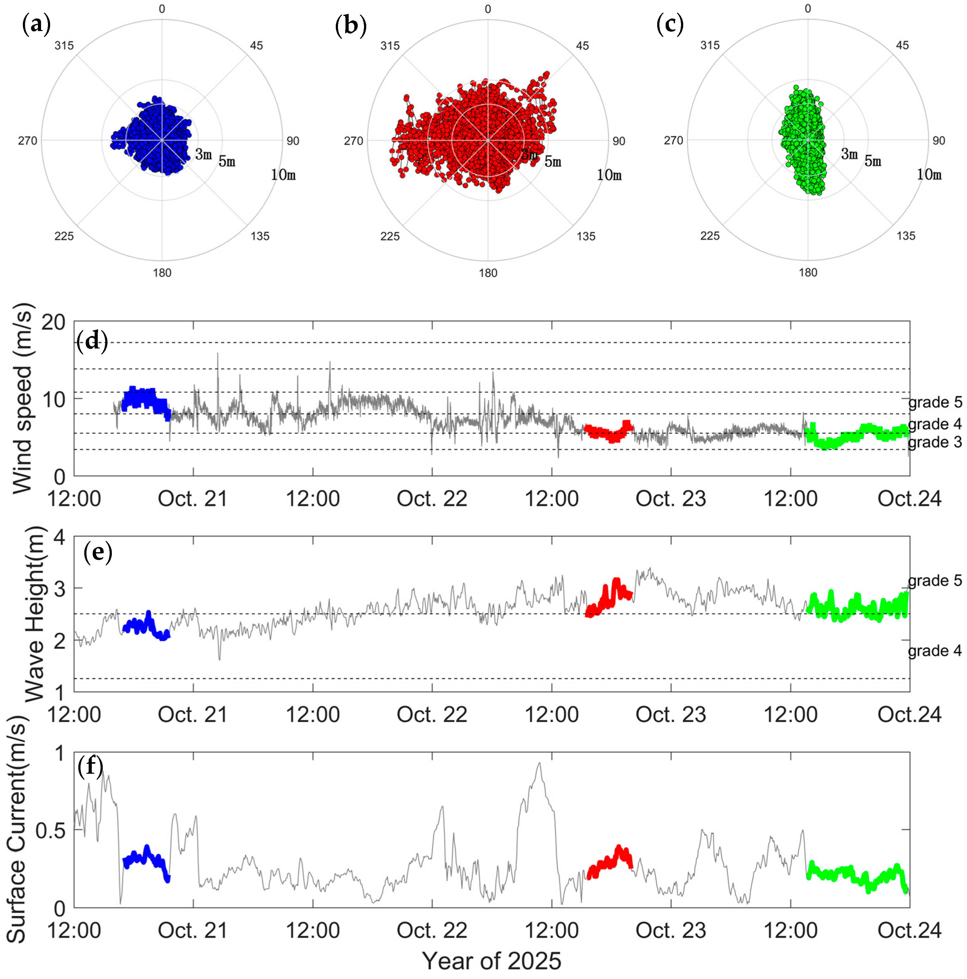
The ability of “SHIYAN 1” to maintain positioning within 3 m under sea state 4 is highly impressive among research vessels, especially given that catamarans are generally more challenging to control than monohulls. To better evaluate the performance of the upgraded dynamic positioning system, we selected data from three consecutive DP operations conducted over a three-day offshore mission for comparative analysis. As shown in Figure 8, the three time intervals are: T1 from 16:55 to 21:37 on 20 October; T2 from 15:00 to 20:15 on 22 October; and T3 from 13:35 to 23:46 on 23 October.
Figure 8a shows that all positioning points during T1 fall within a 3 m radius, with deviations distributed uniformly in all directions. In T2 (Figure 8b), 98.6% of the points are within 5 m, while 1.4% deviate between 5 and 10 m, with a maximum deviation of 8.1 m. Figure 8c indicates that all points in T3 remain within a 5 m radius, though they exhibit a strip-like distribution along the north–south direction. In terms of environmental conditions, wind speed during T1 corresponded to Force 5, while T2 and T3 experienced Force 3–4 winds. Wave height data indicate that T1 took place in sea state 4, T2 in sea state 5, and T3 in sea state 4–5. Current speed data show that surface flow velocities during all three periods were relatively low, around 0.5 knots. Through comparative analysis, it can be concluded that wave height has the most significant impact on positioning accuracy, followed by wind speed, while current speed has the least influence.

5. Conclusions

This paper presents the upgrade and application of the dynamic positioning (DP) system onboard the small waterplane area twin-hull vessel “SHIYAN 1”. By applying Euler transformations, the six-degree-of-freedom ship model is simplified into a three-degree-of-freedom model. Under combined environmental loads induced by wind, waves, and currents, a dynamically positioned vessel tends to deviate from its target position.
Sea trials were conducted under such environmental conditions using the ship equipped with three thrusters. A detailed comparison between active and inactive DP modes demonstrates that the DP system successfully maintained the vessel’s position within a 5 m radius. During the experiments, the average wind speed was 10.1 m/s, with a maximum of 13.4 m/s; the average wave height was 2.6 m, peaking at 3.2 m; and the average current velocity was 0.17 m/s, reaching up to 0.2 m/s.
By analyzing data from three separate DP positioning tests carried out between 20 and 23 October, it was found that wave load has the most significant impact on positioning accuracy, followed by wind load, while current load has the least influence. Under Force 5 winds and Sea State 5 conditions, the maximum observed DP positioning offset was 8.1 m. This represents excellent station-keeping performance for a small waterplane area catamaran, demonstrating its capability to effectively support scientific tasks such as fixed-point observation, ROV operations, and the deployment of ‘L’-shaped arrays.

Author Contributions

Conceptualization, B.W. and X.L.; methodology, Y.Q.; investigation, L.Y.; resources, C.X.; data curation, L.Y.; writing—original draft preparation, J.Y.; writing—review and editing, J.Y., K.W., Z.Q. and X.W.; visualization, H.M.; supervision, Z.W. and H.M.; funding acquisition, Z.W. All authors have read and agreed to the published version of the manuscript.

Funding

This study was funded by the Strategic Priority Research Program of the Chinese Academy of Sciences (Grant No. XDC0190101).

Data Availability Statement

The data presented in this study are available on reguest from the corresponding author. The data are nopublicly available due to privacy.

Acknowledgments

Data and samples were collected onboard the R/V SHIYAN 1. The authors extend their gratitude to the crew for their invaluable assistance during the cruise.

Conflicts of Interest

The authors declare no conflicts of interest.

References

  1. Warren, N.F. What Future for Semi-Submersible Twin-Hull Ship. Nav. Archit. 1977, 2, 53–55. [Google Scholar]
  2. Campana, E.F.; DiMascio, A.; Esposito, P.G. Domain decomposition technique for the design of twin hull ship. Hydrodyn. Theory Appl. 1996, 1–2, 59–64. [Google Scholar]
  3. Kamil, M.S.; Muslim, M.; Ali, I. Solving Wave Flow Energy Propagated by Twin-Hull Ships (Catamarans). J. Phys. Conf. Ser. 2017, 822, 012057. [Google Scholar] [CrossRef]
  4. Pirsalami, A.G.; Yousefifard, M.; Nowruzi, H. Interference effects on hydrodynamic characteristics of twin-hull ship in calm water and regular waves. Ships Offshore Struct. 2025, 1–13. [Google Scholar] [CrossRef]
  5. Ni, B.Y.; Semenov, Y.A. Impulsive impact of a twin hull. J. Fluid Mech. 2024, 983, A16. [Google Scholar] [CrossRef]
  6. Prokofiev, V.V.; Arkhangelsky, E.A.; Boyko, A.V.; Filatov, E.V. Using the Wave Propulsors in a Small-Waterplane-Area-Twin-Hull Boat. Fluid Dyn. 2023, 58, 19–30. [Google Scholar] [CrossRef]
  7. Kunugi, M.; Fujimori, K.; Nakano, T. Development of observation systems for global-scale marine pollution with persistent organic pollutants deployed on voluntary observation ships. Bunseki Kagaku 2006, 55, 835–845. [Google Scholar] [CrossRef]
  8. Dubrovsky, V.A.; Matveev, K.I. Small waterplane area ship models: Reanalysis of test results based on scale effect and form drag. Ocean Eng. 2006, 33, 950–963. [Google Scholar] [CrossRef]
  9. Davis, M.R.; Holloway, D.S. The influence of hull form on the motions of high speed vessels in head seas. Ocean Eng. 2003, 30, 2091–2115. [Google Scholar] [CrossRef]
  10. Techet, A.H. Propulsive performance of biologically inspired flapping foils at high Reynolds number. J. Exp. Biol. 2008, 211, 274–279. [Google Scholar] [CrossRef]
  11. Qian, P.; Yi, H.; Li, Y. Numerical and experimental studies on hydrodynamic performance of a small-waterplane-area-twin- hull (swath) vehicle with inclined struts. Ocean Eng. 2015, 96, 181–191. [Google Scholar] [CrossRef]
  12. Torben, T.R.; Teel, A.R.; Kjerstad, O.K.; Wittemann, E.H.T.; Skjetne, R. A Resetting Observer for Linear Time-Varying Systems With Application to Dynamic Positioning of Marine Surface Vessels. IEEE Trans. Control Syst. Technol. 2024, 32, 1048–1056. [Google Scholar] [CrossRef]
  13. Fossen, T.I. Handbook of Marine Craft Hydrodynamics and Motion Control; Wiley: Hoboken, NJ, USA, 2011. [Google Scholar]
  14. Bargoth, N.; Dalen, C.; Di Ruscio, D. Dynamic positioning, system identification and control of marine vessels. Model. Identif. Control 2022, 43, 111–117. [Google Scholar] [CrossRef]
  15. Athanasia, A.; Anne-Bénédicte, G.; Jacopo, M. The offshore wind market deployment: Forecasts for 2020, 2030 and impacts on the European supply chain development. Energy Procedia 2012, 24, 2–10. [Google Scholar] [CrossRef]
  16. Neves, K.L.S.; Dotta, R.; Malta, E.B.; Neto, A.G.; Franzini, G.R.; Bitencourt, L.A.G.B. A digital twin to predict failure probability of an FPSO hull based on corrosion models. J. Mar. Sci. Technol. 2023, 28, 862–875. [Google Scholar] [CrossRef]
  17. Mu, D.D.; Feng, Y.P.; Wang, G.F.; Fan, Y.S.; Zhao, Y.S. Single-parameter-learning-based robust adaptive control of dynamic positioning ships considering thruster system dynamics in the input saturation state. Nonlinear Dyn. 2022, 110, 395–412. [Google Scholar] [CrossRef]
  18. Li, L.; Yang, H.T.; Zhang, Y.; Ma, Q. Dynamic positioning error analysis and modeling of CNC machine tool guideway system. J. Mech. Sci. Technol. 2021, 35, 1955–1967. [Google Scholar] [CrossRef]
  19. Fossen, T.I. A survey on nonlinear ship control: From theory to practice. IFAC Proc. Vol. 2000, 33, 1–16. [Google Scholar] [CrossRef]
  20. Tannuri, E.A.; Donha, D.C.; Pesce, C.P. Dynamic positioning of a turret moored FPSO using sliding mode control. Int. J. Robust Nonlinear Control 2001, 11, 1239–1256. [Google Scholar] [CrossRef]
  21. Arditti, F.; Souza, F.L.; Martins, T.C.; Tannuri, E.A. Thrust allocation algorithm with efficiency function dependent on the azimuth angle of the actuators. Ocean Eng. 2015, 105, 206–216. [Google Scholar] [CrossRef]
  22. Ruth, E. Propulsion Control and Thrust Allocation on Marine Vessels. Ph.D. Thesis, Norwegian University of Science and Technology, Trondheim, Norway, July 2008. [Google Scholar]
  23. Balchen, J.G.; Jenssen, N.A.; Sælid, S. Dynamic positioning using Kalman filtering and optimal control theory. In Proceedings of the IFAC/IFIP Symposium on Automation in Offshore Oil Field Operation, Bergen, Norway, 14–17 June 1976; pp. 183–186. [Google Scholar]
  24. Saelid, S.; Jenssen, N.; Balchen, J. Design and analysis of a dynamic positioning system based on Kalman filtering and optimal control. IEEE Trans. Autom. Control 1983, AC-28, 331–339. [Google Scholar] [CrossRef]
  25. Grimble, M.J.; Johnson, M.A. Optimal Control and Stochastic Estimation: Theory and Applications; Wiley: Hoboken, NJ, USA, 1986. [Google Scholar]
  26. Fossen, T.I.; Sagatun, S.I.; Sørensen, A.J. Identification of dynamically positioned ships. Control Eng. Pract. 1996, 4, 369–376. [Google Scholar] [CrossRef]
  27. Tannuri, E.A.; Donha, D.C. H∞ controller design for dynamic positioning of a turret moored FPSO. IFAC Proc. Vol. 2000, 33, 263–268. [Google Scholar] [CrossRef]
  28. Perez, T.; Donaire, A. Constrained control design for dynamic positioning of marine vehicles with control allocation. Model. Identif. Control 2009, 30, 57–70. [Google Scholar] [CrossRef]
  29. Stephens, R.I.; Burnham, K.J.; Reeve, P.J. A practical approach to the design of fuzzy controllers with application to dynamic ship positioning. IFAC Proc. Vol. 1995, 28, 370–377. [Google Scholar] [CrossRef]
  30. Fossen, T.I.; Grovlen, A. Nonlinear output feedback control of dynamically positioned ships using vectorial observer backstepping. IEEE Trans. Control Syst. Technol. 1998, 6, 121–128. [Google Scholar] [CrossRef]
  31. Tannuri, E.A.; Agostinho, A.C.; Morishita, H.M.; Moratelli, L. Dynamic positioning systems: An experimental analysis of sliding mode control. Control Eng. Pract. 2010, 18, 1121–1132. [Google Scholar] [CrossRef]
  32. Hespanha, J.P.; Morse, A.S. Switching between stabilizing controllers. Automatica 2002, 38, 1905–1917. [Google Scholar] [CrossRef]
  33. Hespanha, J.P.; Liberzon, D.; Morse, A.S. Hysteresis-based switching algorithms for supervisory control of uncertain systems. Automatica 2003, 39, 263–272. [Google Scholar] [CrossRef]
  34. Sørensen, A.J.; Quek, S.T.; Nguyen, T.D. Improved operability and safety of DP vessels using hybrid control concept. In Proceedings of the International Conference on Technology & Operation of Offshore Support Vessels, Singapore, 20–21 September 2005; pp. 11–21. [Google Scholar]
  35. Nguyen, D.T.; Blanke, M.; Sørensen, A.J. Diagnosis and fault tolerant control for thruster-assisted position mooring. IFAC Proc. Vol. 2007, 40, 287–292. [Google Scholar] [CrossRef]
  36. Blanke, M.; Kinnaert, M.; Lunze, J.; Staroswiecki, M.; Schröder, J. Diagnosis and Fault-Tolerant Control; Springer: Heidelberg, Germany, 2006. [Google Scholar]
  37. Nguyen, T.D.; Sørensen, A.J.; Quek, S.T. Design of hybrid con troller for dynamic positioning from calm to extreme sea conditions. Automatica 2007, 43, 768–785. [Google Scholar] [CrossRef]
  38. Fang, S.; Blanke, M. Fault monitoring and fault recovery control for position-moored vessels. Int. J. Appl. Math. Comput. Sci. 2011, 21, 467–478. [Google Scholar] [CrossRef]
  39. Kalikatzarakis, M.; Coraddu, A.; Oneto, L.; Anguita, D. Optimizing Fuel Consumption in Thrust Allocation for Marine Dynamic Positioning Systems. IEEE Trans. Autom. Sci. Eng. 2022, 19, 122–142. [Google Scholar] [CrossRef]
  40. Fossen, T.I. A survey of control allocation methods for ships and underwater vehicles. In Proceedings of the 2006 14th Mediterranean Conference on Control and Automation, Ancona, Italy, 28–30 June 2006; pp. 1–6. [Google Scholar]
  41. Sørensen, A.J. A survey of dynamic positioning control systems. Annu. Rev. Control 2011, 35, 123–136. [Google Scholar] [CrossRef]
  42. Wynn, P. A note on the generalised Euler transformation. Comput. J. 1971, 14, 437–441. [Google Scholar] [CrossRef]
  43. IMCA. Specification for DP Capability Plots; The International Marine Contractors Association: London, UK, 2000. [Google Scholar]
  44. Akgün, M.A.; Garcelon, J.H.; Haftka, R.T. Fast exact linear and non-linear structural reanalysis and the Sherman–Morrison–Woodbury formulas. Int. J. Numer. Methods Eng. 2001, 50, 1587–1606. [Google Scholar] [CrossRef]
  45. De Kat, J.O.; Wichers, J.E.W. Behavior of a moored ship in unsteady current, wind, and waves. Mar. Technol. SNAME News 1991, 28, 251–264. [Google Scholar] [CrossRef]
  46. Faltinsen, O. Sea Loads on Ships and Offshore Structures; Cambridge Univ. Press: Cambridge, UK, 1993. [Google Scholar]
  47. He, C.D. Design of Dynamically Positioning System of Scientific Survey Ship “Ocean No. 1”. Ship Eng. 2004, 26, 2. (In Chinese) [Google Scholar]
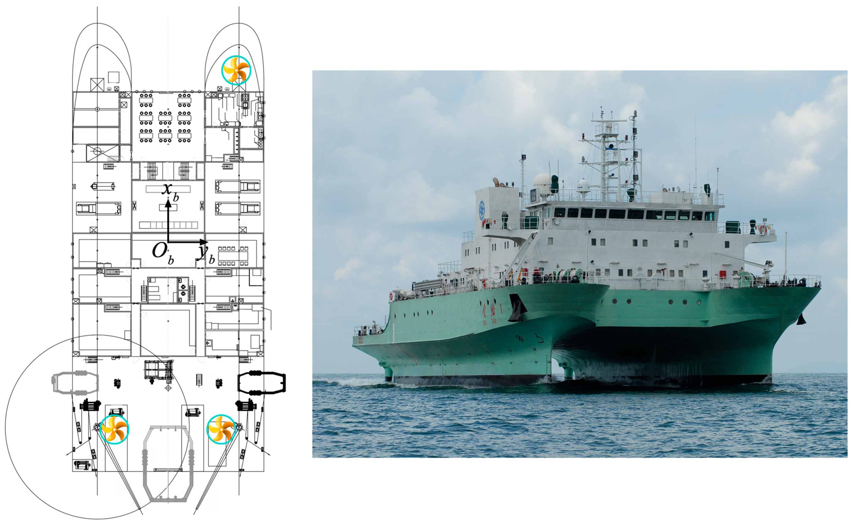
Figure 1. The layout diagram of Thruster for SHIYAN 1 and the physical image.
Jmse 13 02198 g001
Figure 2. Schematic diagram of MEGA-GUARD DP1.
Jmse 13 02198 g002
Figure 3. The vessel location distribution map. The blue line refers to the cruise tracks and the red circles refer to the positions during DP-conditions.
Jmse 13 02198 g003
Figure 4. Time series chart of pitch (up), roll (middle) and heading (down), with red indicating the presence of DP and blue indicating the absence of DP.
Jmse 13 02198 g004
Figure 5. Time series chart of wind speed (up) and direction (down), with red indicating the presence of DP and blue indicating the absence of DP.
Jmse 13 02198 g005
Figure 6. Time series chart of wave height (up) and direction (down), with red indicating the presence of DP and blue indicating the absence of DP.
Jmse 13 02198 g006
Figure 7. Time series chart of current speed (up) and direction (down), with red indicating the presence of DP and blue indicating the absence of DP.
Jmse 13 02198 g007
Figure 8. Maps (ac) show the positions of ships conducting DP operations during three time periods. (d) The wind speed values, (e) the wave height values, and (f) the surface flow velocity values. Blue, red, and green represent three time periods, respectively.
Jmse 13 02198 g008
Table 1. Main parameters of the R/V SHIYAN 1.
MainTotal Length60.9 m
ParametersBreadth26 m
Depth10.5 m
Draft6.5 m
Gross Tonnage3071
Net Tonnage921
Maximum Speed15 knots
Endurance8000 n miles
Sustainability40 days
Capacity72
Ship TypeSWATH
PowertrainMain Propulsion1700 kW × 2
Bow Thruster440 kW
Generator Set1600 kw × 3 + 380 kW
Disclaimer/Publisher’s Note: The statements, opinions and data contained in all publications are solely those of the individual author(s) and contributor(s) and not of MDPI and/or the editor(s). MDPI and/or the editor(s) disclaim responsibility for any injury to people or property resulting from any ideas, methods, instructions or products referred to in the content.