Article

Investigation of the Internal Solitary Wave Influence on Subsea Equipment Lowering with a Continuous Lowering Analysis Model

1
School of Energy and Mechanics, Dezhou University, Dezhou 253023, China
2
Beijing National Innovation Institute of Lightweight Ltd., Beijing 100086, China
3
Collge of Ocean Science and Engineering, Shanghai Maritime University, Shanghai 201306, China
*
Author to whom correspondence should be addressed.
J. Mar. Sci. Eng. 2025, 13(11), 2177; https://doi.org/10.3390/jmse13112177
Submission received: 21 October 2025 / Revised: 13 November 2025 / Accepted: 15 November 2025 / Published: 17 November 2025
(This article belongs to the Section Ocean Engineering)

Abstract

Deep-water payload lowering operations are highly sensitive to hydrodynamic disturbances, particularly to internal solitary waves (ISWs) that are frequently observed in the South China Sea and other stratified shelf regions. This study develops a two-dimensional lumped-mass cable-payload model to investigate the dynamic responses of a lowering system subjected to combined excitations of vessel heave, uniform background current, and ISW-induced velocity shear. With the variable-domain technique, the model incorporates variable boundary conditions through element activation, Morison-type hydrodynamic loading, and a simplified but physically consistent mode-1 ISW kinematic representation based on an extended KdV formulation with vertical modal decay. Numerical implementation is achieved using an explicit central-difference scheme with initialization through static equilibrium and ramped velocity conditions. Parametric simulations are performed to examine the coupled influence of ISW peak velocity, heave amplitude, and lowering speed on cable tension and lateral displacement. Results indicate that ISWs can significantly amplify dynamic loads. The continuous lowering analysis model provides a valuable tool for subsea equipment lowering simulation. And the findings provide quantitative evidence of ISW-induced risks in deep-water lowering.

1. Introduction

Lowering heavy subsea equipment is a reliability-critical operation in ocean engineering. The dynamic interaction among the deployment line, payload, and surrounding hydrodynamic environment can significantly amplify line tension and induce slack-snap events, threatening operational safety. The lowering process is inherently non-stationary because both the excitation and system characteristics change continuously with cable payout [1,2]. Field observations and laboratory experiments further demonstrate that extreme responses typically occur during splash-zone crossing and early immersion, where added mass, damping, and coupling with crane motion vary rapidly [3,4,5]. Consequently, a continuous analysis method capable of representing both cable payout and cross-flow effects is required for reliable prediction of dynamic responses during deployment and retrieval.
Recent advances in modeling techniques have largely converged on two main time-domain approaches: lumped-mass (LM) and finite-element (FE) formulations. These frameworks can incorporate variable-length strategies to represent continuous cable payout, often referred to as variable-domain or element-activation techniques. Around the splash zone, Zan et al. [6,7] and Guo et al. [8] combined RANS or experiments and SIMO-type tools to quantify sling/cable tensions under regular and irregular seas, providing validation targets for system models. At a reduced order, Tommasini et al. [9] showed that KC-dependent hydrodynamic coefficients shift natural frequency and peak tensions in nonlinear single-DOF lowering models. Gao et al. [10] proposed a continuous-lowering LM formulation that incorporates structural damping, nonlinear drag, and snap-load logic while activating elements as the line pays out. Other variable-length cable problems, such as deployment systems with turning or retrieval, further confirm the practicality of the element-activation approach and the effectiveness of static-to-dynamic handshakes, supported by sea-trial validations [11,12,13,14]. Parallel studies on active heave compensation (AHC) systems highlight the importance of tension management and motion isolation; Kim and Ku [15] reviewed passive and active options. Xie et al. [16] analyzed electric-winch AHC control under irregular waves. And Chen et al. [17] conducted model-scale AHC experiments for offshore cranes.
In stratified oceans, internal solitary waves (ISWs) represent another critical source of hydrodynamic disturbance. These nonlinear internal waves generate vertically sheared subsurface currents that may equal or exceed surface forcing at depth. Extensive observations in the South China Sea reveal frequent and energetic ISW events, with improved forecasting capabilities now available near operational hotspots [18,19,20,21]. Laboratory and numerical studies have shown that ISWs can markedly increase the motions and mooring tensions of floating structures and modify the dynamic response envelopes of slender members, such as risers and suspended bodies, through depth-dependent shear [22,23,24,25]. These findings imply that lowering operations, which inherently traverse the ISW field as the cable length changes, are subject to dynamic disturbances that cannot be captured by models considering only surface waves or uniform currents.
Despite significant advances in both lowering and ISW modeling, few studies have coupled a variable-length two-dimensional cable-payload model with a time-varying, horizontally sheared ISW current to quantify its impact on tension, trajectory control, and slack-snap risk. Addressing this gap, the present study develops a two-dimensional lumped-mass variable-domain model that incorporates both uniform background current and idealized ISW kinematics. The approach enables realistic simulation of the full lowering process under combined excitations, providing insights into ISW-induced risks for subsea operations.

2. Methodology

2.1. Governing Equations

The cable-payload system is subjected to environmental loads and the surface vessel motion. In this Section, the combined environmental excitations, including vessel heave, background current, and ISW-induced shear, are coupled together. And the kinetic equations of the cable and payload are deduced. However, it has to be noted that no hydrodynamic feedback from the cable-payload system to the flow field is considered, i.e., the current and wave field is prescribed and unaffected by the structure.

2.1.1. Kinetic Equations

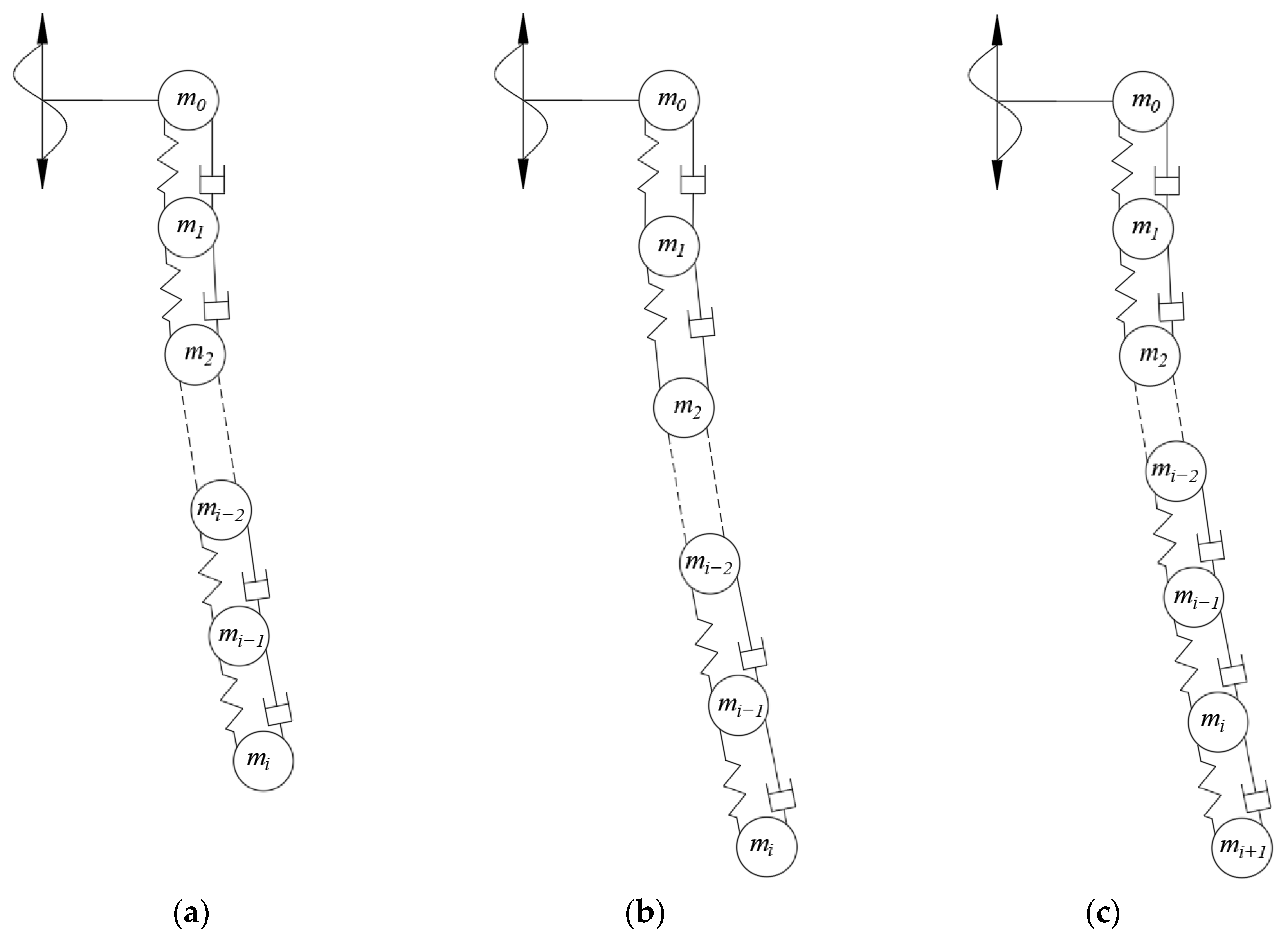
The deep-water lowering operation is modeled as a coupled cable-payload system in the vertical plane, as illustrated in Figure 1. The payload is lifted by the lowering cable and subjected to its weight, buoyancy and hydrodynamic loads. For a payload with dry mass m p , its governing equation of motion could be expressed as:
M p r ¨ p = T p τ p + ( 0 , m p g ρ w V p g ) + 1 2 ρ w C D , p A p ( x ) x ˙ p U x x ˙ p U x , 1 2 ρ w C D , p A p ( z ) z ˙ p z ˙ p ,
where M p = d i a g m p + m a x , m p + m a z ; m a is its added mass; r p is the position vector of payload; T p is the line traction at the payload; τ p is the tangential vector of cable at the payload; g is the grvatitional acceleration; ρ w is the water density; C D , p is the drag coefficient on payloda; A p ( x ) and A p ( z ) are the projected area on the x and z direction, respectively; x p and z p are the coordinates on the x and z direction, respectively; and U x is the current velocity on the x direction.
As shown in Figure 1a, the cable is idealized as an extensible, tension-only string in the (x, z) plane with arc-length s 0 , L ( t ) . For a point on the cable, its position is r s ,   t   =   ( x ( s ,   t ) ,   z ( s ,   t ) ) . Let λ = r / s , the axial extension e = λ 1 , and e ˙ = λ / t . The momentum balance per unit length is given by:
ρ l 2 r t 2 = s T τ + f w b + f D ,   τ = s r s r ,
with a tension-only elastic-viscous law:
T = m a x 0 , E A e + c e ˙ ,   k = E A l 0 ,   c = 2 ζ k ρ r l 0 .
where ρ l is the line mass of the cable; f w b and f D are the weight-bouyance and drag force vectors, respectively; E A is the axial stiffness of the cable; l 0 is the initial length of the cable; c is the damping factor; and ζ is the axial damping coefficient of the cable.

2.1.2. External Loads

The distributed loads on the cables combine weight, buoyancy and hydrodynamic force. As the weight and buoyancy acts in the z direction, the net weight in water is expressed as:
f w b = 0 , ρ w A c ρ r g .
in which A c is the cross-sectional area of cable.
The hydrodynamic force is calculated with the Morison equation. Let n be the in-plane unit normal to the cable (rotate τ by +90°), i.e., n = τ z , τ x . In the normal direction, the DNV moving-member Morison load per unit length is expressed as
f N = ρ w C M A a n ρ w C A A r ¨ n + 1 2 ρ w C D , c D w n w n ,
in which C M is the inertia coefficient; C A is the added mass coefficient; and the relative current velocity is calculated with
r ¨ n = r ¨ · n ,
w n = w · n ,   w = U r ˙ .
where U is the current velocity vector.
The total water particle velocity and acceleration applied in the load calculation should be obtained by summing the contributions from the background current and the ISW-induced flow field. Surface waves are not directly included in the fluid kinematic fields due to their limited zone of influence. Instead, their effect is accounted for by applying the resulting motion of the top-side floating body as a boundary condition.
In this study, motion of the top-connected floating unit is simplified as a sinusoidal heave motion. Therefore, the top boundary of the cable is prescribed with the heave motion as Equation (8).
z ( 0 , t ) = A s s i n 2 π t / T s .
where A s is the heave amplitude, and T s is the heave period.
To avoid oscillation at the beginning of simulation, the payout rate of cable L ˙ ( t ) follows a raised-cosine ramp into constant payout V t in the time range of [0, T r ] as Equation (9).
L ˙ ( t ) = 1 2 V t 1 c o s π t / T r , 0 t T r V t , t > T r .

2.1.3. Internal Solitary Wave

The scale of internal solitary waves is orders of magnitude larger than that of marine structures, such as pipelines and cables. Consequently, the perturbation these structures introduce to the internal solitary wave field is negligible. Therefore, the governing equations of the cable structure incorporated the internal solitary wave field through a one-way coupling scheme, i.e., the ISW velocity and acceleration fields are prescribed kinematic inputs incorporated into the hydrodynamic load calculation.
In continuously stratified oceans, a two-layer ISW approximation is often insufficient. To capture vertical shear effects, a mode-1 extended Korteweg–de Vries (eKdV) framework is adopted. For an inviscid, incompressible, and Boussinesq fluid on an plane, the background density profile ρ 0 z is prescribed, leading to a buoyancy frequency N 2 ( z )   = ( g / ρ 0 )   d ρ 0 / d z . The buoyancy frequency determines the wave’s vertical structure, which is obtained by solving the Sturm–Liouville eigenvalue problem for the vertical mode shape Φ ( z ) and linear long-wave speed c 0 , as formulated in Equation (10).
d d z 1 N 2 ( z ) d Φ d z + 1 c o 2 Φ ( z ) = 0 , H z 0 .
There exists several models describing the horizontal evolution of internal solutions, such as the Benjamin–Ono (BO) equation [26] and the extended-KdV (eKdV) equation. Compared to the BO equation, the eKdV equation naturally accommodates both quadratic and cubic nonlinear terms, which are important when the stratification or amplitude is moderate to large [27]. And its coefficients can be expressed directly in terms of the mode-1 eigenfunction for continuous stratification and hence are convenient for modal-based loading reconstructions. In contrast, the BO model is most appropriate in the physical scaling where the lower layer can be approximated as infinitely deep. Therefore, horizontal evolution of the wave amplitude η ( x , t ) at a reference depth is governed by the following equation:
η t + c 0 η x + α η η x + β η 2 η x + γ 3 η x 3 = 0 ,
in which, the coefficients α , β , γ can be derived from the vertical mode, ensuring consistency with the stratification.
The coefficients c 0 , α , β , γ appearing in Equation (10) are obtained from the mode-1 eigenfunction Φ ( z ) and the buoyancy frequency Λ ( z ) via standard modal integrals. In compact form,
c 0 = H 0 Λ 2 z Φ z d z H 0 Φ z d z   ,
and the nonlinear and dispersive coefficients α , β , γ are given by weighted integrals involving Φ ( z ) and its derivatives. Grimshaw et al. (2002) and Apel et al. (2003) gave their exact forms and implementation [28,29].
Considering the actual depth-dependent horizontal velocity for solitary waves [30,31], the modal-reconstruction approach is adopted in this study to reconstruct the flow velocity field for computational efficiency. Following the standard modal-decomposition theory for internal waves [28,29], the leading-order vertical structure is represented by the mode-1 eigenfunction Φ ( z ) . Given the wave amplitude η ( x , t ) , horizontal and vertical particle velocities u and w are computed as follows:
u ( x , z , t ) = U ( x , t ) Φ ( z ) ,                   U ( x , t ) = C η ( x , t ) ,
w ( x , z , t ) = C 1 k η x ( x , t ) d Φ d z ( z ) ,
in which, C is a modal-to-velocity scaling factor chosen such that the horizontal particle velocity at the pycnocline equals the prescribed peak ISW horizontal velocity used in simulations, and k is an effective horizontal wavenumber scale. Acceleration in the x direction is calculated as,
u t ( x , z , t ) = C Φ ( z ) η t ( x , t ) .
Equation (10) admits solitary-wave solutions in the absence of forcing, and that interactions between solitary waves and external forcing have been studied in the literature [32]. However, to retain computational efficiency, we prescribe the amplitude envelope rather than solving the forced amplitude equation dynamically. The kinematic prescription uses a traveling solitary envelope consistent with such solutions, as Equation (16).
S ( ξ ) = s e c h 2 p ( ξ / Δ ) , ξ = x x 0 c s t ,
in which Δ = F W H M / 1.763 (FWHM is the full width at half maximum), and p is an exponent (default p = 1 gives s e c h 2 shape).
The vertical modal shape Φ(z) is approximated by a smooth antisymmetric profile centered at the pycnocline z c :
Φ ( z ) = tanh ( z z c H c / 2 ) ,
Φ ( z ) = 1 ( H c / 2 ) s e c h 2 ( z z c H c / 2 ) .
This surrogate mimics a normalized mode-1 eigenfunction and is very cheap numerically. Below the pycnocline center z c , the surrogate optionally applies an exponential decay:
Φ d e c ( z ) = Φ ( z ) , z z c , Φ ( z ) exp ( ( z z c ) / L d ) , z < z c .
Therefore, the disturbance becomes negligible in depths far below the pycnocline depth. And the water particle velocities are formulated as follows.
u ( x , z , t ) = U p k Φ d e c ( z ) s e c h 2 p ( ( x x 0 c s t ) / Δ ) ,
w ( x , z , t ) = α w U p k Φ d e c ( z ) s e c h 2 p ( ( x x 0 c s t ) / Δ ) .
where U p k is the peak ISW horizontal velocity near the pycnocline.
In general, Equations (13)–(21) describe an approximate reconstructions based on a modal amplitude equation and an analytic surrogate for the vertical mode shape of the ISW field. They are not exact solutions of the full inviscid Euler equations. Nevertheless, they capture the leading-order modal shear and amplitude structure relevant to load calculations for lowering operations in mode-1-dominated stratified fields.

2.2. Lumped-Mass Disretization

As shown in Figure 1b, with the lumped-mass method, the cable is discretized into N axial segments connecting nodes i = 0 , . . . , N . The unknown free nodal displacement vectors q is,
q = x z = x 0 , . . . , x N 1 , x p , z 0 , . . . , z N 1 , z p T R 2 N , v = q ˙ , a = q ¨ .
The set of the governing equations for N nodes is organized as,
M ( q ) v ˙ = F i n t ( q , v ) + F e x t ( q , v , t ) ,
in which the general mass matrix is M ( q ) = b l c k d i a g M x , M z , where M x = d i a g m s e g , . . . , m s e g , m s e g + m p + m a x and M z = d i a g m s e g , . . . , m s e g , m s e g + m p + m a z ; and the force vectors are F i n t ( q , v ) = [ F x i n t ; F z i n t ] and F e x t ( q , v , t ) = F x g b + F x M + F x p ; F z g b + F z M + F z p . For the Node 0, its nodal displacement is prescribed by the boundary motion.

2.2.1. Internal Force

To calculate the internal and external forces on the nodes, the basic vectors defined on elements are expressed as follows using boundary-augmented vectors x b = [ x 0 ; x ] , z b = [ z 0 ; z ] .
x = G x b ,   z = G z b ,
L = x 2 + z 2 ,
τ x = x L , τ z = z L ,
n x = τ z , n z = τ x ,
e = L l 0 I , s ˙ = G x ˙ b τ x + G z ˙ b τ z ,
where G R N × ( N + 1 ) is the forward difference operator, which converts parameters from nodes to segments.
The elementwise tension is expressed as
T = m a x 0 , k e + c s ˙ .
The internal nodal forces is then deduced as
F x , i i n t = T i τ x , i T i + 1 τ x , i + 1 ,
F z , i i n t = T i τ z , i T i + 1 τ z , i + 1 .

2.2.2. External Force

The external loads on the cable are first calculated per segment and then mapped to the nodes. For the discretized cable, the segment-average kinematics are defined as
v ¯ x , i = 1 2 x ˙ b , i 1 + x ˙ b , i ,   v ¯ z , i = 1 2 z ˙ b , i 1 + z ˙ b , i ,
a ¯ x , i = 1 2 x ¨ b , i + x ¨ b , i + 1 ,   a ¯ z , i = 1 2 z ¨ b , i + z ¨ b , i + 1 .
The relative background flow velocity is defined on segments, and projected on the normal direction to the cable as
w x = U x v ¯ x ,   w z = U z v ¯ z ,
w n = w x n x + w z n z ,
a f , n = a f , x n x + a f , z n z .
And the cable segment acceleration in its normal direction is
r ¨ n = a ¯ x n x + a z ¯ n z .
The per-segment normal Morison load per unit length external is expressed as
f N = ρ w C M A a f , n ρ w C A A r ¨ n + 1 2 ρ w C D , c D w n w n ,
and vectorized segment forces are
f M , x = f N n x ,
f M , z = f N n z .
Along with the gravity and buoyancy, those forces are mapped to the nodes with Equations (42)–(44).
F x M = A t f M , x ,
F z M = A t f M , z ,
F z g b = A t ρ w A c ρ r g l 0 I ,
F x g b = 0 .
where A t = A a v g T is the mapping operator, which maps segment loads to nodes.
The external forces on the payload are also mapped to the Nth node on the cable. By moving the inertia hydrodynamic force acting on the payload to the LHS of the governing equation, the external force acting on the payload is mapped to the nodes as
F x p = e N f x , N p = e N 1 2 ρ w C D , p A p ( x ) x ˙ N U x , N x ˙ N U x , N ,
F z p = e N f z , N p = e N 1 2 ρ w C D , p A p ( z ) z ˙ N z ˙ N .
in which e N is a vector representing the payload position in the overall force vector.

2.3. Numerical Solution Algorithm with Variable Domain

The equation set is solved with an explicit time integration with central difference. The time marching scheme is as follows,
a n = M ( q n ) 1 F i n t ( q n , v n ) + F e x t ( q n , v n , t n ) ,
v n + 1 2 = v n 1 2 + a n t ,
q n + 1 = q n + v n + 1 2 t .
A conservative stability step time increment is determined with Equation (50).
t α ρ r l 0 2 E A , α 0.25,0.35
To minimize the numerical oscillation at the beginning, a static initialization is conducted by computing a nonlinear equilibrium at L 0 with steady background, using dynamic relaxation until nodal residuals are below tolerance.
The cable length varies as the payload is lowered or recovered. To tackle with the variable length of cable, a variable-domain technique is proposed, as shown in Figure 2. In the lowering process, it maintains the segment length l 0 d L m a x , which is a maximum length for a segment. When L t / d L m a x exceeds the active segment count N, activate a new segment and reparametrize states by arc-length to avoid impulses with the following procedures.
(1)
Build cumulative arc-length σ 0 , L o l d along the old polyline, and form continuous maps r o l d σ , r ˙ o l d σ
(2)
Generate new nodes: σ j n e w = j L n e w / N n e w , j = 0 , . . . , N n e w .
(3)
Conduct position and velocity interpolation: r j n e w = r o l d σ j n e w L o l d / L n e w , r ˙ j n e w = r o l d ˙ σ j n e w L o l d / L n e w .
(4)
Recompute l 0 , e i , e ˙ i , and enforce T i = m a x 0 , E A e i + c e ˙ i .

2.4. Model Validation

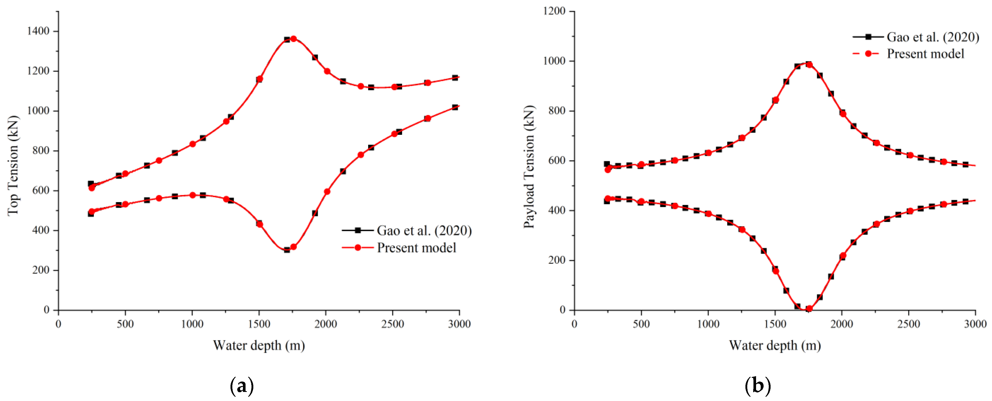
The model proposed in this study could be degraded to the 1D model proposed in [10]. The basic parameters of the simulation cases in this study are listed in Table 1. For the payload lowered with a speed of 0.3 m/s, the tensions at the top and lower end of cable are compared between the two models, as shown in Figure 3. As the tension inside the cable oscillates during the lowering process due to the top heave motion, the envelope of tension is plotted. It is evident that the present model agrees well with the model proposed in [10].
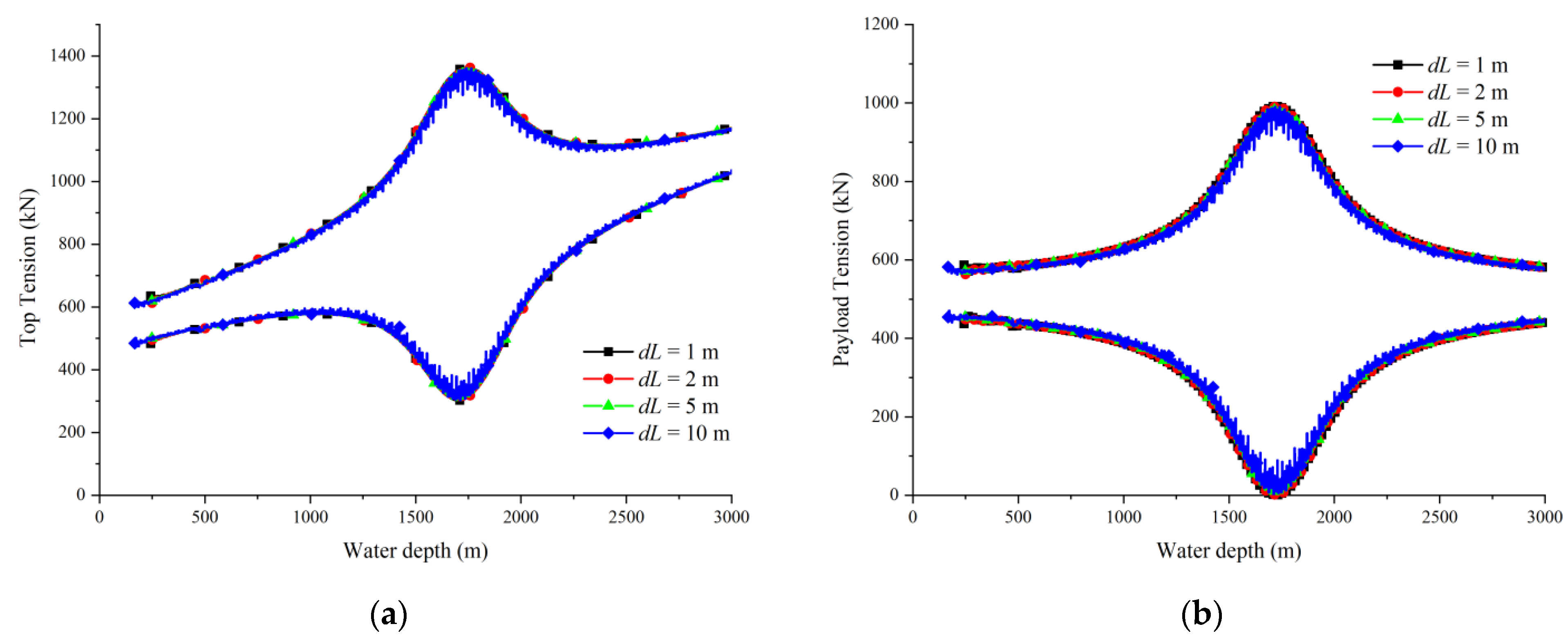
The present model is easy to implement, as it is simple and straight. However, its sensitivity to the segment length is investigated to find an economic length. Four cases with segment lengths of 1 m, 2 m, 5 m and 10 m are simulated and compared. As shown in Figure 4, the cable deflection is not sensitive to the segment length, a coarse size of 10 m can give good prediction. As shown in Figure 5, the segment length of 5 m is fine enough for a good prediction of the top and lower end tension. However, the segment length of 10 m gives about 2% underestimation of the tension.

3. Results and Discussion

The proposed model enables coupled simulation of the lowering process under combined effects of internal solitary waves, background currents, vessel heave, and variable payout. This Section examines how these factors influence cable tension and lateral displacement of the payload. Unless otherwise specified, the system parameters are listed in Table 1.

3.1. Effect of Cross Flow

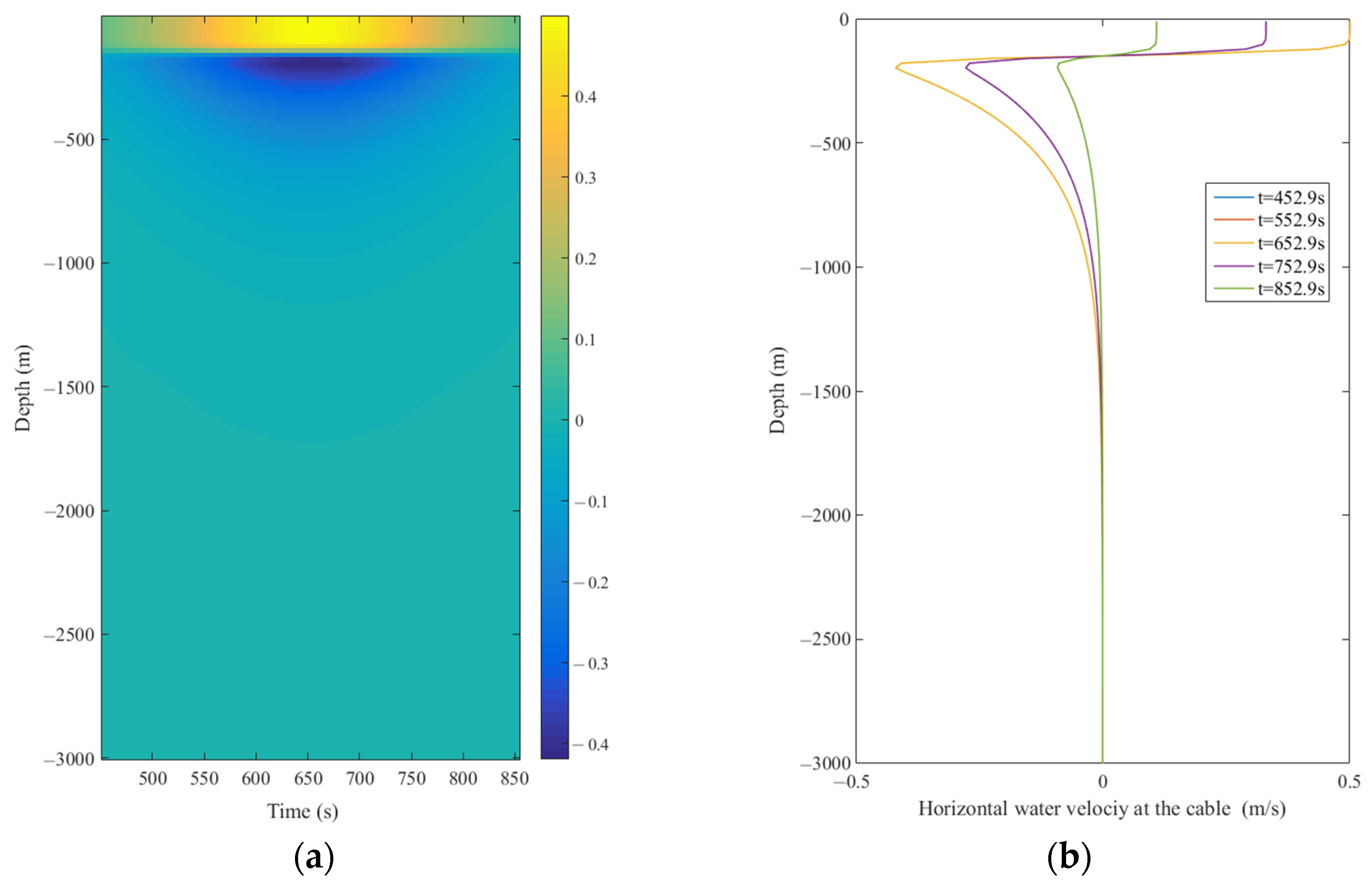
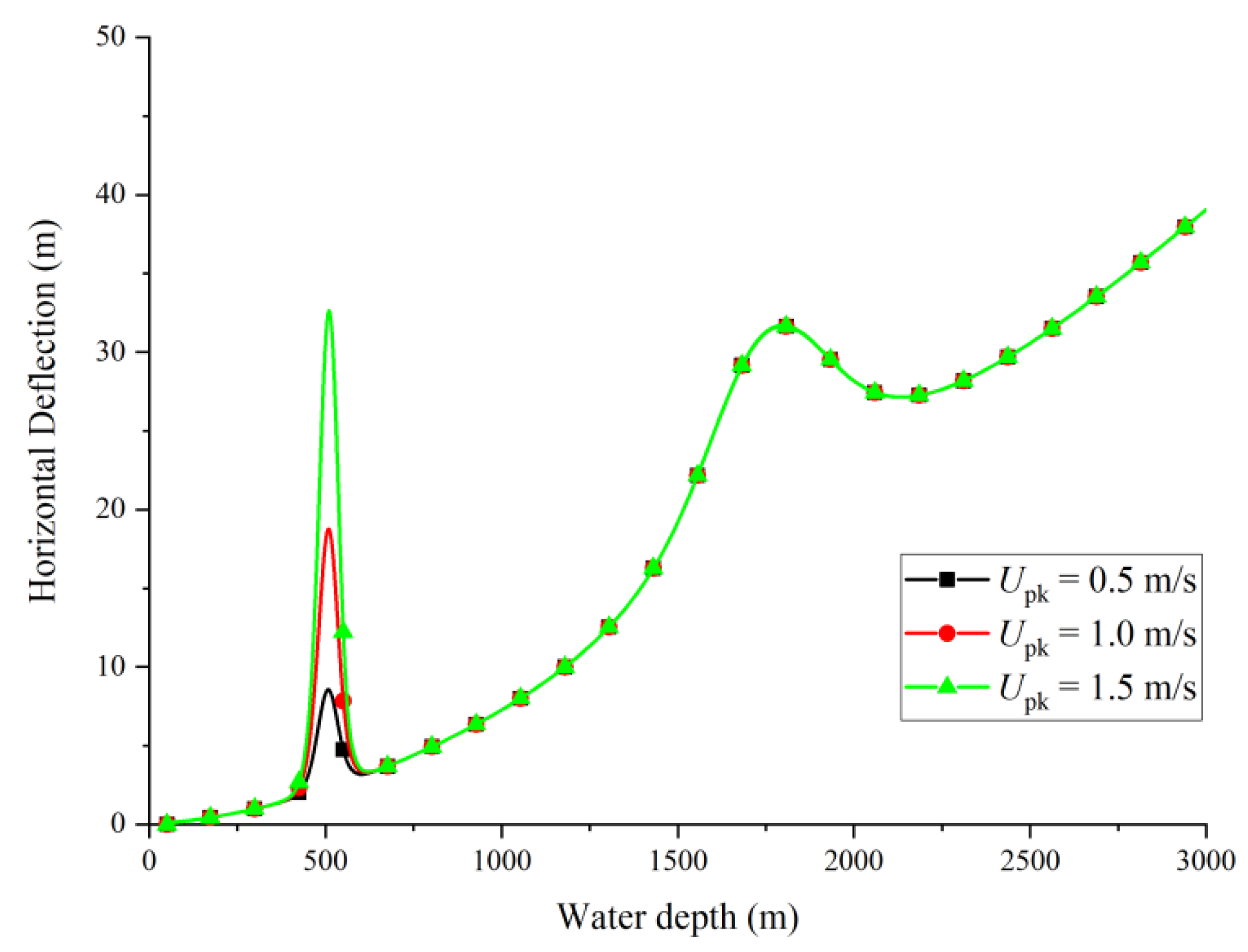
Both the ocean current and ISW can cause the cable and payload to have a significant lateral displacement in the lowering process. Three cases were simulated under the action of ISWs with peak horizontal velocities of 0.5 m/s, 1.0 m/s and 1.5 m/s. Other ISW parameters are listed in Table 2, and the background current velocity is 0.5 m/s. With those parameters, the ISW velocity filed for a peak horizontal velocity U p k = 0.5 m/s is plotted in Figure 6a. And the water particle velocity profile along the water depth at different times are plotted in Figure 6b. It is shown that the water particle velocity reverses at the pycnocline.
In those cases, the ISW crest reaches the cable when the payload is lowered to the water depth of 500 m. The horizontal deflections at the lower end of the cable, e.g., the horizontal payload displacement, are compared in Figure 7. It is shown that the ISW significantly increases the horizontal payload displacement. And the horizontal deflection also significantly increases when the cable-payload system reaches its resonance zone. When the payload dive through the pycnocline, the horizontal displacements are amplified to 8.57 m, 18.78 m and 32.65 m, respectively.
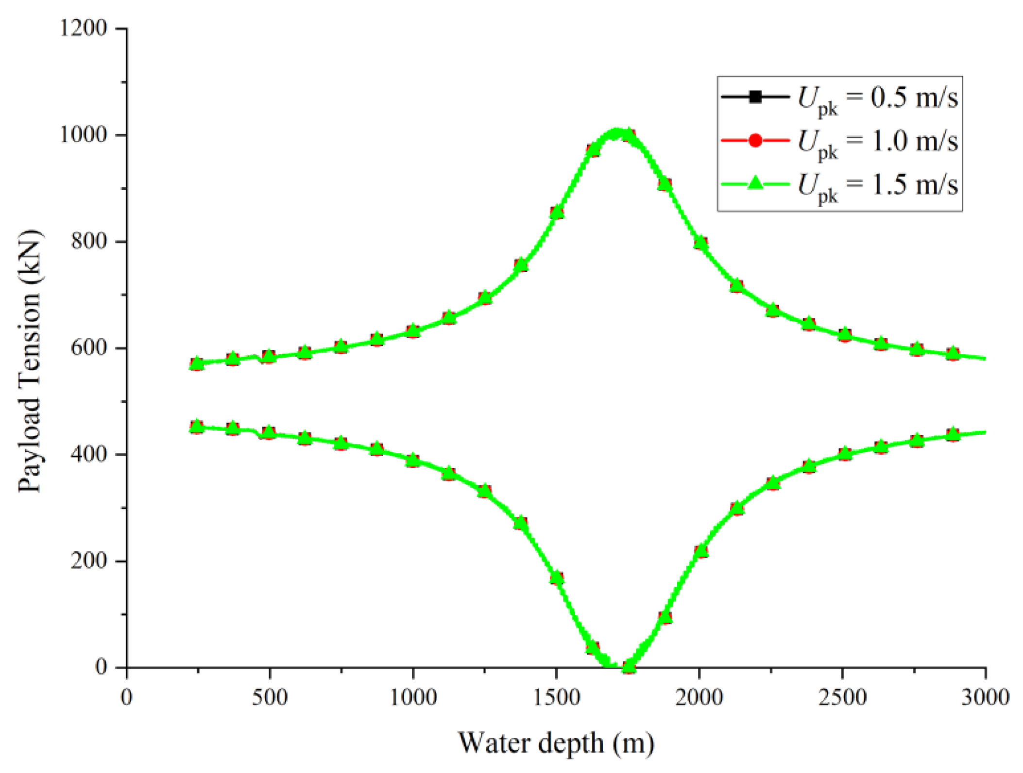
In contrast, as shown in Figure 8, the ISW effect on the payload tension is relatively modest. This limited impact arises because the ISW-induced velocity shear is confined near the pycnocline, whereas the lower portions of the cable and payload experience diminished flow intensity with depth. Thus, ISWs mainly alter the lateral trajectory rather than the vertical load state.
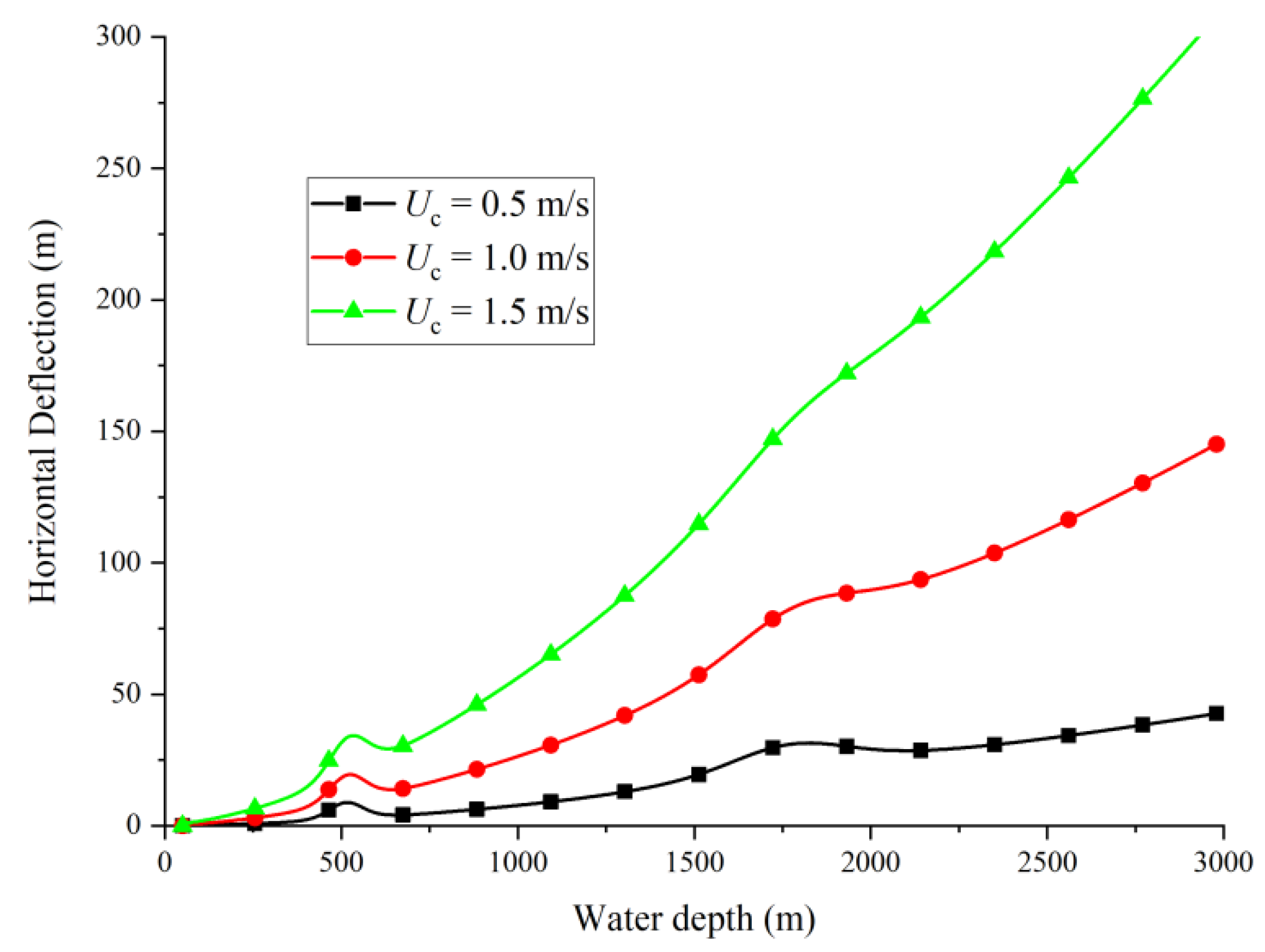
To distinguish ISW-induced effects from steady current influences, additional simulations were performed under uniform background currents of 0.5 m/s, 1.0 m/s, and 1.5 m/s. As shown in Figure 9, the current has significant effects on the cable deflection, which is obvious as the current is the main factor causing horizontal deflection. As shown in Figure 10, the current also has a significant effect on the cable tension, especially in the resonance region, which is different from the ISW. This is attributed to the horizontal cable deflection, which introduces a component of the horizontal force exerted by ocean currents on both the cable and the payload along the cable’s axis.

3.2. Effect of Lowering Velocity

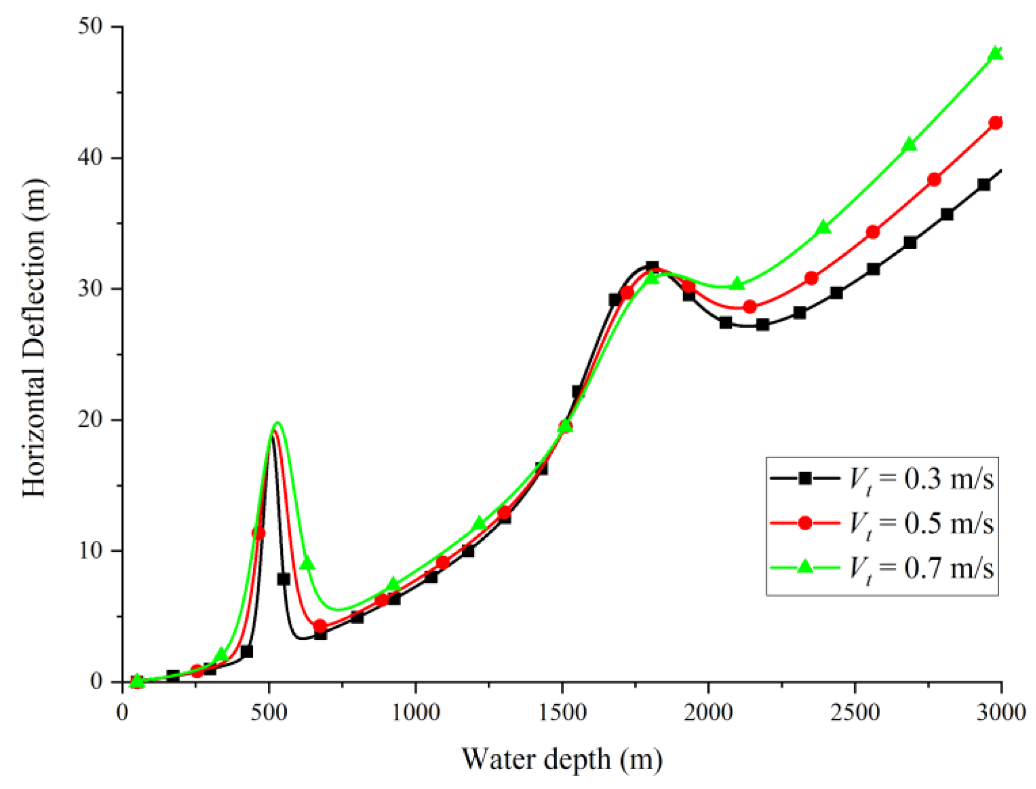
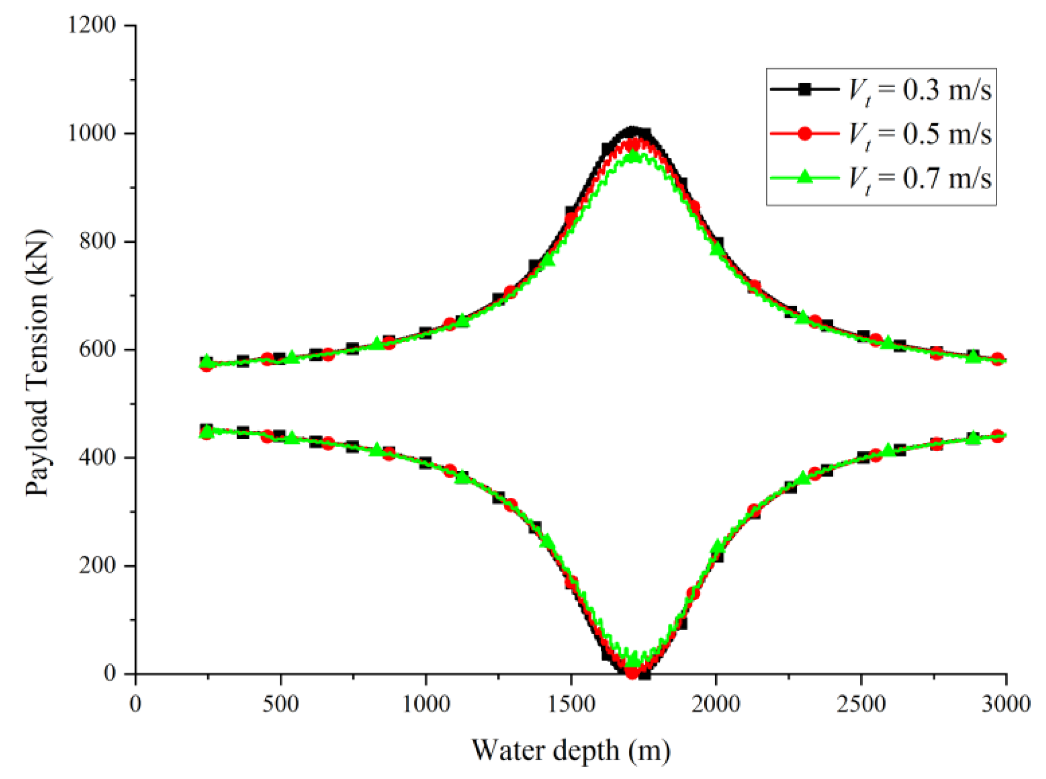
The influence of the cable payout speed was analyzed through three cases with lowering velocities of 0.3 m/s, 0.5 m/s, and 0.7 m/s. The horizontal payload displacements at the lower end are shown in Figure 11. It is indicated that the lowering velocity has significant effects on the horizontal cable deflection, especially in deep water depth. This occurs because the increased downward motion enhances the vertical hydrodynamic force acting on the payload, which is slightly inclined due to lateral offset, thereby generating an additional horizontal component that promotes deflection growth.
As shown in Figure 12, variations in lowering velocity have a relatively small effect on the mean cable tension, since the vertical hydrodynamic load remains small compared to the payload’s immersed weight. However, localized tension fluctuations are amplified near the resonance region, where coupled oscillations between the payload and cable system occur. These results indicate that while lowering velocity weakly influences average tension, it can still affect dynamic amplification near resonant conditions, and thus should be considered in operation planning.

3.3. Effect of Top Heave

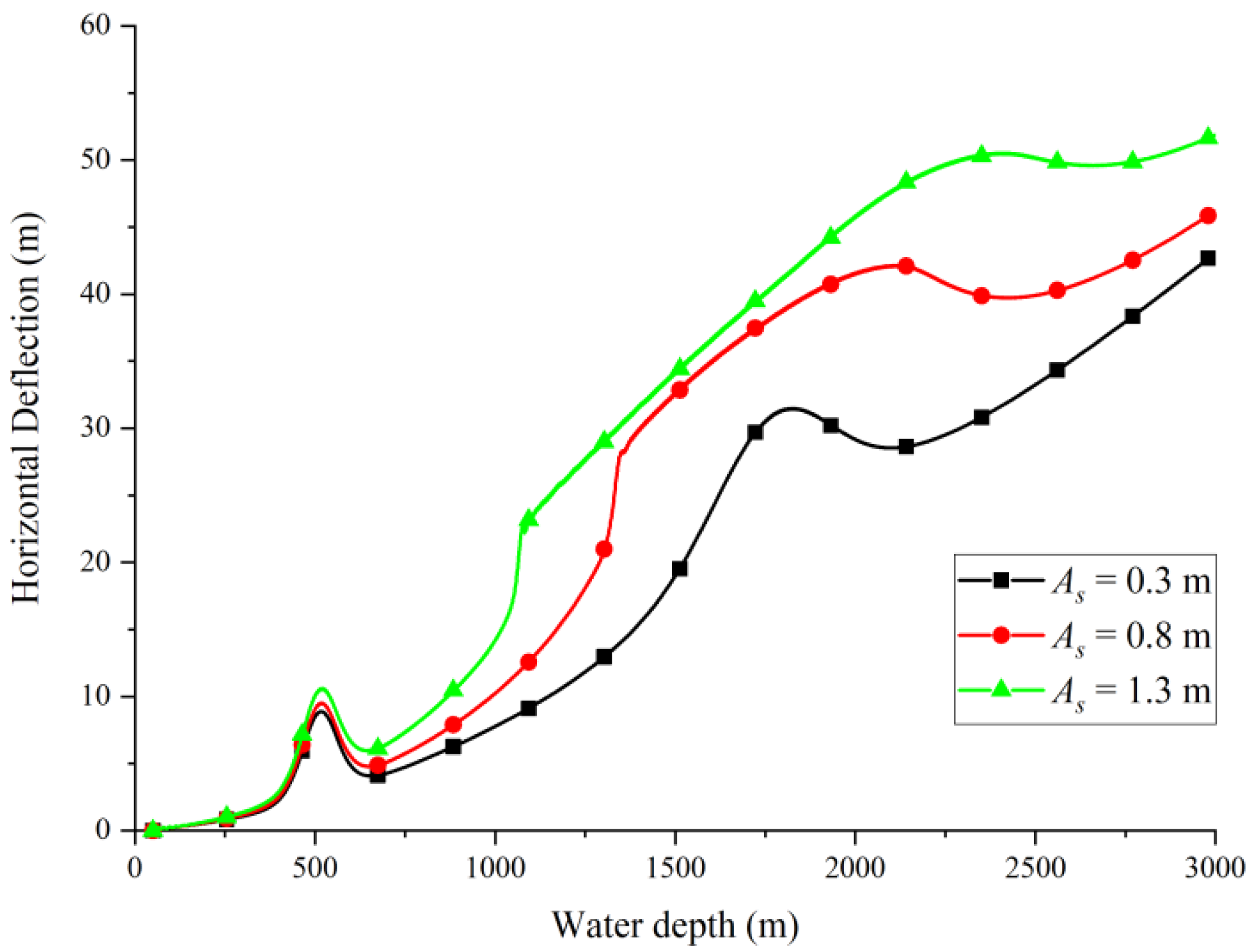
Vessel heave introduces a moving upper boundary that strongly influences the dynamic response of the lowering system. To quantify this effect, three heave amplitudes of 0.3 m, 0.8 m and 1.3 m were considered, all with a period of 9 s. As shown in Figure 13, larger heave amplitudes result in substantially greater lateral motion of the payload. The dynamic coupling between the vertical vessel motion and cable geometry increases with heave amplitude, producing greater horizontal excursions even in moderate currents.
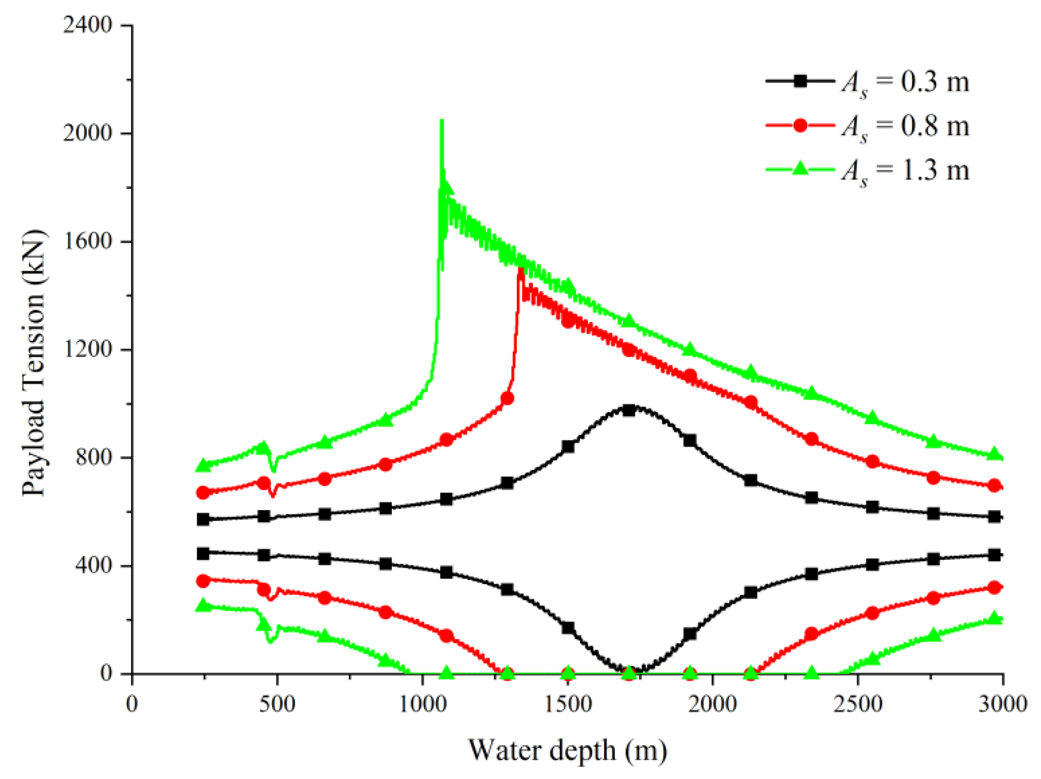
The tension responses in Figure 14 reveal that high-amplitude heave motion can induce slack-snap behavior. In cases with amplitudes of 0.8 m and 1.3 m, the tension momentarily drops to near zero and then spikes sharply as the cable re-tensions, indicating snap loads. These tension peaks pose significant risks to cable integrity and lifting safety. The results clearly demonstrate that vessel heave is the dominant factor governing extreme tension events, far more critical than ISW or lowering velocity effects.
The occurrence of snap loads underscores the necessity of active heave compensation (AHC). An effective AHC system can mitigate vertical motion transmission, preventing both slack and excessive tension peaks. The present simulations suggest that snap loads emerge when heave amplitude exceeds approximately 0.3 m for the modeled system parameters, which provides a useful operational threshold for design and safety assessments.

4. Conclusions

A two-dimensional lumped-mass numerical model has been established to study the dynamics of deep-water payload lowering in the presence of internal solitary waves. The model accounts for variable geometry through element activation, Morison-type hydrodynamic forces, and a computationally efficient mode-1 ISW velocity field.
The simulation results demonstrate that ISWs primarily influence the lateral displacement of the cable-payload system, with the magnitude of deflection increasing as ISW peak velocity rises. While the effect of ISWs on payload tension is limited due to their localized influence in depth, and background currents significantly contribute to both lateral displacement and tension amplification. Lowering velocity was found to affect payload deflection more strongly in deep water, though its impact on tension remained relatively small except near resonance regions. Vessel heave motions were shown to be a dominant factor in generating snap loads, highlighting the critical need for active heave compensation to ensure safe operations.
The proposed continuous lowering model offers a practical tool for engineering assessment of offshore operations in stratified oceans. Although the present study simplifies certain physical processes, such as more sophisticated ISW modes and active heave compensation, the approach provides a tractable framework for engineering evaluation. Future work should focus on incorporating site-specific stratification profiles and integrating active heave compensation to support safe and efficient offshore lowering operations.

Author Contributions

Conceptualization, P.G. and M.L.; methodology, M.L.; software, G.C.; validation, J.Z. and G.C.; investigation, M.L.; data curation, J.Z.; writing—original draft preparation, M.L.; writing—review and editing, P.G.; visualization, M.H.; funding acquisition, M.L. All authors have read and agreed to the published version of the manuscript.

Funding

This research was funded by Technology Innovation Center for Carbon Sequestration and Geological Energy Storage, Ministry of Natural Resources, grant number MNRCCUS062301.

Data Availability Statement

The original contributions presented in this study are included in the article. Further inquiries can be directed to the corresponding author.

Conflicts of Interest

Author Guosong Chen was employed by the company Beijing National Innovation Institute of Lightweight Ltd. The remaining authors declare that the research was conducted in the absence of any commercial or financial relationships that could be construed as a potential conflict of interest.

Nomenclature

The following symbols are used in this manuscript:
SymbolDescriptionUnit
( x , z )Horizontal and vertical coordinates in 2D planem
s Arc length along the cablem
q Nodal displacement vector of lumped-mass modelm
N Number of active segments in the cable
L Suspended cable lengthm
l e Element (segment) lengthm
ρ l Linear mass density of cablekg/m
m p Dry mass of the payloadkg
m a Added mass of the payloadkg
E A Axial stiffness of cable N
ζ Axial damping coefficient of cableN·s/m
τ Tangential unit vector of cable segment
n Normal unit vector of cable segment
T Cable tensionN
g Gravitational accelerationm/s2
C D , c Drag coefficient on the cable
C D , p Drag coefficient on the payloadm
ρ w Seawater densitykg/m3
u Horizontal water particle velocity m/s
w Vertical water particle velocitym/s
u r Relative fluid velocity (structure vs. current)m/s
η ISW interface displacement m
Φ Vertical modal function of ISW
c 0 Linear long-wave phase speedm/s
C Modal-to-velocity scaling factor
c s Dispersion coefficient in eKdV
Δ ISW half-widthm
U p k Peak ISW horizontal velocitym/s
A s Amplitude of surface heavem
T s Period of surface heaves
V t Lowering (payout) speed of cablem/s
δ Pycnocline thicknessm
H Total water depthm

References

  1. de Andrade, E.M.; de Oliveira Costa, D.; Fernandes, A.C.; Sales Junior, J.S. A Review on the Modeling of Subsea Lifting Operations. Ocean Eng. 2023, 275, 113293. [Google Scholar] [CrossRef]
  2. Tommasini, R.B.; Pavanello, R.; de Oliveira Carvalho, L. Prediction of Design Loads for Deep Water Subsea Lifting Operations Based on Non-Stationary Time Response. Mar. Struct. 2020, 74, 102818. [Google Scholar] [CrossRef]
  3. Li, L.; Parra, C.; Zhu, X.; Ong, M.C. Splash Zone Lowering Analysis of a Large Subsea Spool Piece. Mar. Struct. 2020, 70, 102664. [Google Scholar] [CrossRef]
  4. Wang, Y.; Yang, C.; Yang, Z.; Zhao, X.; Yin, J.; Hu, Y. Dynamic Analysis of a Subsea Suspended Manifold Going through Splash-Zone During Installation. China Ocean Eng. 2022, 36, 553–564. [Google Scholar] [CrossRef]
  5. Amer, A.M.; Li, L.; Zhu, X. Dynamic Analysis of Splash-Zone Crossing Operation for a Subsea Template. Sust. Mar. Struct. 2022, 4, 18–39. [Google Scholar] [CrossRef]
  6. Zan, Y.; Guo, R.; Xue, Y.; Bai, X.; Liu, P.; Huang, F. Experimental and Numerical Investigations of Regular Head Wave Effects on Cable Tension of a Subsea Module during Lowering Operations. Ocean Eng. 2021, 239, 109822. [Google Scholar] [CrossRef]
  7. Zan, Y.; Guo, R.; Li, F.; Liu, P.; Huang, F.; Tian, L. Splash-Zone Dynamic Analysis of a Suspended Semi-Submerged Subsea Module for Irregular Waves. China Ocean Eng. 2023, 37, 258–271. [Google Scholar] [CrossRef]
  8. Guo, R.; Zan, Y.; Han, D.; Wang, Y.; Yuan, L.; Qi, B. Irregular-Wave Impact on Lowering of a Subsea Module with Large Cavity Shells. Ocean Eng. 2023, 271, 113743. [Google Scholar] [CrossRef]
  9. Tommasini, R.B.; Hill, T.L.; Macdonald, J.H.G.; Pavanello, R.; de Oliveira Carvalho, L. Nonlinear Dynamics of Deep Water Subsea Lifting Operations Considering KC-Dependent Hydrodynamic Coefficients. Ocean Eng. 2021, 233, 109172. [Google Scholar] [CrossRef]
  10. Gao, P.; Yan, K.; Ni, M.; Fu, X.; Liu, Z. A Dynamic Model for Continuous Lowering Analysis of Deep-Sea Equipment, Based on the Lumped-Mass Method. Appl. Sci. 2020, 10, 3177. [Google Scholar] [CrossRef]
  11. Zhang, D.; Zhao, B.; Zhu, K.; Jiang, H. Dynamic Analysis of Towed Cable with Variable Length during Turning Maneuvers. Sci. Rep. 2023, 13, 3525. [Google Scholar] [CrossRef] [PubMed]
  12. Zhao, Y.; Li, G.; Lian, L. Numerical Model of Towed Cable-Body System Validation from Sea-Trial Data. Ocean Eng. 2021, 226, 108859. [Google Scholar] [CrossRef]
  13. Liu, Q.; Bao, J.; Shao, Y.; Zheng, L.; Xu, H. Dynamic Modeling and Underwater Configuration Analysis of fiber optic cable for UUV-launched UAV. Ocean Eng. 2024, 303, 117774. [Google Scholar] [CrossRef]
  14. Yang, S.; Ren, H.; Zhu, X. Dynamic Modeling of Cable Deployment/Retrieval Based on ALE-ANCF and adaptive step-size integrator. Ocean Eng. 2024, 309, 118517. [Google Scholar] [CrossRef]
  15. Kim, D.; Ku, N. Heave Compensation Dynamics for Offshore Drilling Operation. J. Mar. Sci. Eng. 2021, 9, 965. [Google Scholar] [CrossRef]
  16. Xie, T.; Huang, L.; Guo, Y.; Ou, Y. Modeling and Simulation Analysis of Active Heave Compensation Control System for Electric-Driven Marine Winch under Excitation of Irregular Waves. Meas. Control 2023, 56, 1004–1015. [Google Scholar] [CrossRef]
  17. Chen, S.; Xie, P.; Liao, J.; Huang, Z. Model Experimental Studies on Active Heave Compensation Control Strategy for Electric-Driven Offshore Cranes. Ocean Eng. 2024, 311, 118987. [Google Scholar] [CrossRef]
  18. Alford, M.H.; Peacock, T.; MacKinnon, J.A.; Nash, J.D.; Buijsman, M.C.; Centurioni, L.R.; Chao, S.-Y.; Chang, M.-H.; Farmer, D.M.; Fringer, O.B.; et al. The Formation and Fate of Internal Waves in the South China Sea. Nature 2015, 521, 65–69. [Google Scholar] [CrossRef]
  19. Huang, X.; Chen, Z.; Zhao, W.; Zhang, Z.; Zhou, C.; Yang, Q.; Tian, J. An Extreme Internal Solitary Wave Event Observed in the Northern South China Sea. Sci. Rep. 2016, 6, 30041. [Google Scholar] [CrossRef]
  20. Chen, L.; Zheng, Q.; Xiong, X.; Yuan, Y.; Xie, H.; Guo, Y.; Yu, L.; Yun, S. Dynamic and Statistical Features of Internal Solitary Waves on the Continental Slope in the Northern South China Sea Derived from Mooring Observations. J. Geophys. Res. Ocean. 2019, 124, 4078–4097. [Google Scholar] [CrossRef]
  21. Gong, Y.; Chen, X.; Xu, J.; Xie, J.; Chen, Z.; He, Y.; Cai, S. An Internal Solitary Wave Forecasting Model in the Northern South China Sea (ISWFM-NSCS). Geosci. Model Dev. 2023, 16, 2851–2872. [Google Scholar] [CrossRef]
  22. Cui, J.; Dong, S.; Wang, Z.; Han, X.; Yu, M. Experimental Research on Internal Solitary Waves Interacting with Moored Floating Structures. Mar. Struct. 2019, 67, 102641. [Google Scholar] [CrossRef]
  23. Cheng, S.; Yu, Y.; Li, Z.; Huang, Z.; Yang, Z.; Zhang, X.; Cui, Y.; Wu, J.; Liu, X.; Yu, J. The Influence of Internal Solitary Wave on Semi-Submersible Platform System Including Mooring Line Failure. Ocean Eng. 2022, 258, 111604. [Google Scholar] [CrossRef]
  24. Ruan, W.; Chen, M.; Nie, Q.; Xu, P.; Li, J.; Wang, X. Dynamic Response of Steel Lazy Wave Riser Considering the Excitation of Internal Solitary Wave and Ocean Currents. Ocean Eng. 2024, 294, 116708. [Google Scholar] [CrossRef]
  25. He, Z.; Wu, W.; Wang, J.; Ding, L.; Chang, Q.; Huang, Y. Investigations into Motion Responses of Suspended Submersible in Internal Solitary Wave Field. J. Mar. Sci. Eng. 2024, 12, 596. [Google Scholar] [CrossRef]
  26. Flamarion, M.V.; Pelinovsky, E. Evolution and Statistical Analysis of Internal Random Wave Fields within the Benjamin–Ono Equation. J. Mar. Sci. Eng. 2023, 11, 1853. [Google Scholar] [CrossRef]
  27. Helfrich, K.R.; Ostrovsky, L. Effects of rotation and topography on internal solitary waves governed by the rotating Gardner equation, Nonlin. Process. Geophys. 2022, 29, 207–218. [Google Scholar] [CrossRef]
  28. Grimshaw, R.; Pelinovsky, E.; Poloukhina, O. Higher-order Korteweg-de Vries models for internal solitary waves in a stratified shear flow with a free surface, Nonlin. Process. Geophys. 2002, 9, 221–235. [Google Scholar] [CrossRef]
  29. Apel, J.R. A new analytical model for internal solitons in the ocean. J. Phys. Oceanogr. 2003, 33, 2247–2269. [Google Scholar] [CrossRef]
  30. Vlasenko, V.; Brandt, P.; Rubino, A. Structure of large-amplitude internal solitary waves. J. Phys. Oceanogr. 2000, 30, 2172–2185. [Google Scholar] [CrossRef]
  31. Grue, J. Generation, Propagation, and Breaking of Internal Solitary Waves. Chaos 2005, 15, 037110. [Google Scholar] [CrossRef] [PubMed]
  32. Flamarion, M.V.; Pelinovsky, E. Solitary Wave Interactions with an External Periodic Force: The Extended Korteweg-de Vries Framework. Mathematics 2022, 10, 4538. [Google Scholar] [CrossRef]
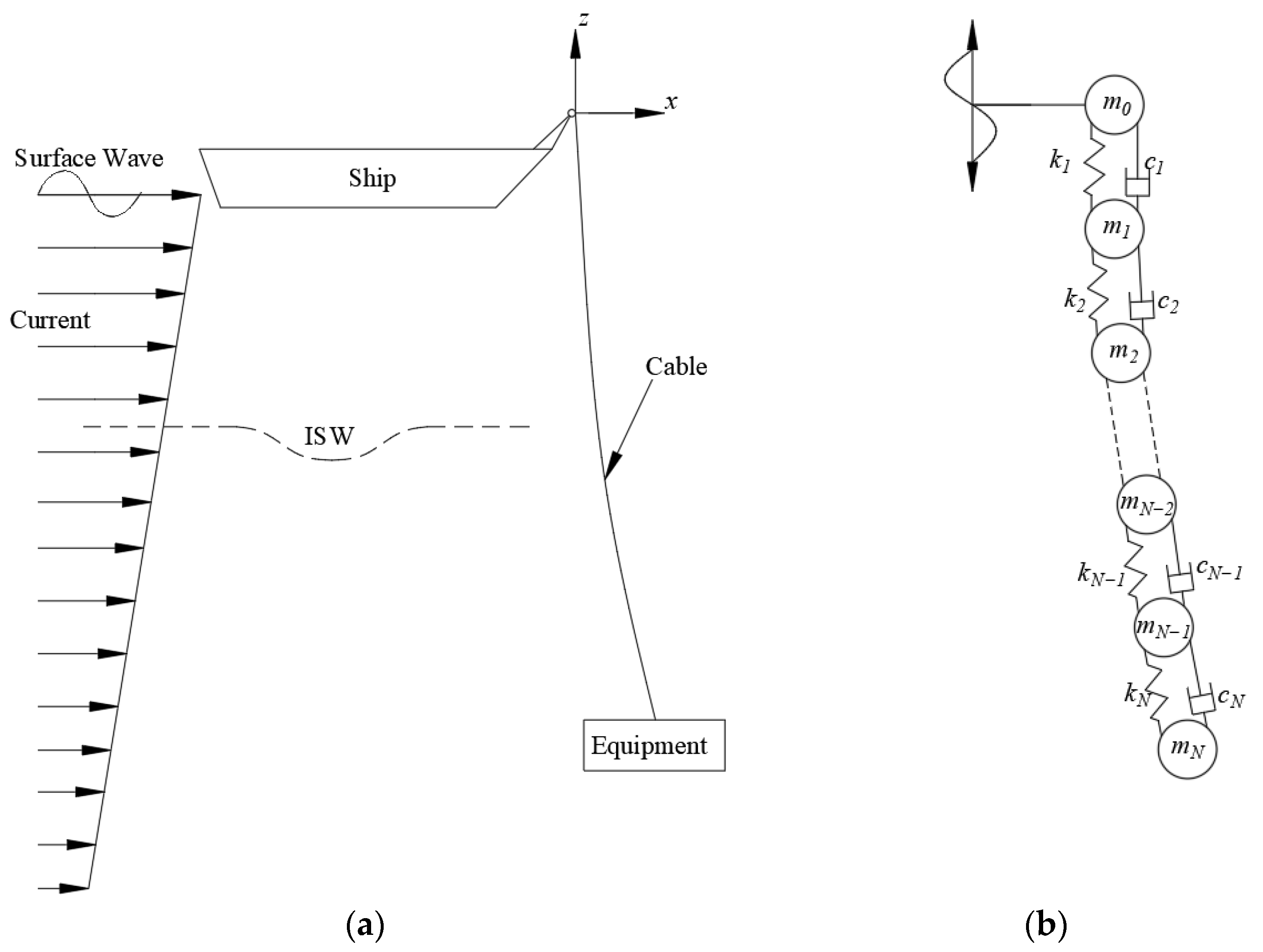
Figure 1. Schematic diagram of the continuous lowering analysis model. (a) sketch of subsea equipment lowering; (b) lumped-mass model.
Jmse 13 02177 g001
Figure 2. Schematic diagram of the variant domain technique for continuous lowering analysis. (a) initial configuration; (b) segment length adjusted; (c) additional segment added.
Jmse 13 02177 g002
Figure 3. Comparison between the present model and Gao et al. (2020) [10]: (a) tension at the top end; (b) tension at the lower end.
Jmse 13 02177 g003
Figure 4. Development of horizontal cable deflection at the lower end with different segment lengths.
Jmse 13 02177 g004
Figure 5. Development of cable tension with different segment lengths: (a) tension at the top end; (b) tension at the lower end.
Jmse 13 02177 g005
Figure 6. Development of the ISW induced water particle velocity field: (a) velocity contour; (b) velocity profile along the water depth.
Jmse 13 02177 g006
Figure 7. Development of horizontal cable deflection at the lower end with different ISW peak velocities.
Jmse 13 02177 g007
Figure 8. Development of cable tension at the lower end with different ISW peak velocities.
Jmse 13 02177 g008
Figure 9. Development of horizontal cable deflection at the lower end with different ocean current velocities.
Jmse 13 02177 g009
Figure 10. Development of cable tension at the lower end with different ocean current velocities.
Jmse 13 02177 g010
Figure 11. Development of horizontal cable deflection at the lower end with different lowering velocities.
Jmse 13 02177 g011
Figure 12. Development of cable tension at the lower end with different lowering velocities.
Jmse 13 02177 g012
Figure 13. Development of horizontal cable deflection at the lower end with different top heave amplitudes.
Jmse 13 02177 g013
Figure 14. Development of cable tension at the lower end with different top heave amplitudes.
Jmse 13 02177 g014
Table 1. System parameters for the model validation and analysis.
ParameterValue
Cable Line   mass ,   ρ l 24.6 kg/m
Cross-section   area ,   A c 4098 mm2
Axial   stiffness   product ,   E A 325 MN
Equivalent   diameter ,   D r 72.23 mm
Drag   coefficient ,   C d , r 0.7
Damping   ratio ,   ζ 0.1
Equipment Payload   mass ,   m p 60 t
Volume ,   V p 7.63 m3
Vertical   projected   area ,   A p , z 56.95 m2
Horizontal   projected   area ,   A p , x 56.95 m2
Added   mass ,   m a 300 ton
Drag   coefficient ,   C d , p 0.1
Table 2. Parameters of the internal solitary wave.
ParameterValue
Peak ISW horizontal velocity, U p k 0.5, 1.0, 1.5 m/s
Interface thickness, H c 40 m
Wave speed, c 1.5 m/s
Pycnocline depth, z c −150 m
Influenced depth in the lower layer, L d 300 m
Full Width at Half Maximum, F W H M 600 m
Disclaimer/Publisher’s Note: The statements, opinions and data contained in all publications are solely those of the individual author(s) and contributor(s) and not of MDPI and/or the editor(s). MDPI and/or the editor(s) disclaim responsibility for any injury to people or property resulting from any ideas, methods, instructions or products referred to in the content.