Article

Experimental Study on Three-Degree-of-Freedom Ventilated Cavities for Underwater Vehicles Considering the Air Mass near the Tube

1
College of Mechanical and Electrical Engineering, Harbin Engineering University, Harbin 150001, China
2
Innovation Center for Cross-Media Aircraft Technology, Harbin 150001, China
3
College of Shipbuilding Engineering, Harbin Engineering University, Harbin 150001, China
*
Author to whom correspondence should be addressed.
J. Mar. Sci. Eng. 2025, 13(11), 2111; https://doi.org/10.3390/jmse13112111
Submission received: 16 October 2025 / Revised: 3 November 2025 / Accepted: 5 November 2025 / Published: 6 November 2025
(This article belongs to the Section Ocean Engineering)

Abstract

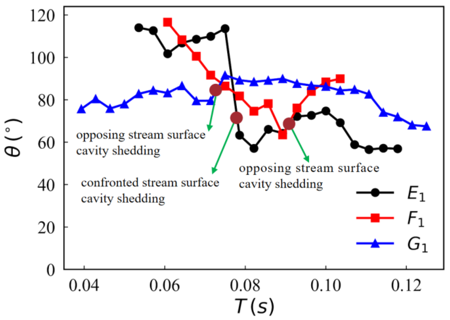
A small-scale three-degree-of-freedom decompression launch experiment method is used to study the flow characteristics in a ventilated cavity at different transverse velocities. The study subjects are three typical head-shaped underwater vehicles: hemispherical, ellipsoidal, and conical. The evolution mechanism of the ventilated shoulder cavity in a vehicle under transverse velocity is investigated, and the effects of transverse velocity and vehicle head shape changes on the cavity are summarized. Research results show that the hemispherical-headed vehicle’s ventilated cavity is prone to cavity pre-positioning, thereby affecting the distribution of the confronted stream surface (CSS) cavity. As the transverse velocity increases, the cavity pre-positioning point disappears, and the degree of deflection in the vehicle’s trajectory increases. The difference between the opposing stream surface (OSS) and the CSS cavities decreases as the cavities shed. The drag effect of the shedding air mass causes a change in the cavity closure angle. At high transverse velocity (vt = 0.6 m/s), the cavity difference between the OSS and CSS of the ellipsoidal vehicle is the largest, and the amount of gas shed at the cavity’s end is the smallest. The initial angle of the closure angle at the cavity end is related to the ability of the air mass near the tube (AMNT) to be drawn in by the head shape of the vehicle. Under the influence of transverse velocity, the shedding cavity deflects toward the OSS. The interaction patterns between the shoulder and tail cavities on vehicles with different head shapes primarily include three modes.

1. Introduction

During actual cross-medium operations of the vehicle, platform movement, the flow field changes, and the launch angle [1,2,3] directly influence the vehicle’s motion attitude and trajectory, thereby altering the flow characteristics of the vehicle’s attached cavity [4,5,6]. To reduce the impact of attitude angle variations on the hydrodynamic characteristics of the underwater vehicle, cavities are placed within the vehicle [7,8]. By wrapping the vehicle surface with ventilated cavities, the drag experienced by the vehicle during underwater operation at angles of attack is minimized. The research found that the transverse displacement at the moment of underwater vehicle exit from the water decreased by approximately 45.2%, and the deflection angle decreased by approximately 55.6% [9]. The reduction in drag experienced by the vehicle during motion effectively enhances its operational efficiency [10,11,12].
When the direction of the incoming flow is the same as the direction of gravity, spherical microbubbles are shed from the end of the bubble. However, when the direction differs from gravity, the frequency of bubble shedding at the rear varies [13]. When a vehicle departs from the free surface at a specific angle, the range and peak of cavitation collapse pressure rapidly decrease. In particular, cavitation separation and collapse behavior at the initial moment on the pressure side may lead to larger pressure peaks. At larger attitude angles, the vortex legs of the wall-mounted hairpin vortices become significantly elongated. Moreover, the direction of transverse motion similarly affects the pressure distribution and trajectory characteristics of continuously launched vehicles [14,15,16]. As the angle of exit for the water decreases, the negative peak drag coefficient decreases while the peak transverse force coefficient increases [17]. As the attitude angle increases, the pressure distribution of the vehicle becomes more uniform and regular, while the transverse side may experience disturbance spread and transition toward turbulence [18]. Under high angle-of-attack conditions, vortex generators arranged along the underwater vehicle significantly reduce crossflow separation on the vehicle [19]. The transverse flow velocity affects the corresponding relationship between complex fluids and the launch tube structure. At the same time, the transverse flow alters the attitude and motion state of the vehicle [20]. In the water tunnel experiments, researchers have conducted much work on the effects of angle of attack on the cavities of vehicles and have drawn several conclusions. The angle of attack significantly influences the flow field structure of the ventilated bubbles. As the attack angle increases, the ventilated cavity asymmetry becomes more significant, and the angle between the body axis and the closure line decreases [21]. The opaque gas–liquid mixture region gradually focuses along the counterflow surface as the transparent bubble region on the counterflow surface increases [22]. For the vehicles with attitude angles, the upstream cavity of the vented tail cavity is steadier and longer, making it more prone to re-entrant flow closure [23].
The cavity dimensions and flow patterns have a strong dependence on the shape of the vehicle’s head [24,25]. When the vehicle is out of the launch tube, the flow field at its shoulder undergoes complex interactions with the air mass near the tube and the mixed medium, significantly affecting changes in the cavity and flow field [26]. The curvature of the vehicle’s head affects the flow pattern around its shoulders. Compared to the smoothly transitioning head shape, the high-curvature head shape is more prone to forming natural cavitation in the low-pressure zone of the vehicle’s shoulder, exhibiting a stronger ability to entrain the air mass near the tube [27]. The conical-headed vehicle exhibits superior anti-interference capabilities and more stable ballistics compared to the elliptical-headed vehicle [28]. Compared to conical- and disk-shaped cavitators, parabolic cavitators reduce resistance more effectively for a wider range of cavitation numbers [29].
In summary, research on the effects of transverse velocity on the cavities attached to a vehicle remains insufficient. Currently, research on the effects of transverse velocity on vehicles primarily focuses on the end cavity, with a particular lack of experimental studies on the three-degree-of-freedom ventilated shoulder cavity. The primary research methods for ventilated cavities involve numerical simulation, water tunnel experiments, or drag-in-water tests. Due to experimental constraints, studies on three-degree-of-freedom ventilated cavities in ejection tests remain limited. At the same time, the effect of the vehicle’s head shape on the ventilated cavity during three-degree-of-freedom motion remains unclear and requires further investigation. Experimental studies on the effect of transverse velocity on the ventilated cavity under decompression conditions and the interaction between shoulder and tail cavities are even more scarce. Research on achieving three-degree-of-freedom ventilated cavities for the vehicle under decompression conditions represents a technical breakthrough in small-scale experiments. The head shape is a key factor determining the flow pattern in the ventilated shoulder cavity, and its influence on the shoulder cavity cannot be overlooked. Based on small-scale three-degree-of-freedom decompression experiments, the flow patterns in the cavity of three head types (hemispherical, ellipsoidal, and conical) are discussed at different transverse velocities, considering the influence of (AMNT). The interaction relationship between the shoulder and tail cavities is studied to provide reference for cross-medium experimental studies on the motion of three-degree-of-freedom underwater vehicles.

2. Experimental Setup

2.1. Experimental Equipment

The experiments described in the manuscript are carried out in the small-scale depressurized water tank at Harbin Engineering University. The platform’s transverse motion is combined with the vertical launch movement of the vehicle to analyze the evolution mechanism of the vehicle’s attached cavity during three-degree-of-freedom motion. The experiment is carried out in a small-scale decompression tank, with the experimental setup shown in Figure 1. Transparent glass observation windows are installed around the water tank (Num 2 of Figure 1B) to capture the transient movements of the vehicle (Num 10 of Figure 1B) via a high-speed camera (Num 3 of Figure 1B) and to provide supplementary lighting. The water tank side walls are equipped with a water inlet, a water outlet, and a decompressed channel. A valve is installed on the decompressed channel to connect with the vacuum’s (Num 11 of Figure 1B) piping. During the experimental preparation phase, the vacuum extracts excess gas from the water tank to create a decompressed environment that meets the experimental requirements. The water tank is equipped with a sliding platform capable of moving up, down, left, and right. The slide (Num 5 of Figure 1B) moves vertically to enable rapid vehicle assembly before the experiment begins and after it ends, as well as rapid cleaning of accumulated water. The slide moves transversely to achieve transverse motion of the launch tube (Num 6 of Figure 1B) during the experiment, delivering transverse drag velocity to the vehicle. The underwater servo motor enables transverse movement of the launch tube, which is fixed at the end of the slide and can rise and fall with the slide. The slide can achieve a steady-speed travel exceeding 1.4 m and an effective travel exceeding 1.5 m.
Based on similarity theory, the size range and velocity range of the vehicle are obtained in small-scale decompression experiments, which are then conducted in conjunction with the actual capabilities of the experimental equipment. Key devices used during the experiments include a decompression tank, a slide, a gas tank, a high-speed camera, a vacuum, and a yellow-headed lamp, with relevant information detailed in Table 1.
After filling it with water, let it sit for 48 h to allow excess bubbles to escape. After the vacuum completes the extraction of excess air from the water tank, the tank environment remains stationary for 20 min. The sealing integrity of the water tank, the underwater gas tank, and the tube mouth structure is ensured. Each individual experiment constitutes one cycle, during which inspection and result output are performed. The reliability of the experimental results is assured. Before the experiment begins, seal the launch gas in the gas cylinder attached to the side of the launch tube. The vehicle is sealed within the launch tube by a muzzle sealing device. The muzzle sealing device primarily consists of a muzzle convex membrane and a convex membrane locking mechanism. A sharp point is positioned above the convex membrane to provide the force required for its rupture, thereby reducing the excessive acceleration caused by the vehicle’s excessive compression of the muzzle’s convex membrane during flight. The experimental setup is checked during the preparation phase. The correct positioning of the sealing ring within the launch tube ensures the coaxiality of the vehicle as it exits the tube. The slide table is securely held in place by the lifting screw, ensuring stability during the launch process of the vehicle and preventing any movement of the slide during the experiment. The complete convex membrane ensures the formation of an intact gas space within the launch tube. After the slide descends to the bottom of the water tank, secure an interception net above the tank to minimize damage to the vehicle and reduce experimental costs. After completing the preparation work, use a mobile gantry crane to close the tank cover, forming a sealed space. Begin to pump out the pressure to bring the gas inside the tank to the required experimental pressure. At the start of the experiment, the control system (Num 1 of Figure 1B) sends commands to the solenoid valve (Num 7 of Figure 1B). The solenoid valve opens, delivering the launched high-pressure gas from the gas tank (Num 8 of Figure 1B) to the launch tube. High-pressure gas flows through the primary chamber to the vehicle, providing the propulsion for the vehicle to exit the launch tube. After the experiment is finished, the slide is reset. The slide table is raised to the top of the tank by the control system’s command. Water accumulation and broken membranes inside the launch tube are cleaned out. The shoulder of the vehicle is equipped with a venting seam, and the vehicle contains an internal air chamber. During the experiment, high-pressure gas within the air chamber is expelled through the venting slit, forming a ventilated cavity.

2.2. Parameter Settings

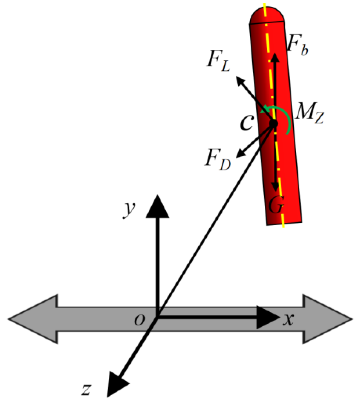
To study the effects of transverse drag velocity on the vehicle, a three-degree-of-freedom model is established, as shown in Figure 2. The uncontrolled underwater phase of the vehicle is primarily affected by buoyancy force Fb, gravitational force G, lift force FL, drag force FD, and the pitching moment Mz about the center of mass c. With the vehicle exiting the launch tube, AMNT undergoes asymmetric evolution under the influence of transverse drag velocity. After exiting the tube, the vehicle gradually deflects, causing changes in the forces acting upon it. The pitch moment Mz induces a certain pitch motion in the vehicle and obtains a certain magnitude of positive and negative pitch angular velocity. Under certain force conditions, it alters the vehicle’s attitude as well as FL and FD.
Figure 3 shows the dimensions of the ventilated shoulder cavity in the vehicle. To facilitate the study, the physical quantities involved in this paper are dimensionless. The physical quantities and dimensionless parameters are shown in Table 2. During the three-degree-of-freedom motion of the vehicle, the closure angle θ evolves in real time with the ventilated cavity, significantly influencing the cavity’s stability.
The calculation method for the dimensionless parameter is as follows.
The dimensionless water depth at which the vehicle is located:
H ¯ = h / L
The vertical dimensionless displacement of the vehicle:
Y ¯ = y / L
The transverse dimensionless displacement of the vehicle:
X ¯ = x / L
The dimensionless difference between the cavity length of the OSS and the CSS:
Δ L ¯ = Δ L / D
The Froude number during the motion of the vehicle:
F r = V / g D
This experiment investigated the effects of transverse velocity and vehicle head shape on the evolution of ventilated cavities in a three-degree-of-freedom vehicle. The experimental parameters are listed in Table 3. E1-PE20-Frl9.3-vt0.2 denotes the first set of experimental conditions for the hemispherical-headed vehicle. Environmental pressure is 20 kPa. The Froude number when the vehicle’s bottom exits the launch tube is 9.3. The transverse velocity of the launch tube is 0.2 m/s.

2.3. Experimental Reliability Verification

2.3.1. Repeatability Test

To demonstrate the feasibility and reliability of the experiment, three replicate experiments are conducted: test1, test2, and test3. Figure 4a compares the evolutionary morphology of the attached cavity with partial velocity curves of the vehicle. The morphology of the attached cavity indicates that the results from the three test sets exhibit high reproducibility. Figure 4b further presents the relative error analysis diagram for the vehicle’s velocity. As shown in the figure, the maximum relative error across the three operating conditions does not exceed 2.1%, indicating that experimental errors are limited and controllable.

2.3.2. Measurement Uncertainty Analysis

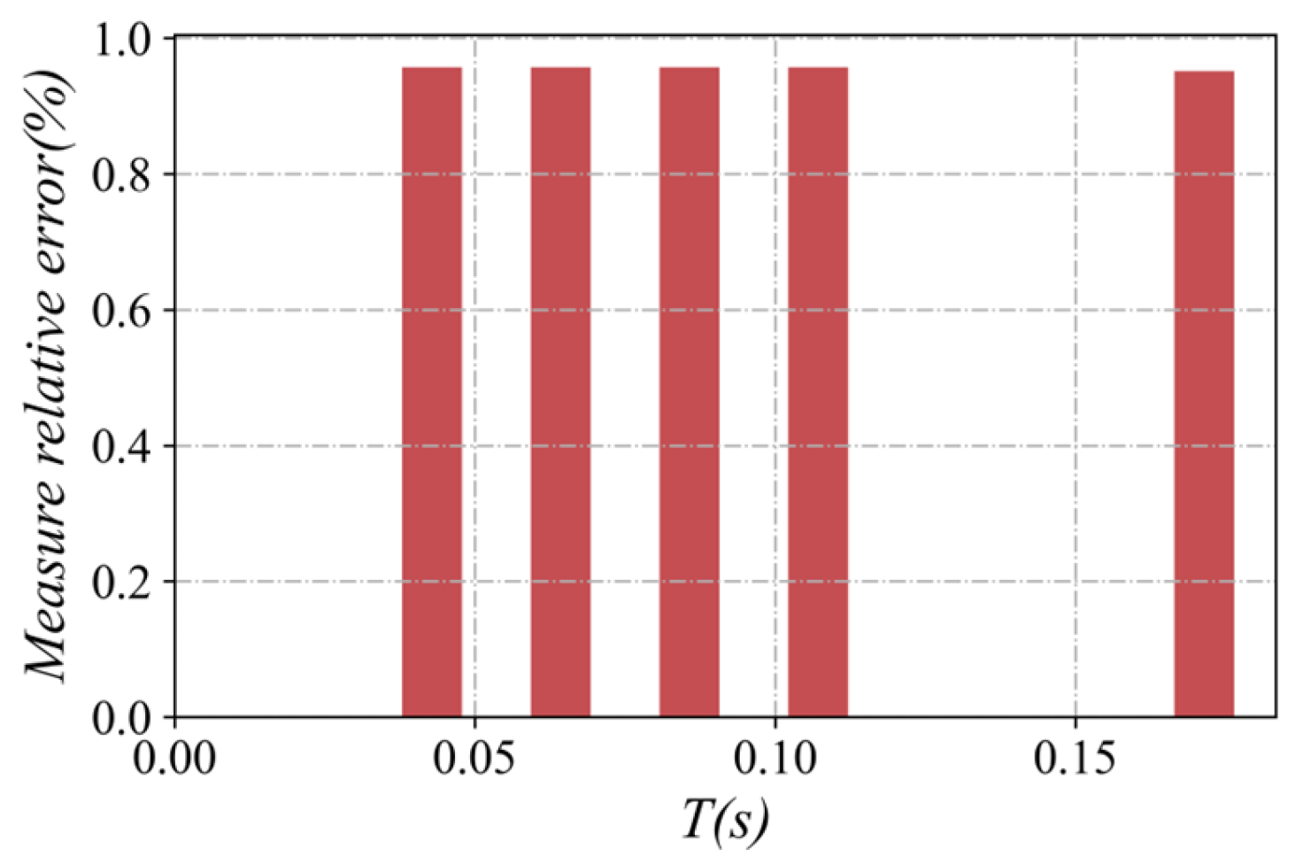
This section discusses measurement errors that occur at various positions of the vehicle during flight. Measurement errors are primarily caused by variations in the camera lens’s shooting angle during vehicle movement. Taking vehicle diameter as an example, Figure 5 shows the relative measurement error of the diameter of vehicles exiting the launch tube section. As shown in the figure, the maximum relative error in vehicle diameter at different positions is 0.96%, meeting the experimental requirements.

3. Results

3.1. Effect of Transverse Velocity on the Ventilated Cavity of a Hemispherical-Headed Vehicle

This section first analyzes the E1 condition with a transverse velocity of 0.2 m/s, an environmental pressure of 20 kPa, and a hemispherical vehicle head. Figure 6 shows the underwater motion attitude of the vehicle under the E1 condition, and the underwater evolution of the vehicle’s ventilated shoulder cavity. During the initial stage of the vehicle’s motion, influenced by the transverse movement, AMNT flows asymmetrically out of the tube, H ¯ = 1.39. The transverse inflow suppresses the development of AMNT, while the transverse flow pushes the gas toward the vehicle’s OSS. A large air mass forms on the OSS of the vehicle. As the vehicle exits the launch tube, the volume of gas on OSS increases continuously, intensifying the asymmetry of AMNT, at H ¯ = 1.14. The shoulder of the vehicle forms a ventilated cavity that wraps around part of the vehicle’s surface. Due to changes in the flow field, a cavity pre-positioning point appears above the venting seam. The cavity’s pre-positioning point creates a low-pressure zone for gas flowing out through the venting seam, inducing adjacent gas to form a raised striped surface. The surface waves on OSS of the cavity intensify due to the attraction of the raised striped cavity and the disturbance of the transverse velocity, at H ¯ = 1.00. The raised striped surface near the CSS rapidly increases in size, delaying the thinning rate of the CSS cavity, at H ¯ = 0.85. It is noteworthy that the presence of the raised striped cavity also causes the location where the ventilated shoulder cavity separates from AMNT to shift from the thin air layer region on the CSS to the OSS, at H ¯ = 0.70. Until the vehicle exits the tube, the residual air mass near the tube is completely disconnected from the ventilated cavity. The residual air mass near the tube shed from the OSS at H ¯ = 0.56 and contacted the tail cavity at H ¯ = 0.41. As the attitude angle increases, the shoulder cavities on both sides of the vehicle exhibit significant asymmetry, with the cavity ends gradually deflecting toward the OSS. The mixing zone at the end of the CSS cavity caused by the raised striped cavity also shed during the attitude deflection of the vehicle, at H ¯ = 0.27–0.14.
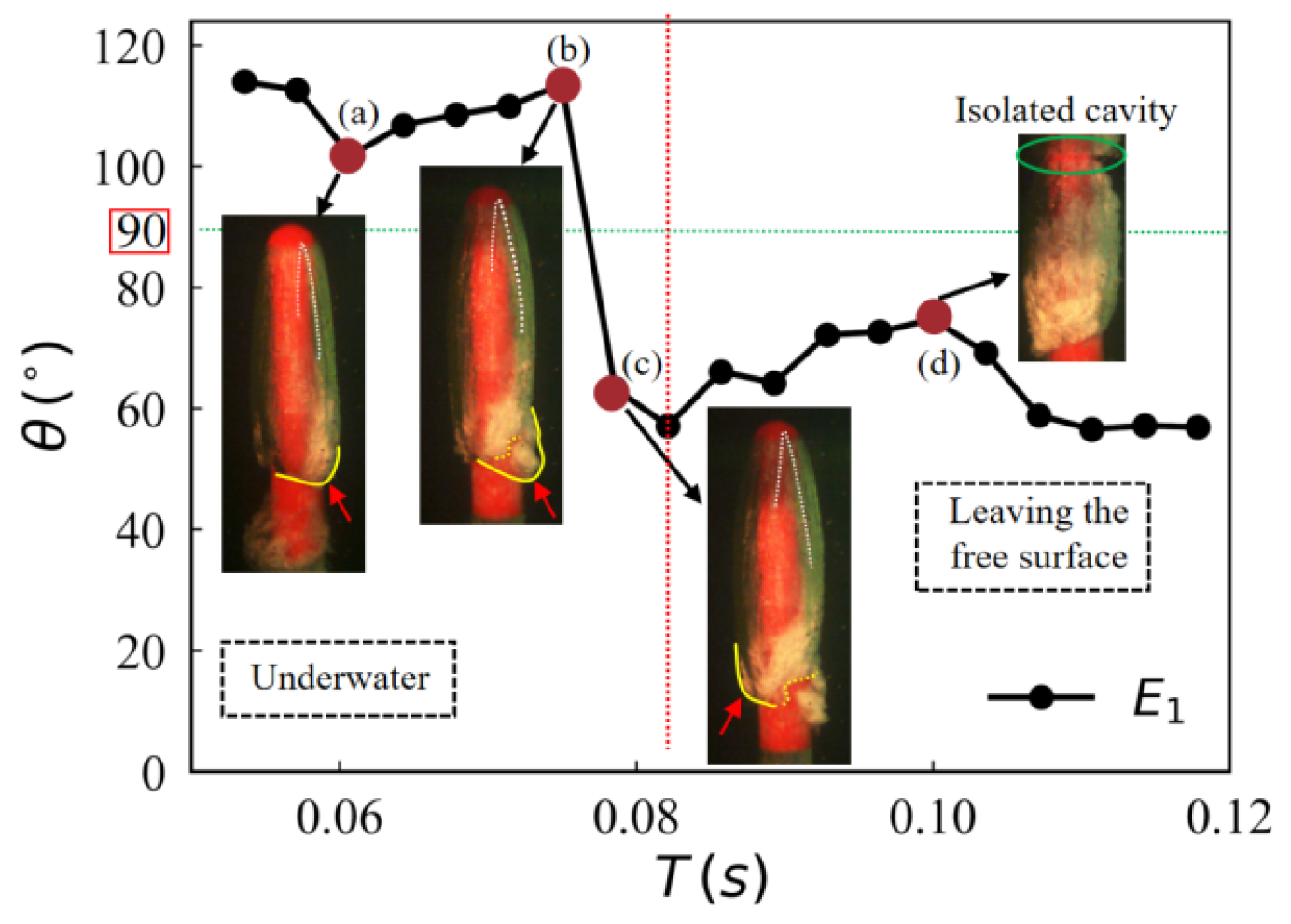
After exiting the tube, the angle between the CSS generatrix of the vehicle and the closure line at the end of the ventilated cavity also undergoes significant changes due to transverse drag motion, Figure 7. When the vehicle exits the tube, influenced by the raised striped cavity, the cavity on the CSS becomes relatively large after separation from AMNT. This results in the angle θ between the CSS generatrix and the closure line at the end of the ventilated cavity exceeding 90°, as seen in Figure 7(a). Due to the influence of the cavity end shedding on the CSS, θ continuously increases, as seen in Figure 7(b). After the air mass at the cavity end is shed, the closure angle θ rapidly decreases below 90° under the influence of the transverse velocity, as seen in Figure 7(c). At this time, the length of the CSS is shorter than that of the OSS. With the vehicle out of the water, the cavity is compressed under the effect of free surface blockage, and the closure angle θ gradually increases again. When T = 0.1 s, the ventilated cavity traverses the free surface and fractures, forming an isolated cavity collapse. This cavity exhibits a tendency to slide down the vehicle surface, Figure 7(d). The closure angle θ gradually decreases during the relative motion between the cavity and the vehicle. As θ approaches 90°, the symmetry of the airflow on both sides of the cavity increases. The variation in the closure angle θ shows that the emergence of a pre-positioning point of the cavity and the shedding of the cavity end significantly affect the symmetry of the cavity in the three-degree-of-freedom motion.
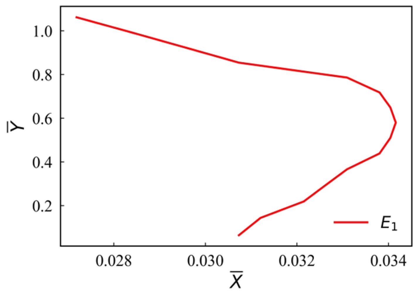
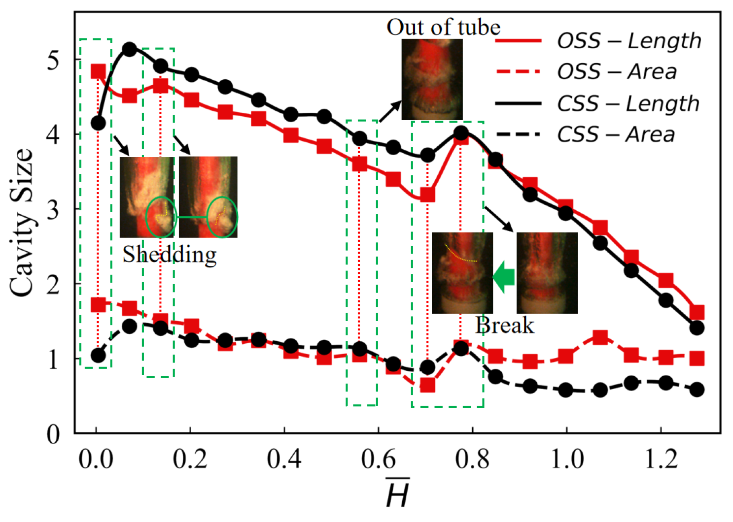
As the vehicle exits the launch tube, the tube’s constraints on the vehicle diminish, causing the vehicle to possess a certain attack angle and pitch angular velocity at the moment of exiting the tube. To quantitatively evaluate the attitude and trajectory changes in an underwater vehicle’s motion, its underwater movement trajectory is shown in Figure 8. Under the effects of transverse flow and lift resistance, the vehicle undergoes transverse deceleration motion and movement opposite the launch tube. As the attitude angle increases, the cavity on the CSS and the OSS(OSS) exhibits asymmetry, as seen in Figure 9. The shoulder cavity of the vehicle continuously expelled gas, gradually increasing in size. The transverse motion of the launch tube gives the vehicle a transverse drag velocity out of the tube, while also causing asymmetry in the exit of AMNT. The OSS cavity develops rapidly, with both its length and projected area exceeding those of the CSS cavity before separating from AMNT. When H ¯ = 0.7, the ventilated cavity and AMNT are fractured. Due to the influence of the raised striped surface, the length of the CSS cavity gradually exceeds that of the OSS cavity. However, it is noteworthy that under the combined effects of the transverse flow’s suppression on the CSS and the low-pressure zone on the OSS, even when the CSS striped cavity induces the OSS cavity, the projected area of the confronted opposing cavity does not exhibit significant changes as the cavity length. When H ¯ = 0.005, the end of the cavity’s CSS is shed, and its cavity length rapidly decreases.

3.2. Effects of Different Transverse Velocities on the Evolution of Ventilated Cavities

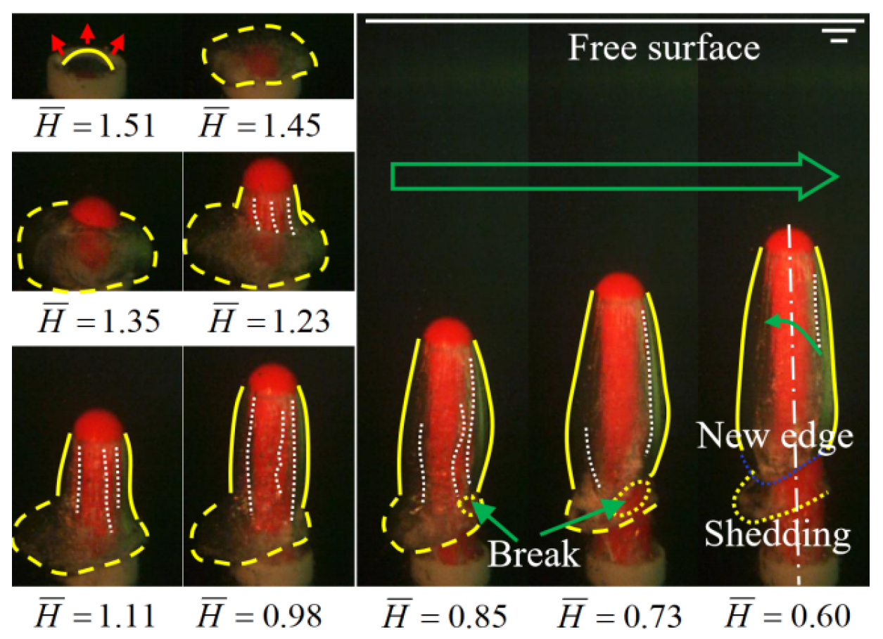
At a transverse velocity of 0.2 m/s, the pre-positioning point of the cavity flow influences the gas flow pattern on the CSS and OSS. Asymmetry in the cavity is also observed. This section further analyzes the evolution patterns of the cavity at transverse velocities of 0.4 m/s and 0.6 m/s, building upon the baseline case of 0.2 m/s. Figure 10 illustrates the evolution process of AMNT and shoulder cavity during the vehicle’s exit from the tube at a transverse velocity of 0.6 m/s. At high transverse velocities, the transverse motion of the launch tube and the exit of the vehicle are accompanied by an intensified asymmetry in AMNT, at H ¯ = 1.35. At this time, the projected area of the cavity on the OSS is 1.9 times that on the CSS. In the experiment with vt = 0.6 m/s, initial disturbances in the ventilated cavity are more significant, but no distinct cavity pre-positioning points are observed, at H ¯ = 1.23–1.11. AMNT on the CSS rapidly flows toward the OSS under the high relative velocity between the launch tube and the incoming flow. The cavity at the junction between AMNT and the CSS shoulder cavity is thinned. When H ¯ = 0.98–0.85, drawn by the vehicle exiting the tube, the cavity at the connection point ripped open, forming a breach. As the vehicle continued moving, the breach gradually expanded, at H ¯ = 0.73. AMNT and the shoulder cavity ruptured and separated due to the breach. The residual air mass near the tube sheds on the OSS, at H ¯ = 0.60. As the speed of out the tube increases, the strength of the cavity gradually increases, and the surface disturbance of the cavity weakens.
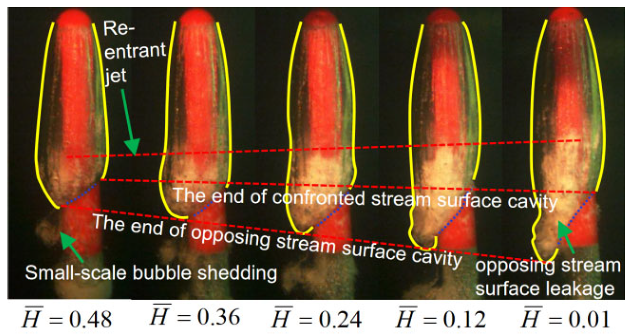
Compared to the low transverse velocity in Section 3.1, the vehicle exhibits more significant attitude changes after exiting the tube during high transverse velocity motion, at H ¯ = 0.48, Figure 11. After AMNT is shed, a re-entrant jet first develops on the OSS of the cavity, at H ¯ = 0.36. From the end boundary of the cavity, it can be seen that the dimensions of the OSS cavity develop rapidly. Under the influence of the vehicle’s attitude angle, the growth rate of the OSS cavity is significantly greater than that of the CSS cavity. As the vehicle moves toward the free surface, the surrounding pressure rapidly decreases, causing the re-entrant jet directed toward the cavity’s leading edge to develop rapidly and fill the cavity’s end, at H ¯ = 0.24. Under the effect of the re-entrant jet, the cavity morphology undergoes further changes. Significant vortex shedding occurs at the OSS of the cavity, at H ¯ = 0.12–0.01.
When vt = 0.4 m/s, the pre-positioning point of the cavity is located on the OSS, and the process of vortex shedding at the cavity end on the OSS can be observed, as shown in Figure 12 (E2). After the shoulder cavity and AMNT separate, a re-entrant jet rapidly forms at the OSS, causing the cavity end to shed, at H ¯ = 0.46. The cavity exhibits a significant hairpin vortex structure, at H ¯ = 0.34. As the vehicle moves, the loops of interlocking hairpin vortices gradually shed, at H ¯ = 0.22–0.00. At vt = 0.6 m/s (E3), the transverse velocity increases significantly, causing the vortex shedding at the OSS cavity to pile up, at H ¯ = 0.12. At this time, the shedding hairpin vortex structure transforms into a piled vortex bag, at H ¯ = 0.01. It is noteworthy that as the transverse speed increases, the flushing intensity of the incoming flow on the cavity’s CSS gradually increases. The vortex structure on the CSS has nearly disappeared, and the flow field is relatively stable. The pre-positioning point of the cavity on the vehicle’s head gradually moves toward the OSS. When the transverse velocity reaches 0.6 m/s, the cavity pre-positioning point nearly disappears. The vortex region on the OSS expands with increasing transverse velocity, while the mixed phase gradually focuses on the OSS, exhibiting distinct differences from the flow structure on the CSS.
To further investigate the effect of transverse velocity on the motion of underwater vehicles, Figure 13 shows the motion attitude of the vehicle after exiting the tube at vt = 0.2 m/s, 0.4 m/s, and 0.6 m/s. As shown in the figure, under the influence of the transverse drag velocity provided by the launch tube, the three-degree-of-freedom vehicle undergoes deceleration along the transverse velocity direction followed by a subsequent reverse motion. In fixed-point launch experiments, the transverse displacement of the vehicle at the moment of exit from the launch tube increases with the increase in the transverse velocity of the launch tube. At the same time, the higher the transverse velocity of the launch tube, the greater the initial horizontal velocity of the vehicle that is exiting the tube, and the longer the deceleration distance along the direction of the transverse velocity. It is noteworthy that during the process of the vehicle exiting the water, the attitude of the vehicle is deflected, and the degree of trajectory deflection in the horizontal reverse displacement increases with the increase in transverse drag velocity. The maximum trajectory deflection at vt = 0.6 m/s is 2.83 times that at vt = 0.4 m/s and 3.47 times that at vt = 0.2 m/s.
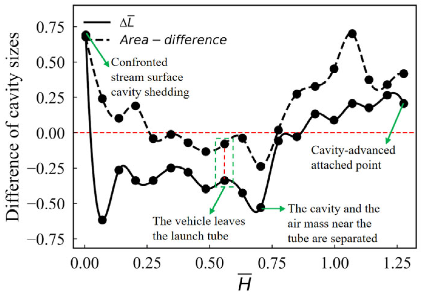
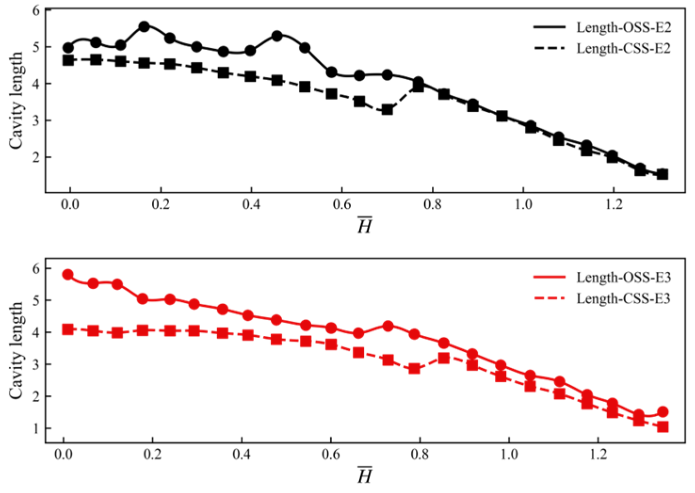
To further investigate the effect of the vehicle’s attitude out of the free surface on the ventilated shoulder cavity, Figure 14, Figure 15 and Figure 16 present the curves showing the dimensions of the cavity’s OSS and CSS, along with their differences Δ L ¯ , for operating conditions E1, E2, and E3, respectively. As shown in Figure 14, when vt = 0.2 m/s, the ventilated shoulder cavity is influenced by the CSS cavity’s pre-positioning point, causing Δ L ¯ to gradually decrease. At H ¯ = 0.78, the cavity length difference is less than zero. The transverse drag velocity significantly neutralizes the effect of the CSS cavity pre-positioning point on the size of the cavity. The trend in the area difference is largely consistent with that of the length difference Δ L ¯ , but the magnitude of the amplitude differs. After the separation of the shoulder cavity and AMNT, although the area difference between the OSS and CSS is negative, it remains close to zero. Until the gas at the cavity end is shed due to the CSS cavity’s pre-positioning point, the dimensional difference between the OSS and CSS cavities rapidly returns to a positive value.
As the transverse velocity increases, the cavity pre-positioning point moves toward the OSS until it disappears, and the cavity size difference between the OSS and CSS is no longer negative. The greater the transverse velocity, the more significantly the difference increases. During three-degree-of-freedom motion, the asymmetric development trend of the cavity attached to the vehicle also increases accordingly. As shown in Figure 15, the Δ L ¯ remains relatively stable before the vehicle exits the tube. As the cavity is about to separate from AMNT, the size of the OSS cavity rapidly increases. After the cavity and AMNT are split, at H ¯ = 0.64, the difference in cavity length decreases. After the vehicle exits the tube, the ventilated cavity forms a new end. The dimensions of the CSS and OSS cavities continuously increase during the environmental pressure decrease. When vt = 0.4 m/s, during the underwater motion of the vehicle, the OSS cavity experiences the shedding of tail vortices thrice. The tail vortex’s shedding induces cavity pulsations while simultaneously initiating a new amplification–attenuation cycle for Δ L ¯ . At H ¯ = 0.40, the vehicle experiences the first vortex shedding (E2) from the OSS cavity. At this time, the length of the cavity on the OSS decreases. After the OSS cavity is shed, the length continues to increase. When the cavity’s bubble-carrying capacity is exceeded, secondary shedding occurs on the OSS cavity at H ¯ = 0.11. At H ¯ = 0.00, the cavity on the OSS shed again. The OSS cavity shedding three times indicates that the unstable shedding of the OSS cavity causes the pulsation peak of Δ L ¯ to gradually decrease. When the transverse velocity increases to 0.6 m/s, the asymmetry of the cavity becomes most significant. The vortex region at the end of the OSS cavity exhibits the most intense turbulent pulsations. Before the vehicle exits the tube, the variation pattern of Δ L ¯ is similar to that of E2. After the vehicle exits the tube, the cavity difference increases steadily. After the trend of shedding appeared at the OSS cavity end, at H ¯ = 0.16, the frequency of cavity difference increase rapidly accelerated. After the vortex group at the end of the OSS cavity is shed, the difference drops back. The Δ L ¯ is most significant in the ventilated cavity under E3 condition. When H ¯ = 0.00, the length of the cavity’s OSS is 1.42 times that of the CSS, and Δ L ¯ is 7.8 times that of condition E2.
It is noteworthy that the shedding of the cavity on the OSS does not affect the development of the cavity size on the CSS, as seen in Figure 16. In conditions E2 and E3, the cavity end on the OSS undergoes pulsation–shedding under the influence of turbulent kinetic energy. The cavity on the CSS rapidly expands in the exiting tube section of the vehicle. When the residual air mass near the tube is shed, the size of the CSS cavity decreases, entering a stable phase of slow growth. When the end of the ventilated cavity is shed, the drag effect of the shed air mass causes a change in the cavity’s closure angle. Figure 17 shows the variation in the closure angle at the cavity end for transverse velocities of 0.2 m/s, 0.4 m/s, and 0.6 m/s. As shown in the figure, the variation patterns of conditions E2 and E3 differ from those of E1. The shedding of the cavity causes a decrease in the cavity end closure angle θ, and after shedding, θ rapidly increases. During the process of the vehicle exiting the water, the ventilated cavity is compressed by the free surface, causing it to expand radially, with θ continuously increasing. As the transverse velocity increases, the cavity end average closure angle gradually decreases, where θ0.6 = 49.18° < θ0.4 = 57.90° < θ0.2 = 80.83°.

3.3. Effect of Vehicle Head Shape on the Evolution of Ventilated Cavities

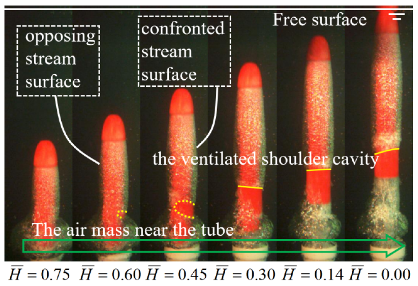
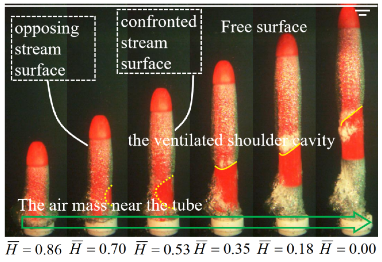
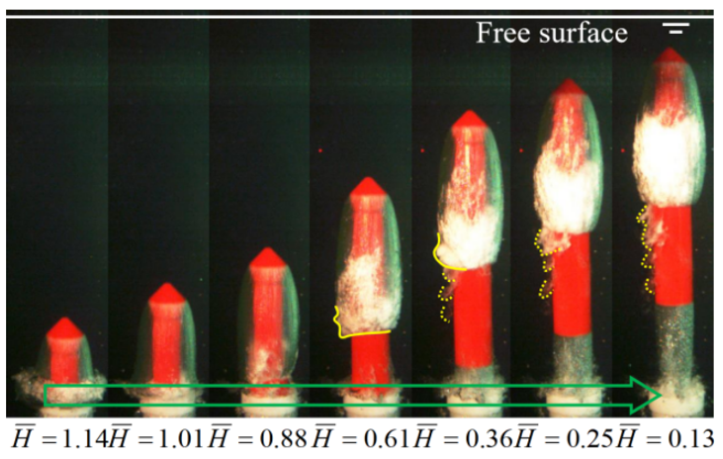
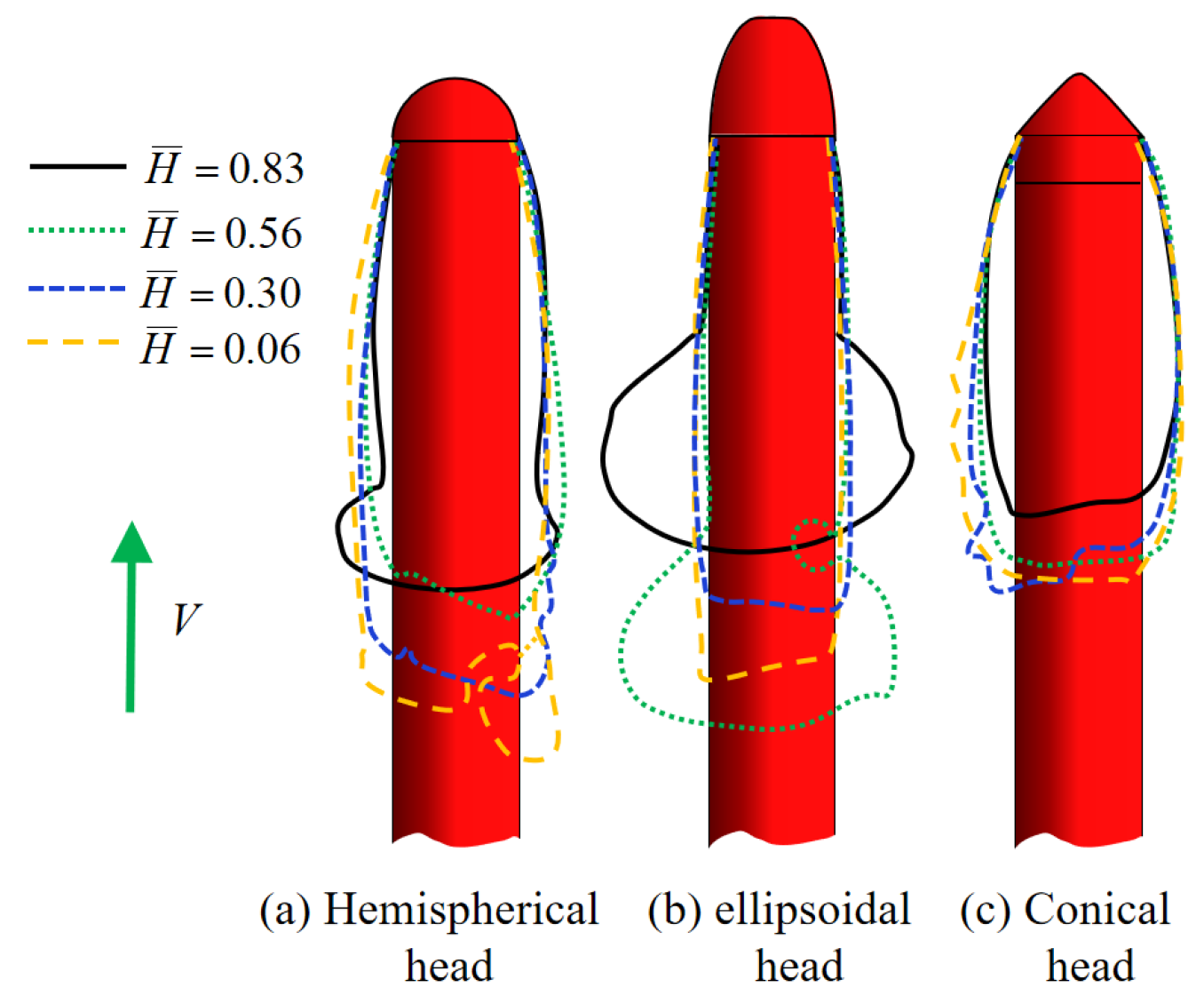
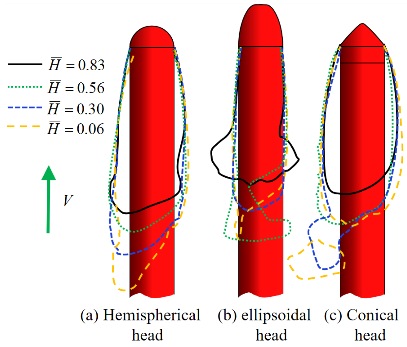
The increase in transverse velocity accelerates the asymmetry of the vehicle’s CSS and OSS. The shoulder flow field instability of the hemispherical-headed vehicle caused the cavity to be positioned forward. As the transverse velocity increases, the force of the flow on the CSS of the vehicle intensifies, causing the cavity’s pre-positioning point to shift toward the OSS. In the above study, it is obtained that the curvature of the shoulder has an effect on the initial position of the cavity in the three-degree-of-freedom motion of the vehicle. To further investigate the evolution of cavities during three-degree-of-freedom motion of the vehicle, this section introduces the three-degree-of-freedom motion of ellipsoidal-headed and conical-headed vehicles at large and small transverse velocity for vt = 0.2 m/s and vt = 0.6 m/s, as shown in Figure 18, Figure 19, Figure 20 and Figure 21. The ellipsoidal head shape of the vehicle suppresses flow separation at the shoulders, with no significant cavity pre-positioning point observed above the venting seam (Figure 18 and Figure 19). The low-pressure zone at the shoulder of the conical-headed vehicle induces AMNT to follow the vehicle shoulder out of the tube, providing favorable initial conditions for the ventilated cavity. The leading edge of the cavity in the conical-headed vehicle originates at the point of curvature change above the venting seam, as shown in Figure 20 and Figure 21. The presence of the ventilated shoulder cavity protects the non-wetted surface area of the vehicle from hydrodynamic forces. Therefore, under the same initial conditions, the larger the surface area of the cavity covering the underwater vehicle, the more favorable it is for reducing the vehicle’s underwater resistance. The unsteady evolution of the cavity leads to changes in the area of the non-wetting zone. Moreover, the transverse velocity causes asymmetric development of the cavity on the CSS and OSS of the vehicle. Without a cavity pre-positioning point, the closure position of the OSS cavity is shifted rearward. The closure at the end of the OSS cavity generates a re-entrant jet that causes the cavity to shed. Then, under the influence of the transverse flow, the CSS cavity re-envelopes the OSS cavity.
When vt = 0.2 m/s, the transverse velocity has a low impact on the attitude of the ellipsoidal-headed vehicle and the attached cavity, as shown in Figure 18, where H ¯ = 0.00. At the junction between the CSS cavity and AMNT, a cavity rupture point occurs when H ¯ = 0.60. Moreover, as the transverse velocity increases, the location of the cavity rupture point shifts forward, and the degree of cavity rupture increases as shown in Figure 19, where H ¯ = 0.70–0.53. After the vehicle exits the launch tube, the shoulder cavity is separated from AMNT. The ventilated cavity forms a new closure end, as shown in Figure 18, where H ¯ = 0.30, and Figure 19, where H ¯ = 0.35. The re-entrant jet at the cavity’s end is shed as the vehicle moves out of the water. The attitude angle of the vehicle’s motion also increases with the increase in transverse velocity. When vt = 0.6 m/s, the ellipsoidal-headed vehicle exhibited a significant attitude angle after exiting the launch tube. The dimensions of the OSS cavity are also significantly larger than those of the CSS cavity due to the effect of the attitude angle. The re-entrant jet region at the cavity end gradually shifts toward the OSS, where H ¯ = 0.18. And under the flushing action of the transverse flow, it is shed from the OSS of the cavity, where H ¯ = 0.00.
Compared to the thin-walled cavity formed by an ellipsoidal-headed vehicle, a conical-headed vehicle has a greater capacity to carry AMNT out of the tube. During the vehicle exit from the tube, nearly the entire air mass near the tube is carried out, as shown in Figure 20, where H ¯ = 0.88, and Figure 21, where H ¯ = 0.79. The ventilated cavity of the conical-headed vehicle generates a high-intensity re-entrant jet directed toward the cavity’s leading edge, as shown in Figure 20, where H ¯ = 0.61. Under the effect of the transverse flow, a series of vortex shedding occurs at the OSS, as shown in Figure 20, where H ¯ = 0.36–0.13. When vt = 0.6 m/s, the OSS cavity shedding from the conical-headed vehicle is similar to that of a hemispherical-headed vehicle, H ¯ = 0.40. Under the action of high-speed transverse flow, shed vortices accumulate into vortex bags and shed, where H ¯ = 0.28–0.17. During the three-degree-of-freedom motion, the volume of gas shed from the cavity end of hemispherical and conical-headed vehicles is significantly greater than that of ellipsoidal-headed vehicles.
To further investigate the evolution patterns of cavities during the motion of three-degree-of-freedom vehicles, Figure 22 and Figure 23, respectively, illustrate schematic diagrams of the development process of the ventilated shoulder cavity at typical water depths for three vehicle head types at vt = 0.2 m/s and vt = 0.6 m/s. As shown in Figure 22, when vt = 0.2 m/s, the air cavity rapidly expands radially after AMNT of the hemispherical-headed vehicle is shed. During the shedding process at the cavity’s end, the cavity undergoes axial stretching once more. The shoulder cavity of the ellipsoidal-headed vehicle exhibits a significant pressure gradient at the shoulder region. Most of AMNT is shed as the vehicle moves, finally forming a thin-walled cavity. The conical-headed vehicle exhibits a significantly larger radial dimension than hemispherical-headed and ellipsoidal-headed vehicles due to the effect of the low-pressure zone at the shoulder. When the vehicle’s head touches the free surface, wF1 = 1.24 < wE1 = 1.63 < wG1 = 1.87. When vt = 0.6 m/s, the high transverse velocity causes the cavity to deflect significantly toward the OSS, resulting in a rapid increase in cavity size on the OSS. As the transverse velocity increases, the thickness of the thin-walled cavity on the CSS and OSS of the ellipsoidal-shaped vehicle does not change significantly. The thickness of the cavity on the CSS of the hemispherical and conical heads is significantly smaller than that on the OSS. Moreover, after gas shedding at the end of the shoulder cavity of the conical-headed vehicle, a significant pulsation phenomenon appeared in the cavity, with the thickness of the CSS cavity increasing instantaneously.
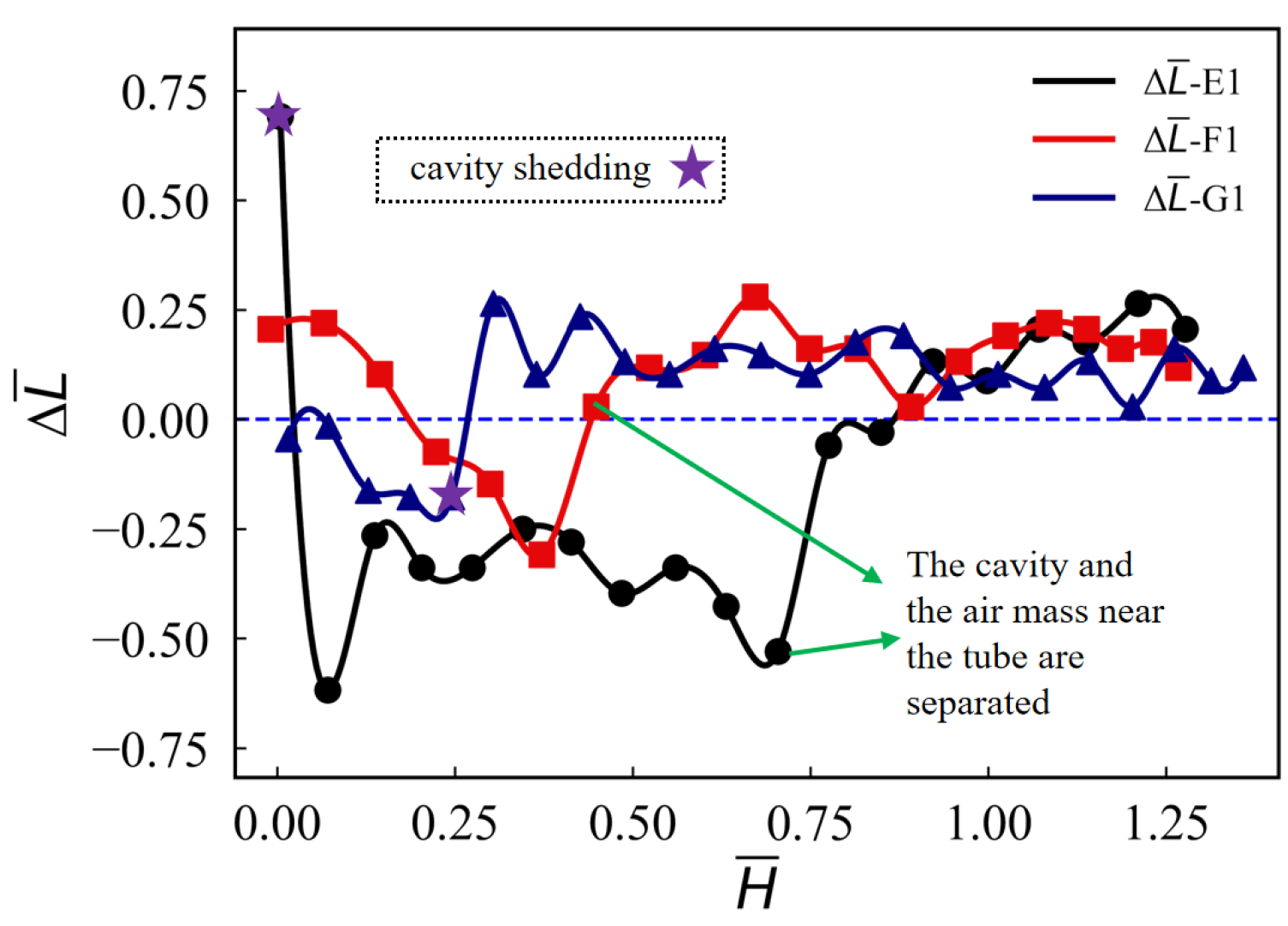
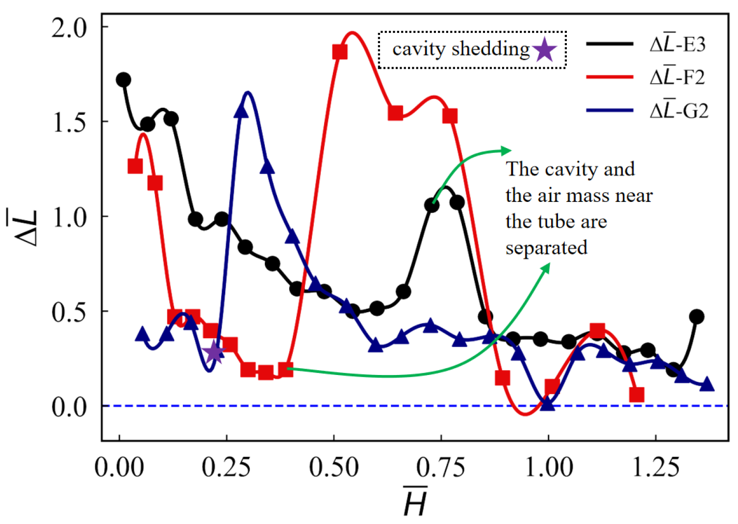
Figure 24 and Figure 25 show the differences between the cavity’s OSS and CSS at both large and small transverse velocities as the shape of the vehicle’s head changes. Cavity shedding is the primary cause of cavity size pulsation. As shown in Figure 24, when there is no cavity pre-positioning point, at vt = 0.2 m/s, Δ L ¯ are all near zero, with small numerical differences. When the shoulder cavity separates from AMNT or the shoulder cavity end sheds, causing the closure line at the shoulder cavity end to re-establish, Δ L ¯ oscillates, and the cavity length of the CSS becomes greater than that of the OSS. As the transverse velocity increases, the pulsation amplitude increases, as seen in Figure 25. Before the cavity is shed, Δ L ¯ rapidly increases in size. Once it exceeds the vehicle’s bubble-carrying capacity, the cavity is shed. The cavity (F2) of the ellipsoidal-headed vehicle exhibited values of 1.68 and 1.07 during the separation from AMNT and cavity shedding, respectively, which are significantly higher than the other two head types. This is due to the unique thin-walled structure of the ellipsoidal-headed vehicle, causing the cavity to undergo primarily axial dimensional changes during pulsation and shedding. Since the conical-headed vehicle almost completely entrained the entire air mass near the tube, its Δ L ¯ changes primarily occurred during the cavity shedding process. After cavity shedding, Δ L ¯ rapidly decreased.
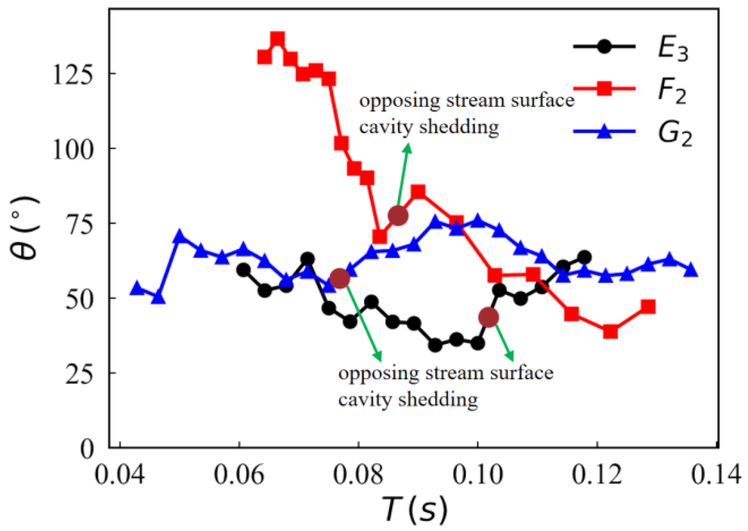
As the dimensions of the cavity on the CSS and OSS change, the closure angle at the cavity’s end also exhibits significant changes. As shown in Figure 26 and Figure 27, under the combined effects of strong closure at the cavity end and high closure angle, the closure angle at the end of the ventilated cavity of the conical-headed vehicle exhibits the highest stability (G1, G2). Following the experience of OSS cavity shedding, the closure angle at the cavity end exhibits a slight increase followed by a decrease. After the cavity of the ellipsoidal-headed vehicle (F1) separates from AMNT on the CSS, the closure angle at the cavity’s end rapidly decreases. The OSS cavity fully develops until it sheds. The size of the cavity OSS is reduced, leading to the increase in the closure angle at the cavity end. Under the influence of high transverse velocity, the closure angle at the cavity end of the ellipsoidal-headed vehicle (F2) is significantly changed. After the vehicle exits the tube, the closure angle rapidly decreases. After the cavity is shed, the closure angle undergoes a brief increase, then continues to decrease. The closure angle at the cavity end of the hemispherical-headed vehicle gradually decreases after the vehicle exits the tube, with a reduction rate significantly lower than that of the ellipsoidal-headed vehicle. Following cavity shedding, the closure angle increases slowly. At both large and small transverse velocities, the initial value of the closure angle at the cavity end of the ellipsoidal-headed vehicle is greater than 90°. When vt = 0.6 m/s, the initial value of the closure angle exceeds 120°. However, the initial values of the closure angle at the end of the cavity for the conical-headed vehicle are all less than 90°. This is caused by the interaction between the ventilated shoulder cavity and AMNT. The shoulder cavity of the ellipsoidal-headed vehicle and AMNT are broken off on the CSS. The breakpoint shifted toward the weakened cavity, causing the cavity on the CSS to be larger than that on the OSS at the initial moment. This also resulted in the initial closure angle of the cavity exceeding 90°. The conical-headed vehicle entrains AMNT into the shoulder cavity, making it part of the shoulder cavity. The closure angle at the cavity end is primarily affected by the transverse inflow, with the initial closure angle being less than 90°. As the transverse velocity increases, the closure angle decreases significantly.
Under the effect of transverse velocity, the asymmetric development of the ventilated shoulder cavity and the nonuniform distribution of the re-entrant jet at the cavity’s end significantly influence the interaction patterns between the shoulder and tail cavities. Figure 28 compares the shoulder–tail contact and interaction patterns of three vehicles with different head shapes at transverse velocities of vt = 0.2 m/s and vt = 0.6 m/s. The results are presented in Table 4. As shown in the figure, the ventilated cavity of the ellipsoidal-headed vehicle is a thin-walled air layer. When the ventilated shoulder cavity is pushed toward the tail cavity, it comes into contact with the tail cavity (Figure 28c, F1). When vt = 0.6 m/s (Figure 28d, F2), the closure angle at the cavity end becomes more significant. The OSS of the ventilated cavity first contacts the tail cavity. The ventilated shoulder cavity gradually wraps around the tail cavity, exhibiting a “layered progressive fusion” pattern. The contact point between the shoulder cavity and tail cavity of the hemispherical-headed vehicle is located underwater section (Figure 28a, E1; Figure 28b, E3). After the tail cavity contacts the shoulder cavity’s OSS, the tail cavity concave on the OSS is formed by the re-entrant jet reflected at the end of the shoulder cavity. Until the shoulder–tail cavities complete contact, the two cavities undergo a “wrapping and pinching fusion” mode under the action of the strongly closed mixed jet. The contact point between the shoulder cavity and tail cavity of the conical-headed vehicle is located near the free surface (Figure 28e, G1; Figure 28f, G2). The CSS shoulder cavity is almost entirely out of water, leaving only the partially mixed-phase cavity enclosed by the closure line at the shoulder cavity’s end and the OSS. At this time, the axial advance of the re-entrant jet within the cavity accelerates. The mixed-phase end of the OSS exhibits a “unilateral contact fusion” pattern with the tail cavity. It is noteworthy that the ability of different vehicle head shapes to carry AMNT out of the tube indirectly affects the amount of residual gas shed after the tail cavity exits the tube. During the process of exiting the tube, part of AMNT slips off around the tail cavity, forming a significant residual gas volume. The conical-headed vehicle almost completely entrained the entire air mass near the tube out of the tube, with a relatively small amount of gas shedding below the tail cavity. Moreover, with the transverse velocity increase, the shedding residual gas gradually exhibits a greater tendency to move toward the OSS.

4. Conclusions

A small-scale three-degree-of-freedom decompression model experiment is used. Under the effect of transverse velocity, the evolution mechanism of the ventilated shoulder cavity in three underwater vehicles with typical head shapes (hemispherical, ellipsoidal, and conical) is investigated, along with the interaction between the asymmetric shoulder cavity and the tail cavity. The main findings are as follows:
(1)
The transverse motion of the launch tube induces asymmetry in the flow of AMNT and the ventilated shoulder cavity toward the OSS. The shoulder region of hemispherical-headed vehicle is prone to developing cavity pre-positioning point. The cavity pre-positioning point appearing on the CSS significantly increases the axial dimension of the CSS cavity. However, the flushing effect of the transverse flow on the CSS cavity suppresses the difference in the projected area between the CSS and OSS cavity caused by axial dimensional changes. Under the effect of transverse velocity, the underwater trajectory of the vehicle underwent transverse deceleration and movement in the direction opposite that of the launch tube.
(2)
The transverse velocity’s increase leads to the transverse displacement’s increase in the vehicle out of the tube. The degree of trajectory deflection due to horizontal reverse displacement after the vehicle exits the tube increases with increasing transverse velocity. The cavity pre-positioning point of the hemispherical-headed vehicle’s shoulder cavity moves toward the OSS as the transverse velocity increases, until it disappears. The OSS and CSS cavity difference Δ L ¯ increases with increasing transverse velocity. The flushing action of the transverse flow enhances the stability of the CSS cavity. The shedding phenomenon at the end of the OSS cavity is enhanced with increasing transverse velocity. The shedding pattern of cavities has transformed from a hairpin vortex shedding one by one to a vortex pile-up shedding. The primary reasons for varying the closure angle at the cavity end are separation from AMNT and shedding at the cavity end.
(3)
The starting position of the cavity’s leading edge is directly related to the curvature of the vehicle’s head shape. The shoulder curvature of the conical-headed vehicle undergoes an abrupt change. The starting position of the cavity’s leading edge is located at the point of maximum curvature above the venting seam. The hemispherical-headed vehicle is prone to developing a pre-positioning point. The elliptical-headed vehicle exhibits good shoulder transition with no significant pre-positioning point. The gas shedding volume at the end of the ventilated cavity of an ellipsoidal-headed vehicle is minimal. Under small transverse velocity (vt = 0.2 m/s), if no cavity pre-positioning point exists, the cavity difference Δ L ¯ oscillates around the zero mark. The trajectory deflection is minimal after the vehicle exits the tube. Under large transverse velocity (vt = 0.6 m/s), the cavity difference Δ L ¯ undergoes violent changes when the closing line at the cavity end regenerates. The trajectory deflection is greatest after the vehicle exits the tube. Due to the influence of the vehicle’s ability to carry AMNT out of the tube, the initial closure angle at the end of the cavity of the ellipsoidal-headed vehicle is greater than 90°.
(4)
Under the influence of transverse velocity, the asymmetrical development of the ventilated shoulder cavity occurs. The shoulder–tail cavity of the ellipsoidal-headed vehicle exhibits a “layered progressive fusion” pattern. The two cavities of the hemispherical-headed vehicle exhibit a “wrapping and pinching fusion” pattern. The contact point between the shoulder cavity and tail cavity of the conical-headed vehicle is located near the free surface. The mixed-phase end of the OSS exhibits a “unilateral contact fusion” pattern with the tail cavity. Moreover, as the transverse velocity increases, the shedding residual gas gradually moves toward the OSS.
In the manuscript, the vehicle’s three degrees of freedom motion is achieved by using vertical launch technology combined with the transverse movement of the launch tube. In the next stage of experimental research, the pan-tilt functionality of the launch tube will be added. Multi-degree-of-freedom motion of underwater vehicles will be achieved. Research on vehicle deviation angles and self-rotation will be expanded. During the experiment, it is difficult to obtain the flow field distribution of the vehicle’s transient motion. The next step will involve reconstructing the experimental flow field by integrating Fluent fluid simulation with deep learning methods such as LSTM and U-net.

Author Contributions

J.W.: Writing—original draft, Investigation, Data curation. D.S.: Methodology. G.M.: Methodology, Funding acquisition. J.L.: Methodology. R.W.: Data curation. All authors have read and agreed to the published version of the manuscript.

Funding

This work is supported by the National Natural Science Foundation of China (No. 52431010), the National Natural Science Foundation of China (No. 52271308), the National Natural Science Foundation of China (No. 52371309), the Excellent Youth Foundation of Heilongjiang Province of China (No. YQ2023E036).

Data Availability Statement

The data that support the findings of this study are available within the article.

Conflicts of Interest

The authors declare no conflicts of interest.

References

  1. Zhang, S.; Xu, H.; Sun, T.; Duan, J. Water-exit dynamics of a ventilated underwater vehicle in wave environments with a combination of computational fluid dynamics and machine learning. Phys. Fluids 2024, 36, 023312. [Google Scholar] [CrossRef]
  2. Mirsandi, H.; Smit, W.; Kong, G.; Baltussen, M.; Peters, E.; Kuipers, J. Bubble formation from an orifice in liquid cross-flow. Chem. Eng. J. 2020, 386, 120902. [Google Scholar] [CrossRef]
  3. Zhuang, Q.; Zhang, H.; Zhao, C.; He, X.; Liu, Y.; Liu, Z.; Li, S.; Zhu, R.; Wu, D. Effects of the launch parameters on trans-phase stability performance and mechanism for submarine-launched missiles model. Ocean Eng. 2023, 283, 115083. [Google Scholar] [CrossRef]
  4. Lu, Q.; Ma, X.; Zhao, J.; Shen, L. A Review on Research of Load Reduction and Ballistic Stability During Cross-Media Water Entry Processes. J. Mar. Sci. Eng. 2025, 13, 703. [Google Scholar] [CrossRef]
  5. Wu, Q.; Wang, K.; Kong, D.; Zhang, J.; Liu, T. Numerical simulation of subsonic and transonic water entry with compressibility effect considered. Ocean Eng. 2023, 281, 114984. [Google Scholar] [CrossRef]
  6. Hao, L.; Zhang, H.; Yang, Q.; Liu, T.; Huang, B. Experimental investigation on the ventilated cavitating flow characteristics around an axisymmetric body with an unsteady ventilation. Ocean Eng. 2024, 313, 119307. [Google Scholar] [CrossRef]
  7. Zhang, D.; Zhang, J.; Sun, T.; Jiang, Y. Ventilated cavity dynamics of an axisymmetric body under the influence of a structure. Phys. Fluids 2023, 35, 055112. [Google Scholar] [CrossRef]
  8. Yu, A.; Li, L.; Zhou, D. Large eddy simulation of the cavity shedding characteristics of ventilated cavitation around the underwater vehicle. Ocean Eng. 2024, 301, 117546. [Google Scholar] [CrossRef]
  9. Qu, Z.; Cui, J.; Chen, X.; Huang, X.; Ma, G.; Qiu, G. Study on vortex structure and hydrodynamic characteristics of water-exit projectile with shoulder ventilation. Ocean Eng. 2024, 313, 119622. [Google Scholar] [CrossRef]
  10. Ceccio, S.L. Friction drag reduction of external flows with bubble and gas injection. Annu. Rev. Fluid Mech. 2010, 42, 183–203. [Google Scholar] [CrossRef]
  11. Skrucany, T.; Semanova, S.; Milojević, S.; Ašonja, A. New technologies improving aerodynamic properties of freight vehicles. Appl. Eng. Lett. 2019, 4, 48–54. [Google Scholar] [CrossRef]
  12. Shereena, S.G.; Vengadesan, S.; Idichandy, V.G.; Bhattacharyya, S.K. CFD study of drag reduction in axisymmetric underwater vehicles using air jets. Eng. Appl. Comput. Fluid Mech. 2013, 7, 193–209. [Google Scholar] [CrossRef]
  13. Gan, N.; Yao, X.; Su, B.; Cui, X. Study on the dynamic behaviors of a near wall ventilated bubble using OpenFOAM. Ocean Eng. 2022, 257, 111650. [Google Scholar] [CrossRef]
  14. Gao, S.; Shi, Y.; Pan, G.; Quan, X. A study on the performance of the cavitating flow structure and load characteristics of the vehicle launched underwater. Phys. Fluids 2023, 34, 125108. [Google Scholar] [CrossRef]
  15. Gao, S.; Shi, Y.; Pan, G.; Quan, X. A study on the cavitation vortex dynamics and loads of water-exiting axisymmetric projectile. Phys. Fluids 2023, 35, 085112. [Google Scholar] [CrossRef]
  16. Gao, S.; Shi, Y.; Pan, G.; Quan, X. Simulation of the wake vortex and trajectory characteristics of successively launched multiple projectiles. Ocean Eng. 2022, 249, 110962. [Google Scholar] [CrossRef]
  17. Guo, Z.; Zhao, Y.; Zhang, X.; Lyu, X. On the cavity flow of a cylinder exiting water obliquely. Ocean Eng. 2023, 281, 114683. [Google Scholar] [CrossRef]
  18. Chen, Y.; Li, J.; Gong, Z.; Chen, X.; Lu, C. LES investigation on cavitating flow structures and loads of water-exiting submerged vehicles using a uniform filter of octree-based grids. Ocean Eng. 2021, 225, 108811. [Google Scholar] [CrossRef]
  19. Manshadi, M.; Hejranfar, K.; Farajollahi, A. Effect of vortex generators on hydrodynamic behavior of an underwater axisymmetric hull at high angles of attack. J. Vis. 2017, 20, 559–579. [Google Scholar] [CrossRef]
  20. Zhang, L.; Gu, L.; Jiao, J.; Pei, Z.; Wang, R. Effects of cross flow on the launching process of submarine-launched vehicle considering the 6-DOF motion at barrel-exit stage. Ocean Eng. 2024, 309, 118418. [Google Scholar] [CrossRef]
  21. Liu, T.; Huang, B.; Wang, G.; Zhang, M. Experimental investigation of ventilated partial cavitating flows with special emphasis on flow pattern regime and unsteady shedding behavior around an axisymmetric body at different angles of attack. Ocean Eng. 2018, 147, 289–303. [Google Scholar] [CrossRef]
  22. Wang, G.; Kong, D.; Wu, Q.; Liu, T.; Zheng, Y.; Huang, B. Physical and numerical study on unsteady shedding behaviors of ventilated partial cavitating flow around an axisymmetric body. Ocean Eng. 2020, 197, 106884. [Google Scholar] [CrossRef]
  23. Cheng, S.; Quan, X.; Sha, Y.; Yang, Q.; Wang, C.; Xu, Y. Experimental investigation of the underwater ventilated tail cavity at different angles of attack. Ocean Eng. 2022, 261, 111916. [Google Scholar] [CrossRef]
  24. Hao, L.; Liu, T.; Kong, D.; Huang, B.; Wang, G.; Wu, Y. Flow pattern regime and unsteady characteristics of ventilated cavitating flow around the axisymmetric bodies with different headforms. Phys. Fluids 2024, 35, 124103. [Google Scholar] [CrossRef]
  25. Zhao, Q.; Chen, T.; Xiao, W.; Chen, X.; Yao, X.; Wang, W. Research on the characteristics of cavitation flow and pressure load during vertical water exit of different head-shaped vehicles. Ocean Eng. 2022, 265, 112663. [Google Scholar] [CrossRef]
  26. Zhang, X.; Yu, Y.; Zhang, X. Research on multiphase flow field characteristics of underwater gun double-tube parallel firing. Propellants Explos. Pyrotech. 2022, 48, e202300068. [Google Scholar] [CrossRef]
  27. Hu, C.; Wang, G.; Wang, X.; Huang, B. Experimental investigation of inception cavitating flows around axisymmetric bodies with different headforms. J. Mech. Sci. Technol. 2016, 30, 3193–3201. [Google Scholar] [CrossRef]
  28. Lu, J.; Wang, C.; Song, W.; Wei, Y.; Yu, D.; Li, Y. Experimental investigation on interference characteristics of projectiles launched successively underwater. Ocean Eng. 2022, 250, 110824. [Google Scholar] [CrossRef]
  29. Moghimi, M.; Nouri, N.; Molavi, E. Experimental investigation on supercavitating flow over parabolic cavitators. J. Appl. Fluid Mech. 2017, 10, 95. [Google Scholar] [CrossRef]
Figure 1. Schematic diagram of the experimental devices.
Jmse 13 02111 g001
Figure 2. Schematic diagram of forces acting on a vehicle.
Jmse 13 02111 g002
Figure 3. Dimensions of ventilated cavity.
Jmse 13 02111 g003
Figure 4. Repeatability experiments.
Jmse 13 02111 g004
Figure 5. Measure relative error.
Jmse 13 02111 g005
Figure 6. Underwater evolution of the cavity attached to a hemispherical vehicle.
Jmse 13 02111 g006
Figure 7. Relationship between the angle at the end of the ventilation cavity and time.
Jmse 13 02111 g007
Figure 8. Underwater vehicle trajectory of E1.
Jmse 13 02111 g008
Figure 9. The cavity size of E1.
Jmse 13 02111 g009
Figure 10. Evolution of the cavity in the exiting tube section of E3.
Jmse 13 02111 g010
Figure 11. Evolution of underwater cavity of E3.
Jmse 13 02111 g011
Figure 12. Comparison of vortex groups at the end of ventilated cavities.
Jmse 13 02111 g012
Figure 13. Comparison of underwater vehicle motion attitudes.
Jmse 13 02111 g013
Figure 14. Difference in cavity sizes of E1.
Jmse 13 02111 g014
Figure 15. Difference in cavity length of E2 and E3.
Jmse 13 02111 g015
Figure 16. The cavity length of E2 and E3.
Jmse 13 02111 g016
Figure 17. The curve of θ varying with the transverse velocity.
Jmse 13 02111 g017
Figure 18. Evolution of underwater cavity of F1.
Jmse 13 02111 g018
Figure 19. Evolution of underwater cavity of F2.
Jmse 13 02111 g019
Figure 20. Evolution of underwater cavity of G1.
Jmse 13 02111 g020
Figure 21. Evolution of underwater cavity of G2.
Jmse 13 02111 g021
Figure 22. Comparison of ventilated cavities with different head shapes of vt = 0.2 m/s.
Jmse 13 02111 g022
Figure 23. Comparison of ventilated cavities with different head shapes of vt = 0.6 m/s.
Jmse 13 02111 g023
Figure 24. Difference in cavity length with different head shapes of vt = 0.2 m/s.
Jmse 13 02111 g024
Figure 25. Difference in cavity length with different head shapes of vt = 0.6 m/s.
Jmse 13 02111 g025
Figure 26. The curve of θ varying of vt = 0.2 m/s.
Jmse 13 02111 g026
Figure 27. The curve of θ varying of vt = 0.6 m/s.
Jmse 13 02111 g027
Figure 28. Interaction between shoulder and tail cavities of vehicles with different head shapes.
Jmse 13 02111 g028
Table 1. Experimental equipment.
NameInformationOrigin or Manufacturer
Decompression tankDimensions: 2 m × 1.2 m × 2.4 mHarbin Engineering University, Harbin, China
SlideEffective stroke greater than 1.5 m, enabling fully automatic vertical lifting and transverse movement.Harbin Engineering University, Harbin, China
Launch tubeHeight: 0.5 m, with an initial volume chamber and a three-ring seal inside.Harbin Engineering University, Harbin, China
VehicleL/D is approximately 6.5, and the head taper angle is 90°.Harbin Engineering University, Harbin, China
VacuumBipolar rotary vane vacuum pump, pumping speed 70 L/sNanguang Pump Industry Co., Ltd., Wenzhou, China
Air compressorOil-free air compressor, rated discharge pressure 0.7 MPaDongcheng Electromechanical Co., Ltd., Qidong, China
Gas tankDiameter: 0.133 m, Length: 0.33 m, Volume: 4 L, Maximum pressure: 1.25 MPaHarbin Engineering University, Harbin, China
Yellow-headed lampPower: 2000 W, Color temperature: 3200 K, Dimensions: 0.21 m × 0.35 m × 0.4 mTianjin Deshun Film & Television Co., Ltd., Tainjin, China
High-speed cameraPhantom Miro C321, At 1920 × 1080 resolution, the capture speed is 1480 fps.AMETEK, Berwyn, PA, USA
Table 2. Physical quantities and dimensionless parameters.
SymbolDetailsSymbolDetails
FbBuoyancy of vehicleFLLift of vehicle
GGravity of vehicleFDResistance of vehicle
cCenter of gravity of the vehicleMzPitch moment of vehicle
DVehicle diameterFrThe Froude number
LVehicle lengthLBOSS
cavity length
LwCSS cavity length H ¯ Vehicle’s dimensionless water depth
X ¯ Transverse dimensionless displacement of the vehicle Y ¯ Vertical dimensionless displacement of the vehicle
θAngle between the CSS and the closure line at the end of the ventilated cavityFrlThe Froude number at which the vehicle leaves the launch tube
ΔLThe difference between the length of the OSS and the CSS Δ L ¯ The dimensionless difference between the length of the OSS and the CSS
vtTransverse velocity of the launch tubeVlThe speed at which the vehicle leaves the launch tube
Table 3. Experimental condition settings.
NumCaseHead ShapeFrlPdifferencevt (m/s) Detailed Name
1E1Hemispherical9.350.2E1-PE20-Frl9.3-vt0.2
2E2Hemispherical8.050.4E2-PE20-Frl8.0-vt0.4
3E3Hemispherical7.850.6E3-PE20-Frl7.8-vt0.6
4F1Ellipsoid8.550.2F1-PE20-Frl8.5-vt0.2
5F2Ellipsoid8.550.6F2-PE20-Frl8.5-vt0.6
6G1Conical8.550.2G1-PE20-Frl8.5-vt0.2
7G2Conical8.350.6G2-PE20-Frl8.3-vt0.6
Table 4. Contact patterns of shoulder–tail cavities for different vehicles with different head shapes.
Head Shapevt (m/s)Contact PointContact Pattern
Hemispherical0.2Underwaterwrapping and pinching fusion
0.6Underwaterwrapping and pinching fusion
Ellipsoidal0.2Underwaterunilateral contact fusion
0.6Underwaterunilateral contact fusion
Conical0.2Near the free surfaceunilateral contact fusion
0.6Near the free surfaceunilateral contact fusion
Disclaimer/Publisher’s Note: The statements, opinions and data contained in all publications are solely those of the individual author(s) and contributor(s) and not of MDPI and/or the editor(s). MDPI and/or the editor(s) disclaim responsibility for any injury to people or property resulting from any ideas, methods, instructions or products referred to in the content.