Review

From Multi-Field Coupling Behaviors to Self-Powered Monitoring: Triboelectric Nanogenerator Arrays for Deep-Sea Large-Scale Cages

1
Ship and Maritime College, Guangdong Ocean University, Zhanjiang 524005, China
2
School of Electronics and Information Engineering, Guangdong Ocean University, Zhanjiang 524088, China
3
Guangdong Provincial Key Laboratory of Intelligent Equipment for South China Sea Marine Ranching, Guangdong Ocean University, Zhanjiang 524088, China
*
Author to whom correspondence should be addressed.
J. Mar. Sci. Eng. 2025, 13(11), 2042; https://doi.org/10.3390/jmse13112042 (registering DOI)
Submission received: 17 September 2025 / Revised: 15 October 2025 / Accepted: 21 October 2025 / Published: 24 October 2025

Abstract

As global Marine resource development continues to expand into deep-sea and ultra-deep-sea domains, the intelligent and green transformation of deep-sea aquaculture equipment has become a key direction for high-quality development of the Marine economy. Large deep-sea cages are considered essential equipment for deep-sea aquaculture. However, there are significant challenges associated with ensuring their structural integrity and long-term monitoring capabilities in the complex Marine environments characteristic of deep-sea aquaculture. The present study focuses on large deep-sea cages, addressing their dynamic response challenges and long-term monitoring power supply needs in complex Marine environments. The present study investigates the nonlinear vibration characteristics of flexible net structures under complex fluid loads. To this end, a multi-field coupled dynamic model is constructed to reveal vibration response patterns and instability mechanisms. A self-powered sensing system based on triboelectric nanogenerator (TENG) technology has been developed, featuring a curved surface adaptive TENG array for the real-time monitoring of net vibration states. This review aims to focus on the research of optimizing the design of curved surface adaptive TENG arrays and deep-sea cage monitoring. The present study will investigate the mechanisms of energy transfer and cooperative capture within multi-body coupled cage systems. In addition, the biomechanics of fish–cage flow field interactions and micro-energy capture technologies will be examined. By integrating different disciplinary perspectives and adopting innovative approaches, this work aims to break through key technical bottlenecks, thereby laying the necessary theoretical and technical foundations for optimizing the design and safe operation of large deep-sea cages.

1. Introduction

With the global demand for protein resources constantly rising and the gradual depletion of near-shore aquatic ecosystems, the exploration and utilization of Marine resources have been expanding into deep-sea areas. As a key infrastructure for offshore Marine aquaculture, large deep-sea cages are an important support for the sustainable development of the “Blue Granary” initiative, which has been explicitly included in China’s 14th Five-Year Plan and has become a core strategy for promoting high-quality development of the Marine economy. However, the operational reliability and long-term service performance of these cages are severely constrained by the complex and harsh deep-sea environment, which features multi-field coupling effects and encompasses aspects such as wave dynamics, ocean current fluid mechanics, biofouling, and sedimentary geomechanics. This complex interaction poses a severe challenge to the structural integrity of the net cages, often leading to problems such as deformation of the net coating, failure of the mooring system, and decline in aquaculture capacity, thereby hindering the large-scale commercialization process of deep-sea aquaculture [1,2,3,4,5]. Therefore, studying the multi-field coupling dynamic mechanism of large deep-sea cages is not only a fundamental scientific task but also a key engineering requirement for optimizing structural design, enhancing disaster resistance capacity, and supporting the construction of the national Marine ranch system.
Precise and continuous environmental monitoring is crucial for ensuring the safe operation of deep-sea cages, as it can assess the structural health status, aquatic ecological conditions, and aquaculture productivity in real time. The traditional power supply solutions for underwater sensor networks, such as wired cables and chemical batteries, have inherent limitations: the deployment cost of cables is high and they are prone to damage in turbulent currents; however, batteries need to be replaced frequently. In deep-sea environments, this process is not only labor-intensive but also poses environmental risks [6,7,8,9,10]. The emergence of triboelectric nanogenerator (TENG) technology has brought about a revolution in the field of low-frequency environmental energy harvesting and provided a highly promising solution to the energy supply bottleneck of deep-sea equipment [11,12,13,14,15]. TENG performs relatively well in converting irregular and low-amplitude mechanical energy into electrical energy, and its compatibility with flexible and corrosion-resistant materials makes it highly suitable for harsh Marine environments [16,17,18,19,20]. Therefore, the combination of TENG technology with self-powered sensing systems is expected to achieve autonomous and long-term monitoring of deep-sea cages, paving the way for the engineering application of ocean energy-driven sensing technology and establishing a new paradigm for the intelligence of deep-sea equipment.
Although significant progress has been made in deep-sea cage design and energy harvesting based on TENG, there are still key knowledge gaps and technical bottlenecks. In the field of cage dynamics, existing research mainly focuses on single-factor (such as waves or water flow) or dual-field (such as fluid–solid) interactions, with limited attention paid to the synergistic effects of multi-field coupling, especially the biomechanical interactions among fish schools, cage structures, and the surrounding flow fields. This oversight hinders the accurate prediction of cage deformation, load distribution, and potential instability mechanisms under actual sea conditions. In terms of TENG applications, although the progress in material modification and structural optimization has improved energy conversion efficiency and durability, the research on integrating TENG arrays with the flexible net jacket structure of deep-sea cages to achieve synchronous vibration monitoring and energy harvesting still needs to be further deepened. In addition, the lack of systematic research on the energy transfer mechanism within the multi-body coupling system of the grid box has restricted the rational design of the self-powered sensing system.
To address these challenges, this study adopts a multidisciplinary approach, integrating Marine fluid mechanics, structural mechanics, triboelectric energy harvesting, and aquatic biomechanics. In response to the dynamic response challenges of deep-sea aquaculture cages in complex Marine environments and the long-term energy supply requirements for monitoring, in this study, a three-level multi-field coupled dynamic model of “mesh clothes-fluids-fish school” was established, a surface adaptive TENG array and a multimodal energy management system were developed, and an integrated scheme of “self-powered monitoring-fish school state perception” was proposed. The study focuses on the three-level multi-field coupling mechanism of “net jacket fluid-structure coupling—multi-body system energy transfer—fish population flow field” [21,22,23,24,25], explores the self-powered sensing system based on TENG, and breaks through the key technical bottlenecks in the safety assessment and sustainable monitoring of deep-sea cages, providing theoretical and technical support for the intelligent upgrade of deep-sea and far-sea green aquaculture equipment in our country. This study aims to systematically explore the nonlinear vibration characteristics of the flexible structure of deep-sea large-scale net cages under complex fluid loads, establish a multi-field coupling dynamic model, and reveal its vibration response law and instability mechanism; develop a self-powered sensing system based on frictional nanopower generation technology to achieve real-time monitoring of the vibration state of the net garment; provide a theoretical basis and technical support for the optimal design and safe operation of large-scale deep-sea cages; and to enhance the adaptability and reliability of the cages in complex Marine environments. Figure 1 shows the main analysis content of this study.
Unlike traditional review articles that systematically summarize and integrate all of the existing literature to provide a comprehensive overview of a certain research field, this paper adopts the perspective/positioning review method. Its core objective is not to enumerate all previous studies in detail but to focus on the key technical bottlenecks and unsolved scientific issues in the multi-domain coupling dynamics of large deep-sea cages and their self-powered monitoring systems. By clarifying this positioning, this review aims to provide targeted research directions for scholars in related fields and promote the transformation from theoretical research on deep-sea cage systems to engineering applications.

2. Flow–Solid Coupling Dynamics of Deep-Sea Cage Nets and Low-Frequency Wave Energy Capture Mechanism

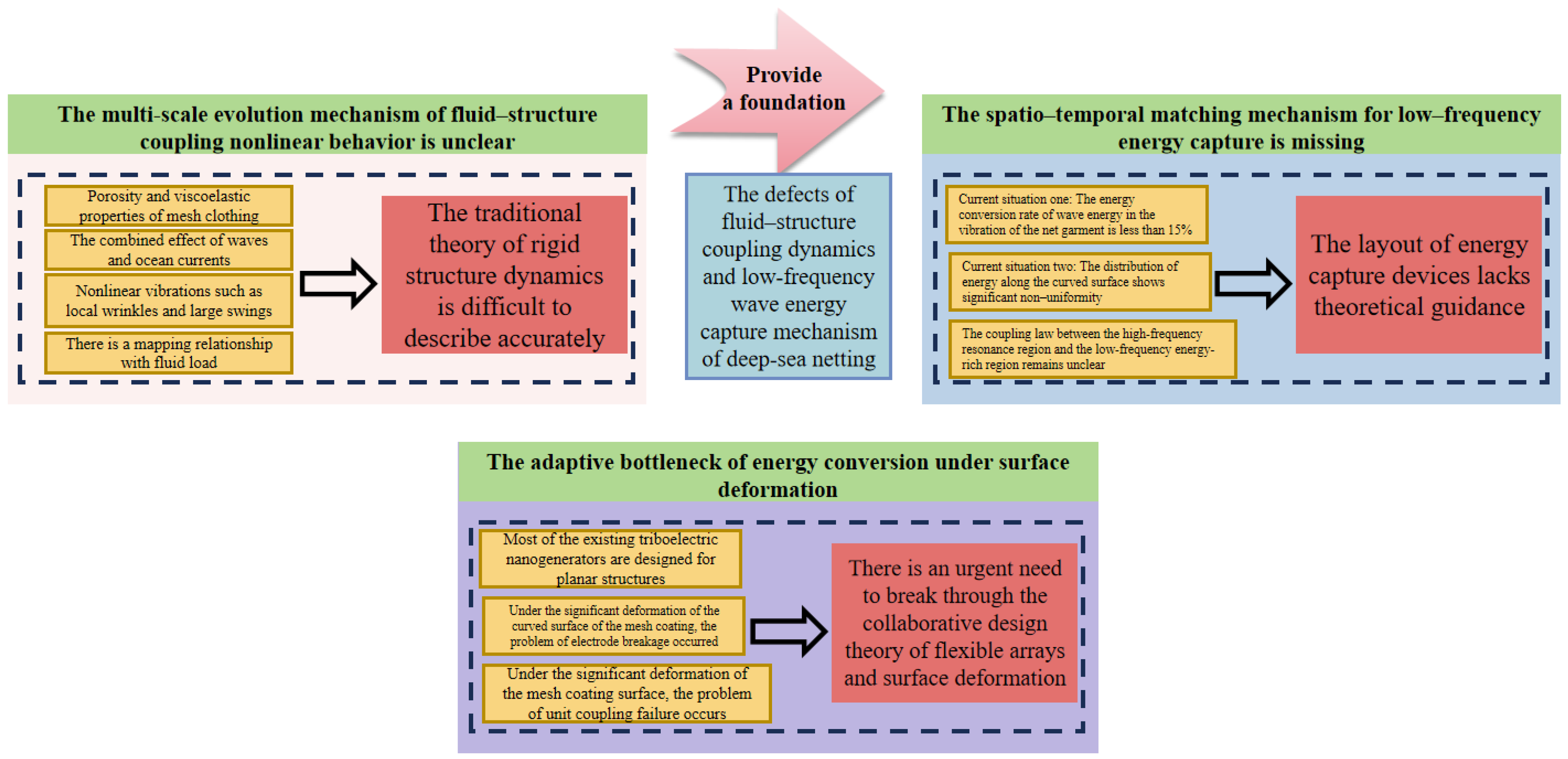
Deep-sea large-scale cages, as core equipment for deep-sea and far-sea aquaculture and resource development, face extreme fluid–solid coupling loads in complex Marine environments due to their flexible net jacket structure [26,27,28,29,30]. The efficient capture of low-frequency wave energy is the key bottleneck for realizing the self-powered sensing system of the cages. Current research mostly focuses on the high-frequency vibration response and intensity verification of the mesh structure but lacks a systematic understanding of the large nonlinear motion induced by low-frequency waves and its energy capture mechanism, which is specifically manifested as shown in Figure 2:
  • The multi-scale evolution mechanism of fluid–structure coupling nonlinear behavior is unclear: the nonlinear vibrations such as local wrinkles and large swings caused by the porosity and viscoelastic properties of the mesh fabric under the combined action of waves and ocean currents are significantly affected by the scale effect in terms of the mapping relationship between the amplitude, frequency, and fluid load. The traditional rigid structure dynamics theory is difficult to accurately describe the coupling process of “fluid-induced deformation and load redistribution” of flexible mesh fabrics.
  • The spatio-temporal matching mechanism for low-frequency energy capture is missing: the energy conversion rate of wave energy in the vibration of the mesh jacket is less than 15%, and the distribution of energy along the curved surface shows significant non-uniformity. The coupling effect law between the high-frequency resonance region (such as the edge of the mesh jacket) and the low-frequency energy-rich region (such as the center of the mesh jacket) is not yet clear, resulting in a lack of theoretical guidance for the layout of the energy capture device.
  • The adaptive bottleneck of energy conversion under surface deformation: the existing triboelectric nanogenerators are mostly designed for planar structures. Under the significant deformation of the mesh coating surface, problems such as electrode fracture and unit coupling failure are prone to occur. Moreover, the seawater corrosion resistance life of the TENG materials is mostly between 6 and 12 months. There is an urgent need to break through the collaborative design theory of flexible arrays and surface deformation.
Therefore, the research content of the second part also revolves around these three manifestations.

2.1. Nonlinear Vibration Characteristics of Net Flexible Structures Under Complex Fluid Loads

The flexible net of deep-sea cages is constantly exposed to complex fluid environments. Its nonlinear vibration characteristics under the influence of waves and ocean currents are of vital importance to the structural safety of the cages. Scholars have carried out numerical simulation studies on the force characteristics of cages under complex sea conditions. For instance, the fluid–structure interaction analysis of cylindrical sunken and floating cages, hydrodynamic calculation of disk-shaped cages, etc. However, the verification of actual sea conditions still faces high costs and technical bottlenecks [31,32]. Zhang et al. [33] conducted a dynamic coupling analysis on a wave energy converter equipped with a floating-point absorber and catchain mooring. Based on potential flow theory and rigid body dynamics, they consider the six-degrees-of-freedom motion of a floating body under wave excitation, focusing on depicting the energy exchange process between the floating body and the waves, as well as the driving characteristics of the floating body’s motion on the energy capture device. And they adopted the Catenary Theory to model an elastic and quasi-static catenary. In the local Cartesian coordinate system, the shape of the catchain can be explained by the parametric equation:
x = a u + b s i n h ( u ) + α ( 12 )
y = a c o s h ( u ) + b 2 s i n h 2 ( u ) + β ( 13 )
where a = c λ 0 g , b = c a D L e q , c = λ 0 L e q g sinh ( u 2 ) sinh ( u 1 ) .
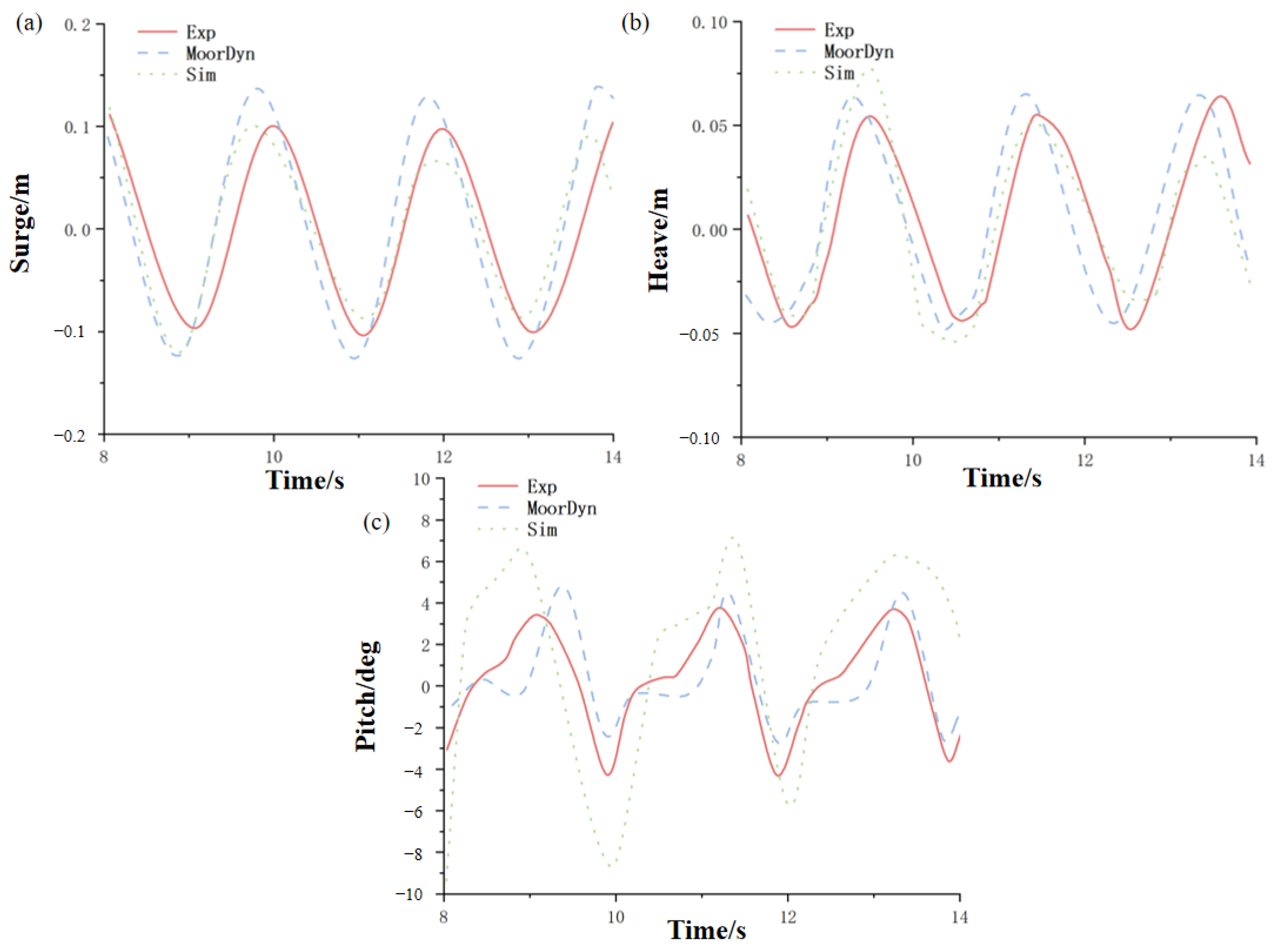
By conducting a simulation analysis on this model, they were able to determine the influence of the mass, stiffness of the mooring chain, and the Marine environment on its forces. As shown in Figure 3, the sagging and undulating movements of the floating body under the action of waves will cause changes in the length and sag of the mooring chain, which, in turn, will trigger fluctuations in mooring tension. The change in mooring tension will generate a counterforce constraining the excessive movement of the floating body and forming a closed-loop coupling of “motion—tension—motion”. These provide new ideas and methods for the dynamic study of cage systems in wave environments, which is conducive to a deeper understanding of the response characteristics of cages in similar complex, dynamic Marine environments. Not only that, they also conducted a bibliometric analysis on the progress and trends of global Marine ranching research [34], providing a macroscopic research direction reference for the study of multi-field coupling dynamic mechanisms of large-scale deep-sea cages. This can help researchers grasp the overall development context of this field, understand research hotspots and blind spots, and thus carry out related research more specifically. In addition, the team [35] studied the dynamic characteristics and fracture failure of the rigid truss trawl system during the towing process. Their research methods and analysis ideas for the mechanical properties of the structure can provide references for the study of the structural strength and stability of large deep-sea cages under complex sea conditions.
In deep-sea environments, the net garment, as a key structural component, is constantly subjected to the action of complex fluid loads. The periodic undulations of waves, the directional flow of ocean currents, and their combined effects make the vibration behavior of the net garment extremely complex [36,37,38,39,40], as shown in Figure 4. Therefore, it is a necessary project to study the nonlinear vibration characteristics of flexible mesh structures under complex fluid loads.

2.1.1. Construction of Multi-Factor Fluid–Structure Coupling Dynamics Model

Based on the fluid dynamics theory of porous media, a bidirectional coupling model of pore seepage and structural deformation is established. Focus on breaking through the following key technologies:
  • A dynamic porosity model with spatial heterogeneity was constructed using the Brinkman–Darcy equation:
μ 2 u μ K u + ρ ( u · ) u = p + ρ g
Among them, u is the seepage velocity vector of the fluid, μ is the dynamic viscosity of the fluid, K is the permeability of the porous medium, ρ is the density of the fluid, P is the fluid pressure, g is the gravitational acceleration vector, 2 is the Laplacian operator, and is the gradient operator.
The influence of the porosity gradient distribution on fluid permeation resistance is characterized by this equation, and the quantitative relationship between the time-varying characteristics of porosity and the frequency of vortex shedding is established.
2.
Introduce the fractional-order Burgers viscoelastic constitutive model, describe the frequency-dependent characteristics of the material through Caputo fractional-order derivatives, and construct a nonlinear constitutive equation considering the historical effects of strain:
σ ( t ) = η t K ( t τ ) ε ¨ ( τ ) d τ + E t K ( t τ ) ε ˙ ( τ ) d τ + η f D t α t K ( t τ ) ε ˙ ( τ ) d τ
Here, σ ( t ) represents the stress the material is subjected to at time t, η is the viscosity coefficient, E is the elastic modulus, and η f is the coefficient related to fractional viscosity.
3.
Develop a fluid–structure coupling solver based on the immersion boundary method to achieve a precise solution of the bidirectional coupling of flow field and structure under large deformation conditions.

2.1.2. Research on Nonlinear Vibration Evolution Mechanism in Complex Flow Fields

Establish a wave–current combined action test system, integrating PIV flow field measurement and DIC full-field strain measurement technology, and conduct systematic research:
1.
Multimodal coupling vibration characteristics: Analyze the nonlinear phenomena such as parametric resonance and internal resonance of the mesh structure under the coupling action of regular waves, irregular waves, and shear flow;
2.
Instability critical criterion: A periodic disturbance stability analysis framework is established through Floquet theory to determine the critical conditions for the transformation of the structure from steady-state vibration to chaotic motion under different flow velocity ratios. The vibration system of the net garment under the combined action of waves and the current is regarded as a system of periodic linear differential equations, and its dynamic equation can be expressed as follows:
x ˙ ( t ) = A ( t ) x ( t )
Among them, x(t) represents the vibration state vector of the net garment (including key parameters such as displacement and velocity), A(t) is the period coefficient matrix, and period T corresponds to the characteristic period of waves or ocean currents.
According to Floquet’s fundamental theorem, the fundamental solution matrix ϕ ( t ) of the net garment vibration system is constructed:
ϕ ( t + T ) = ϕ ( t ) C
The Floquet multiplier μ 1 , μ 2 , …, μ n is obtained by solving the eigenvalues of the matrix. As shown in Table 1, this demonstrates the relationship between Floquet multiplier modulus values and the vibration state of the net.
3.
Local fold evolution law: Based on the curvature mode decomposition method, the central difference method is used to calculate the curvature modes of each measurement point of the net garment:
κ ( x j ) ϕ ( x j + 1 ) 2 ϕ ( x j ) + ϕ ( x j 1 ) h 2
Here, ϕ ( x ) represents the displacement mode. Then, obtain the curvature mode through the second derivative:
κ ( x ) = d 2 S ( x ) d x 2
Thus, a correlation model between the two is established to quantify the associated parameters, such as the offset and distance between the initial position of the fold and the direction to the vortex core, and to reveal the influential mechanism of fold expansion on the overall damping characteristics of the structure.

2.1.3. Intelligent Mapping Model of Vibration Response and Load Characteristics

Build a multi-parameter coupled database and develop an intelligent analysis method driven by data and models:
  • The random forest algorithm is adopted to rank the importance of features, and a vibration amplitude prediction model based on XGBoost is constructed to achieve the prediction of the probability distribution of response extremum. The vibration response of the net garment under the combined action of waves and the current shows significant nonlinearity (such as local wrinkles and large swings), and there is a complex coupling relationship between its vibration amplitude and fluid load as well as structural parameters. XGBoost is based on the iterative optimization logic of gradient boosting trees (GBDT). By constructing regression trees one by one to minimize prediction errors, it can efficiently fit the nonlinear mapping relationship between multiple factors and vibration amplitudes. Compared with traditional linear models that cannot capture nonlinear features such as a “sudden increase in flow velocity causing sudden changes in vibration amplitude”, XGBoost uses a “residual compensation” mechanism. Each new tree corrects the prediction error of the previous model in each round, and the final integrated strong learner can accurately depict the dynamic evolution law of the net garment vibration.
  • Develop a convolutional long short-term memory network, integrate flow field time series data with structural response signals, and establish an end-to-end vibration state prediction framework.

2.2. Spatiotemporal Distribution Characteristics of Wave-Induced Net Motion Energy

An in-depth study of the energy spatio-temporal distribution characteristics of wave-induced net garment movement, on the one hand, can accurately quantify the energy conversion rate of wave energy in the vibration of the net garment, which is conducive to evaluating the feasibility and efficiency of the net garment as an energy capture carrier. On the other hand, it can clearly analyze the spatio-temporal distribution law of energy along the surface of the net coating, providing a scientific basis for the reasonable layout of energy capture devices, thereby enhancing the energy collection capacity of the entire system and promoting the development of deep-sea self-energy supply technology.

2.2.1. Quantitative Model of Multimodal Energy Conversion Efficiency

By comprehensively applying the linear wave theory, Hamilton’s principle, and the knowledge of fluid–structure interaction dynamics, an energy conservation equation considering multiple factors is established. Innovatively construct a time-varying energy conservation equation based on the improved Hamilton principle:
E t + · S = i = 1 n Q i
Here, E represents the total energy density of the system, S is the energy flow vector, and Qi characterizes pore dissipation.

2.2.2. Analysis of Topological Characteristics of Energy Spatio-Temporal Distribution

By adopting advanced energy analysis methods, the net garment is divided into multiple characteristic regions, and the process of energy transfer and conversion between different regions is deeply studied. Based on the energy field reconstruction method of eigen-orthogonal decomposition, the energy density distribution function is established:
Ψ ( x , y , t ) = k = 1 m a k ( t ) Φ k ( x , y )
A three-dimensional energy cloud map database is constructed through high spatiotemporal resolution measurement.

2.2.3. The Correlation Mechanism Between Resonance Modes and Energy Accumulation

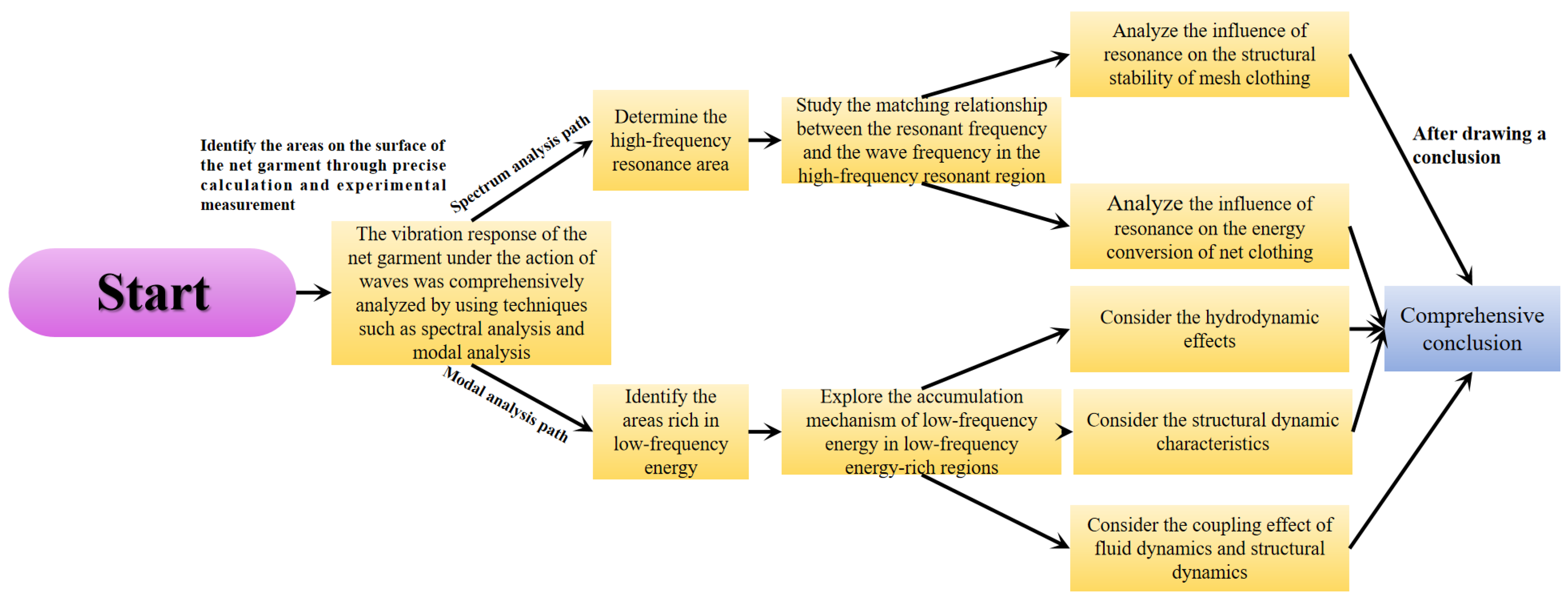
As shown in Figure 5, a comprehensive analysis of the vibration response of the net garment under the action of waves was conducted by using technical means such as spectral analysis and modal analysis. Through precise calculation and experimental measurement, the high-frequency resonance areas and low-frequency energy-rich areas on the surface of the net garment are identified. For the high-frequency resonance region, study the matching relationship between its resonance frequency and wave frequency, and analyze the influence of resonance on the structural stability and energy conversion of the mesh jacket. For low-frequency energy-rich regions, an in-depth exploration of the accumulation mechanism of low-frequency energy in this area is conducted, including fluid dynamic effects, structural dynamic characteristics, and the coupling effect between the two.

2.3. Design of Curved Surface-Adaptive TENG Arrays

As a new type of energy conversion device, TENG has broad application prospects in the field of deep-sea energy collection. A team from Chongqing University [41] has developed a TENG with an energy conversion efficiency of 48% and a durability of 500,000 cycles through interface lubrication and voltage dispersion design, which can be applied to Marine environment monitoring and data acquisition [42,43]. Shanghai University [44] proposed an electromagnetic–triboelectric hybrid generator, achieving wideband fluid energy harvesting and wireless sensing integration. The team from Beijing Institute of Technology [45] integrated TENG into the bearings of wind turbines to achieve self-power supply fault diagnosis (with an accuracy rate of 95.6%), providing a reference for the mechanical structure health monitoring of deep-sea cages. Not only that, in the latest research in 2024, the research article proposed a self-powered wireless sensing system based on human body antennas, supporting 8 m signal transmission, which is suitable for extreme environment monitoring [46]. In addition, Wang Wei et al. studied the performance of liquid–solid triboelectric nanogenerators based on multiphase liquids [47], the research progress of triboelectric nanogenerator technology in wave energy collection [48], and the research progress of fluid energy collection based on triboelectric nanogenerators [49]. However, as mentioned above, the development of TENG was not perfect. If TENG is to be widely applied in fields such as ocean energy collection (such as wave energy) and power supply for underwater sensors, it is necessary to enhance its stability in seawater environments by modifying the materials and designing the structure of TENG.
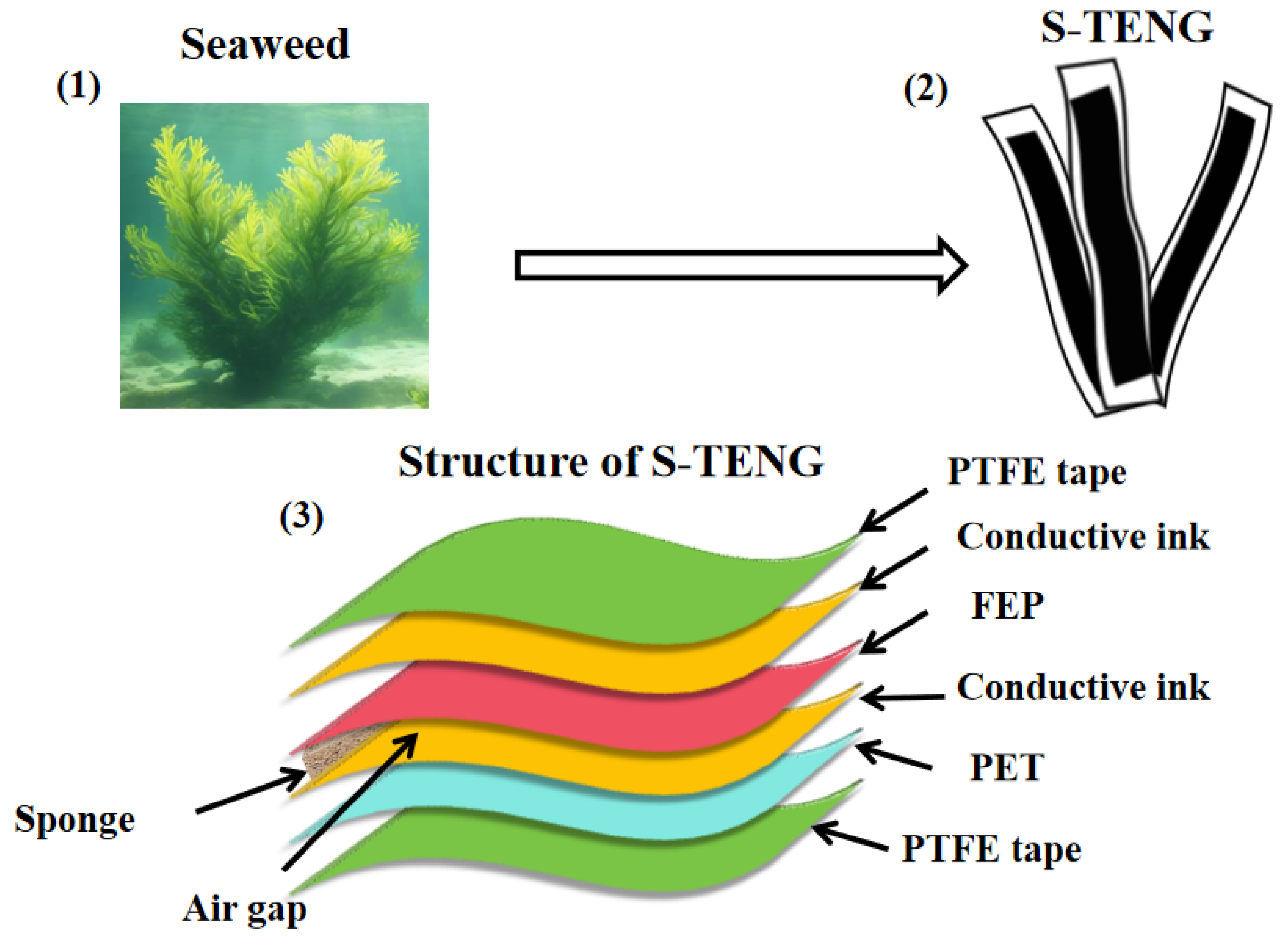
In deep-sea cage systems, achieving the efficient capture of low-frequency wave energy and conversion of electrical energy is crucial for solving the problem of self-power supply. TENG has become a research hotspot in this field due to its advantages such as simple structure, ability to convert low-frequency energy, and strong adaptability [50,51]. The design of a surface-adaptive TENG array enables the TENG to perfectly fit the surface of the net jacket, maintaining a stable and efficient energy conversion performance even when subjected to tensile, bending, and other deformations. This is of crucial significance for enhancing the reliability and practicality of the self-energy supply system in deep-sea cages and is expected to break through the bottlenecks of existing self-energy supply technologies. It also promotes the sustainable development of deep-sea aquaculture and related Marine industries. For instance, in order to reduce the manufacturing cost of TENG while significantly enhancing the stability and energy conversion efficiency of the equipment in the Marine environment, Kefan Yang [48] designed a flexible structure TENG inspired by seaweed in nature (as shown in Figure 6). The “flexibility” of this device is not only reflected in the physical ductility of the material itself but also in the design logic that adapts to the environment. In this way, the equipment can maintain stable operation in complex Marine scenarios.
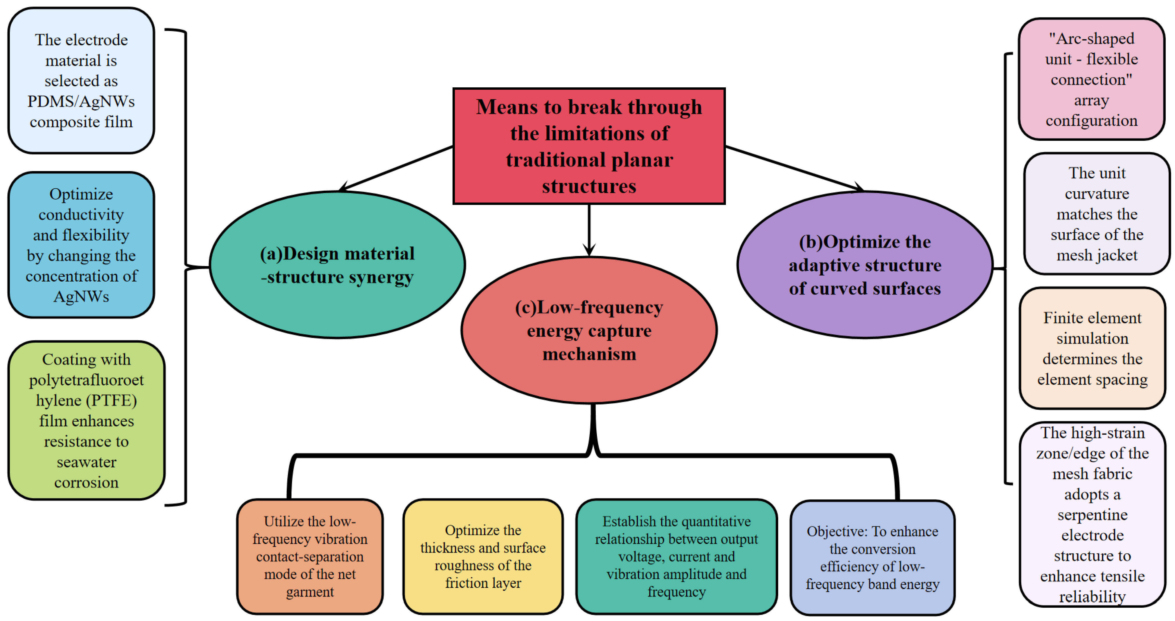
In this paper, a dynamic, adaptive, flexible TENG array is designed for the curved surface deformation of mesh clothing to break through the limitations of traditional planar structures, as shown in Figure 7.
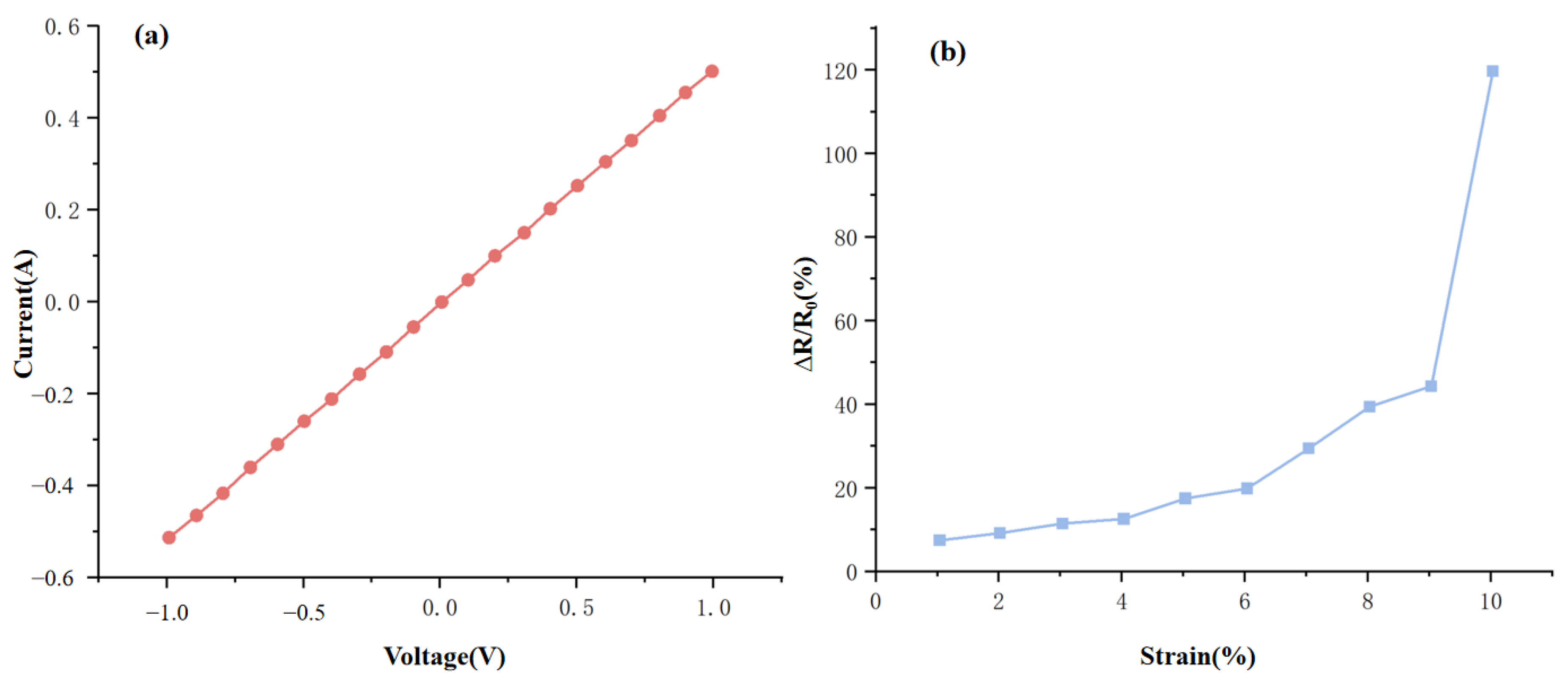
This design selects PDMS/AgNWs composite film as the electrode material and optimizes the conductivity and flexibility by changing the concentration of AgNWs. Meanwhile, polytetrafluoroethylene (PTFE) film is coated on the surface. From the perspective of material properties, PDMS itself possesses excellent flexibility and chemical stability, while AgNWs (silver nanowires) have outstanding electrical conductivity. The PDMS/AgNWs composite film formed by the combination of the two can maintain good electrical conductivity while meeting the flexibility requirements for the deformation of the mesh surface. Lay a material foundation for the stable operation of the array in a dynamic curved surface environment. Ji Chao [52] demonstrated through research that, when preparing the flexible acoustic sensor based on PDMS-AgNWs, the material prepared by combining the two exhibited high electrical conductivity, high flexibility, and good stability and could respond quickly to acoustic wave signals. As shown in Figure 8, the volt–ampere curve of the flexible stress sensor of PDMS-AgNWs is presented.
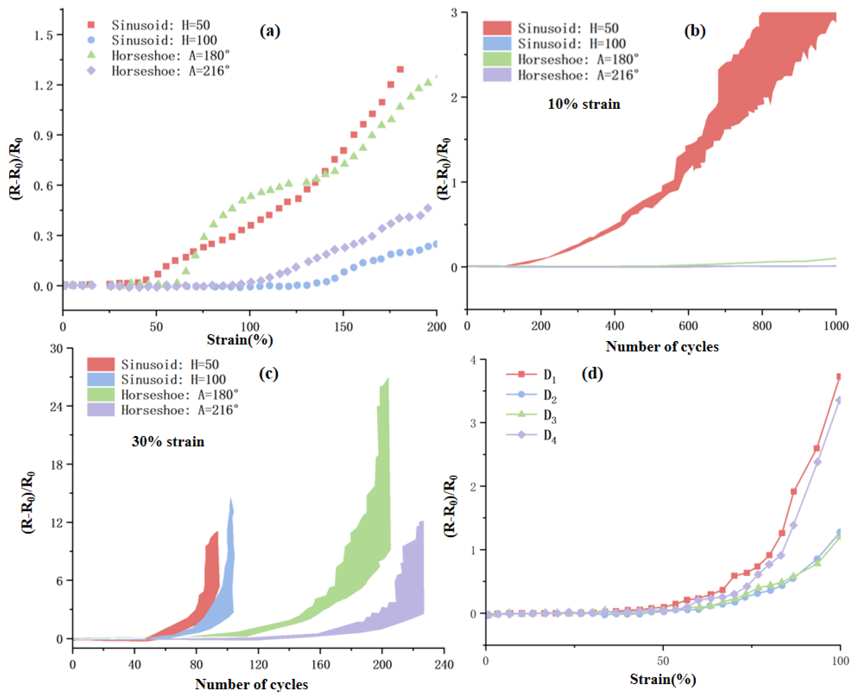
The coating design of PTFE film specifically addresses the issue of material loss in humid and corrosive environments such as the ocean. PTFE material, due to its extremely strong chemical inertness and corrosion resistance, can effectively prevent seawater from eroding electrode materials. It is often used in the chemical industry for anti-corrosion linings and sealing gaskets, effectively protecting equipment from the damage of highly corrosive media [53]. For the areas prone to high strain when the mesh fabric deforms (such as the edges of the mesh fabric), a serpentine electrode structure is designed. During the stretching process, the serpentine structure can buffer the strain force through the expansion of its own shape, preventing the electrode from breaking or the decline of electrical conductivity due to direct stretching. This significantly enhances the structural stability and operational reliability of the array in the dynamic deformation scenarios of the mesh jacket, meeting the design requirements of “improving stretching reliability and adapting to the curved surface deformation of the mesh jacket”. In 2023, among the related electrodes developed by the Printed Electronics team of the Suzhou Institute of Nano-Tech and Nano-Bionics, Chinese Academy of Sciences [54], as shown in Figure 9, the horseshoe-shaped structure with an Angle of 216° can be cycled and stretched 230 times at a tensile strength of 30%. When stretched simultaneously in four different directions, it also exhibits excellent electrical conductivity. At a tensile strength of 50%, the resistance in all directions remains almost constant (as shown in Figure 9). The serpentine electrode structure of this design can also effectively cope with tensile conditions and can guarantee the performance of the equipment in high-strain environments.
In addition to the curved surface-adaptive TENG array, electromagnetic power generation devices, piezoelectric energy collectors, and bionic integrated power generation systems have also shown application potential in the self-energy supply monitoring of deep-sea cages due to their excellent Marine environment tolerance and multimodal energy capture capabilities. To clarify the optimal application scenarios of various types of equipment in deep-sea cages, based on indicators such as energy capture frequency, power density, and environmental tolerance, this paper establishes a comparison model, as shown in Table 2, through the extensive literature comparison.

2.4. Quantitative Analysis of Power Demand for Core Equipment in Deep-Sea Aquaculture Systems

To verify the adaptability of the TENG array as a self-powered solution, it is necessary to first clarify the power consumption characteristics of each key device in the deep-sea aquaculture system. Based on the existing deep-sea aquaculture engineering cases and technical sensor parameters, a database of the equipment power demand (as shown in Table 3) was constructed to provide a quantitative basis for the subsequent selection of energy capture technology.
From this, it is not difficult to find that, in Table 3, the power consumption characteristics and power supply requirements of different devices vary significantly, specifically manifested in three types of patterns. Low-power devices dominate the core monitoring function. The total average power consumption of their structure and environmental sensors is approximately 1.4–2.2 Wh/day, accounting for only 8–12% of the system’s total power consumption. However, as 30–50 sensors need to be networked, distributed power supply must be adopted. High-power consumption devices rely on instantaneous power supply. The instantaneous power of actuating devices such as automatic feeders and water quality regulating pumps can reach 10–30 W. Although they work for only 0.5–1 h per day, their average power consumption still accounts for over 80%, and they need to be used in conjunction with energy storage modules. Meanwhile, over 90% of the equipment within the system operates in an intermittent mode of “sampling/work—sleep”, with a distinct “low power period”, which provides a necessary time window for the energy collection and storage of the TENG array.
Based on the power demand data in Table 3, this paper quantitatively compares the surface-adaptive TENG array with mainstream energy capture technologies such as solar energy, piezoelectric energy, and electromagnetic energy from three dimensions: “power matching degree—environmental adaptability—cost-effectiveness”, thereby clarifying the core advantages of TENG.
Based on the multi-dimensional data analysis and comprehensive consideration in Table 3 and Table 4, it is found that TENG technology has three core adaptation advantages in deep-sea net clothing applications, which can effectively solve the pain points of existing power supply solutions. In terms of precise power demand matching, the energy conversion efficiency of its array in the 0.1–10 Hz frequency band reaches 15–20%, which can precisely cover the main vibration frequency band of 0.5–5 Hz for deep-sea net clothing. The daily output energy of a single array (with an area of 100 cm2) is approximately 1.44–3.6 Wh, which can meet the continuous power supply requirements of 15–20 sensors. When paired with a supercapacitor of 1 F capacity, it can also store energy to supply power to instantaneous high-power equipment such as automatic feeders. In terms of environmental adaptability, the design of the PDMS/AgNWs composite membrane and PTFE coating can withstand pressure at a water depth of 1500 m and seawater corrosion for 6 to 12 months without the need for frequent maintenance, thus solving the problem of the “difficult maintenance and high cost” of deep-sea equipment. In terms of power supply layout, the TENG array supports modular deployment in different areas of the mesh jacket and can directly supply power to nearby sensors, avoiding the problems of “difficult wiring and easy damage” in traditional wired power supply and significantly reducing system complexity.

3. Energy Transfer and Cooperative Capture of Multi-Body Coupling Cage Systems Under Combined Wind–Wave–Current Actions

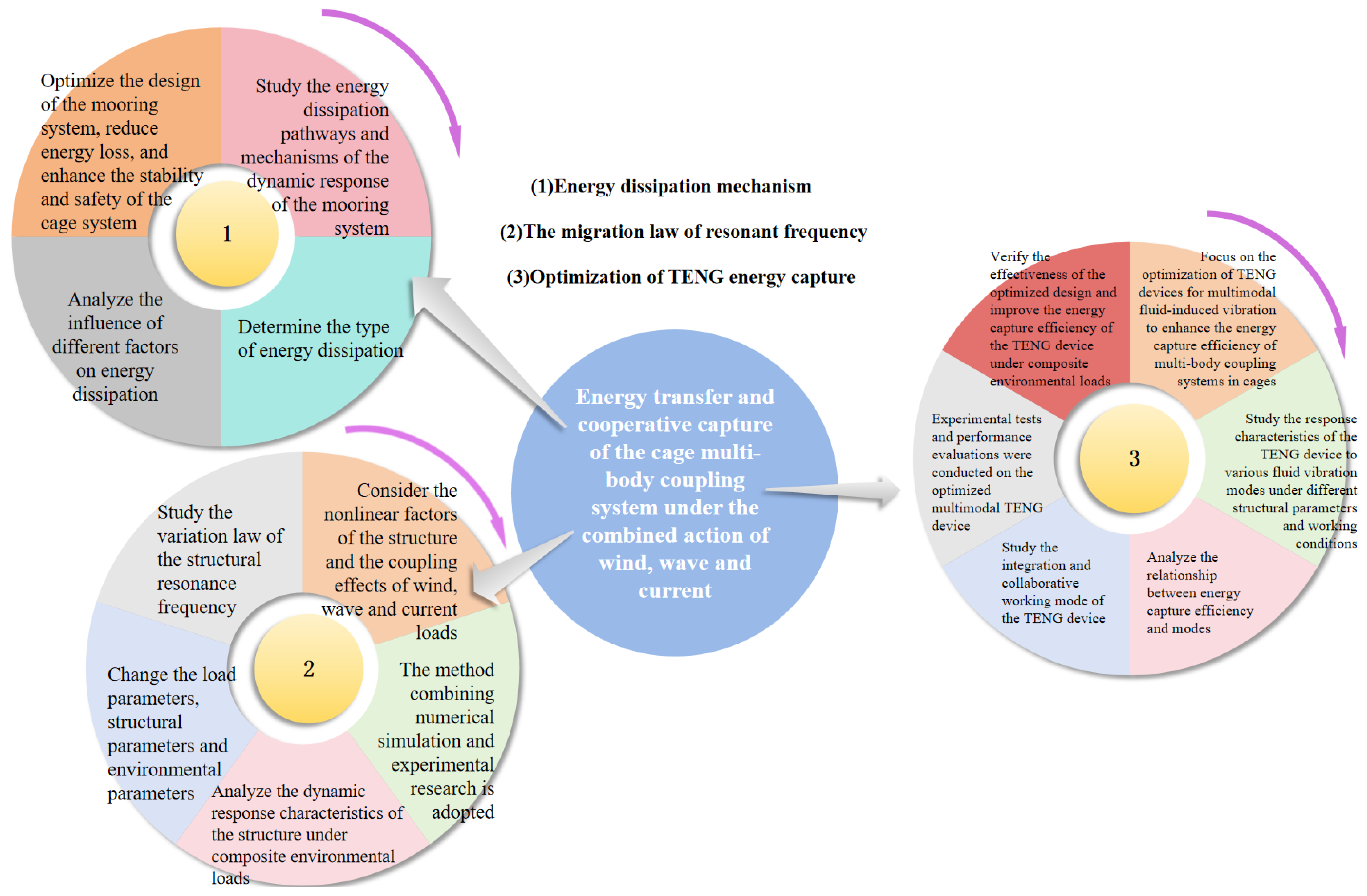
As shown in Figure 10, based on the energy flow logic of the multi-body coupling system of the cage, this paper systematically reviews the research progress in recent years from three dimensions, energy dissipation, frequency response, and energy capture, analyzes the advantages and limitations of different research methods, and finally proposes future research directions, providing theoretical support for the optimal design and engineering application of deep-sea cage systems.

3.1. Energy Dissipation Mechanism of Dynamic Response of Multi-Degrees-of-Freedom Mooring Systems

This paper studies the energy dissipation pathways and mechanisms in the dynamic response process of the mooring system through energy analysis methods. Energy dissipation mainly includes internal friction dissipation of the mooring line material, viscous friction dissipation with seawater, and collision dissipation with the seabed, etc. [55,56,57,58,59]. Analyze the influence of different factors on energy dissipation, such as the material properties, length, diameter, and pretension of the mooring line, as well as sea conditions, etc. Through research on the energy dissipation mechanism, theoretical guidance is provided for optimizing the design of the mooring system, reducing unnecessary energy loss, and improving the stability and safety of the cage system.

3.1.1. Internal Friction Dissipation of the Mooring Line Material

The viscoelastic properties of mooring line materials are the core source of internal friction dissipation, and the degree of energy loss can be quantitatively described by the loss factor (tanδ). Consider polyester (PET), a commonly used synthetic fiber material, which has become one of the mainstream materials for deep-sea cage mooring systems due to its excellent tensile strength, low elongation, and resistance to seawater corrosion. This paper will start from the viscoelastic characteristics of polyester materials [60] and, in combination with relevant research, systematically expound the internal friction dissipation mechanism of anchor line materials under dynamic loads.
In the field of Marine engineering, the application of polyester materials can be traced back to earlier mooring system practices. For example, as Michel Francois and Peter Davies [61] pointed out at the 27th ASME International Conference on Marine Mechanics and Arctic Engineering (OMAE2008) in 2008, polyester has been maturely applied in floating platform mooring systems in the offshore areas of Brazil (for over 10 years), West Africa, the Gulf of Mexico, and other regions, and its stability under long-term loads has been verified by engineering. From the perspective of material structure, the molecular structure of polyester fibers contains a large number of ester functional groups, which endows the material with a relatively high modulus and strength but also makes it exhibit certain viscoelastic characteristics. The specific manifestation of this viscoelastic characteristic under dynamic loading can be further explained by the polyester rope load-elongation model proposed by Francois and Davies.
  • Through three-parameter fitting, they wrote the elongation L(t) on each creep (or recovery) platform as follows:
L ( t ) = L t p + a c · l o g 1 + t t p t a
This fitting (for a c , t a , and L ( t p ) ) is independent of the time unit and the starting point, and its result does not depend on the selection of t p (i.e., the time at any point on the load platform).
2.
In L(t), they use
L τ L t p + a c · l o g τ / t a
It is used to represent the elongation L τ at the end of each 1 2 period of duration τ .
3.
Then, the linearized quasi-stiffness is regarded as the secant stiffness between the last consecutive 1 2 period (duration τ ) endpoints. The load is normalized through the rope MBS to obtain the dimensionless quasi-static stiffness KrS.
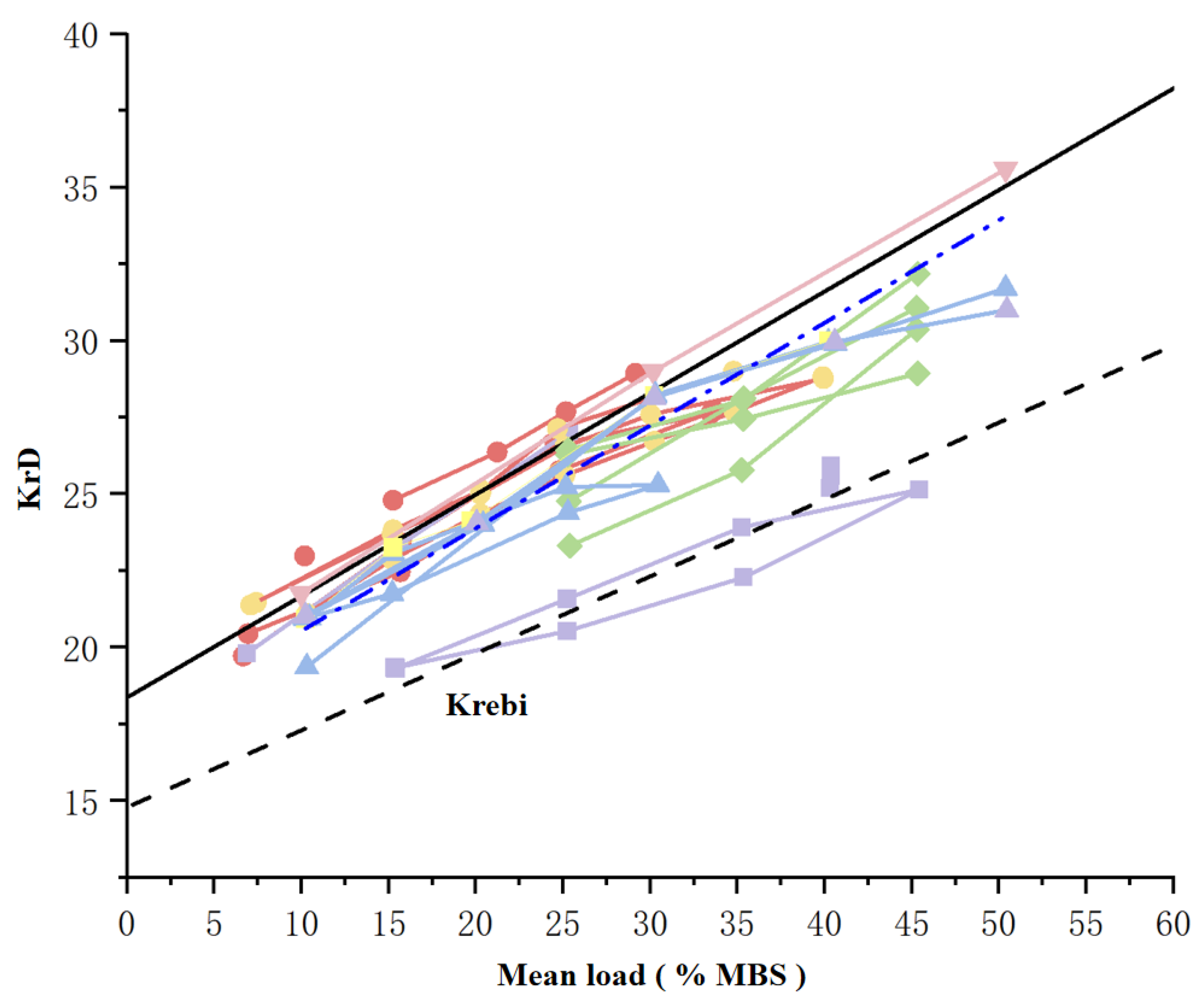
This model decomposes the response of polyester rope into average elongation, quasi-static response, and dynamic response. Among them, the dynamic response corresponds to the cyclic loads (low frequency and wave frequency) caused by the wind, waves and currents, and its mechanical behavior needs to be quantified by dynamic stiffness (KrD). The essence of dynamic stiffness is precisely the macroscopic manifestation of the viscoelasticity of materials under cyclic loading—this is highly consistent with the physical mechanism of internal friction dissipation; that is, energy loss occurs in materials during dynamic deformation due to molecular chain movement, interface friction, etc. In Marine environments, polyester mooring lines are constantly subjected to cyclic loads, and their dynamic mechanical properties have a significant impact on the stability and service life of the mooring system. As shown in Figure 11, Francois and Davies experimentally verified that the dynamic stiffness (KrD) of the polyester rope is mainly controlled by the average load, and under actual random loads (such as wideband signals simulating Marine environments), its load-elongation relationship is close to linear. Meanwhile, the correlation between energy loss and load frequency is relatively weak (stiffness variation is only 1.4% within a period of 12.5 s to 500 s). This conclusion provides engineering background support for subsequent experimental research; that is, the internal friction dissipation characteristics of polyester mooring lines need to be analyzed in combination with actual load conditions.
From a further perspective of the mesoscopic characteristics of dynamic mechanical behavior, polyester materials exhibit obvious frequency and temperature dependence. This phenomenon is widespread in different types of polyester materials. For instance, Liu Xiu et al. [62] found in their 2024 research that in the frequency scanning test of PET materials, at the same temperature, the energy storage modulus gradually increased with the increase in the test frequency, showing a trend of enhanced rigidity. The loss factor, near the glass transition temperature, first increases and then decreases with the increase in frequency, showing a distinct peak. This result complements the “linear increase of dynamic stiffness with average load” observed by Francois and Davies: the former reveals the influence of frequency and temperature on viscoelasticity from the molecular motion level, while the latter quantifies the regulatory effect of load conditions on dynamic mechanical properties from the engineering application level. Together, they construct a “microscopy-macro” analysis framework for the internal friction dissipation characteristics of polyester mooring lines, providing a complete mechanical basis for the material selection and life assessment of deep-sea cage mooring systems.

3.1.2. Viscous Frictional Dissipation of Seawater

The viscous friction between the mooring line and seawater is one of the main paths for energy dissipation, and its power loss can be calculated by the Morison equation:
F D = 1 2 C D ρ D | u v | ( u v )
Among them, F D represents the viscous frictional force per unit length, N/m; C D is the drag coefficient, dimensionless; ρ is the density of seawater, kg/m3; D is the diameter of the anchor line; u is the velocity of seawater, m/s; and v is the velocity of the anchor line, m/s.
Leandro S. P. da Silva [63], in the article “Statistical linearization of the Morison’s equation applied to wave energy converters”, points out that viscous drag has a significant effect on the dynamics of wave energy conversion devices in high-energy sea states and large motion caused by resonance. In this paper, the viscous resistance is derived by using the statistical linearization technique, and its equivalent linear term is decomposed into the excitation term and the damping term, providing a reliable and low-cost method for the estimation of system dynamics. This indicates that the Morrison equation has significant application value in studying the energy loss and dynamic response of Marine energy-related structures and also reflects from the side the key significance of calculating the viscous friction dissipation of seawater through this equation for understanding the performance of Marine engineering structures. According to S. Beji’s research [64], the drag force stems from convective acceleration and surface frictional resistance. Although surface frictional resistance is not explicitly expressed in the Morrison equation, it is part of the drag force. This literature derives the momentum equation expression of one-dimensional flow from the one-dimensional momentum equation:
ρ u t + ρ u u x = p x + τ y x y
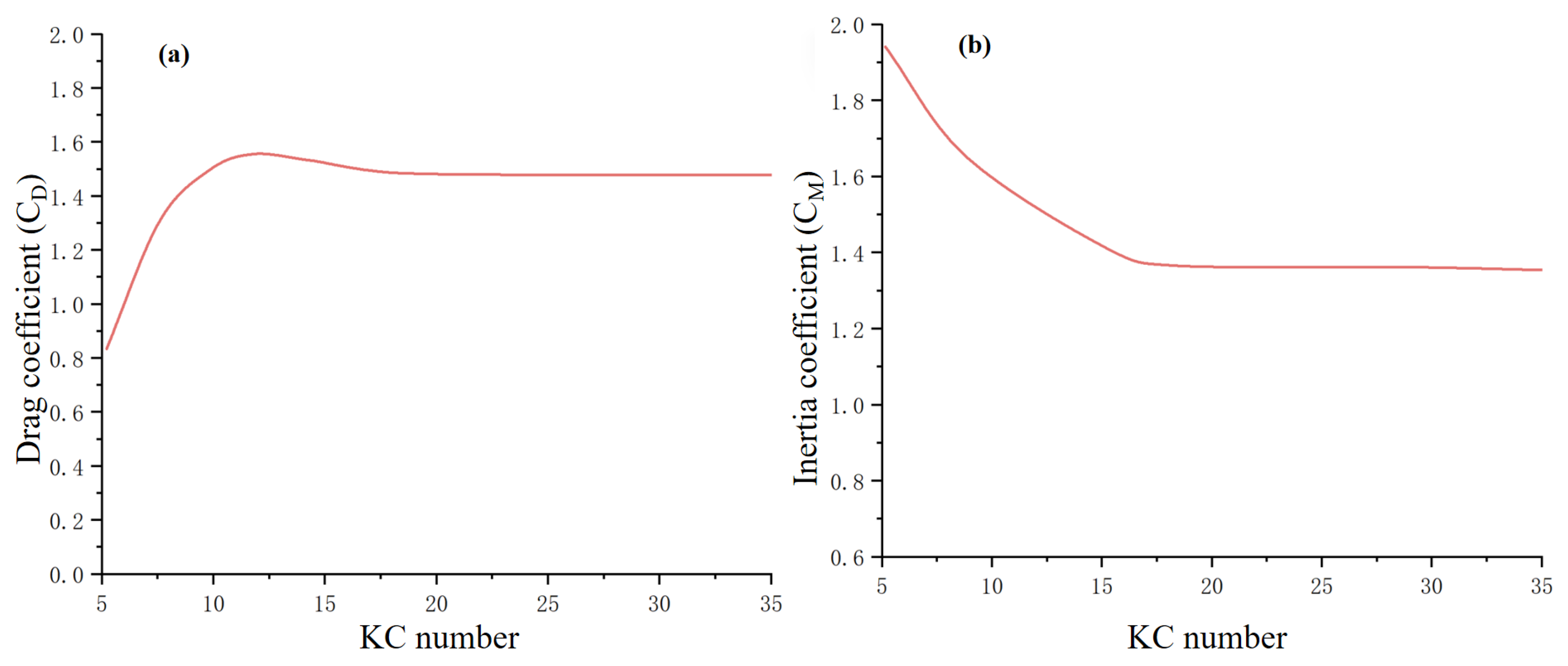
It also indicates that the Morison equation is a special case, providing a solid theoretical foundation for the Morison equation. This further indicates that when calculating the viscous frictional dissipation of seawater using the Morrison equation, the accurate understanding and calculation of the drag force are crucial for precisely assessing energy dissipation. Liu et al. [65] discovered that the key to calculating the Morrison equation lies in determining the drag force coefficient C D and the inertial force coefficient C M . Therefore, they weighted and averaged the pure wave quantity value and the pure flow value to obtain the hydrodynamic coefficient in the wave–current coexistence field:
C D = C D w u o + C D c U α u o + U α = C D w K C w + C D c K C c α K C w + K C c α = C D w + C D c V T α 1 + V T α
C M = C M w u o + C M c U α u o + U α = C M w K C w + C M c K C c α K C w + K C c α = C M w + C M c V T α 1 + V T α
In the formula, α is the weighting coefficient; C D w and C D c are determined by K C w and Re w ( Re w refers to the wave Reynolds number); and the subscript w represents the pure wave quantity. C M w and C M c are determined by Re c ( Re c refers to the Reynolds number of water flow), and the subscript c indicates the pure flow rate.
As shown in Figure 12, the drag force coefficient is affected by multiple factors such as the shape of the pile column, its placement state, the number of KC, the number of Re, and the wave and flow conditions. Liu Guijie and others summarized the research results under different conditions, such as the variation laws of coefficients when pure waves and wave–current combined effects occur, which enables more precise calculation of the viscous frictional dissipation of seawater using the Morison equation.

3.2. Migration Law of Structural Resonance Frequency Under Composite Environmental Loads

The resonance response of the cage multi-body coupling system is the main cause of its structural fatigue failure. In practical application scenarios, the combined effect of wind, waves, and the current will introduce various nonlinear factors such as geometric nonlinearity, material nonlinearity, and fluid–structure coupling nonlinearity, which will cause a significant shift in the original resonance frequency of the system [66,67,68,69,70]. Therefore, clarifying the migration law of this resonant frequency has become the core key to avoiding resonant disasters. To achieve this goal, the research should be based on the dynamic model of the multi-body coupling system of the cage. In the model, the nonlinear factors of the structure itself and the coupling effects of the wind, waves, and current loads should be fully considered. Then, a method combining numerical simulation and experimental research should be adopted to systematically analyze the dynamic response characteristics of the structure under composite environmental loads. During this process, by specifically changing the load parameters, structural parameters, and environmental parameters, the variation law of the structural resonance frequency is ultimately explored and clarified, providing theoretical and data support for resonance prevention and control.

3.2.1. The Influence of Load Parameters on Resonant Frequency

The period and wave height of the wave load are the core parameters for regulating the resonant frequency [71,72,73,74,75]. In the multi-body coupling system of the cage, the regulation effect of the wave load period and wave height on the resonant frequency needs to be analyzed in combination with the dynamic response characteristics of the system. Relevant numerical simulation studies have provided solid technical support and data verification for this regulation mechanism. From the perspective of numerical modeling of the multi-body coupling system of the cage, Shuo Mi et al. [76] proposed a Euler–Lagrangian implicit coupling model based on the OpenFOAM platform. The immersion boundary method was adopted to achieve precise coupling between the flow field and the mesh structure. Meanwhile, the mesh element was constructed through the mass-spring model, and the resistance coefficient was defined by piecewise functions. The multi-body collaborative mechanism of “net jacket—floating body—mooring” in the cage has been completely restored. When simulating different wave conditions, this study found that when the wave period approached the inherent vibration period of the cage system, the dynamic response of the system (such as the sag displacement of the floating body and the tension of the mooring rope) showed a significant increase, and the increase showed a nonlinear upward trend with the increase in wave height—this result directly confirmed the “matching trigger” effect of the wave period on the resonant frequency, and the “amplification regulation” effect of wave height on the intensity of resonance response provides a quantitative basis for the correlation law between load parameters and resonance frequency.
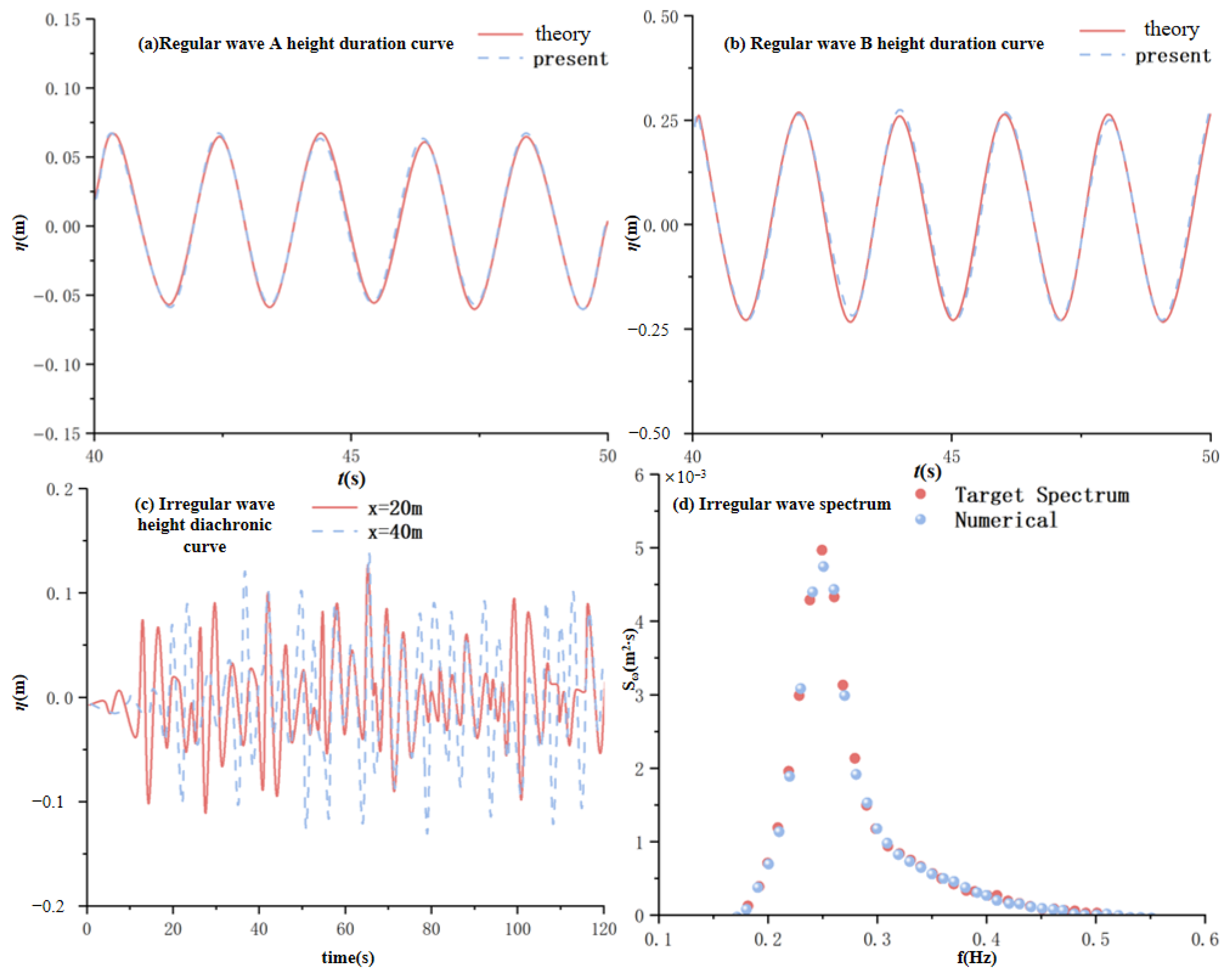
At the level of precise application and verification of wave load parameters, Cao and Wan [77] constructed a viscous numerical wave pool suitable for Marine engineering structure analysis based on the OpenFOAM platform by improving the wave generation algorithm and the design of the wave dissipation boundary:
X ( t ) = S e sin ( ω t ) H 4 d T 3 sinh 2 k d n 1 2 sin 2 ω t
Among them, S e represents the stroke calculated based on the theory of linear wave plates; n 1 = 1 2 1 + 2 k d sin 2 k d .
μ s ( x ) = α s x x 0 / L s 2 , x > x 0 0 , x x 0
For this formula, x 0 represents the starting position of the cancelation zone; L s represents the length of the wave cancelation zone; and α s is a dimensionless artificial viscosity coefficient used to control the wave cancelation intensity. The larger the value of α s , the greater the corresponding wave cancelation intensity. Unlike the traditional sponge layer wave elimination methods, this paper introduces a correction velocity in the wave elimination source term f s . Its main function is to perform quality correction and ensure the conservation of mass during the calculation process.
Thus, the stable generation and precise control of regular and irregular waves have been achieved. As shown in Figure 13, the research takes the cage multi-body system as the analysis object. By comparing the resonance response characteristics of the system under different wave parameters, it is found that the numerical simulation results of waves A and B demonstrate the good computational accuracy of the Stokes second-order wave theory solution. The wave-forming boundary is given a linear wave condition but it can be seen that when the wave steepness is large, the regular wave will still undergo nonlinear evolution during propagation, and the resulting wave surface has sharp crests and relatively flat troughs.
Meanwhile, this study verified the reliability of the established OpenFOAM model in wave load transmission and system resonance response prediction by comparing the numerical simulation results with the physical model test data, further consolidating the technical foundation of the “wave period—wave height—resonance frequency” correlation analysis. It provides a numerical simulation method and data support for the resonance frequency regulation of the multi-body coupling system of the cage.

3.2.2. The Regulatory Role of Structural Parameters

Structural parameters, such as the size of the cage, the material of the frame, and the diameter of the mesh, play an important regulatory role in the resonant frequency of the multi-body coupled cage system. The mesh size and wire diameter of the net garment directly affect the stiffness characteristics of the system and thereby change the resonant frequency. This influential mechanism has been verified in the research of various engineering scenarios related to net garments. Specifically, it can be further clarified through the following research conclusions:
From the perspective of the basic mechanical properties of mesh clothing, Chen et al. [78] quantitatively analyzed the influence laws of mesh size and wire diameter on stiffness-related indicators through numerical simulation experiments. The research finds that, under the condition that other parameters remain unchanged, when the mesh size of the net garment increases, the force-bearing capacity of the net garment significantly decreases, and the corresponding equivalent stiffness also reduces accordingly. An increase in the wire diameter will enhance the structural load-bearing capacity of the mesh garment, causing the equivalent stiffness to show an upward trend. As shown in Figure 14, the quantitative relationship between the variation range of different mesh pins/wire diameters and the force and flow rate is presented.
In the application scenarios of multi-body cage systems, the research by Huang et al. [79] further confirmed this correlation. This study, focusing on the typical multi-body coupling system of the HDPE circular gravity cage, analyzed the influence of mesh size changes on the overall mechanical response of the system. It was found that an increase in mesh size can reduce the overall deformation of the cage during the force application process, indirectly reflecting the improvement of the equivalent stiffness of the system. Moreover, the quantitative change trend between mesh size and deformation was clarified. It is indicated that, in the multi-body coupling cage system, the stiffness can be regulated by optimizing the mesh size, thereby achieving the adjustment of the resonant frequency.
From the perspective of engineering practice application, the research by Chen et al. [80] emphasizes the crucial role of mesh parameters in multi-body systems. This study points out that the mesh jacket is the core component affecting the overall stiffness of the self-elevating truss box. After taking into account the action of the mesh jacket, the reaction force of the system’s pile legs and the utilization coefficient of the truss increase significantly, demonstrating the constraint effect of the mesh jacket on the overall stiffness of the system. Meanwhile, the paper provides the cluster modeling parameters corresponding to the specific mesh size. In the design of multi-body coupled cage systems, by determining parameters such as mesh size and wire diameter to precisely control stiffness and resonant frequency, it offers a reference for engineering practice.

3.2.3. Coupling Effects of Nonlinear Factors

The nonlinear factors in the multi-body coupling cage system, including geometric nonlinearity, material nonlinearity, and fluid–structure coupling nonlinearity, do not act independently but have complex coupling effects, further influencing the migration of the system’s resonant frequency. Geometric nonlinearity mainly occurs when the structure undergoes significant deformation [81]. At this point, the relationship between the stress and strain of the structure is no longer linear, thereby altering the stiffness of the structure. Material nonlinearity is caused by the inelastic properties of the material itself, such as plastic deformation and creep, and also affects the stiffness and mass distribution of the structure [82]. Fluid–structure coupling nonlinearity is due to the interaction between the fluid and the structure. The fluid load acting on the structure varies with the deformation of the structure, and the deformation of the structure is also affected by the fluid load, forming a complex coupling relationship, which cannot be ignored in the research [83]. The influence of the above-mentioned nonlinear fluid–structure coupling on the vibration frequency, strain distribution, and energy density of the net garment directly determines the structural adaptability, layout rationality, and upper limit of energy output of the TENG array, and the design parameters need to be optimized specifically.
Nonlinear fluid–structure coupling can alter the vibration characteristics of the net garment, thereby affecting the energy capture conditions of the TENG. The specific manifestations and corresponding design optimizations are as follows: large deformation of the mesh jacket can cause “contact misalignment” in traditional planar TENG cells. Finite element simulation verification shows that when the mesh jacket stretching rate reaches 15–20%, the contact area of the planar cells decreases by 30–40%, and the output power drops by more than 50%. To address this issue, the original “serpentine electrode” needs to be upgraded to a “stretchable wavy electrode”. And the matching relationship between the peak spacing of the electrode and the wrinkling wavelength of the mesh jacket was determined through COMSOL (6.2) simulation to ensure the retention rate of the contact area after deformation. The viscoelasticity of the mesh fabric material can cause a “drift” in vibration frequency. Based on the fractional Burgers model calculation, it is known that under the wave excitation of 5–10 Hz, the material hysteresis effect will reduce the actual vibration frequency by 10–15%, resulting in a mismatch with the original design frequency of TENG (0.1–10 Hz). To address this issue, a “frequency adaptive module” needs to be added to the TENG array. By increasing the thickness of the friction layer from 50 μm to 80 μm, the resonant frequency of the TENG is shifted by 12–18% towards the low frequency, thereby complementing the frequency drift caused by the nonlinearity of the material. In addition, fluid nonlinearity such as vortex-induced vibration and wave–flow coupling can cause uneven energy distribution on the surface of the mesh jacket. Through PIV experiments, it was measured that the energy density in the vortex zone at the edge of the mesh jacket (0.3–0.5 mW/cm2) is 2–3 times that in the central zone (0.1–0.2 mW/cm2). Moreover, there are instantaneous energy pulses (with a peak of up to 1.2 mW/cm2), so the layout of the TENG array needs to be optimized, dividing it into “high-energy zone units” and “conventional zone units”. The edge zone adopts a “double-layer friction structure” (PTFE + FEP) to enhance the upper limit of energy capture. The central area adopts a “lightweight unit” (PET substrate) to reduce costs. Meanwhile, an energy distribution model is established through MATLAB (R2023a), which can ultimately increase the total output of the array by 40% to 60%.

3.3. Optimization of TENG Devices for Multi-Modal Fluid-Induced Vibration

As a new type of energy harvesting device, TENG can convert the mechanical energy of fluid-induced vibration into electrical energy, providing a solution for the self-power supply of deep-sea cages [84,85,86,87,88]. Multimodal TENG can achieve significant improvements by adapting to multiple fluid vibration modes, such as the up-and-down vibration of waves and the horizontal vibration of ocean currents, including the efficiency of energy capture. Structural parameter optimization and modal adaptation are the main aspects of optimizing its design.
The structural form of TENG directly determines its response capability to different fluid vibration modes. The structural parameters of multimodal TENG have a significant impact on its modal adaptation and energy capture efficiency [89,90]. The magnitude of the vibration mass determines the natural frequency of the TENG device. Inspired by the classic Archimedes helix, Zhou et al. [91] prepared composite fibers (SMFs) with helical element structures by rolling and cold stretching a double-layer film of MXene and solid polymer electrolyte (as shown in Figure 15). This unique helical structure demonstrates significant advantages in multimodal energy harvesting. From the perspective of structural parameters, parameters such as the helical period, number of layers, and MXene content have a significant impact on its performance. When dealing with mechanical vibration modes, a reasonable helical period design can effectively disperse external stress, enabling fibers to evenly distribute stress when subjected to vibration, avoiding structural damage caused by local stress concentration, and thus ensuring the stability of energy capture. Meanwhile, the variation in MXene content will affect the electrical properties of the material, thereby altering the generation and transmission efficiency of charges during vibration, and ultimately influencing the energy capture efficiency. For humidity gradients and temperature difference modes, the ion–electron coupling device formed by the alternating layers of MXene and polymer electrolytes plays a role. An appropriate number of layer and material ratios can optimize the transport path of ions and electrons, enhance the response to humidity and temperature changes, and improve energy capture efficiency. This study, through experimental and theoretical analysis, clarified the relationship between these structural parameters and multimodal energy harvesting, providing an important basis for designing efficient multimodal energy harvesting fibers.
Jin Sun Yangyang [92] focuses on the application of drum-type TENG devices in vibration energy collection. The structural parameters of the drum TENG, such as the radius of the drum surface, the number of electrode pairs, and the electrode spacing, have a direct impact on its energy capture efficiency in the vibration mode. In the vertical contact–separation vibration mode, an increase in the number of electrode pairs can significantly enhance the output power. He experimentally measured that the output power of a single electrode pair could reach 1.32 × 10⁻⁶ W within a single cycle. When an eight-electrode pair drum TENG device was used, the output power increased to 1.06 × 10⁻⁵ W. This is because more electrode pairs increase the area of action of the triboelectric effect, enabling the generation of more charges under the same vibration conditions and thereby enhancing the energy capture efficiency. The variation in the drum surface radius and the electrode spacing will affect the natural frequency and electric field distribution of the device. If the radius of the drum surface is too large or too small, it may cause the natural frequency of the device to not match the external vibration frequency, reducing the energy capture efficiency. If the electrode spacing is inappropriate, it will affect the transfer and collection of charges and thus impact the output performance. Through finite element analysis and experimental verification, this study revealed the intrinsic connection between the structural parameters of the drum TENG and the vibration mode adaptation as well as the energy capture efficiency. Not only that, but Yang Hongbo [93] also designed a triboelectric nanogenerator with a specific structure for the low-frequency environmental energy of water waves. This further fully demonstrates the significant influence of structural parameters on the multimodal TENG in the specific mode of water wave energy harvesting.

4. Biomechanics of Interactions Between Fish Schools and Cage Flow Fields and Micro-Energy Harvesting Technology

The behavior of fish schools can serve as a “natural indicator” of the dynamic load on the cage structure, which is specifically manifested in two aspects: first, the net jacket in the area where fish schools gather will generate additional local loads due to the water flow blocking effect; second, the vortices caused by the rapid swimming of fish schools will intensify the vibration of the net jacket. All these characteristics of fish school behavior can be directly captured by fish-on-board sensors.
In the fish–cage flow field interaction system, the tail swing movement of fish is a key factor affecting the characteristics of the flow field. The periodic tail wagging of fish induces the formation of a complex vortex energy field around them. The distribution and evolution of this vortex energy field directly affect the energy exchange between fish stocks and the flow field, as well as the energy scale available for micro-energy capture [94,95,96,97]. In addition, the research and development of high-performance micro-energy sensors and management systems is an important guarantee for achieving the effective capture and utilization of micro-energy. Bionic flexible TENG sensors, with their advantages of high sensitivity, low cost, and self-driving capabilities, have demonstrated great application potential in the field of Marine micro-energy monitoring and capture. However, there are still many unsolved problems in the current research, such as the precise description of the vortex energy field induced by fish tail swinging, the improvement of the performance of bionic flexible TENG sensors in complex Marine environments, and the efficient management of multi-physics field coupled micro-energy, etc. This paper will systematically review the research progress in the above-mentioned fields, analyze the existing problems and challenges, and look forward to future research directions with the aim of promoting the in-depth development of biomechanics and micro-energy capture technology of fish–cage flow field interaction. Figure 16 shows the main content of this part of the analysis.

4.1. Characteristics of the Vortex Energy Field Induced by Fish Tail Swing Motion

The tail swing movement of fish is a typical biological movement and the main means for fish to generate propulsion and achieve movement in water. During the tail swing process, the fish tail pushes the surrounding water to form a series of vortices. These vortices carry certain energy and constitute a unique vortex energy field [98]. Studying the characteristics of this vortex energy field is the basis for understanding the interaction between fish schools and cage flow fields and developing micro-energy capture technology.

4.1.1. Experimental Study on the Characteristics of Vortex Energy Fields

In the experimental study of the vortex energy field induced by fish tail wagging movement, it is of vital importance to construct a high-precision fish swimming experimental platform. This platform needs to meet the requirements of synchronous and high-precision capture of fish swimming postures, tail fin movement parameters, and flow field vortex characteristics. The existing related experimental research has provided key references for the core technical direction and performance verification of the platform construction. Specifically, the following two representative research results can be combined for supplementary explanation:
  • The reference basis for the core measurement technology of the experimental platform:
The analysis of the energy field of the tailing-induced vortex in fish relies on advanced flow field visualization and data analysis techniques. Guo Chunyu et al. [99] achieved dynamic capture of the shedding process of the tailing-induced wake vortex pair during the linear acceleration of zebrafish based on particle image velocimetry (TR-PIV) technology and the biorthogonal decomposition (BOD) method. The evolution law of the dominant vortex structure in the flow field was precisely characterized through low-order modes. This technical approach can be directly applied to the construction of the flow field measurement module on the experimental platform, clarifying that the spatial resolution and sampling frequency of the PIV system need to match the tail swing frequency of fish (for example, the tail swing frequency of zebrafish during acceleration is approximately 5–8 Hz). Meanwhile, the effectiveness of the BOD method in extracting key features of the vortex energy field (such as vorticity intensity and vortex core position) was verified, providing experimental support for the selection of data analysis algorithms on the platform.
2.
Comparison indicators for performance verification of the experimental platform:
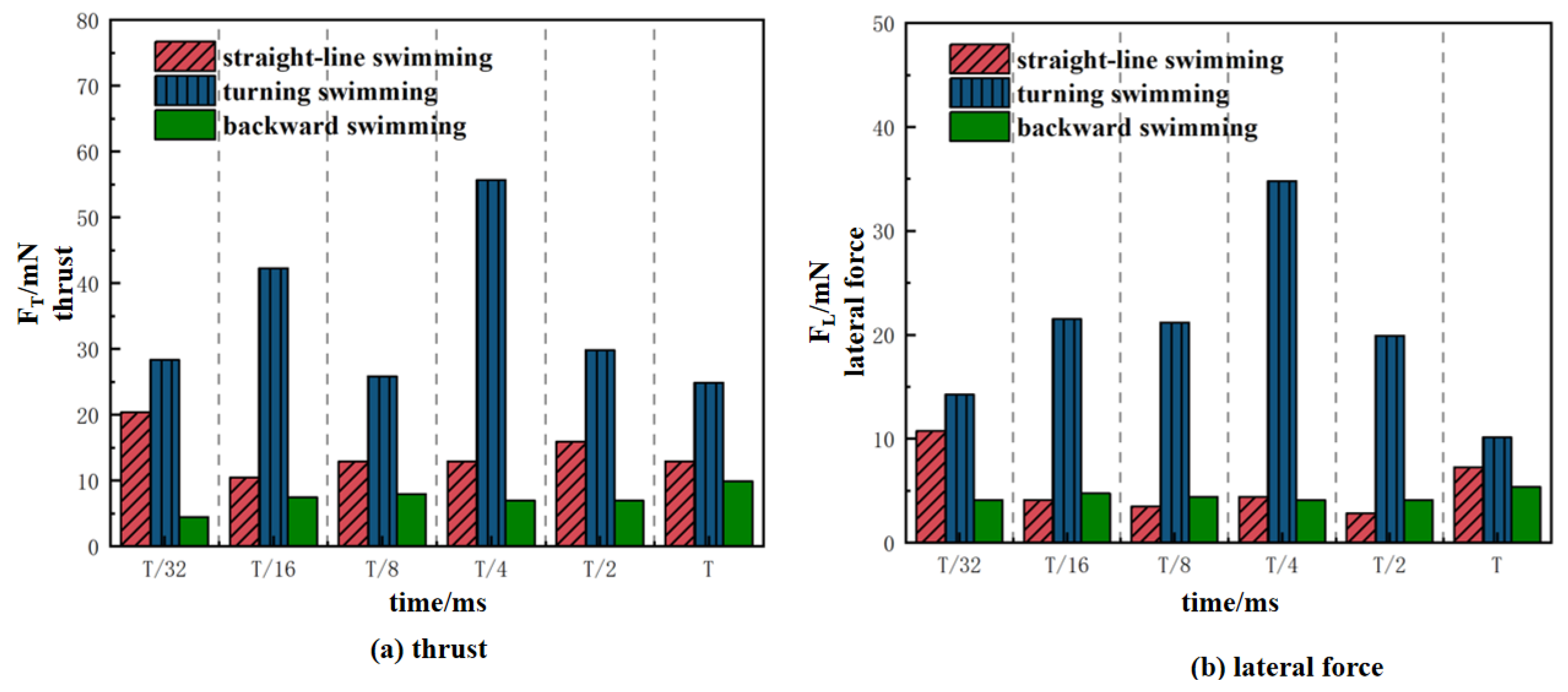
After the experimental platform is constructed, its reliability needs to be verified through tests in specific fish swimming scenarios. Yang Guodang et al. [100] provided quantitative comparison indicators under multiple swimming conditions. This study focuses on three typical postures of grass carp: straight-line swimming, turning swimming, and backward swimming. As shown in Figure 17, they measured the thrust and lateral force around the fish body under different swimming conditions through the PIV system, thereby obtaining the vortex characteristics induced by tail swing; among them, the positive vortex at the tail dominated the generation of thrust when swimming in a straight line, and when the head deflection Angle was controlled at 9–10°, the energy conversion efficiency reached the highest (83%). This result can serve as a benchmark for verifying the performance of the experimental platform. After the platform is built, herbivorous fish of the same body type (such as grass carp and crucian carp) can be selected for linear swimming tests to compare and measure the vortex distribution, thrust coefficient, and energy efficiency of the tail-induced vortex.

4.1.2. Numerical Simulation of Vortex Energy Field Characteristics

Numerical simulation is an important means for in-depth analysis of the generation, development, and evolution process of the vortex energy field induced by fish tail wagging movement. At present, the academic circle has formed multi-dimensional research results in this direction. The literature with different numerical methods and research perspectives provides key support for the complete analysis of the “generation mechanism—evolution law—energy transfer” of the vortex energy field. Specifically, the following three representative studies can be supplemented and explained:
1.
The revelation of the vortex energy evolution mechanism by two-dimensional unsteady models:
Hu Wenrong et al. [101], in their early classical studies, adopted the two-dimensional unsteady NS equation to focus on the vortex energy evolution process in the rapid start (C-start) stage of fish. The simulation results show that there is a significant difference in energy evolution in the “burst—deceleration” stage of C-start tail swing—during the burst period (0–0.1 s), the tail edge vortex is rapidly generated, the energy is mainly radial diffusion, and the instantaneous energy growth rate reaches 500%/s; during the deceleration period (0.1 to 0.3 s), the vortex begins to fall off and fuse with the forward vortex system. The energy gradually converts into propulsion kinetic energy, and the contribution of the additional inertial force to the energy conversion efficiency accounts for 35%. This study, for the first time, distinguished the temporal correspondence between the tail swing motion stage and the evolution of vortex energy.
2.
Analysis of the vortex energy development law under the dynamic mesh RANS method:
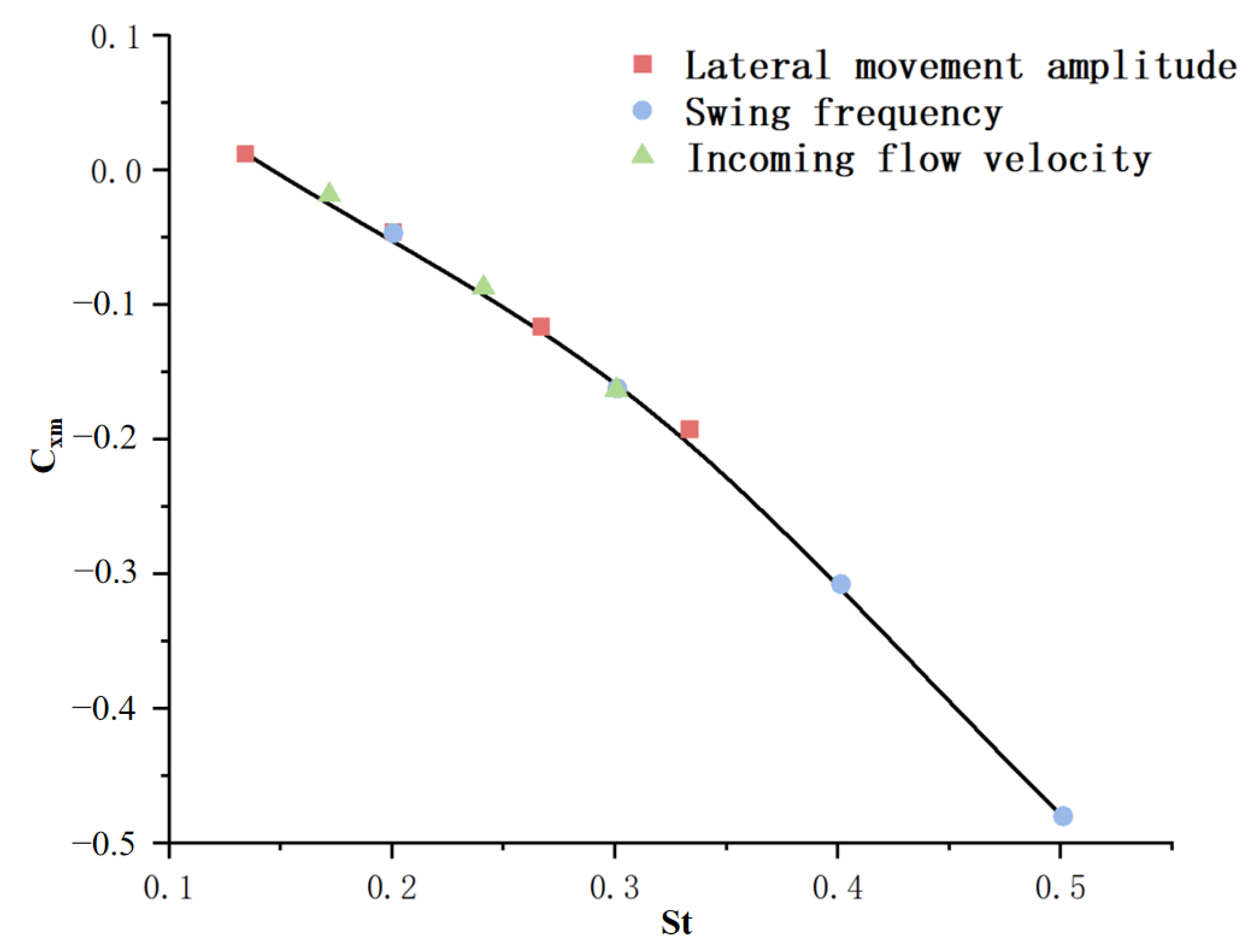
In light of the dynamic variation law of the vortex energy field with the tail swing parameters, Su Boyue et al. [102] systematically explored the regulatory effect of the Strouhal number (St) on the development of vortex energy by using a dynamic grid combined with the RNG k-ε turbulence model. As shown in Figure 18 and Table 5, in order to study the influence of the St number on the hydrodynamic coefficient, they achieved the change in the St number by regularly varying the flow velocity, swing frequency, and lateral movement amplitude. It was found that as the St increased, the mean hydrodynamic coefficient Cxm gradually decreased; that is, the average thrust coefficient Kt gradually increased. This achievement also further clarifies the quantitative correlation between the tailing frequency and the development of vortex energy.

4.2. Self-Driving Principle of Bionic Flexible TENG Sensors

Based on the characteristics of the vortex energy field induced by fish tail wagging movement [103,104,105,106], the development of self-driven sensors that can capture micro-energy from the vortex field and monitor the state of fish schools is an important research direction in this field. The bionic flexible TENG sensor is designed by imitating the structure and function of biological organs. It features high flexibility, high sensitivity, self-driving capabilities, and other advantages and is suitable for complex Marine environments.
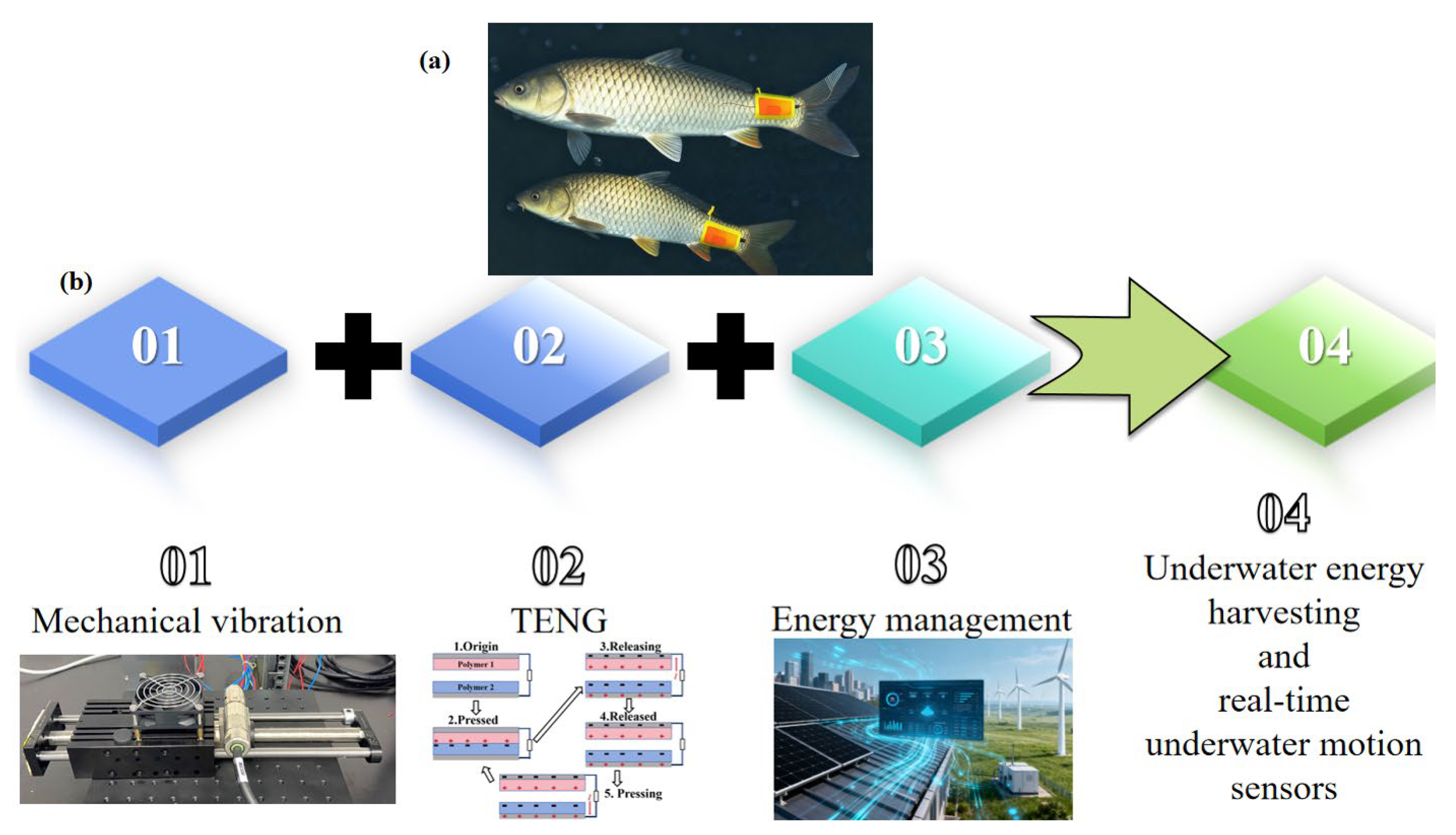
From the current research status of technical realization and application implementation, there are already many research achievements that have provided key support for the application of bionic flexible TENG sensors in deep-sea cage aquaculture scenarios. In terms of the integration of bionic structural design and underwater perception functions, the bionic self-driven triboelectric tactile sensor proposed by Peng Xu et al. [107] achieves high-precision perception of the underwater environment by simulating the structural characteristics of biological perception organs. The self-driven characteristics and high-sensitivity design of this sensor can be directly used for real-time capture of the swimming trajectories of fish in deep-sea cages. It provides an accurate perception tool for analyzing the distribution of vortex energy fields induced by fish tail wagging movement. In response to the strong corrosiveness and sealing protection requirements of deep-sea environments, Zhang Yanrong et al. [108] developed the sealed bionic fishtail structure TENG, which is more adaptable. This sensor takes the bionic fishtail as its core structure and combines anti-corrosion coating technology. While ensuring structural stability, it can efficiently capture mechanical energy during underwater movement (such as the vortex energy generated by fish tail wagging) and convert it into electrical energy. Its energy capture mechanism is highly consistent with the research direction of “vortex field micro-energy capture” focused on in this paper. It can be used as the core component of self-driven monitoring equipment in deep-sea cages to continuously monitor the activity status of fish and environmental parameters. From the perspective of a systematic review of technical application scenarios, Li Daoliang et al. [109] pointed out that TENG technology, with its self-driven and low-power consumption characteristics, has become one of the core technologies for the wearable monitoring of fish and in situ monitoring of aquaculture environments. This review further verifies the feasibility of bionic flexible TENG sensors in fishery scenarios, as shown in Figure 19. The “sensor-energy capture integration” design concept summarized in it also provides theoretical and application references for the development of the “vortex energy capture—fish population status monitoring” dual-function sensor studied in this paper. It is conducive to promoting the transformation of technology from laboratory research to practical application in deep-sea cage aquaculture.

4.3. Multi-Physical Field Coupling Micro-Energy Management System

During the interaction between fish schools and net cage flow fields, the micro-energy generated by the tail wagging movement of fish involves various physical fields such as flow fields, electric fields, and mechanical fields [110]. The coupling effect among these physical fields makes the process of energy conversion and transfer more complex. Therefore, the development of a multi-physics field coupled micro-energy management system is the key to achieving the effective collection, storage, and utilization of micro-energy.
The main objective of this chapter is to establish a multi-physics field coupled micro-energy management system to simulate the hydrodynamic characteristics and motion behavior of deep-sea cages and to provide a new numerical method for the design and optimization of deep-sea cages.
The specific research methods are as follows:
1.
CFD model establishment:
Utilize the CFD model to calculate the flow field around the cage. The governing equation of fluid flow is the Navier–Stokes equation, and the k-ε turbulence model is adopted to seal this equation. The cage is simplified as a porous medium, and the resistance of the cage to water flow is simulated through the porous medium model.
2.
DEM model establishment:
Utilize the DEM model to simulate the movement of the cage structure. The cage structure is discretized into a series of discrete units, and the contact force between the units is calculated through the Hertz–Mindlin contact model. The explicit central difference method is adopted to solve the motion equation of the element.
3.
Coupling of CFD and DEM models:
Coupling between CFD and DEM models is achieved through the exchange of force and displacement. The force exerted by the fluid on the cage structure is calculated by the CFD model and passed to the DEM model. The displacement of the cage structure calculated by the DEM model is then passed to the CFD model to update the position of the porous medium.
4.
Model verification:
By comparing the simulation results with the experimental data, the established CFD-DEM coupling model is verified. The experimental data are derived from the literature or self-designed experiments.
5.
Case study:
Conduct a case study on deep-sea cages using the validated CFD-DEM coupling model. Analyze the influence of different factors such as flow velocity, cage structure, and mooring system on the hydrodynamic characteristics and movement behavior of the cage.

4.3.1. CFD Model

The governing equations of fluid flow in the CFD model are the Navier–Stokes equations, which can be expressed in the tensor form as follows:
ρ t + ( ρ u i ) x i = 0
( ρ u i ) t + ( ρ u i u j ) x j = p x i + x j μ u i x j + u j x i + S i
where ρ is the fluid density, t is time, u i and u j are the velocity components in the x i and x j directions, respectively, p is the pressure, μ is the dynamic viscosity, and S i is the source term.
In this study, the k-ε turbulence model is used to close the Navier–Stokes equations. The transport equations of the turbulent kinetic energy k and the dissipation rate ε are as follows:
( ρ k ) t + ( ρ u i k ) x i = x j μ t σ k k x j + G k ρ ε
( ρ ε ) t + ( ρ u i ε ) x i = x j μ t σ ε ε x j + C 1 ε ε k G k C 2 ε ρ ε 2 k
where μ t is the turbulent viscosity, σ k and σ ε are the turbulent Prandtl numbers for k and ε, respectively, G k is the generation of turbulent kinetic energy due to mean velocity gradients, and C 1 ε and C 2 ε are model constants.
The deep-sea cage is simplified as a porous medium in the CFD model. The porous medium model is used to simulate the resistance of the cage to the water flow. The momentum equation of the porous medium is modified as follows:
( ρ u i ) t + ( ρ u i u j ) x j = p x i + x j μ u i x j + u j x i μ K u i C 2 ρ 2 | u | u i + S i
where K is the permeability of the porous medium, C 2 is the inertial resistance coefficient, and u = u 1 2 + u 2 2 + u 3 2 .
The permeability K and inertial resistance coefficient C 2 of porous media can be determined by experimental data or empirical formulas. This study employs the empirical formula used by E. C. Clukey et al. [111] to calculate the permeability and inertial resistance coefficient of deep-sea cages:
K = d 2 150 ε 3 ( 1 ε ) 2
C 2 = 3.5 d 1 ε ε 3
where d is the diameter of the cage wire, and ε is the porosity of the cage.

4.3.2. DEM Model

The cage structure is discretized into a series of discrete elements in the DEM model. In this study, the cage structure is composed of rigid rods and flexible nets. The rigid rods are discretized into beam elements, and the flexible nets are discretized into truss elements.
The beam element is used to simulate the rigid rod, and its motion equation can be expressed as follows:
M u ¨ + C u ˙ + K u = F
where M is the mass matrix, C is the damping matrix, K is the stiffness matrix, u is the displacement vector, u ˙ is the velocity vector, u ¨ is the acceleration vector, and F is the force vector.
The truss element is used to simulate the flexible net, and its motion equation is also expressed by Formula (26).
The contact force between elements is calculated by the Hertz–Mindlin contact model in the DEM model. The Hertz–Mindlin contact model considers the normal and tangential contact forces between elements and has been widely used in the simulation of granular materials.
The normal contact force between two elements can be calculated as follows:
F n = 4 3 E * R * δ n 3 2
where E * is the equivalent Young’s modulus, R * is the equivalent radius, and δ n is the normal overlap between the two elements.
The tangential contact force between two elements can be calculated as follows:
F t = G * R * δ t
where G * is the equivalent shear modulus, and δ t is the tangential displacement between the two elements.
The motion equations of the elements are solved by the explicit central difference method in the DEM model. The explicit central difference method is a simple and efficient numerical integration method, which has been widely used in the simulation of dynamic systems.
The acceleration, velocity, and displacement of the elements at time t + Δ t can be calculated as follows:
u ¨ t + Δ t = F t + Δ t 2 C u ˙ t + Δ t 2 K u t + Δ t 2 M u ˙ t + Δ t = u ˙ t + 1 2 u ¨ t + u ¨ t + Δ t Δ t u t + Δ t = u t + u ˙ t Δ t + 1 2 u ¨ t ( Δ t ) 2
where Δ t is the time step.

4.3.3. Coupling of CFD and DEM Models

Coupling between the CFD and DEM models is achieved through the exchange of forces and displacements. The force exerted by the fluid on the cage structure is calculated by the CFD model and transferred to the DEM model, and the displacement of the cage structure calculated by the DEM model is transferred to the CFD model to update the position of the porous medium.
The force exerted by the fluid on the cage structure can be calculated by integrating the pressure and shear stress on the surface of the cage structure:
F f = S ( p n + τ t ) d S
where F f is the force exerted by the fluid on the cage structure, S is the surface area of the cage structure, n is the unit normal vector of the surface, t is the unit tangent vector of the surface, p is the pressure, and τ is the shear stress.
The displacement of the cage structure calculated by the DEM model is transferred to the CFD model to update the position of the porous medium. The updated position of the porous medium is used to recalculate the permeability and inertial resistance coefficient of the porous medium, and then the flow field around the cage structure is recalculated by the CFD model.

4.4. Model Verification and Convergence Analysis

To ensure the accuracy and reliability of the CFD-DEM coupling model established in this paper, the grid sensitivity analysis and the verification of the convergence of time steps were carried out successively in this section, and the numerical simulation results were compared with the published experimental data.

4.4.1. Grid Sensitivity Analysis

To determine the optimal grid scheme, three groups of structured grids of different sizes were designed (as shown in Table 6). The core computing domain (cage area) was encrypted with grids, while the non-core domain (five times the diameter of the cage) adopted a gradient transition. The influence of the grid size on the results was evaluated by taking the total resistance of the net coating and the average flow velocity inside the net box as indicators.
The results show that when the grid size is reduced from 5 cm (thick grid) to 3 cm (medium grid), the calculated resistance value changes by 10.8% and the flow velocity changes by 11.5%. When further reduced to 1 cm (fine grid), the resistance change was only 4.7%, and the flow velocity change was 3.1%. According to the grid independence determination criterion (change rate ≤ 5%), the middle grid (3 cm of the cage area) is selected as the benchmark scheme, taking into account both calculation accuracy and efficiency.

4.4.2. Verification of Convergence of Time Steps

The selection of time steps is crucial for the stability of explicit algorithms. This paper establishes three different time steps: 0.01 s, 0.005 s (reference), and 0.001 s. The total kinetic energy of the system and the tension of the mooring line are taken as the convergence criteria. The results show that when the time step is reduced from 0.005 s to 0.001 s, the variation range of the key physical quantity is less than 1%. Therefore, choosing 0.005 s as the calculation time step can ensure the accuracy of the results while achieving efficient calculation.

4.4.3. Verification by Comparison with Experimental Data

To further verify the model, we compared the simulation results with the deformation experimental data of HDPE circular gravity cages under constant flow reported in Huang [79]. Under the same flow velocity (0.4 m/s) and cage structure parameters, the maximum horizontal displacement of the net garment calculated by the model in this paper is 2.85 m. Compared with the experimental value of 2.78 m in the literature, the relative error is 2.5%. The overall deformation contour of the net garment is also consistent with the height observed in the experiment.
The verification work of the above series has fully demonstrated that the CFD-DEM coupling model established in this paper has sufficient accuracy and reliability in predicting the hydrodynamic response and structural deformation of deep-water cages, laying a solid numerical foundation for subsequent case studies and analyses.

5. Conclusions

5.1. Limitations

5.1.1. Limitations in Multi-Field Coupling Dynamic Mechanism Research

The multi-field coupling dynamic model constructed in this study focuses on the “net jacket-fluid-structure coupling—multi-body system energy transfer—fish population flow field” three-level mechanism, but there are still deficiencies in the integration of spatiotemporal scales and the characterization of nonlinear factors. In terms of scale integration, the current model separately describes the microscale porous media seepage behavior of the net jacket (based on the Brinkman–Darcy equation) and the macroscale mooring system dynamics (based on Catenary Theory) but lacks a unified scale transition framework. This leads to inaccuracies in the simulation of energy transfer between microscale vortex shedding and macroscale structural vibration, especially when the net jacket undergoes large nonlinear deformation (such as local folding with curvature changes greater than 0.5 m−1).
In the characterization of nonlinear factors, the model considers the viscoelasticity of the net material (fractional-order Burgers model) and fluid–structure coupling nonlinearity but ignores the time-varying characteristics of biological factors. For example, the dynamic feedback of fish school density and swimming speed on the flow field is treated as a static boundary condition, failing to capture the real-time interaction between the “fish-induced vortex field” and the “net structure vibration field”. Experimental verification also has limitations: the wave–current combined action test system adopts regular waves and steady currents, which cannot fully replicate the randomness of extreme sea conditions (such as freak waves with a wave steepness exceeding 0.14) and the unsteadiness of upwelling currents, resulting in insufficient verification of the model’s reliability under extreme loads.

5.1.2. Deficiencies in Self-Powered Sensing System Development

The curved surface adaptive TENG array designed for the net jacket structure still faces bottlenecks in energy conversion efficiency and long-term reliability. In terms of energy conversion, the current design achieves a low-frequency energy conversion rate of approximately 15–20% under laboratory conditions, but in actual sea trials, the conversion efficiency drops by more than 40%. This is mainly due to the failure of the array to adapt to the multimodal vibration characteristics of the net jacket—under the combined action of wind, waves, and the current, the net jacket exhibits both low-frequency (0.1–1 Hz) overall swing and high-frequency (5–10 Hz) local vibration, while the current TENG unit only optimizes the contact–separation mode for low-frequency motion, resulting in inefficient utilization of high-frequency vibration energy [48]. The existing TENG arrays face three core limitations in Marine environments: Firstly, the NaCl solution leads to charge dissipation in the friction layer and electrode corrosion, resulting in an output decline of nearly 50% within three months [112]. Second, traditional packaging cannot withstand the water pressure above 1000 m and is prone to cracking and failure [113]. Thirdly, in a humid environment, the leakage current increases, and the output stability drops by more than 30%, making it difficult to meet the one-year maintenance-free requirement of deep-sea cages [114].
In terms of long-term reliability, although the PDMS/AgNWs composite film coated with PTFE has passed 500,000 cycles of durability testing in simulated seawater [109], the actual Marine environment contains suspended sediments (particle size 1–100 μm) and biofouling organisms (such as barnacles and algae) [53]. The abrasion of sediments on the friction layer and the adhesion of biofouling lead to a 30–50% decrease in the output voltage of the TENG array after 3 months of immersion, which is far from meeting the 1-year maintenance-free requirement of deep-sea aquaculture equipment. In addition, the energy management module of the sensing system lacks adaptive adjustment capabilities—when the vibration amplitude of the net jacket is less than 5 mm, the output power of the TENG is insufficient to drive the wireless transmission module, resulting in data loss.

5.1.3. Gaps in Fish–Cage Flow Field Interactions and Micro-Energy Capture

The research on the vortex energy field induced by fish tail swing mainly focuses on single fish or small-scale fish schools (≤50 individuals), and there is a lack of exploration of the “collective vortex effect” of large-scale fish schools (≥1000 individuals) in deep-sea cages. Experimental observations show that large-scale fish schools form a “rotational flow field” with a tangential velocity of 0.2–0.5 m/s inside the cage, which superimposes with the external wave–current flow field to generate complex turbulent structures. However, the current numerical simulation cannot accurately characterize the energy distribution of this superimposed flow field, leading to errors in the design of micro-energy capture points.
For the bionic flexible TENG sensor, its sensitivity to low-amplitude vortex signals (pressure fluctuation amplitude < 1 Pa) is insufficient. The sensor’s current detection limit is 2 Pa, which cannot capture the weak vortex disturbance generated by juvenile fish (body length < 10 cm) tail swing. In addition, the multi-physics field coupling micro-energy management system based on CFD-DEM coupling only realizes the one-way transmission of force and displacement between the flow field and the structure and does not consider the reverse influence of the TENG array’s energy capture behavior on the net jacket vibration—when the TENG unit captures energy, it generates additional damping (approximately 0.05 N·s/m), which may change the natural frequency of the net jacket and affect the structural stability assessment results.

5.2. Prospects

5.2.1. Optimization of Multi-Field Coupling Dynamic Model

In the future, researchers can build an integrated multi-scale coupling model of “micro-meso-macro” based on homogenization methods. At the microscopic scale, the lattice Boltzmann method is used to simulate the infiltration behavior of seawater in the mesh (pore diameter 2–5 cm) and the interaction between suspended particles and the mesh surface. At the mesoscale scale, the deformation and contact force transfer of the net nodes will be characterized by the discrete element method. At the macroscale, the finite volume method will be used to calculate the overall dynamic response of the cage mooring system. The three scales are coupled by the volume averaging method to achieve a seamless connection of energy transfer between different scales.
In terms of biological factor integration, a dynamic fish school model based on the Reynolds-Averaged Navier–Stokes (RANS) equation was established. The model will consider the collective behavior of fish schools (such as aggregation and dispersion) and the time-varying characteristics of tail swing frequency (1–5 Hz) and amplitude (2–10 cm) and couple it with the net sleeve flow field model to realize the real-time simulation of the “fish-structure-fluid” interaction. In addition, a simulation platform can be built to generate strange waves and irregular upwelling, and the model can be verified by measuring the net sheath deformation and mooring tension under extreme loads so as to improve the applicability of the model under complex sea conditions.

5.2.2. Upgrade of Self-Powered Sensing System

Researchers can develop a multimodal adaptive TENG array to achieve the efficient capture of low- and high-frequency vibrational energy. The array will have a “double-layer structure”: the bottom layer will use a serpentine electrode-based contact–separation mode TENG to capture low-frequency oscillation energy, and the top layer will integrate a piezoelectric–TENG composite unit to collect high-frequency local vibration energy. The two layers will share the same PDMS/AgNWs substrate, and the output energy will be integrated through a multi-port rectifier circuit; the overall energy conversion efficiency is expected to increase to more than 35%.
For long-term reliability, a “self-cleaning-antifouling” composite coating can be developed. Modified titanium dioxide nanoparticles were added to achieve photocatalytic self-cleaning under low-light conditions in deep-sea low-light conditions. At the same time, the surface will be modified with fluorosilane to reduce the adhesion of biofouling organisms, extending the service life of the TENG array to more than 18 months. In addition, an adaptive energy management module based on a boost converter with maximum power point tracking can be designed. When the vibration amplitude is less than 5 mm, the module stores the energy in the supercapacitor and triggers data transmission in batches; when the amplitude is greater than 5 mm, real-time data transmission will be realized to avoid data loss. Not only that, considering the limitations discussed above, the Marine adaptability of TENG needs to be further optimized in the future: First, develop an integrated friction layer material of “superhydrophobic—anti-corrosion”, such as PFOTS-modified PTFE/Al2O3 composite film, with the goal of extending the resistance to seawater corrosion life to more than two years; the second is to develop lightweight and high-voltage-resistant packaging, achieving no leakage for two years at a water depth of more than 1000 m; and thirdly, it integrates an intelligent humidity control module, which monitors the internal humidity in real time through micro-sensors and triggers the dehumidification function to ensure the stability of output throughout the entire life cycle.

5.2.3. Deepening of Fish–Cage Flow Field Interaction and Micro-Energy Capture Research

Researchers can expand the study of eddy energy fields in large schools of fish. A large circulating water tank was used to simulate the collective movement of fish, and the three-dimensional distribution of the eddy current energy field was captured by particle image velocimetry (PIV) technology with a spatial resolution of 0.1 mm and a temporal resolution of 1000 fps. A numerical model based on the large eddy simulation (LES) method was established to reveal the energy transfer mechanism between the collective vortex of fish schools and the vibration of the net sleeve and to determine the optimal layout of micro-energy capture points.
By imitating the lateral line structure of fish, a highly sensitive biomimetic flexible TENG sensor was developed. The sensor will use a hollow PDMS microchannel filled with ionic liquid as a sensitive unit to improve sensitivity by optimizing electrode spacing and ionic liquid concentration. The sensor will be integrated with the TENG array to realize the simultaneous monitoring of fish activity status and net structure status. In addition, a bidirectionally coupled CFD-DEM-TENG model can be established to consider the damping effect of energy capture on net sheath vibration, and the model can be used to optimize the structural parameters of the TENG element, such as mass and stiffness, to minimize the impact on the structural stability evaluation.

5.2.4. Broader Application Prospects

The theoretical system and technical achievements of this study can be extended to other deep-sea equipment, such as deep-sea observatories and underwater robots. The multi-field coupling dynamic model can provide a reference for the structural design of flexible components (such as observation platform mooring systems and robot manipulators) under complex Marine environments. The self-powered sensing system based on TENG can be adapted to the energy supply needs of underwater sensor networks in deep-sea observatories, reducing reliance on chemical batteries. In addition, the research on fish–cage flow field interactions can provide theoretical support for the design of eco-friendly deep-sea aquaculture systems, optimizing the flow field inside the cage to improve aquaculture efficiency and reduce environmental impacts.
In the long term, the integration of “structural health monitoring—aquaculture environment perception—energy self-supply” will be realized. By combining the multi-field coupling dynamic model, self-powered sensing system, and fish school behavior monitoring technology, an intelligent management platform for deep-sea aquaculture will be built. The platform can predict structural failures of cages 24–48 h in advance, adjust aquaculture density based on flow field changes, and achieve fully autonomous operation of deep-sea aquaculture, providing key technical support for the construction of the “Blue Granary” and the high-quality development of the Marine economy.

Author Contributions

Conceptualization, K.Y. (Kefan Yang) and D.Z.; methodology, K.Y. (Kefan Yang); software, S.Z.; validation, K.Y. (Keqi Yang) and Y.Z.; formal analysis, K.Y. (Kefan Yang); investigation, D.Z.; resources, D.Z.; data curation, K.Y. (Keqi Yang); writing—original draft preparation, K.Y. (Kefan Yang); writing—review and editing, D.Z.; visualization, D.Z.; supervision, D.Z.; project administration, D.Z.; funding acquisition, D.Z. All authors have read and agreed to the published version of the manuscript.

Funding

This study is supported by the Fund of Guangdong Provincial Key Laboratory of Intelligent Equipment for South China Sea Marine Ranching (Grant No. 2023B1212030003).

Data Availability Statement

Data is contained within the article.

Conflicts of Interest

The authors declare no conflict of interest.

References

  1. Yan, G.; Ni, X.; Mo, J. Research status and development trend of profound Marine aquaculture equipment technology. J. Dalian Ocean. Univ. 2018, 33, 123–129. (In Chinese) [Google Scholar] [CrossRef]
  2. Chen, Y.; Fang, R.; Qiao, J. China’s Marine aquaculture development research. J. Agric. Econ. 2012, 72–77+112. (In Chinese) [Google Scholar] [CrossRef]
  3. Zhu, Y.; Ju, X.; Chen, Y. Current Situation, Problems and Countermeasures of Deep-sea Cage Aquaculture in China. China Fish. Econ. 2017, 35, 72–78. (In Chinese) [Google Scholar]
  4. Hou, H.; Ju, X.; Chen, Y. The development trends of Deep-sea cage aquaculture abroad and its implications for China. World Agric. 2017, 162–166. (In Chinese) [Google Scholar] [CrossRef]
  5. Song, R.; Zhou, M.; Li, Y.; Zhang, H.; Lin, Z. Research Progress on Key Technologies of Deep-sea Cage Aquaculture Equipment. Mech. Eng. 2015, 134–138. (In Chinese) [Google Scholar]
  6. Hou, Y.; Li, Y.; Li, G.; Tong, X.; Wang, Y. Oil-spill detection sensor using ultraviolet-induced fluorescence for routine surveillance in coastal environments. Appl. Phys. B 2022, 128, 41. [Google Scholar] [CrossRef]
  7. Gonzaga, B.A.; Alves, D.L.; Albuquerque, M.D.G.; Espinoza, J.M.D.A.; Almeida, L.P.; Weschenfelder, J. Development of a Low-cost Ultrasonic Sensor for Groundwater Monitoring in Coastal Environments: Validation using Field and Laboratory Observations. J. Coast. Res. 2020, 95 (Suppl. 1), 1001–1005. [Google Scholar] [CrossRef]
  8. Xie, Y. Based on the Internet of Things of Marine Water Quality Wise Observation Solution Research. Master’s Thesis, Shanghai Ocean University, Shanghai, China, 2020. (In Chinese). [Google Scholar]
  9. Diaz, K.; Teh, Y. Design and Power Management of a Secured Wireless Sensor System for Salton Sea Environmental Monitoring. Electronics 2020, 9, 544. [Google Scholar] [CrossRef]
  10. Zhang, Y. Review on the Development of Marine Environment Monitoring Equipment Technology. Digit. Ocean. Underw. Attack Def. 2018, 1, 7–14. (In Chinese) [Google Scholar]
  11. Rodrigues, C.; Nunes, D.; Clemente, D.; Mathias, N.; Correia, J.M.; Rosa-Santos, P.; Taveira-Pinto, F.; Morais, T.; Pereira, A.; Ventura, J. Emerging triboelectric nanogenerators for ocean wave energy harvesting: State of the art and future perspectives. Energy Environ. Sci. 2020, 13, 2657–2683. [Google Scholar] [CrossRef]
  12. Liu, L.; Hu, T.; Zhao, X.; Lee, C. Recent progress in blue energy harvesting based on triboelectric nanogenerators. Nanoenergy Adv. 2024, 4, 156–173. [Google Scholar] [CrossRef]
  13. Jiang, Y.; Liang, X.; Jiang, T.; Wang, Z.L. Advances in triboelectric nanogenerators for blue energy harvesting and marine environmental monitoring. Engineering 2024, 33, 204–224. [Google Scholar] [CrossRef]
  14. Isabel, G.; Rodrigues, C.; Ventura, J. Sea state adaptation enhances power output of triboelectric nanogenerators for tailored ocean wave energy harvesting. Adv. Energy Mater. 2024, 14, 2302627. [Google Scholar]
  15. Li, X.; Xu, L.; Wang, Z.L. Networking strategies of triboelectric nanogenerators for harvesting ocean blue energy. Nanoenergy Adv. 2024, 4, 70–96. [Google Scholar] [CrossRef]
  16. Tan, D.; Chi, S.; Ou, X.; Zhou, J.; Wang, K. Some Advances in nonlinear frictional nanopower generation Energy capture technology. Acta Mech. Sin. 2024, 56, 2495–2510. (In Chinese) [Google Scholar]
  17. Gao, J.; Zhao, B.; Yang, C.; Rui, H.Y.; Gang, X.H. Development Trends and Prospects of Offshore Energy Storage Technology. Adv. New Renew. Energy 2020, 8. (In Chinese) [Google Scholar]
  18. Wang, Y. Research on Friction Nano-Electromagnetic Composite Flow Energy Capture and Energy Supply for Observation Nodes. Ph.D. Thesis, Dalian Maritime University, Dalian, China, 2023. (In Chinese). [Google Scholar]
  19. Dong, J. Research on Self-Powering Technology of Marine Buoys Based on Stackable Triboelectric Nanogenerators. Ph.D. Thesis, Dalian Maritime University, Dalian, China, 2021. (In Chinese). [Google Scholar]
  20. Lin, Z.W. Triboelectric nanogenerators as new energy technology for self-powered systems and as active mechanical and chemical sensors. ACS Nano 2013, 7, 9533–9557. [Google Scholar] [CrossRef]
  21. Li, P.; Tian, Y.; Qin, H.; Wei, B.; Deng, Z. Analysis of Flow Field Characteristics and Deformation of Nylon Mesh Based on Fluid-Structure Coupling. China Offshore Platf. 2023, 38, 48–56. (In Chinese) [Google Scholar]
  22. Ma, J. Energy Transfer Analysis of Multi-Body Systems. Ph.D. Thesis, Dalian University of Technology, Dalian, China, 2008. (In Chinese). [Google Scholar]
  23. Zhang, C. Fish Flow Field Interference Mechanism Research. Ph.D. Thesis, Nanjing University of Aeronautics and Astronautics, Nanjing, China, 2022. (In Chinese). [Google Scholar]
  24. Lin, X. Research on the Hydrodynamic Mechanism of Fish and Bird Migration. Ph.D. Thesis, Nanchang Hangkong University, Nanchang, China, 2017. (In Chinese). [Google Scholar]
  25. Tang, M. Flow Wave Net Structure Hydrodynamic Characteristics Research. Ph.D. Thesis, Dalian University of Technology, Dalian, China, 2020. (In Chinese). [Google Scholar]
  26. Zhang, K.; Liu, B.; Chen, H.; Chen, J.; Yao, H.D. Solving fluid-structure interaction of flexible net structures in current and waves based on a coupled truss–porous medium model. Ocean. Eng. 2025, 329, 121115. [Google Scholar] [CrossRef]
  27. Schäfer, F.; Kniesburges, S.; Uffinger, T.; Becker, S.; Grabinger, J.; Link, G.; Kaltenbacher, M. Numerical simulation of fluid-structure-and fluid-structure-acoustic interaction based on a partitioned coupling scheme. In High Performance Computing in Science and Engineering, Garching/Munich 2007: Transactions of the Third Joint HLRB and KONWIHR Status and Result Workshop, Leibniz Supercomputing Centre, Garching/Munich, Germany 3–4 December 2007; Springer: Berlin/Heidelberg, Germany, 2009. [Google Scholar]
  28. Wang, M.; Li, G.; Xia, C.; Jing, X.; Wang, R.; Liu, Q.; Cai, X. Facile preparation of cyclodextrin polymer materials with rigid spherical structure and flexible network for sorption of organic contaminants in water. Chem. Eng. J. 2021, 411, 128489. [Google Scholar] [CrossRef]
  29. Rosén, T.; Mittal, N.; Roth, S.V.; Zhang, P.; Lundell, F.; Söderberg, L.D. Flow fields control nanostructural organization in semiflexible networks. Soft Matter 2020, 16, 5439–5449. [Google Scholar] [CrossRef]
  30. Hu, Z. Numerical Simulation Research on the Structural Safety of Net Jackets in Large Deep-Sea and Far-Sea Cages. Ph.D. Thesis, Shandong University, Jinan, China, 2024. (In Chinese). [Google Scholar]
  31. Hu, B.; Yang, X. Current Situation and Development Trend of Deep-sea Aquaculture Cages at Home and Abroad. Silicon Val. 2008, 28–29. (In Chinese) [Google Scholar]
  32. Pan, Y.; Zhang, J.; Li, L.; Liu, C.; Sun, Z.; Hong, J. Numerical simulation of hydrodynamic characteristics of ultra-large diameter aquaculture cages under waves action. Ocean. Eng. 2025, 338, 121981. [Google Scholar] [CrossRef]
  33. Zhang, D.; Zhao, B.; Jiang, H. Wave energy converter with floating-point absorber and catenary mooring: Dynamic coupling analysis. Front. Mar. Sci. 2024, 11, 1338330. [Google Scholar] [CrossRef]
  34. Ma, Y.; Si, K.; Xie, Y.; Liang, Z.; Wu, J.; Zhang, D.; Zhang, Y.; Cai, R. Global Marine Ranching Research: Progress and Trends through Bibliometric Analysis. Eng. Solut. Mech. Mar. Struct. Infrastruct. 2024, 1, 1–23. [Google Scholar] [CrossRef]
  35. Zhang, D.; Zhao, B.; Zhang, Y.; Zhu, K.; Yan, J. Study on Dynamic Characteristics and Fracture Failure of Rigid Truss Trawl System During Towing Process. J. Mar. Sci. Eng. 2025, 13, 586. [Google Scholar] [CrossRef]
  36. Gui, F.; Zhu, H.; Feng, D. Research Progress on Hydrodynamic Characteristics of Marine Aquaculture Netting. Fish. Mod. 2019, 46, 9–14. (In Chinese) [Google Scholar]
  37. Li, N.; Li, X.; Shi, W.; Liu, C. Numerical Simulation of Hydrodynamic Characteristics of Planar Mesh under Wave-Current Action. J. Shanghai Ocean. Univ. 2024, 33, 509–520. (In Chinese) [Google Scholar]
  38. Wu, H.; Liu, Q.; Fan, W. Research on Hydrodynamic Loads of Cage Nets and Net Jackets in Aquaculture. Mod. Fish. 2023, 50, 43–51. (In Chinese) [Google Scholar]
  39. Zhang, Y.M.; Bi, C.W.; Feng, L.; Huang, L.Y. Hydrodynamic response analysis of the aquaculture net under the combined action of irregular waves and currents. Ships Offshore Struct. 2024, 1–17. [Google Scholar] [CrossRef]
  40. Ling, A.; Liang, Y.; Zhao, D.; Fan, Z.; Zhao, Y. Marine aquaculture hydrodynamic characteristics is reviewed. The flexible net structure. Fish. Sci. Prog. 2024, 45, 223–236. (In Chinese) [Google Scholar] [CrossRef]
  41. He, W.; Liu, W.; Fu, S.; Wu, H.; Shan, C.; Wang, Z.; Xi, Y.; Wang, X.; Guo, H.; Liu, H.; et al. Ultrahigh Performance Triboelectric Nanogenerator Enabled by Charge Transmission in Interfacial Lubrication and Potential Decentralization Design. Research 2022, 2022, 9812865. [Google Scholar] [CrossRef]
  42. Zhang, C.; He, L.; Zhou, L.; Yang, O.; Yuan, W.; Wei, X.; Liu, Y.; Lu, L.; Wang, J.; Wang, Z.L. Active resonance triboelectric nanogenerator for harvesting omnidirectional water-wave energy. Joule 2021, 5, 1613–1623. [Google Scholar] [CrossRef]
  43. Li, X.; Zhang, D.; Zhang, D.; Li, Z.; Wu, H.; Zhou, Y.; Wang, B.; Guo, H.; Peng, Y. Solid-liquid triboelectric nanogenerator based on vortex-induced resonance. Nanomaterials 2023, 13, 1036. [Google Scholar] [CrossRef]
  44. Zhang, Q.; Li, L.; Wang, T.; Jiang, Y.; Tian, Y.; Jin, T.; Yue, T.; Lee, C. Self-sustainable flow-velocity detection via electromagnetic/triboelectric hybrid generator aiming at IoT-based environment monitoring. Nano Energy 2021, 90, 106501. [Google Scholar] [CrossRef]
  45. Wang, S.; Zhang, X.; Ma, T.; Kong, Y.; Gao, S.; Han, Q. Symmetrical Triboelectric In Situ Self-Powered Sensing and Fault Diagnosis for Double-Row Tapered Roller Bearings in Wind Turbines: An Integrated and Real-Time Approach. Adv. Sci. 2025, 12, 2500981. [Google Scholar] [CrossRef] [PubMed]
  46. Xu, L.; Wu, J.; Zhang, K.; Lu, J.; Li, J.; Hazarika, D.; Jin, H.; Luo, J. An instantaneous self-powered wireless sensing system based on a triboelectric nanogenerator and the human body. Nanoscale 2024, 16, 19355–19363. [Google Scholar] [CrossRef] [PubMed]
  47. Wang, W.; Yan, J.; Wang, X.; Pang, H.; Sun, C.; Sun, Y.; Wang, L.; Zhang, D. Research on the Performance of a Liquid–Solid Triboelectric Nanogenerator Prototype Based on Multiphase Liquid. Micromachines 2025, 16, 78. [Google Scholar] [CrossRef]
  48. Yang, K.F.; Xie, Y.; Si, K.; Yang, K.Q.; Zeng, S.; Zhang, D. Research Progress on Friction Nanogenerator Technology for Wave Energy Harvesting. Eng. Solut. Mech. Mar. Struct. Infrastruct. 2024. [Google Scholar] [CrossRef]
  49. Yan, J.; Sheng, Y.; Zhang, D.; Tang, Z. Research Progress in Fluid Energy Collection Based on Friction Nanogenerators. Micromachines 2023, 15, 40. [Google Scholar] [CrossRef]
  50. Chen, P.; Zhu, X.; Tian, G.; Feng, X. Recent advances of TENGs for marine applications: Opportunities and challenges coexist. Nano Energy 2025, 142, 111212. [Google Scholar] [CrossRef]
  51. Li, M.; Jin, S.; Meng, A.; Song, J.; Xu, Z.; Chen, Y.; Zeng, Y. A performance study on the drum-type energy harvesting device based on triboelectric nanogenerator. J. Electrost. 2025, 135, 104066. [Google Scholar] [CrossRef]
  52. Ji, C. Research on Flexible Acoustic Sensor Based on PDMS-AgNWs. Ph.D. Thesis, Taiyuan University of Technology, Taiyuan, China, 2019. (In Chinese). [Google Scholar]
  53. Deng, X.; Li, D.; Yang, J.; Wang, J. Research on Friction and Wear Properties of High-Performance High-Temperature Resistant Polymer Composites. Bull. Polym. Sci. 2008, 41–46. (In Chinese) [Google Scholar]
  54. Chen, X.; Chen, J.; Huang, L.; Nie, S.; Xu, W.; Yin, Y.; Zhang, S.; Pei, F.; Yu, K.; Su, W.; et al. Highly conductive omnidirectionally stretchable 2D transparent copper mesh electrodes and applications in optoelectronic devices. Adv. Mater. Technol. 2023, 8, 2201406. [Google Scholar] [CrossRef]
  55. Sun, P.; Wang, L.; Wang, L. Deepwater semi-submersible platform anchoring auxiliary power positioning system power consumption research. Ocean. Eng. 2010, 28, 24–30. (In Chinese) [Google Scholar] [CrossRef]
  56. Wen, X.; Gjerde, A.; Ong, M.C. Numerical investigation of pre-tension effects in mooring systems on global responses of gravity-type fish farms. Ocean. Eng. 2025, 337, 121832. [Google Scholar] [CrossRef]
  57. Wang, B.; Wang, H.; Liu, Z.; Cao, Z.; Yang, D.; Wang, F. Research Progress on Structural Design and Performance Analysis of Mooring System for Aquaculture Cages. J. Shanghai Ocean. Univ. 2025, 34, 176–187. (In Chinese) [Google Scholar]
  58. Liu, F.; Jiang, Z.; Cheng, T.; Xu, Y.; Zhu, H.; Wang, G.; Sun, G.; Zhang, Y. Study on the Dynamic Response of Mooring System of Multiple Fish Cages under the Combined Effects of Waves and Currents. J. Mar. Sci. Eng. 2024, 12, 1648. [Google Scholar] [CrossRef]
  59. Wang, H.; Gu, S.; Ma, G.; Huang, W.; Sun, Y.; Du, Z. Dynamic performance analysis of grid mooring system for gravity cages. Ships Offshore Struct. 2025, 20, 1143–1160. [Google Scholar] [CrossRef]
  60. Abdellah Mohammed, Y.; Sadek, M.G.; Alharthi, H.; Abdel-Jaber, G.T.; Backar, A.H. Characteristic properties of date-palm fibre/sheep wool reinforced polyester composites. J. Bioresour. Bioprod. 2023, 8, 430–443. [Google Scholar] [CrossRef]
  61. Michel, F.; Davies, P. Characterization of polyester mooring lines. In Proceedings of the International Conference on Offshore Mechanics and Arctic Engineering, Estoril, Portugal, 15–20 June 2008; Volume 48180. [Google Scholar]
  62. Liu, X.; Li, Z.; Zhu, D.; Gong, Q. Dynamic viscoelastic properties of polyethylene terephthalate. Plastics 2024, 53, 137–142. (In Chinese) [Google Scholar]
  63. da Silva, L.S.; Cazzolato, B.S.; Sergiienko, N.Y.; Ding, B.; Morishita, H.M.; Pesce, C.P. Statistical linearization of the Morison’s equation applied to wave energy converters. J. Ocean. Eng. Mar. Energy 2020, 6, 157–169. [Google Scholar] [CrossRef]
  64. Beji, S. Formulation of wave and current forces acting on a body and resistance of ships. Ocean. Eng. 2020, 218, 108121. [Google Scholar] [CrossRef]
  65. Liu, G.; Wang, Q.; Tian, X.; Xie, Y. The ocean structure small scale research and progress on hydrodynamic coefficients of pile. Chin. J. Ocean. Univ. (Nat. Sci. Ed.) 2020, 50, 136–144. (In Chinese) [Google Scholar] [CrossRef]
  66. Wang, F.; Zhang, J.; Zhu, Y.; Geng, Z.; Wang, F. Research and Progress on Hydrodynamics of Boat-type Aquaculture cages. Ships 2025, 36, 27. (In Chinese) [Google Scholar]
  67. Wang, G.; Tao, L.; Rong, B.; Rui, X. Research Progress of Dynamic Simulation Methods for Multi-field Coupled Systems. Adv. Mech. 2023, 53, 468–495. (In Chinese) [Google Scholar]
  68. Lin, M.; Wu, Q.; Tian, H.; Huang, L.; Huang, G.; Liu, B.; Wang, X.; Wang, G. Tension of mooring ropes and safety of jacket Foundation structure in the integrated system of offshore wind turbines and aquaculture cages. Acta Fish. Sin. 2024, 48, 107–119. (In Chinese) [Google Scholar]
  69. Kuan, J.; Čanić, S.; Muha, B. Fluid-poroviscoelastic structure interaction problem with nonlinear geometric coupling. J. Math. Pures Appl. 2024, 188, 345–445. [Google Scholar] [CrossRef]
  70. Bungartz, H.J.; Lindner, F.; Mehl, M.; Uekermann, B. A plug-and-play coupling approach for parallel multi-field simulations. Comput. Mech. 2015, 55, 1119–1129. [Google Scholar] [CrossRef]
  71. Gong, S.; Gao, J.; Yan, M.; Song, Z.; Shi, H. Effects of floater motion on wave loads during steady-state gap resonance occurring between two non-identical boxes. Ocean. Eng. 2025, 323, 120649. [Google Scholar] [CrossRef]
  72. Zeng, X.; Shi, W.; Feng, X.; Shao, Y.; Li, X. Investigation of higher-harmonic wave loads and low-frequency resonance response of floating offshore wind turbine under extreme wave groups. Mar. Struct. 2023, 89, 103401. [Google Scholar] [CrossRef]
  73. Ling, H.; Yang, P.; Zhang, Z.; Wang, Z. Complex wave loads and hydroelastic responses of a very large tourism floating platform ‘Ocean Diamond’. Ocean. Eng. 2022, 265, 112608. [Google Scholar] [CrossRef]
  74. Wang, Z.; Huang, D.; He, H.; Yang, F.; Li, W.; Chen, Y. Dynamic Response and Fatigue Analysis of a New Marine Gravitational Energy Storage System Under Wave Loads. J. Mar. Sci. Eng. 2024, 12, 2196. [Google Scholar] [CrossRef]
  75. Fan, Y.; Zhao, Z.; Yu, J.; Wu, L. Net hydrodynamic load impact factor analysis. Mar. Eng. 2025, 47, 1–6+77. (In Chinese) [Google Scholar] [CrossRef]
  76. Mi, S.; Wang, M.; Avital, E.J.; Williams, J.J.; Chatjigeorgiou, I.K. An implicit Eulerian–Lagrangian model for flow-net interaction using immersed boundary method in OpenFOAM. Ocean. Eng. 2022, 264, 112843. [Google Scholar] [CrossRef]
  77. Cao, H.; Wan, D. Research on the Development and Application of Numerical Wave Water Pool Based on OpenFOAM. In Strive to Be Strong and Realize the Dream of the Maritime Frontier—Proceedings of the 8th Plenary Session of the Ship Mechanics Academic Committee of the China Shipbuilding Society; State Key Laboratory of Marine Engineering, School of Naval Architecture, Ocean and Civil Engineering, Shanghai Jiao Tong University: Shanghai, China, 2014; pp. 319–332. (In Chinese) [Google Scholar]
  78. Chen, C.; Wang, W.; Zheng, J.; Zheng, Y.; Shi, X.; Liu, C. Water flow under the action of the flat metal net water resistance characteristic numerical simulation. J. Dalian Ocean. Univ. 2017, 32, 363–368. (In Chinese) [Google Scholar] [CrossRef]
  79. Huang, X.; Guo, G.; Tao, Q.; Hu, Y. Numerical Simulation of Deformation Characteristics under Force of HDPE Circular Gravity Cage. South. Fish. Sci. 2013, 9, 126–131. (In Chinese) [Google Scholar]
  80. Chen, Y.; Pang, G.; Huang, X.; Li, G.; Yuan, T.; Hu, Y.; Tao, Q. The influence of net coating on the structural response of self-elevating truss cages. South. Fish. Sci. 2024, 20, 43–53. (In Chinese) [Google Scholar]
  81. Scherz, L.; Kriegesmann, B.; Pedersen, C.B. A condition number-based numerical stabilization method for geometrically nonlinear topology optimization. Int. J. Numer. Methods Eng. 2024, 125, e7574. [Google Scholar] [CrossRef]
  82. Ceglie, M.; Violano, G.; Afferrante, L.; Menga, N. Hysteresis in Approach-Retraction Frictional Contacts with Geometric and Material Nonlinearity. Mater. Sci. Forum 2025, 1151, 109–115. [Google Scholar] [CrossRef]
  83. Dai, H. Research on Fluid-Structure Coupled Nonlinear Vibration Mechanism and Its Driving Utilization. In Abstracts of the 19th National Conference on Nonlinear Vibration and the 16th National Conference on Nonlinear Dynamics and Motion Stability; Department of Engineering Mechanics, School of Aeronautics and Astronautics, Huazhong University of Science and Technology: Wuhan, China, 2023; Volume 4, (In Chinese). [Google Scholar] [CrossRef]
  84. Pan, Y. Research on Ocean Energy Harvesting and Sensing Technology Based on Nanopower Generation. Master’s Thesis, Beijing University of Technology, Beijing, China, 2024. (In Chinese). [Google Scholar]
  85. Liang, N.; Miao, C.; Cui, H.; Wang, J.; Yang, X. Simulation Study on Coupling System of Raft Wave Energy Conversion and Triboelectric Nanogenerator Energy Output. Adv. New Renew. Energy 2022, 10, 265–270. (In Chinese) [Google Scholar] [CrossRef]
  86. Pan, C.Y.; Dai, Z.H.; Ma, H.X.; Zheng, J.R.; Leng, J.; Xie, C.; Yuan, Y.P.; Yang, W.C.; Yaliun, Y.X.; Song, X.M.; et al. Self-powered and speed-adjustable sensor for abyssal ocean current measurements based on triboelectric nanogenerators. Nat. Commun. 2024, 15, 6133. (In Chinese) [Google Scholar] [CrossRef] [PubMed]
  87. Zhao, Y.; Zhang, J.; Liu, Y.; Sun, K.; Zhang, C.; Wu, W.; Teng, F. Numerical assessment of the environmental impacts of deep sea cage culture in the Yellow Sea, China. Sci. Total Environ. 2020, 706, 135752. [Google Scholar] [CrossRef] [PubMed]
  88. Zhang, C.; Hao, Y.; Yang, J.; Su, W.; Zhang, H.; Wang, J.; Wang, Z.; Li, X. Recent advances in triboelectric nanogenerators for marine exploitation. Adv. Energy Mater. 2023, 13, 2300387. [Google Scholar] [CrossRef]
  89. Yu, J.; Guo, Y.; Yang, L. Solid-liquid Triboelectric Nanogenerator. J. Mech. Eng. 2021, 57, 160–181. (In Chinese) [Google Scholar]
  90. Zhu, H.; Liang, J.; Wang, S.; Huang, J.; Chen, Z. A multimodal PDMS triboelectric nanogenerator sensor based on anodised aluminium oxide template preparation for object recognition. J. Mater. Chem. A 2023, 11, 24158–24168. [Google Scholar] [CrossRef]
  91. Zhou, S.; Zhang, Y.; Li, X.; Xu, C.; Halim, J.; Cao, S.; Rosen, J.; Strömme, M. A mechanically robust spiral fiber with ionic–electronic coupling for multimodal energy harvesting. Mater. Horiz. 2024, 11, 3643–3650. [Google Scholar] [CrossRef]
  92. Jin, S.Y. Based on Drum TENG Device of Energy Collection and Vibration Testing Research. Master’s Thesis, Hangzhou University of Electronic Science and Technology, Hangzhou, China, 2024. (In Chinese). [Google Scholar]
  93. Yang, H. Structural Design and Performance Research of a Triboelectric Nanogenerator for Water Wave Energy Harvesting. Master’s Thesis, Zhejiang Normal University, Jinhua, China, 2024. (In Chinese). [Google Scholar]
  94. Park, S.G.; Zhou, J.; Dong, S.; Li, Q.; Yoshida, T.; Kitazawa, D. Characteristics of the flow field inside and around a square fish cage considering the circular swimming pattern of a farmed fish school: Laboratory experiments and field observations. Ocean. Eng. 2022, 261, 112097. [Google Scholar] [CrossRef]
  95. Gansel, L.C.; Rackebrandt, S.; Oppedal, F.; McClimans, T.A. Flow fields inside stocked fish cages and the near environment. J. Offshore Mech. Arct. Eng. 2014, 136, 031201. [Google Scholar] [CrossRef]
  96. Dong, S.; Park, S.G.; Zhou, J.; Li, Q.; Yoshida, T.; Kitazawa, D. Flow Field Inside and Around a Square Fish Cage Considering Fish School Swimming Pattern. In Proceedings of the International Conference on Offshore Mechanics and Arctic Engineering, Virtual, 21–30 June 2021; Volume 85154. [Google Scholar]
  97. Tang, M.F.; Xu, T.J.; Dong, G.H.; Zhao, Y.P.; Guo, W.J. Numerical simulation of the effects of fish behavior on flow dynamics around net cage. Appl. Ocean. Res. 2017, 64, 258–280. [Google Scholar] [CrossRef]
  98. Borazjani, I.; Mohsen, D. The fish tail motion forms an attached leading edge vortex. Proc. R. Soc. B Biol. Sci. 2013, 280, 20122071. [Google Scholar] [CrossRef]
  99. Guo, C.; Liang, Z.; Han, Y.; Kui, Y.; Xu, P.; Sun, L. Experimental Study on Linear Accelerated Swimming of Zebrafish. Acta Mech. Sin. 2022, 54, 2446–2459. (In Chinese) [Google Scholar]
  100. Yang, G.; Hu, X.; Zhang, B.; Long, Z.; Zhang, Y.; Shi, X. Analysis of Dynamic Characteristics of Free-Swimming Grass Carp Based on Particle Image Velocimetry (PIV). J. Dalian Ocean. Univ. 2021, 4, 833–841. (In Chinese) [Google Scholar] [CrossRef]
  101. Hu, W. Numerical and analytical study on a tail-flaping model for fish fast C-start. Acta Mech. Sin. 2004, 20, 16–23. (In Chinese) [Google Scholar] [PubMed]
  102. Su, B.; Zhai, S.; Bai, Y.; Zhang, J. Analysis of hydrodynamic and vortex Structure Characteristics of Tail Fin Swing Propulsion. J. Ship Mech. 2024, 28, 220–228. (In Chinese) [Google Scholar]
  103. Cui, Z.; Jiang, H.; He, J.; Tong, Z. Research Progress and Key Technology Analysis of Swimming Mechanism of BCF bionic fish. J. Mech. Eng. 2015, 51, 177–184. (In Chinese) [Google Scholar] [CrossRef]
  104. Tong, B. The Propulsion Mechanism of Fish ‘Wavy Swimming’. Mech. Chin. Pract. 2000, 22. (In Chinese) [Google Scholar]
  105. Chu, W.; Yuan, Q.; Kong, X.; Zhang, Z.; Li, H.; Qian, W. Analysis of Tail fin Propulsion Mechanism and Influencing Parameters of Swimming Ability of Fish. J. Shanghai Ocean. Univ. 2022, 31, 1224–1234. (In Chinese) [Google Scholar]
  106. Sun, W.; Liu, S.; Wu, G.; Zhou, Y.; Ren, X. Research Progress on the Swimming mechanism of fish. J. Dalian Ocean. Univ. 2024, 39, 698–707. (In Chinese) [Google Scholar]
  107. Xu, P.; Liu, J.; Liu, X.; Wang, X.; Zheng, j.; Wang, S.; Chen, T.; Wang, H.; Wang, C.; Fu, X.; et al. A bio-inspired and self-powered triboelectric tactile sensor for underwater vehicle perception. Npj Flex. Electron. 2022, 6, 25. [Google Scholar] [CrossRef]
  108. Zhang, Y.; Xia, C.; Zhong, L.W. The sealed bionic fishtail-structured TENG based on anticorrosive paint for ocean sensor systems. Nano Energy 2023, 108, 108210. [Google Scholar] [CrossRef]
  109. Li, D.; Wang, S.; Wang, C. Application Progress of Flexible Wearable Sensing Technology in Smart Fishery. Trans. Chin. Soc. Agric. Eng. 2023, 39, 1–13. (In Chinese) [Google Scholar]
  110. Zhang, B.; Hu, X.; Yang, G.; Long, Z.; Huang, H.; Shi, X. Study on the Dynamics of Juvenile Grass Carp Cruising Based on Pressure Field. J. Hydroelectr. Power 2021, 40, 79–88. (In Chinese) [Google Scholar]
  111. Clukey, E.C.; Silva, A.J. Permeability of deep-sea clays: Northwestern Atlantic. Mar. Georesources Geotechnol. 1982, 5, 1–26. [Google Scholar] [CrossRef]
  112. Du, J.; Hu, L.; Sun, J.; Song, Q.; Chen, M.; Xiao, J. Tribo-corrosion Performance of 7075-T6 Al-alloy in 3.5%NaCl Solution. J. Chin. Soc. Corros. Prot. 2025, 45, 803–811. [Google Scholar] [CrossRef]
  113. Chen, Z.; Mei, Y.; Liu, S.; Li, H.; Liu, L.; Lei, X.; Zhou, Y.; Gao, X. Electronic Packaging reliability: Past, Present and future. J. Mech. Eng. 2021, 57, 248–268. (In Chinese) [Google Scholar]
  114. Sun, Y.; Zheng, Y.; Wang, R.; Lei, T.; Liu, J.; Fan, J.; Shou, W.; Liu, Y. 3D micro-nanostructure based waterproof triboelectric nanogenerator as an outdoor adventure power source. Nano Energy 2022, 100, 107506. [Google Scholar] [CrossRef]
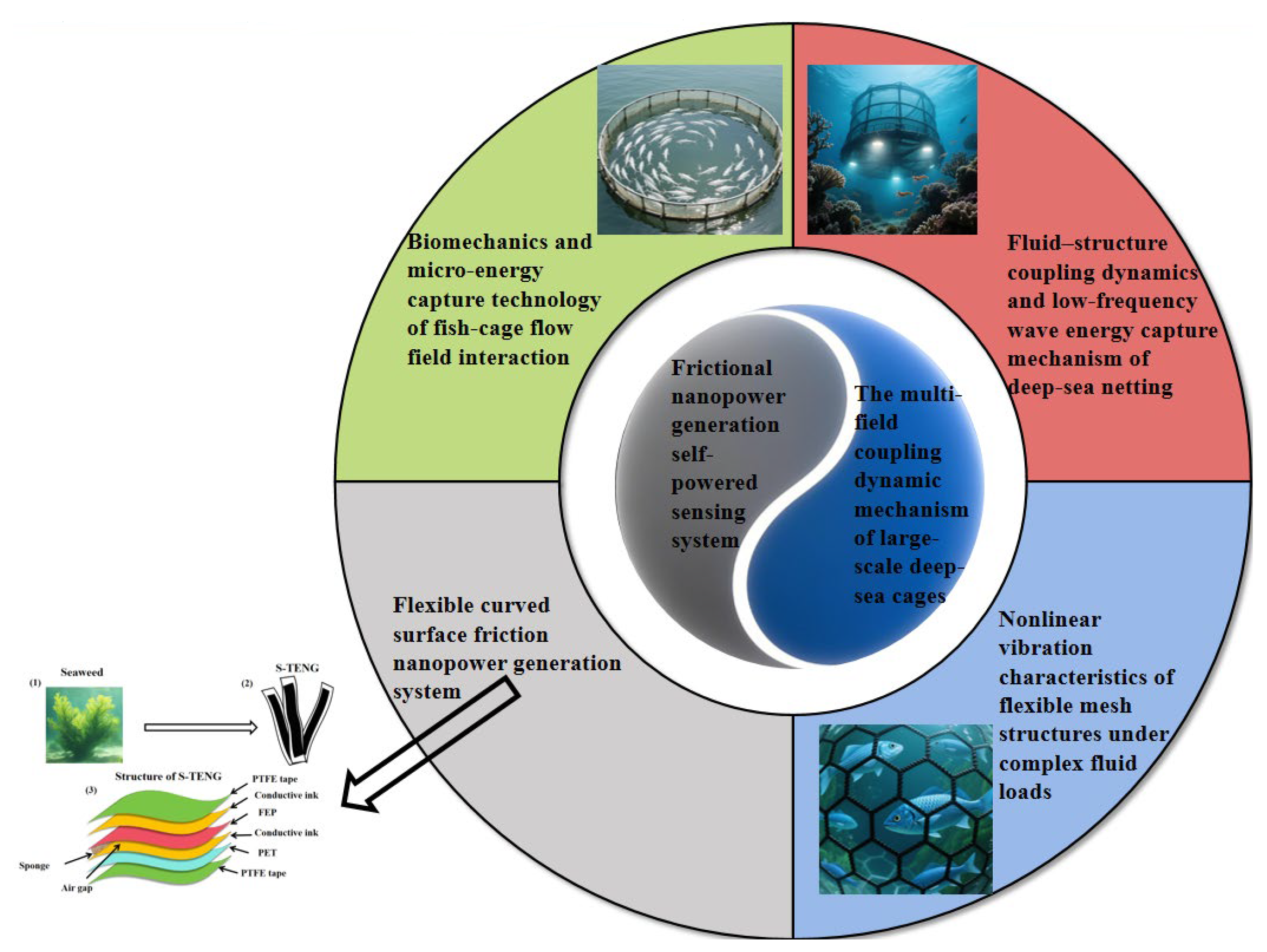
Figure 1. Schematic diagram of the technical field related to multi-field coupling dynamic mechanism and self-power supply system of deep-sea cages. (Among them, in the outer circle, the green area focuses on the biomechanics and micro-energy capture technology of flow field interactions in fish cages, the red area involves fluid–structure coupling dynamics and the low-frequency wave energy capture mechanism of deep-sea cages, the blue area discusses the nonlinear vibration characteristics of flexible net structures under complex fluid loads, and the gray area elaborates on the frictional nanopower generation system of flexible curved surfaces).
Jmse 13 02042 g001
Figure 2. Logical representation of the fluid–structure coupling dynamics of deep-sea net clothing and the defect of the low-frequency wave energy capture mechanism.
Jmse 13 02042 g002
Figure 3. The movement of the floating box: (a) surge; (b) floating and sinking; and (c) swaying. The data is sourced from [33].
Jmse 13 02042 g003
Figure 4. Deformation diagram of the net garment under load in complex Marine environments.
Jmse 13 02042 g004
Figure 5. The technical route for studying the correlation mechanism between resonance modes and energy accumulation.
Jmse 13 02042 g005
Figure 6. Schematic diagram of TENG’s flexible structure. ((1) Schematic diagram of seagrass swaying, (2) Schematic diagram of S-TENG, (3) structural schematic diagram of S-TENG). The image is sourced from [48].
Jmse 13 02042 g006
Figure 7. The logical presentation of designing a dynamically adaptable flexible TENG array: (a) Material–structure co-design: PDMS/AgNWs composite film is selected as the electrode material. The conductivity and flexibility are optimized by changing the concentration of AgNWs, and the surface is coated with polytetrafluoroethylene (PTFE) film to enhance the resistance to seawater corrosion. (b) Surface-adaptive structure optimization: Based on the “arc-shaped element—flexible connection” array configuration, the element curvature is matched with the surface of the mesh jacket. The element spacing is determined through finite element simulation. In the high-strain zone/edge of the mesh jacket, a serpentine electrode structure is adopted to enhance tensile reliability. (c) Low-frequency energy capture mechanism: By utilizing the contact–separation mode triggered by the low-frequency vibration of the mesh garment, the thickness and surface roughness of the friction layer are optimized, and the quantitative relationship between the output voltage, current, vibration amplitude, and frequency is established. The objective is to enhance the conversion efficiency of energy in the low-frequency band.
Jmse 13 02042 g007
Figure 8. (a) Volt–ampere characteristic curve, (b) tensile characteristic curve. The data is sourced from [52].
Jmse 13 02042 g008
Figure 9. (ac) Tensile cycling stability of the stretchable transparent electrode, (d) the multi-directional tensile performance of the stretchable transparent electrode. The data is sourced from [54].
Jmse 13 02042 g009
Figure 10. The logical presentation of the research content on energy transfer and cooperative capture of the multi-body cage coupling system under the combined action of wind, waves, and current.
Jmse 13 02042 g010
Figure 11. Dynamic stiffness as a function of mean load. The data is sourced from [61].
Jmse 13 02042 g011
Figure 12. (a) The relationship between the numbers C D and KC in pure wave fields and wave–current coexistence fields. (b) The relationship between the numbers C M and KC in pure wave fields and wave–current coexistence fields. The data is sourced from [65].
Jmse 13 02042 g012
Figure 13. Simulation results of regular waves and irregular waves. (a) Represents the diachronic curve of the height of the regular wave A, (b) represents the diachronic curve of the height of the regular wave B, (c) represents the irregular wave height diachronic curve, and (d) represents the spectrum of irregular waves. The data is sourced from [77].
Jmse 13 02042 g013
Figure 14. (a) Comparison of the force on the mesh jacket under different mesh size conditions, (b) comparison of the force on the mesh jacket under different wire diameter conditions. The data is sourced from [78].
Jmse 13 02042 g014
Figure 15. Schematic diagram of mechanical vibration modes.
Jmse 13 02042 g015
Figure 16. Logical presentation of the research content on biomechanics and micro-energy capture technology of the interaction between fish schools and cage flow fields.
Jmse 13 02042 g016
Figure 17. The thrust and lateral force throughout the fish’s body under different swimming conditions. The data is sourced from [101].
Jmse 13 02042 g017
Figure 18. Calculated results of Cxm with different St. The data is sourced from [103].
Jmse 13 02042 g018
Figure 19. (a) Schematic diagram of sensor wearing, (b) flowchart of sensor system operation.
Jmse 13 02042 g019
Table 1. The modulus value μ i of the Floquet multiplier is directly related to the vibration state of the net garment.
Modulus Value 0StatusVibration Amplitude
All μ i < 1 The net garment is in a steady-state vibrationThe vibration amplitude shows no increasing trend over time, and the dynamic behavior of the structure is controllable
When there is at least one μ i > 1 The system has entered the initial stage of instabilityThe vibration amplitude increases exponentially with the periodic iteration
When μ i = 1 The system is in a critical stable stateThe vibration amplitude remains constant but is prone to instability triggered by flow field disturbances
Table 2. Comparison of the adaptability of energy harvesting equipment in complex Marine environments.
Equipment TypeCapture Frequency RangePower DensityDeep-Sea Pressure Adaptation
(Maximum Water Depth)
Corrosion-Resistant LifeThe Adaptation Area of the Net BoxCore Advantage
Surface-adaptive TENG array0.1–10 HZ0.1–0.5 mW/cm21500 m6 to 12 monthsThe curved surface and floating body of the net garmentFlexible conformal, low-frequency adaptation
Deep-sea compatible EMG0.5–50 HZ5–15 mW/cm22000 m5 years and moreFrame, anchor chainHigh-power and high-voltage tolerance
Flexible PEH50–100 HZ0.5–12 mW/cm21000 m2 years and moreLocal areas of the net garment and turbulent zonesHigh-frequency capture, flexible integration
Bionic multimodal integrated system0.1–500 HZ2–8 mW/cm21800 m3 years and moreFull net box coverageFull-band capture and strong environmental adaptability
Table 3. Comparison table of power and energy consumption characteristics of core equipment for deep-sea aquaculture.
Equipment CategorySpecific EquipmentPower RangeWorking ModeAverage Daily Power Consumption
(Wh)
Structural monitoring sensorStrain sensor5–15 μWIntermittent sampling (once per minute)0.012–0.036
Vibration sensor10–20 μWIntermittent sampling (once per 30 s)0.024–0.048
Acceleration sensor8–12 μWIntermittent sampling (once/2 min)0.0096–0.0144
Environmental monitoring sensorTemperature sensor3–8 μWContinuous monitoring (once per 10 s)0.0216–0.0576
Salinity sensor15–25 μWIntermittent sampling (once for 5 min)0.0432–0.072
Dissolved oxygen sensor30–50 μWContinuous monitoring (once per 5 s)0.432–0.72
pH sensor20–35 μWIntermittent sampling (once/2 min)0.0576–0.1008
Execution deviceAutomatic feeding machine10–30 WIntermittent work (three times a day, 10 min each time)5–15
Underwater camera50–100 mWIntermittent shooting (1 h each day)0.05–0.1
Data transmission systemShort-range wireless transmission module50–100 mWIntermittent transmission (once per 10 min)0.072–0.144
Long-range wireless transmission module1–5 WIntermittent transmission (once per hour)0.04–0.2
Auxiliary systemWater quality regulating pump5–15 WIntermittent work (twice a day, 30 min each time)5–15
Biological cleaning device8–20 WIntermittent work (once a day, 20 min each time)2.67–6.67
Table 4. A comparison table of the adaptability of different energy capture technologies in deep-sea aquaculture scenarios.
DimensionsSurface-Adaptive TENG ArrayUnderwater Solar EnergyElectromagnetic EMG
Power density0.1–0.5 mW/cm2<0.01 mW/cm25–15 mW/cm2
Adaptation frequency0.1–10 Hz (low)The deep sea is ineffective0.5–50 Hz (medium to high)
Environmental tolerance1500 m water pressure, corrosion-resistant for 6 to 12 monthsEasy to adhere, with a 50% reduction in effectiveness in March2000 m water pressure, corrosion resistance for over 5 years
Conversion efficiency15–20% (low frequency)<1% (deep sea)40–50% (mid and high frequencies)
AdaptabilityFlexible mesh fabricIt takes up space and is not usable in the deep seaA fixed frame is required
Unit cost0.02 dollar/Wh0.8 dollar/Wh0.08 dollar/Wh
Table 5. Parameters for calculation. The data is sourced from [103].
Different Incoming Flow Velocity Operating ConditionsOperating Conditions with Different Swing FrequenciesWorking Conditions with Different Lateral Movement Amplitudes
Serial NumberV/
(m·s−1)
A/C0f/HzStSerial NumberV/
(m·s−1)
A/C0f/HzStSerial NumberV/
(m·s−1)
A/C0f/HzSt
10.80.60.50.3051.20.60.250.1091.20.40.50.13
21.00.60.50.2461.20.60.50.20101.20.60.50.20
31.20.60.50.2071.20.60.750.30111.20.80.50.27
41.40.60.50.1781.20.610.40121.210.50.33
Table 6. Comparison of calculation results from different grid schemes.
Grid SchemeCore Domain SizeTotal Resistance (N)Internal Flow Velocity (m/s)Fine Grid Error
Coarse grid5 cm1850.2812.3%
Middle grid3 cm2050.324.7%
Fine grid1 cm2150.330%
Disclaimer/Publisher’s Note: The statements, opinions and data contained in all publications are solely those of the individual author(s) and contributor(s) and not of MDPI and/or the editor(s). MDPI and/or the editor(s) disclaim responsibility for any injury to people or property resulting from any ideas, methods, instructions or products referred to in the content.