Abstract
The severe vertical motion of high-speed multihull vessels significantly impairs their seakeeping performance, making the design of effective anti-motion controllers crucial. However, existing controllers, predominantly designed based on deterministic dynamic models, suffer from limitations such as insufficient robustness, reliance on empirical knowledge, structural complexity, and suboptimal performance, which hinder their practical applicability. To address this, this paper proposes a robust decoupled vertical motion controller based on the step response inversion method and incorporating an Extended State Observer (ESO) uncertainty compensation term. The control algorithm is designed leveraging the equivalent noise bandwidth theory to account for the stochastic characteristics of pitch/heave motion, with ESO compensation introduced to enhance robustness. The stability of the closed loop system is rigorously proven through theoretical analysis. Simulation results demonstrate that the proposed algorithm significantly suppresses the amplitudes of both pitch and heave motions.
1. Introduction
Due to the rapid development and close interconnection of the global economy, the urgent demand for fast and efficient marine transportation has motivated increasing research on large vessels capable of high speed and maneuverability for both military and civilian use [1]. One significant trend in high-speed construction is the multihull [2]. The multihull is a newly developed kind of vessel that is different from a conventional monohull. As can be seen from the nomenclature, multihull usually represents a type of surface vessel that uses two or more slender hulls at a certain distance and connected by the cross-deck structure, e.g., a catamaran with two hulls and a trimaran with three hulls, as illustrated in Figure 1. Due to the unique hull structure, the multihull has many advantages such as a large deck area and loading capacity, a relatively large ratio of deadweight to displacement, good seakeeping performance, and high hydrodynamic stability. However, due to the slender hull geometry and high Froude number of high-speed multihulls, excessive vertical motions of heave and pitch can occur. The excessive vertical motions can result in the seasickness of passengers and crew members, bow slamming, structural hull damage, and even the loss of speed. These adverse effects can deteriorate the efficiency of the multihull’s performance and bring about a great threat to navigation security. Thus, it is necessary to adopt some effective measures to control and mitigate the excessive motions to a tolerable level.
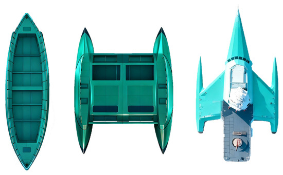
Figure 1.
Monohull, catamaran, and trimaran comparison. Monohulls exhibit pendulum-like motions characterized by large amplitudes and low frequencies. In contrast, catamarans achieve high initial stability through a wide beam, which minimizes roll. However, this configuration can result in sharper, higher-frequency accelerations. The trimaran configuration integrates a central hull with two outrigger floats, thereby combining the seakeeping performance of a monohull with the inherent stability of a catamaran. This hybrid design offers balanced and superior motion characteristics across a wide range of sea conditions.
Considering the relatively advanced design and the resources and time required for hull design, anti-pitching appendages have become a popular way to further improve the performance and reduce excessive vertical motion. The combination of anti-pitching appendages such as a T-foil and flap has been generally used. A T-foil mounted on the centerline at the aft end of the bow can effectively increase the longitudinal damping of the multihull during operation, such that the amplitudes of heave and pitch motions can be reduced compared with the original motions without applying an anti-pitching appendage. On this basis, the utilized flap located at the stern can improve the motion’s attitude so as to reduce the vessel’s resistance. It is worth mentioning that an inactive anti-pitching strategy adopting appendages with fixed angles of attack can slightly reduce the vessel’s motion; however, in order to further increase this reduction, active control must be introduced into the anti-pitching appendages’ control system. To design the control system, a number of well-developed and advanced methods can be adopted for the vertical stabilization of a high-speed multihull [3]. The angles of attack of the T-foil and flap can then be automatically adjusted with changes to the state of the system and in real time during the navigation, and the required restoring force and moment generated by the used anti-pitching appendages can be significantly increased to counteract the wave-induced force and moment, resulting in the improvement of anti-pitching performance.
In contrast with other hot-ticket control problems for marine vessels, such as path following and trajectory tracking [4,5], the control of vertical stabilization for multihulls had a late start. Although this research area has been receiving growing interest from both academic scholars and practical engineers, there has been a limited number of publications on this issue to date. Referring to the coupled vertical motion model of high-speed multihulls, a proportional differential (PD)-based vertical stabilization control method was designed by the authors of [6]. While effective under idealized conditions, this approach suffers from a critical reliance on precise hydrodynamic coefficients, rendering its performance limited and its robustness poor in the face of practical-model uncertainties.
To address unmodeled dynamics, the fuzzy control method was proposed in [7]. However, as a model-free approach, its performance heavily depends on expert knowledge and extensive tuning, and it lacks formal stability guarantees, which may raise concerns in safety-critical marine applications.
To enhance robustness against model variations, a high-order quantitative feedback control method was employed in [8]. A key limitation of this method is that its design is based on the worst-case scenario, often leading to conservative controller performance that may not fully exploit the system’s capabilities in typical operating conditions.
A common thread among these aforementioned studies is their treatment of disturbances primarily as deterministic or bounded uncertainties. None of them explicitly account for the stochastic nature of wave-induced loads. This gap means that their controllers lack a mechanism to optimally attenuate the random, zero-mean components of wave forces, which are predominant in irregular seas. This study seeks to address this gap.
Aside from theoretical analysis and numerical simulation research, some experimental investigations on the vertical stabilization of high-speed multihull have been reported in recent years. The research group from Spain contributed to the pioneering work about the reduction in seasickness incidence [6].
In [9], considering a variety of criteria including slamming, global loads, and motions, several motion control algorithms were developed. It was claimed that using the most effective pitch control mode, global loads, and motions were significantly reduced under the condition of smaller wave significant height, and the pitch reduction performance was the most significant in the nonlinear mode. The work by Alavimehr et al. provides valuable insights. In a series of systematic experimental studies [10,11], they investigated the effects of various seakeeping control algorithms—including those for local motion, heave, and pitch control, as well as their linear and nonlinear variants—on the motion responses and structural loads of a 1:44.8-scale hydroelastic segmented model of a 112 m high-speed wave-piercing catamaran. Their findings demonstrated that the pitch control mode exhibited the highest effectiveness. In waves with a model-scale height of 60 mm, compared to the bare hull without a seakeeping control system, it achieved a significant 90% reduction in the peak slamming force and a 75% decrease in the average slamming-induced bending moment. These experimental data fully validate the substantial potential of active seakeeping control systems in mitigating wave-impact loads on high-speed catamarans, while also providing a valuable experimental validation benchmark for the design of control algorithms. Furthermore, Tavakoli et al. explored adaptive control strategies for marine vehicles under uncertain wave disturbances, highlighting the importance of robust observer-based control in improving system performance [12]. While these studies have advanced the understanding of motion control in deterministic or passive settings, the incorporation of stochastic wave dynamics into controller design remains less explored, which motivates the present study. In order to mitigate the excessive vertical motions, the systematic design from the selection of adopted anti-pitching appendages to motion reduction control algorithm were proposed in [12]. The effectiveness of the proposed design method was demonstrated in both numerical simulation and the experimental test. The longitudinal motion characteristics of a slender trimaran with or without T-foil mounted near the bow were investigated through both theoretical and practical methods. The seakeeping characteristics were analyzed in head sea with various wave conditions, and a reasonable agreement of numerical results and experimental data was validated in [13].
All aforementioned articles have made important contributions to the design of vertical stabilization control of high-speed multihull and, as observed from papers discussed above and others not listed here, the stochastic characteristic of the external wave disturbances have not been particularly studied. The control performance can deteriorate or even the system instability can occur if the stochastic components of the sea loads induced by external waves are neglected. This situation indicates that there still exists the potential of obtaining the robust controller to reduce the excessive vertical motions under the environmental disturbance wave of stochastic nature.
Furthermore, it is worth examining the methodological choice in the context of other emerging approaches, particularly data-driven machine learning (ML). The rise of ML has inspired its application in seakeeping for system identification and control, offering potential in modeling complex, nonlinear dynamics [14]. However, such methods face significant complications for real-time control applications such as those addressed in this study. As highlighted by Majidiyan et al., the inherent stochasticity of environmental data (waves, wind) presents a fundamental challenge, as ML models often require structured input and can struggle with the unstructured, ensemble nature of real-world sea states. Deploying a reliable “black-box” ML model onboard would necessitate extensive training data covering a vast range of probabilistic scenarios, considerable computational resources for training, and robust strategies for uncertainty quantification to ensure safety—challenges that are non-trivial to overcome. In contrast, the model-based ESO-backstepping control strategy proposed in this work embeds prior physical knowledge of the ship dynamics. It explicitly addresses stochastic disturbances through theoretical frameworks such as the Wiener process and Lyapunov stability analysis, ensuring robustness and guaranteed performance without dependence on large datasets. Therefore, while ML presents a promising avenue for future research, the proposed methodology offers a more direct, interpretable, and certifiable solution for the critical task of vertical motion stabilization in stochastic seas.
The principal novelty and advancement of this work beyond previous robust/adaptive controllers are threefold. (1) A Stochastic Dynamics Framework: While prior robust controllers (e.g., [8]) or fuzzy logic approaches [7] primarily addressed bounded uncertainties or deterministic disturbances, they lack a formal mechanism to handle the inherent stochasticity of wave excitations. This work advances the field by explicitly modeling wave-induced forces as a Wiener process, moving beyond deterministic or bounded-uncertainty assumptions. This provides a more realistic foundation for controller design in irregular seas. (2) A Decoupled Estimation-and-Control Architecture: Unlike standard adaptive controllers that may intertwine parameter estimation with control law synthesis, the proposed approach introduces a clear decoupling: The ESO is dedicated to the real-time estimation of the entire lumped disturbance (including both stochastic and deterministic parts), while the backstepping controller utilizes these estimates. This architecture not only simplifies the control law derivation but also enhances modularity, allowing for future upgrades to the observer independently of the controller. This represents a structural advancement over more monolithic adaptive control designs. (3) Guaranteed Stochastic Stability: The most significant theoretical advancement is the rigorous proof of closed loop stability in probability using stochastic Lyapunov theory. Most existing applied studies on multihull control demonstrate performance only via simulation or experiment. By contrast, the present study provides a mathematical guarantee of stability for the stochastic nonlinear system, addressing a fundamental limitation in the theoretical underpinnings of many prior approaches.
This paper is organized as follows. In Section 2, the vertical mathematical model with the applied anti-pitching appendages is presented. In Section 3, the disturbance observer is designed. In Section 4, based on the stochastic control and stability theories provided in Appendix A, the robust controller is designed with the combination of disturbance observer. The numerical simulations are provided in Section 5, validating the effectiveness of the proposed control design. At last, the conclusions are summarized in Section 6.
2. Mathematical Model
It is assumed that the multihull has a symmetrical xz-plane, i.e., the hull is symmetrical with respect to the vertical middle section, and there exists no coupling between the lateral and vertical motions. The restoring force and moment produced by anti-pitching appendages T-foil and flap can be utilized to counteract stochastic wave disturbance, such that the severe motions of the heave and pitch can be mitigated [15].
The heave and pitch motions of the high-speed trimaran investigated in this study are primarily excited by incident waves with wavelengths comparable to the vessel length. Under the condition of infinite water depth, the reflection and dissipation effects of the seabed on surface waves can be neglected—this simplification of the wave dispersion relation allows for a focused analysis of the fundamental interactions between the hull and waves. The core research objective of the present study is to suppress the high-frequency vertical motions (i.e., heave and pitch) induced by first-order wave forces. In contrast, the forces generated by wind loads and ocean currents are typically low-frequency or quasi-static in nature; these forces primarily influence the ship’s course keeping, speed regulation, and horizontal positional stability (encompassing surge, sway, and yaw motions). To maintain a concentrated focus on the core control challenges within the vertical plane, these low-frequency disturbances are excluded from the current analysis.
Assume that the multihull operates on the infinite deep water without the consideration of the effects of wind and current. The underwater segment of the hull is sufficiently slender and long such that the strip theory can be adopted to obtain the hydrodynamic coefficients, and the wave-induced motion is relatively small.
It should be noted that the classical strip theory employed here, based on the slender-body assumption, calculates the hydrodynamic forces by discretizing the hull into independent two-dimensional sections. This approach does not account for the complex three-dimensional hydrodynamic interactions between the adjacent demihulls of a trimaran (e.g., wave-making interference), which inevitably introduces certain deviations from reality. However, for the heave and pitch motions of the high-speed trimaran in waves under consideration, existing studies suggest that the influence of demihull interaction on the main hull’s hydrodynamics is of secondary importance within the primary frequency range of interest. Given that the primary focus of this paper is to validate the effectiveness of the proposed control strategy for anti-pitching appendages, the application of the well-established strip theory to obtain baseline hydrodynamic coefficients is considered a reasonable and efficient engineering simplification.
Generally speaking, the vertical forces and moments mainly include the buoyancy, the lifting force and moment due to the advance speed, the control forces and moments generated by actively operated anti-pitching appendages, and stochastic wave-induced disturbance force and moment. The mathematical model of heave–pitch dynamics for high-speed multihull can be described in the coordinate systems illustrated in Figure 2.
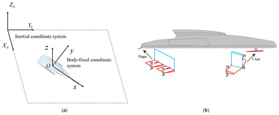
Figure 2.
High-speed multihull. (a) Fixed-body coordinate; (b) the T-foil and flaps.
The longitudinal dynamic equations for multibody ships can be expressed as follows:
where represents longitudinal oscillation velocity, represents hull longitudinal oscillation force, represent longitudinal oscillation force components generated by T-wing and flaps, and represents wave-induced longitudinal oscillation disturbance force.
Within the time scale of the control design, longitudinal oscillation velocity changes relatively slowly and can therefore be regarded as a quasi-steady parameter in the pitch–roll controller design [2]. However, a complete system model should incorporate longitudinal oscillation dynamics to ensure physical consistency.
Considering the longitudinal center of gravity as the origin, a nonlinear mathematical model of heave–pitch dynamics of the multihull can be established based on the rigid body momentum theorem and moment of momentum theorem:
where is the mass of the multihull, is the acceleration along the direction , is the acceleration term (similar to the Coriolis acceleration) due to the ship’s forward speed and the pitch angular velocity , is pitch angle. and denote the forces generated by T-foil and flap, respectively. is the lift force generated by the hull due to forward speed, and is the buoyancy of multihull. represent the distance between longitudinal center of gravity and midship. and denote the distances from the lifting point and buoyancy point to the midship, respectively. and are the stochastic wave-induced force and moment. and represent the moments provided by T-foil and flap, respectively. The forces and moments produced by T-foil and flap can be obtained by
where is the water density. , , and , are the planform areas and force arms of flap and T-foil area, respectively. and are the lifting coefficients of T-foil and flap, respectively. is the ship speed. , denote the angles of attack of flap and T-foil, respectively. In the other aspect, it can be concluded that the required attack angles of anti-pitching appendages can be transformed through the demanded control force and moment.
Due to the influence of hull geometric symmetry and forward speed, significant coupling exists between heave, pitch, and roll motions. Changes in heave velocity affect the hydrodynamic coefficients of pitch and roll, roll motion generates additional drag in the heave direction, and pitch motion influences heave through wave-making resistance.
As can be seen from the dynamic model described in (2), in addition to the strong nonlinearity, the hydrodynamic coefficients of added mass and damping are time-varying. Thus, the linearization process is necessary to facilitate the engineering implementation, and the nonlinear model (2) can be generally formulated as
where is the system state of the high-speed multihull. , , , and denote the heave velocity, pitch angular velocity, heave displacement, and pitch angle, respectively. represents the control input. At the equilibrium point of original nonlinear control system, the first-order Taylor expansion method can be adopted to obtain
where is the infinitesimal of higher order, and
The obtained equation can be further simplified as
where is the ship mass, and is the moment of inertia with respect to the longitudinal axis . and denote the added mass and moment of inertia, respectively. , and , are the coefficients of damping and restoring forces, respectively. , , , , , are the coupling coefficients of vertical forces and moments. For example, is the coefficient of added mass for heave motion due to pitch motion, and denote the coefficient of added mass for pitch motion due to heave motion. Based on the strip theory proposed in [16] or computational fluid dynamic software, these aforementioned hydrodynamic and hydrostatic coefficients can be obtained. It is worth mentioning that the model test can also be utilized to obtain these coefficients, but this method is relatively rarely adopted due to the massive costs. and denote the deviations in heave and pitch motion models induced by linearization.
From (13), it can be clearly seen that the coupling exists in pitch and heave motions of high-speed multihull, and the obtained system coefficients have strong uncertainties. Moreover, the model parameters can vary under the condition of different speed and encounter frequency. It can be referred from [17] that stochastic wave-induced force and moment term usually consisted of 1st-order (zero mean) and 2nd-order (mean wave drift load) wave forces; thus, in general, the terms and contain constant and stochastic components, which can be described as
where , and , represent the constant and stochastic components of wave-induced force and moment , respectively. On this basis, the standard Wiener process can be used to describe the stochastic part of wave-induced disturbance. Then, it can be defined as
where denotes the Wiener process, and the dot represents the time derivative. represents the covariance which is time varying. Substituting (16) into (13), the stochastic differential equations for vertical motion control can be obtained as
where and denote the control inputs of force and moment produced by the adopted two anti-pitching appendages T-foil and flap.
For the convenience of the multivariate control design, the two decoupled vertical motion models of heave and pitch motions can be derived. Define , as the heave displacement and heave velocity, and , as the pitch angle and pitch angular velocity. Referring to the coupled vertical motion model (17), the decoupled heave motion model can be described as
where denotes the combination of constant component of wave-induced disturbance force, and the disturbance force produced by coupled pitch motion. can be considered as the uncertainty term of the decoupled heave motion model.
In order to facilitate the subsequent observer and control design, the decoupled heave motion model described in (18) can be further formulated in the following general expression as
where denotes the nominal model of heave motion, and represents the lumped disturbance term in the heave motion control system. and are the control gain and control input, respectively.
Similarly, with the same denotation and mathematical manipulation, the decoupled pitch model can be further described in a more general formulation as
where denotes the nominal model of pitch motion. denotes the combination of constant component of wave-induced disturbance moment, as well as the disturbance moment produced by coupled heave motion. can be considered as the uncertainty term of the decoupled pitch motion model. represents the lumped disturbance term in the pitch motion control system. and are the control gain and control input, respectively.
Remark 1.
Roughly speaking, and represent the mean value of stochastic wave-induced force and moment, respectively. If is bounded or the stochastic term is ignored, the decoupled heave motion model (19) and pitch motion model (20) become the deterministic control system. Many existing robust control methods and controllers proposed to handle this kind of deterministic system [18] can be directly adopted to ensure the system stabilization. However, with the consideration of the stochastic component of wave-induced force and moment, these controllers cannot be applied due to the deteriorated control performance or even system instability.
The control objective of this study is to design a stochastic robust decoupled anti-vertical motion controller, comprising disturbance compensation and a robust adaptive control term, aimed at mitigating excessive heave and pitch motions. To illustrate the proposed motion suppression control methodology, the decoupled control diagram is presented in Figure 3. A disturbance observer is employed to estimate the lumped disturbance within the decoupled control model for heave and pitch motions, thereby enhancing control robustness through feedforward compensation. Furthermore, leveraging a reference stochastic motion model, the robust adaptive control term is designed using the backstepping method, deriving update laws for estimating both the constant and stochastic components of the wave-induced forces and moments, consequently improving vertical motion suppression performance.
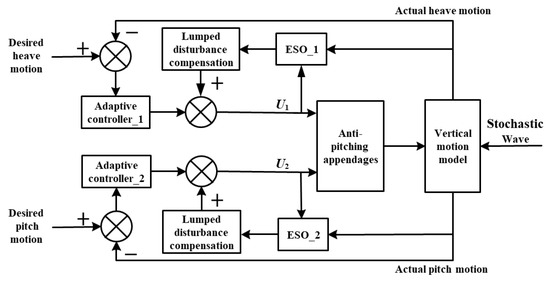
Figure 3.
The proposed anti-pitching control diagram.
The decoupled design of the Extended State Observer (ESO) compensation module and the backstepping control module serves as a pivotal enabler for realizing “stochastic disturbance adaptation”. ① The ESO compensation module is dedicated to “disturbance estimation”: it achieves this by decomposing the deterministic and stochastic components of wave-induced disturbances and thereafter delivers real-time compensation signals and covariance information. This design thereby overcomes the inherent limitation of conventional backstepping control—namely, its neglect of the statistical properties of disturbances. ② In contrast, the backstepping control module centers on “control law optimization”. Leveraging the desired trajectory and the disturbance information furnished by the ESO, it formulates virtual control laws and actual control commands in a hierarchical fashion. This approach effectively precludes the logical ambiguity that would arise from conflating “disturbance estimation” with “control computation”. Notably, this decoupled design not only guarantees the independence of disturbance estimation (facilitating the subsequent integration of more advanced observer architectures) but also streamlines the complexity associated with control law derivation, ultimately enhancing the scalability of the overall control framework. Figure 4 shows the hydrodynamic coefficients of the trimaran.
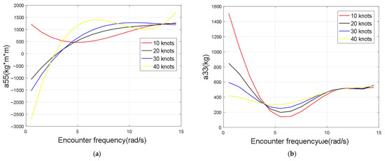
Figure 4.
Hydrodynamic coefficient effects [2]. (a) Encounter frequency and coefficient ; (b) Encounter frequency and coefficient .
3. Disturbance Observer Design
Due to the existing lumped disturbance, which consist of decoupling term, constant component of stochastic wave disturbance, and unmodeled error, the control law obtained using the nominal control system cannot eliminate the steady state error so as to cause the bad performance and poor robustness. Based on the separation principle, the disturbance estimation design can be conducted independently of the control design; thus, the disturbance observer is adopted to estimate the lumped disturbances of decoupled motion control models of heave and pitch. The disturbance compensation strategy has been widely used in many areas, and in order to estimate the lumped disturbance of decoupled heave motion model, the adopted disturbance observer can be formulated as
where denotes the desired value of the observed output, i.e., lumped disturbance , and is the estimated value of . is the observer gain. Dot represents the normal time derivative.
Referring to the decoupled heave motion model (19), the lumped disturbance can be obtained as
where the obtained lumped disturbance is the desired value of defined in (21). Substituting (22) into (21), it can be formulated as
Defining the auxiliary observer state as , the lumped disturbance can be derived as
Substituting (24) into (23), the observer can be obtained and formulated as
The block diagram of the disturbance observer described in (24) and (25) is shown in Figure 5. In order to achieve the accurate estimation, the disturbance estimation should be close to the actual lumped disturbance as much as possible. Equivalently, the deviation should tend to be zero. The time derivative of the defined estimation error can be written as
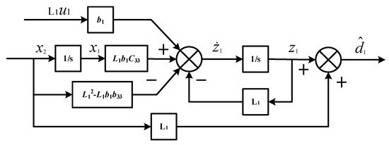
Figure 5.
The disturbance observer diagram.
The motion state of high-speed multihull consists of the low-frequency and high-frequency motion, and the latter can only cause slight motion with a nearly unchanged position. Only the low-frequency motion is considered in this paper; thus, the lumped disturbance is assumed to be unchanged during the sampling periods of onboard sensors. The candidate Lyapunov function of the adopted disturbance observer can be selected as
Then, the derivative of the chosen Lyapunov function can be obtained as
where the observer gain should be properly chosen as , after which the condition can hold such that the convergence of the used disturbance observer can be ensured.
The forward compensation control for the decoupled heave motion model can be given by
Similarly, the disturbance observer used for the decoupled pitch model can be formulated as
where denotes the desired value of the observed output in the pitch model, i.e., lumped disturbance , and is the estimated value of . is the observer gain.
Considering the decoupled pitch motion model (20), the lumped disturbance can be obtained as
where the obtained lumped disturbance is the desired value defined in (30). Substituting (31) into (30), it can be formulated as
Defining the auxiliary observer state as , the lumped disturbance can be derived as
Substituting (33) into (32), the observer can be obtained and formulated as
Except for different denotations, the block diagram of the disturbance observer described in (33) and (34) is mostly the same with Figure 5, thus its omission here. The forward compensation control for the decoupled pitch motion model can be given by
Remark 2.
It can be obviously seen from (21) and (30) that the actuator deflection is positively associated with the observer gain, and the large gain can cause the much fast control movement which can be beyond the operation range.
4. Control Design
Considering the decoupled heave motion model (19) and pitch motion model (20), the simple generalized formulation is a kind of cascade structure with strict feedback form. Thus, the popular control method backstepping control strategy can be utilized for the control design to achieve the control objective. The control design for the decoupled heave motion model (19) is first considered and can be divided into two steps. Referring to the first equation of the heave motion model, the heave velocity can be used as the virtual control to stabilize the difference between the heave displacement and desired value at the origin in probability. In the second and last step of the control design for the heave motion model, the control input can be designed to stabilize the error between the heave velocity and its virtual control designed in the first step at the origin in probability. The control design process of the decoupled pitch motion model is basically the same except for different denotations.
Let and be the errors of the heave displacement and heave velocity, respectively, where denotes the virtual control of the heave velocity . As the adaptive control objective is to mitigate the excessive vertical motions of high-speed multihull, the desired heave displacement can be assumed to be zero, i.e., . Differentiating both sides of the error between the heave displacement and its desired value, it can be obtained that
Then, the virtual control should be designed so as to stabilize the error (36) at the origin. Due to the Hessian terms in the infinitesimal generator described as (A3), the quartic form of the candidate Lyapunov function is used instead of the common quadratic form normally adopted in the control design, and can be formulated as
Differentiating both sides of (37), the infinitesimal generator can be obtained as
where the virtual control can be chosen as . Substituting the virtual control into (38) and (36) yields the following:
Taking into account the second equation of the decoupled heave motion model, the candidate Lyapunov function can be chosen as follows:
Referring to (A3), differentiating both sides of (41), the infinitesimal generator can be obtained as
where the time derivative of is represented by , and the second order partial derivative is
Using the Young’s inequality, the following inequalities can be derived as
Then, (42) can be rewritten as follows:
where the constant should be strictly positive, i.e., , then the control input can be chosen as
where is a strictly positive constant with .
Substituting (48) into (47) yields the following:
Based on (48), the error dynamics of the heave velocity can also be obtained as:
It is assumed that the lumped disturbance and unknown time varying covariance are both bounded, such that the condition and can be satisfied. Then, (49) can be rewritten as
where , , , and . Using Theorem A1 yields the following:
The expectation of the existing unique strong solution of the closed system (40) and (50) can be further obtained as
It can be obviously seen that the constant can be arbitrarily large by choosing sufficiently large and , resulting in the sufficiently small value of .
Theorem 1.
If the assumptions that the lumped disturbance and unknown time-varying covariance are both bounded, i.e., and , can be satisfied, and there exist the constants , , and the designed control law (48), such that the closed loop system consisting of (40) and (50) has a unique strong solution. Furthermore, the expectation of the existing solution can converge to an arbitrarily small value as described in (53) if choosing sufficiently large values of and .
Referring to Theorem 1, the designed control law (48) can make the expectation of the unique strong solution of the closed loop system arbitrarily small, but the Young’s inequalities used in (45) and (46) make the designed controller conservative, resulting in limited control performance. In order to reduce conservatism, the update law of the assumed bounded variables and should be designed.
Let and , where , and and denote the estimation and estimation error of the variable, respectively. The candidate Lyapunov function can be chosen as follows:
where is symmetric and positive definite, and is a positive constant, i.e., .
Differentiating both sides of (54), the infinitesimal generator can be obtained as:
Using the Young’s inequality for the term , it can be derived as
Substituting (44) and (56) into (55) yields the following:
where .
Using the projection algorithm formulated in Definition A4, the control input , and update laws of the estimated values and can be chosen as
where is a positive constant.
Referring to the third derived condition of the projection algorithm, i.e., , substituting (58) and (59) into (57) yields
Based on (58) and (60), the error dynamics of the heave velocity can also be obtained as
Analogous to (51), (60) can also be rewritten as
where
Using the first condition given in Definition A4 yields , and , where denotes an arbitrarily small positive constant, then it can be obtained that
Substituting (64) into (63), it can be obtained that
Referring to (65) and Theorem A1, it can be concluded that the closed loop system consisting of (40), (58), (59), and (61) has a unique strong solution. Different from Theorem 1, the designed controller formulated in the first equation of (58) and (59) cannot make the expectation of the existing solution exponentially converge to an arbitrarily small value, but make the expectation of the defined error function convergent to the value described as .
Recalling (54), the candidate Lyapunov function can be rewritten as
where and . It can be clearly seen that the function is a function of .
According to the right side of (60), let , and it can be concluded that the defined function is a strictly increasing function, as the coefficients and are chosen such that the conditions and hold. Thus, there exists functions and such that and , where . Referring to (60), it can be rewritten as , and then it can be obtained as .
Applying Theorem A2 yields the following:
Theorem 2.
If the assumptions that the lumped disturbance and unknown time varying covariance are both bounded, i.e., and , can be satisfied, and there exist the constants , , and the designed control law formulated as the equation of (58) and (59), such that the closed loop system consisting of (40), (58), (59) and (61) has a unique strong solution. Furthermore, the defined error function can converge to an origin centered ball in probability as described in (67).
5. Numerical Simulations
5.1. Simulation Setup and Parameters
The trimaran scale information used in the simulation is shown in Table 1. The wave excitation forces and moments across a range of frequencies are calculated using a modified strip theory method. Subsequently, the time-domain realizations of these disturbances are constructed via data fitting and superposition techniques.

Table 1.
Tribody ship owner’s dimensions.
In the numerical simulations, the wave can be simulated by P-M spectrum formulated as
where is the average wind speed at the height of 19.5 m above the sea surface, and denotes the acceleration of gravity.
The full-scale multihull speed is set to be 40 knots in head sea with the encounter frequency 3.25 rad/s. The wave parameters are shown in Table 2.

Table 2.
Wave simulation parameters.
5.2. Results and In-Depth Analysis
The results in the present study were analyzed by (i) computing the time histories of pitch and heave motions for the ship model under PID control and heave motion control, and (ii) computing the root mean square () and reduction efficiency ratio . The is a measure representing the ensemble statistic of a stochastic time series. For a given time series , its is defined as
where is the mean value of , and represents the number of the time series.
With the definition of , the reduction efficiency ratio, , is formulated into
in which is the root mean square of the ship model’s motion under PID control, while is the root mean square of the ship model’s motion under heave motion control.
Figure 6, Figure 7, Figure 8, Figure 9, Figure 10 and Figure 11 depict the heave and pitch responses across significant wave heights from 0.1 m to 0.6 m. The proposed controller consistently reduces the peak-to-peak amplitude of heave displacement compared to the PID controller. Notably, as wave height increases, the suppression of large-amplitude motions becomes more pronounced, indicating effective compensation for stronger nonlinear disturbances. As can be seen from Figure 6, Figure 7, Figure 8, Figure 9, Figure 10 and Figure 11, a significant reduction in pitch angle is observed, particularly under higher sea states. This confirms the efficacy of the decoupling control design in managing the coupled pitch motion.
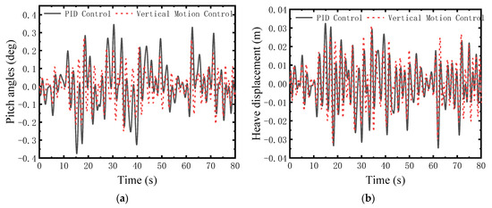
Figure 6.
Comparison at sea state 1. (a) Heave displacement; (b) Pitch angle.
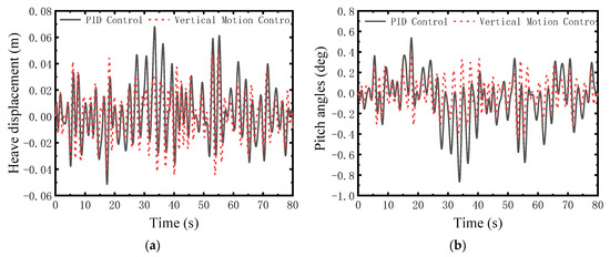
Figure 7.
Comparison at sea state 2. (a) Heave displacement; (b) Pitch angle.
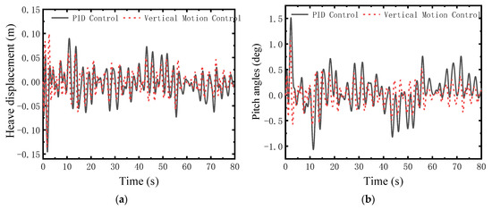
Figure 8.
Comparison at sea state 3. (a) Heave displacement; (b) pitch angle.
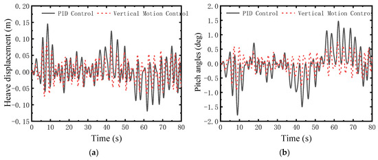
Figure 9.
Comparison at sea state 4. (a) Heave displacement; (b) Pitch angle.
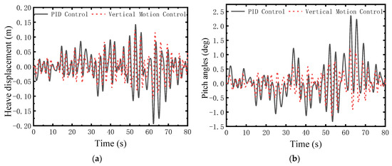
Figure 10.
Comparison at sea state 5. (a) Heave displacement; (b) Pitch angle.
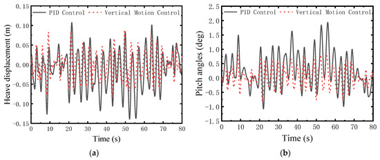
Figure 11.
Comparison at sea state 6. (a) Heave displacement; (b) Pitch angle.
The proposed controller exhibits shorter settling times and significantly lower transient overshoots compared with PID control. This indicates a faster recovery capability under sudden disturbances and a more reliable motion stabilization effect.
Beyond amplitude reduction, the proposed controller also alters the phase relationship between input disturbance and output response. Time-domain comparisons demonstrate that it reduces phase lag in heave motion, allowing the vessel to realign more rapidly with wave excitation. This behavior aligns with the control law structure, in which the ESO provides timely disturbance estimates, effectively diminishing system delay. Such phase characteristics contribute directly to improved ride comfort and reduced structural loads by minimizing out-of-phase excitation.
Remark 3.

The reduction values in Table 3 are statistically reliable due to rigorous simulation design, for two key reasons:

Table 3.
Reduction ratios of motion RMS for vertical motion control in irregular waves (%).
Irregular waves were generated via the P-M spectrum (Equation (68)) for each of the 6 sea states (from Table 2). For each state, a 300 s continuous wave time series (50 Hz sampling, 15,000 data points) was used—far longer than the waves 4–7 s’ characteristic period, ensuring full coverage of wave spectral energy and meeting the ergodic hypothesis (i.e., the statistical properties like RMS of one long time series match those of multiple repeated runs). Sliding window verification (50 s window, 10 s step) further confirmed that RMS values of heave/pitch motions (Equation (69)) became statistically stable (fluctuation < 0.5%) when the time series exceeded 180 s. Thus, no repeated simulations were needed to reduce errors.
The average reductions (18.7% for heave, 37.5% for pitch) in Table 3 are highly reliable without requiring confidence interval verification. Across all 6 sea states, Heave reduction rates range from 4.50% to 32.25%, and pitch rates range from 25.54% to 45.06%; All data show a steady upward trend with increasing wave height (no anomalies); Pitch reductions are consistently higher than heave reductions (consistent with the physical law in Section 5.2: “higher observability of pitch dynamics”).
This trend consistency and numerical stability confirm the reduction effect’s authenticity. Notably, the effect far exceeds the engineering standard of “≥5% reduction = practical value”—extra confidence interval calculations would not meaningfully improve conclusion credibility.
A quantitative assessment based on RMS values and reduction ratios is presented in Figure 12 and Table 2. The proposed control strategy achieves an average reduction of 18.7% in the RMS of heave displacement and 37.5% in the RMS of pitch angle across all tested sea states, significantly outperforming the PID baseline. The reduction efficiency for both motion components exhibits a generally positive correlation with increasing wave height. Linear regression analysis indicates an average improvement of approximately 3.4% in heave reduction and 5.2% in pitch reduction per 0.1 m increase in significant wave height. This monotonic relationship highlights the controller’s robustness against growing disturbance amplitudes—a key advantage of the ESO-based compensation strategy. The fact that pitch damping was significantly more effective than heave damping (by approximately a factor of two) indicates a higher inherent difficulty in controlling heave motion. This outcome can be explained by the higher observability of pitch dynamics compared with heave, while the latter is more sensitive to added mass and asymmetric wave interactions. Further developments, such as multi-layer ESO structures or nonlinear disturbance observers, could help improve the heave reduction performance.
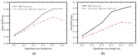
Figure 12.
RMS of the pitch and heave motions at different sea states. (a) Heave; (b) Pitch.
A slight deviation from this trend is observed at Hs = 0.5 m, where the reduction ratios for both motions exhibit a minor decrease. Although this non-monotonic behavior warrants further investigation, it may be preliminarily attributed to the wave encounter frequency approaching a resonant mode of the vessel or a slight sub-optimality in the controller tuning under this specific sea state, suggesting an opportunity for future refinement.
5.3. Sensitivity Analysis to Additive Noise
To evaluate the robustness of the proposed controller against practical sensor inaccuracies, a comprehensive sensitivity analysis was conducted by introducing additive white Gaussian noise to the measured states. The noise variance, , was tested at two representative levels: 0.05 and 0.1, under moderate (0.3 m) and severe (0.6 m) sea states.
The performance impact is quantified by the change in reduction ratio relative to the baseline PID controller, as detailed in Table 3 and Figure 13. A negative value indicates performance degradation compared to the baseline PID, while the magnitude reflects the sensitivity degree.
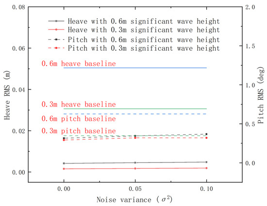
Figure 13.
Sensitivity of motion RMS to additive sensor noise.
As expected, the control performance exhibits a declining trend with increasing noise variance across both sea states in Table 4. For instance, under the 0.3 m sea state, the pitch angle reduction ratio decreases from its nominal value (presumably ~35.55% from Table 2) to −12.20% at and further to −7.86% at . This indicates that higher sensor noise levels challenge the ESO’s estimation accuracy and consequently the controller’s effectiveness.

Table 4.
Reduction ratios of motion RMS under different noise variances.
The pitch motion control demonstrates greater sensitivity to noise compared to heave motion. Under the 0.3 m sea state, the performance degradation for heave is −94.71% and −94.08% for and 0.1, respectively, which is significantly less than the attenuation observed in roll motion under identical conditions. This can be attributed to the inherently different dynamics and observability characteristics of heave versus pitch motions, with pitch motion likely being more susceptible to high-frequency noise due to its direct excitation by wave forces.
Despite the performance degradation, it is crucial to note that the proposed controller maintained motion reduction capability (absolute root mean square value below PID reference value). This demonstrates the ESO’s role as an effective filter. The ESO inherently attenuates high-frequency measurement noise while faithfully estimating the low-frequency lumped disturbances (wave forces and model uncertainties), thereby preventing the noise from causing severe instability or high-frequency chattering in the control actions.
In conclusion, the simulation results confirm the multi-faceted advantages of the proposed controller, including substantial motion reduction, improved phase response, and consistent performance across varying sea conditions. These improvements are fundamentally driven by the synergistic combination of the backstepping control law and the ESO’s disturbance estimation capabilities.
6. Conclusions
This study has developed and numerically validated a novel ESO-based backstepping control strategy for vertical motion stabilization of high-speed multihulls in irregular seas. The core of the approach lies in its explicit handling of wave-induced disturbances as stochastic processes and the decoupled estimation–compensation structure via the Extended State Observer. The simulation results under varying sea states (significant wave height from 0.1 m to 0.6 m) lead to the following principal conclusions:
- (1)
- The proposed controller demonstrates consistent and significant superiority over a conventional PID baseline. It achieves an average reduction of 18.7% in the RMS of heave displacement and 37.5% in the RMS of pitch angle across all tested sea states. This performance translates directly to improved passenger comfort, reduced crew fatigue, and diminished structural loads.
- (2)
- A key strength of the controller is its ability to maintain, and even improve, its efficacy as wave energy increases. The reduction ratios for both heave and pitch generally exhibit a positive correlation with significant wave height, underscoring the robustness of the ESO in adapting to and compensating for disturbances of growing magnitude.
- (3)
- Beyond RMS reduction, the controller yields a markedly improved dynamic response. It features shorter settling times and significantly lower transient overshoots compared with PID control. Furthermore, the phase analysis indicates a reduction in phase lag, allowing the vessel to realign more rapidly with wave excitation, which is crucial for mitigating wave-impact loads.
- (4)
- The sensitivity analysis confirms that while performance degrades under additive sensor noise, the controller maintains its fundamental stabilizing capability. The ESO acts as an effective filter, attenuating high-frequency noise while estimating low-frequency disturbances, thereby preventing severe instability or control chattering.
In summary, the simulation results strongly confirm the high effectiveness and promise of the proposed control framework for application on high-speed multihulls operating in moderate-to-rough seas. The study also acknowledges its limitations, primarily rooted in the simulation-based validation using a simplified hydrodynamic model. Therefore, the following steps are identified as critical for advancing this research towards practical implementation:
- -
- Conducting wave basin model-scale tests or full-scale sea trials is essential to confirm performance under real-world conditions, including complex wave directions, wind, and currents.
- -
- A systematic performance comparison with other modern advanced control methods (e.g., Adaptive Sliding Mode Control, Nonlinear Model Predictive Control) is necessary to definitively position its relative advantages.
- -
- Future work should thoroughly investigate the controller’s performance under sensor faults, actuator saturation, and significant model mismatches to assess its fault tolerance and operational reliability.
- -
- Frequency-domain analysis, such as Power Spectral Density (PSD) comparisons and testing under regular wave excitations, will provide further insights into the controller’s performance across the frequency spectrum and facilitate direct benchmarking for engineering design.
Author Contributions
Conceptualization, X.F.; methodology, X.F. and Z.L.; software, G.L.; validation, X.F. and G.L.; formal analysis, X.F.; investigation, T.N. and F.J.; resources, F.J.; data curation, T.N. and F.J.; writing—original draft preparation, H.L. and X.F.; writing—review and editing, H.L. and T.N.; visualization, H.L. and X.F.; supervision, Z.L., F.J. and J.Z.; project administration, Z.L. and F.J.; funding acquisition, F.J. and J.Z. All authors have read and agreed to the published version of the manuscript.
Funding
This research was supported by the National Natural Science Foundation of China (Grant No: 52401419), the Young Elite Scientists Sponsorship Program by CAST (Grant No: YESS20220013), and the Natural Science Foundation of Heilongjiang Province, China (Grant No: LH2021E038).
Data Availability Statement
The original contributions presented in this study are included in the article. Further inquiries can be directed to the corresponding author.
Conflicts of Interest
Xianjin Fang was employed by Guangzhou Marine Engineering Corporation. Guosheng Li was employed by CNGC East China Institute of Photo-Electron IC. The remaining authors declare that the research was conducted in the absence of any commercial or financial relationships that could be construed as a potential conflict of interest.
Appendix A. Theoretical Preliminaries
In order to derive the control law, several theoretical preliminaries should be presented.
Definition A1.
Consider the nonlinear stochastic system [19]:
Definition A2.
Consider the nonlinear stochastic system (A1) and let be a function of , where denotes the set of functions with continuous second partial derivatives. Based on Ito’s formula, the stochastic differentiation of is given as follows:
where is the trace operator.
Along with the nonlinear stochastic system (A1), the infinitesimal generator of a function is defined as
Definition A3.
Considering the nonlinear stochastic system (A1): (1) The equilibrium is globally stable in probability if there exists a function for all such that , . (2) The equilibrium is globally asymptotically stable in probability if there exists a function for all such that , .
Definition A4.
The projection algorithm is formulated as follows [17]:
where and . and denote an arbitrarily small constant. Based on the defined projection algorithm, if there exists with a symmetric positive definite matrix and , the following conditions can be satisfied as follows:
- (1)
- ;
- (2)
- is continuous and satisfies ;
- (3)
- with .
Theorem A1.
Assuming that for and non-negative definite matrices , there exist a function , two functions and , a positive constant , and a Borel-measurable and strictly increasing function , such that , and
Then, there exists a unique strong solution for the stochastic system (A1) satisfying .
Theorem A2.
Assuming that there exist a function , two functions , , and a continuous and nonnegative function , such that , and
Then, there exists a unique strong solution for the stochastic system (A1), and the system equilibrium point is globally stable satisfying ,.
Appendix B. Numerical Results of Observer Gain vs. Actuator Response
Table A1 summarizes the actuator deflection characteristics and system performance under three sets of observer gain combinations, explicitly illustrating the relationship between gain magnitude and saturation behavior:

Table A1.
Actuator deflection and saturation status under different observer gain combinations.
Table A1.
Actuator deflection and saturation status under different observer gain combinations.
| Observer Gain Combination () | Maximum Deflection of T-Foil | Maximum Deflection of Flap | Actuator Status | RMS Increase in Heave/Pitch Motion (vs. Recommended Gain) |
|---|---|---|---|---|
| (5, 6) [Recommended Gain] | +5.2° (0.0908 rad) | −6.8° (−0.1187 rad) | Unsaturated | 0% (baseline) |
| (8, 9) [Higher Gain] | +7.9° (0.1379 rad) | −9.5° (−0.1658 rad) | Near-Saturation | Heave: +3.5%; Pitch: +4.2% |
| (10, 12) [Excessively High Gain] | +9.3° (0.1623 rad) | −11.2° (−0.1955 rad) | Saturated | Heave: +8.7%; Pitch: +11.2% |
Recommended Gain Regime (): The maximum deflection of both actuators is well within their physical limits. This gain configuration balances disturbance estimation accuracy (estimation error: 5.2%) and actuator feasibility, serving as the optimal parameter set for subsequent simulations.
Near-Saturation Regime (): The T-foil deflection approaches its upper limit (+7.9° vs. maximum +8°), and the flap deflection is close to its lower limit (−9.5° vs. maximum −10°). Although no explicit saturation occurs, the margin for dynamic adjustment is narrowed, leading to a slight degradation in motion suppression performance.
Saturation Regime (): The T-foil deflection exceeds its upper limit by 1.3° (+9.3° > +8°), and the flap deflection exceeds its lower limit by 1.2° (−11.2° < −10°). Despite a marginal improvement in disturbance estimation accuracy (estimation error: 3.8%), the saturated actuators fail to generate the theoretical control force/moment. Consequently, the RMS values of heave and pitch motions increase significantly by 8.7% and 11.2%, respectively, confirming that excessively high gains undermine system performance.
References
- Fossen, T.I. Handbook of Marine Craft Hydrodynamics and Motion Control; John Wiley & Sons: Hoboken, NJ, USA, 2011. [Google Scholar]
- Li, W.; Zhang, J.; Xu, W. High-Speed Multihull Anti-Pitching Control Based on Heave Velocity and Pitch Angular Velocity Estimation. ISA Trans. 2024, 146, 380–391. [Google Scholar] [CrossRef] [PubMed]
- Yin, S.; Rodriguez-Andina, J.J.; Jiang, Y. Real-Time Monitoring and Control of Industrial Cyberphysical Systems: With Integrated Plant-Wide Monitoring and Control Framework. IEEE Ind. Electron. Mag. 2019, 13, 38–47. [Google Scholar] [CrossRef]
- Zhang, J.; Sun, T.; Liu, Z. Robust Model Predictive Control for Path-Following of Underactuated Surface Vessels with Roll Constraints. Ocean Eng. 2017, 143, 125–132. [Google Scholar] [CrossRef]
- Li, G.; Liu, Z.; Zhang, J.; Zheng, L. Robust Predictive Control for Anti-Rolling Path Following of Underactuated Surface Vessels Using Adaptive Kalman Filter. Int. J. Adv. Robot. Syst. 2019, 16, 1729881419877269. [Google Scholar] [CrossRef]
- De la Cruz, J.; Aranda, J.; Giron-Sierra, J.; Velasco, F.; Esteban, S.; Diaz, J.; de Andres-Toro, B. Improving the Comfort of a Fast Ferry. IEEE Control Syst. 2004, 24, 47–60. [Google Scholar] [CrossRef]
- Lopez, R.; Santos, M.; Polo, O.; Esteban, S. Experimenting a Fuzzy Controller on a Fast Ferry. In Proceedings of the International Conference on Control Applications, Glasgow, UK, 18–20 September 2002; Volume 2, pp. 1082–1087. [Google Scholar] [CrossRef]
- Aranda, J.; De La Cruz, J.M.; Díaz, J.M. Design of a Multivariable Robust Controller to Decrease the Motion Sickness Incidence in Fast Ferries. Control Eng. Pract. 2005, 13, 985–999. [Google Scholar] [CrossRef]
- AlaviMehr, J.; Lavroff, J.; Davis, M.R.; Holloway, D.S.; Thomas, G.A. An experimental investigation of ride control algorithms for high-speed catamarans part 2: Mitigation of wave impact loads. J. Ship Res. 2017, 61, 51–63. [Google Scholar] [CrossRef]
- Javanmard, E.; Mehr, J.A.; Ali-Lavroff, J.; Holloway, D.S.; Davis, M.R. An experimental investigation of the effect of ride control systems on the motions response of high-speed catamarans in irregular waves. Ocean Eng. 2023, 281, 114899. [Google Scholar] [CrossRef]
- AlaviMehr, J.; Lavroff, J.; Davis, M.R.; Holloway, D.S.; Thomas, G.A. An experimental investigation on slamming kinematics, impulse and energy transfer for high-speed catamarans equipped with ride control systems. Ocean Eng. 2019, 178, 410–422. [Google Scholar] [CrossRef]
- Tavakoli, S.; Dashtimanesh, A.; Mancini, S.; Mehr, J.A.; Milanesi, S. Effects of vertical motions on roll of planing hulls. J. Offshore Mech. Arct. Eng. 2021, 143, 041401. [Google Scholar] [CrossRef]
- Li, A.; Li, Y. Numerical and Experimental Study on Seakeeping Performance of a High-Speed Trimaran with T-Foil in Head Waves. Pol. Marit. Res. 2019, 26, 65–77. [Google Scholar] [CrossRef]
- Majidiyan, H.; Enshaei, H.; Howe, D. A Concise Account for Challenges of Machine Learning in Seakeeping. Procedia Comput. Sci. 2025, 253, 2849–2858. [Google Scholar] [CrossRef]
- Peng, Y.; Ming, Y.; Zhang, J.; Liu, Z.; Li, G. A Robust Finite Time-Based Anti-Pitching Control Method for a High-Speed Multihull. In Proceeding of the 2020 39th Chinese Control Conference (CCC), Shenyang, China, 27–30 July 2020; pp. 3293–3298. [Google Scholar]
- Raman-Nair, W.; Chin, S.N. Simulation of Flexural Dynamics of a Slender Ship Undergoing Heave and Pitch. Acta Mech. 2021, 232, 2443–2453. [Google Scholar] [CrossRef]
- Do, K.D. Control of Fully Actuated Ocean Vehicles under Stochastic Environmental Loads in Three Dimensional Space. Ocean Eng. 2015, 99, 34–43. [Google Scholar] [CrossRef]
- Huang, L.; Han, Y.; Duan, W.; Chen, Y.; Ma, S. Numerical and Experimental Studies on a Predictive Control Approach for Pitch Stabilization in Heading Waves. Ocean Eng. 2018, 169, 388–400. [Google Scholar] [CrossRef]
- Yu, X.; Xie, X.-J.; Duan, N. Small-Gain Control Method for Stochastic Nonlinear Systems with Stochastic iISS Inverse Dynamics. Automatica 2010, 46, 1790–1798. [Google Scholar] [CrossRef]
Disclaimer/Publisher’s Note: The statements, opinions and data contained in all publications are solely those of the individual author(s) and contributor(s) and not of MDPI and/or the editor(s). MDPI and/or the editor(s) disclaim responsibility for any injury to people or property resulting from any ideas, methods, instructions or products referred to in the content. |
© 2025 by the authors. Licensee MDPI, Basel, Switzerland. This article is an open access article distributed under the terms and conditions of the Creative Commons Attribution (CC BY) license (https://creativecommons.org/licenses/by/4.0/).