Article

Unsteady Hydrodynamic Analysis and Experimental Methodology for Voith Schneider Propeller

1
College of Ship and Ocean, Naval University of Engineering, Wuhan 430033, China
2
College of Shipbuilding Engineering, Harbin Engineering University, Harbin 150001, China
*
Author to whom correspondence should be addressed.
J. Mar. Sci. Eng. 2025, 13(10), 1933; https://doi.org/10.3390/jmse13101933
Submission received: 22 August 2025 / Revised: 3 October 2025 / Accepted: 6 October 2025 / Published: 9 October 2025
(This article belongs to the Section Ocean Engineering)

Abstract

The Voith Schneider Propeller (VSP) operates with blades undergoing an approximately sinusoidal periodic motion along a circular path. Hydrodynamically, the continuous significant variation in the angle of attack between the blades and incoming flow, together with additional inertial effects caused by accelerated rotation, complicates the computation and measurement of hydrodynamic performance. To investigate the unsteady hydrodynamic behavior resulting from this coupled motion, a numerical model incorporating adaptive mesh refinement was developed to simulate VSP performance. Based on insights into the interaction between blade motion and hydrodynamics, an experimental platform was designed using servo motors to achieve precise synchronized blade control, enabling mutual validation between numerical simulations and transient hydrodynamic measurements. Results demonstrate that the coupled blade motion induces nonlinear variations in hydrodynamic forces. Rotational power loss limits VSP efficiency, and a negative thrust regime occurs at high advance coefficients. Rapid blade flipping leads to flow separation, identified as the primary cause of nonlinear lateral forces. The consistency between numerical and experimental results provides reliable data supporting theoretical studies. These findings offer valuable insights for optimizing motion control strategies in cycloidal propeller applications.

1. Introduction

The Voith Schneider Propeller (VSP) is a specialized marine propulsion system that generates vectored thrust in any horizontal direction through vertically mounted blades attached to a rotating disk. The blades are uniformly distributed along the disk’s circumference, with each blade undergoing uniform revolution around the disk while simultaneously rotating about its own axis at variable speeds [1]. By altering the deflection angle of blade rotation, VSP changes the angle of attack between the blades and the resultant inflow during motion, thereby generating planar vector thrust. This allows the modulation of thrust magnitude and direction while providing primary propulsion for vessels [2]. Consequently, vessels equipped with VSP maintain excellent maneuverability during mooring or at low speeds, and demonstrate superior control capabilities compared to screw propellers in dynamic positioning applications [3].
VSP was improved by Schneider [4] based on Kirsten [5] and successfully commercialized [6]. Combining the revolution of VSP blades with the vessel’s forward motion, the trajectory of a single blade forms a cycloid. Thus, VSP can be classified as a variable low-pitch cycloidal propeller. In current research nomenclature, “cycloidal propeller” encompasses most studies focusing on different “cycloidal” blade motion strategies featuring straight blades as the primary characteristic. Initial research on cycloidal propellers primarily employed simplified models to estimate time-averaged hydrodynamic performance. W. Just [7] segmented cycloidal propeller blades spanwise into multiple micro-elements based on airfoil theory, calculating hydrodynamic characteristics of each micro-element using two-dimensional wing theory, achieving the earliest theoretical method for hydrodynamic performance calculation of cycloidal propellers. Although the calculated results aligned with hydrodynamic parameter trends from Voith’s (Voith GmbH., Heidenheim, Germany) experimental data, the model’s applicability remained limited. To date, following airfoil theory and other approaches, numerous scholars have proposed various theoretical methods for hydrodynamic performance prediction of cycloidal propellers, including representative approaches such as the lifting-line theory by Isay [8], momentum theory by Taniguchi [9,10,11], and vortex theory by M.R. Mendenhall and S.B. Spangler [12].
Recent research on theoretical models has adopted more sophisticated methods to describe and predict unsteady flow and hydrodynamic performance. Prabhu et al. [13,14] employed the panel method to discretize blade surfaces into straight panels, distributing sources and vortices as singularities on each panel. By solving potential flow equations, the velocity potential and pressure distribution across the flow field were computed, effectively capturing the unsteady flow field and hydrodynamic characteristics of cycloidal propellers. Halder et al. [15] comprehensively considered physical phenomena including dynamic virtual camber effects, near-wake and shed-wake interactions, and leading-edge vortices. This study integrated a nonlinear lifting-line model with the Polhamus leading-edge suction analogy, Theodorsen’s method, and a modified double-multiple streamtube model to establish a low-order unsteady hydrodynamic model, which was validated against time-history data from single-blade hydrodynamic measurements at low Reynolds numbers. Epps et al. [16] developed a low-order computational model based on the vortex-lattice method, enhancing viscous flow prediction through viscous-thickness and load coupling techniques. Wake stability was optimized using the Panel-Averaged Wake-Induced Velocity method, achieving model accuracy meeting preliminary design requirements.
Synthesizing the aforementioned theoretical model research, calculation methods based on theoretical models typically neglect three-dimensional flow effects or viscous effects in their assumptions, requiring experimental data for model coefficient corrections. Their reliance on empirical formulas for unsteady flow phenomena such as turbulence and dynamic stall results in limited computational accuracy for complex geometries and unsteady flow fields. With advancements in viscous Computational Fluid Dynamics (CFD) numerical simulation methods based on solving Navier–Stokes equations [2], CFD approaches demonstrate advantages in capturing high-precision flow details, adapting to complex geometries, and coupling multiphysics. Consequently, in recent years, numerous scholars have employed CFD methods to investigate the influence of various parameters on the hydrodynamic performance of cycloidal propellers.
Hu et al. [17,18] systematically analyzed the vortex structure evolution of cycloidal propellers under blade rotational motion. The study revealed that sudden changes in blade rotational speed trigger boundary layer separation, forming a dual “suction vortex-lift vortex” structure that induces periodic load fluctuations. The influence of parameters such as eccentricity and blade rotation center position on vortex structures was further summarized. Yan et al. [19] established kinematic models for cycloidal propellers using planar linkage mechanisms—specifically four-bar and mixed four-bar/five-bar mechanisms. Research demonstrated that blade rotation angle and angular velocity range are core factors affecting hydrodynamic performance, as control mechanism parameters alter blade motion laws and thereby impact propulsion effectiveness. Hu et al. [20] developed a two-dimensional numerical model for cycloidal propellers. Results indicate that adjusting eccentricity optimizes the matching between thrust and advance coefficient, enhances efficiency, reduces blade interference, and reveals that azimuthal angle variations under high advance coefficients intensify turbulent fluctuations and increase side thrust. Liu et al. [21] investigated directional thrust stability of cycloidal propellers under VSP and Cyclorotor motion modes. Findings show the Cyclorotor mode—where blade deflection angles follow a near-sinusoidal variation—exhibits smaller side thrust fluctuations and a more concentrated spatiotemporal distribution of total thrust.
In the development of theoretical models and CFD methods, the correction of theoretical model parameters based on experimental data and the validation of numerical calculation accuracy are indispensable. Early cycloidal propellers were primarily driven by mechanical structures (connecting rods, cranks, camshafts, gears, etc.) [22]. Given the fixed mechanical design, blade motion patterns were highly standardized. With advancements in high-performance electric motor development and control technology upgrades, the model testing methods for cycloidal propellers have progressively evolved.
Fasse et al. [23] independently controlled the pitch motion of each blade using servo motors, conducting systematic experiments on sinusoidal pitch control of cycloidal propellers. The study revealed the hydrodynamic center offset characteristics of cycloidal propellers and validated the necessity of asymmetric pitch control. Halder et al. [15] measured transient hydrodynamic time-history data of a single-blade cycloidal propeller under different advance coefficients in a water tunnel. The study discovered that during blade reversal, flow separation causes a sudden change in the angle of attack and generates negative side thrust. Additionally, negative virtual camber during the first half of the blade motion cycle reduces both thrust and side thrust, while positive virtual camber in the latter half enhances thrust, resulting in thrust asymmetry phenomena.
Research synthesizing the above findings reveals that during the complex coupled motion of cycloidal propeller blades, blade-water interactions coexist with blade-blade interactions. Additionally, dynamic stall phenomena accompany large-angle-of-attack conditions. Under the combined influence of these factors, a highly unsteady complex flow field forms in cycloidal propellers, which features multi-scale vortex generation, evolution, and dissipation. Consequently, hydrodynamic forces on blades exhibit unsteady characteristics. Therefore, whether employing theoretically modeled assumptions, CFD methods incorporating turbulence equations, or experimentally testing cycloidal propellers via complex mechanical-structure designs and high-performance electric motors, accurately calculating and measuring unsteady hydrodynamic performance and flow fields remains a significant challenge. In summary, this study focuses on the transient hydrodynamic characteristics during the coupled motion of VSP blades. A numerical method for predicting VSP unsteady hydrodynamics was established based on publicly available experimental data. Furthermore, breaking through the limitations of traditional mechanical structures, a servo motor-controlled VSP device was designed to achieve precise blade rotation control under high eccentricity conditions. The variation patterns of unsteady transient hydrodynamics with eccentricity were thoroughly analyzed, providing solid experimental support for theoretical investigations.
Building upon the aforementioned research landscape, this paper focuses on VSP as a practical application of cycloidal propellers, investigating numerical calculation and experimental measurement methods for unsteady transient hydrodynamics induced by blade-coupled motion. Section 2.1 analyzes the coupled motion of uniform blade revolution and variable-speed blade rotation, deriving kinematic equations for VSP blades. Section 2.2 discusses and verifies the computational method for VSP unsteady hydrodynamics, enhancing numerical accuracy through vortex-region identification using the Omega vortex criterion and adaptive mesh refinement. Section 3.1 examines variation patterns of blade unsteady transient hydrodynamics with eccentricity based on VSP blade-coupling kinematics. Section 3.2 introduces a planar vector thrust measurement test platform for VSP. Utilizing a towing tank platform, calibration of horizontal static balance and blade-disk dynamic balance was completed. By comparing transient experimental measurements with numerical simulations under varying eccentricity conditions and analyzing flow field characteristics during blade-coupled motion, this study evaluates the feasibility of servo-motor-based synchronized motion control, planar vector thrust measurement, and numerical methods. Finally, unsteady hydrodynamic characteristics of VSP under different eccentricities and advance coefficients are systematically summarized.

2. Principles and Methods

2.1. Analysis of Coupled Blade Motion in VSP

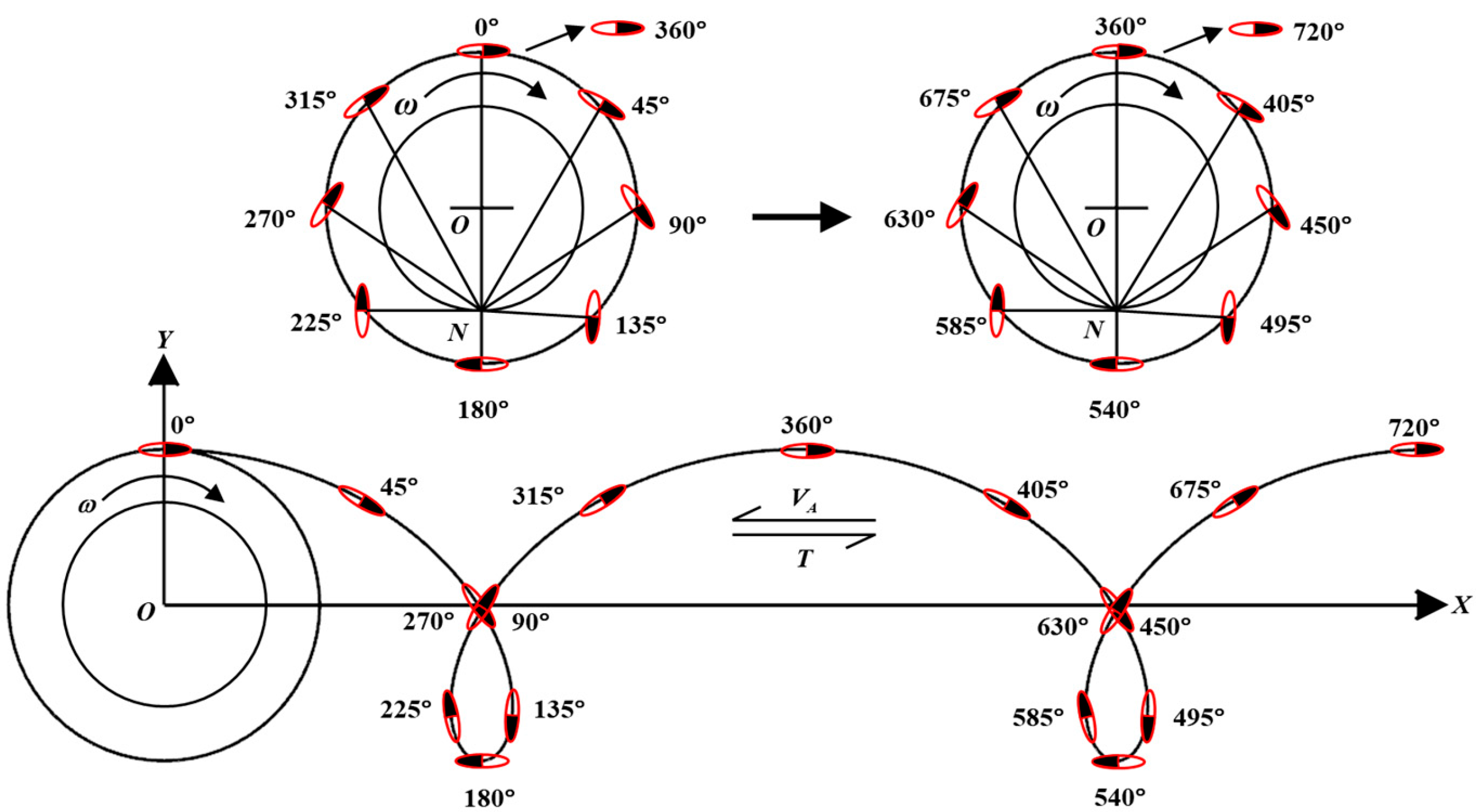
As a representative type of variable low-pitch cycloidal propeller, the VSP blades’ coupled motion can be decomposed into variable-speed rotation about their own axes while simultaneously undergoing uniform revolution around the disk axis. This unique coupled blade motion follows the “Normal Intersection Law” [24], wherein within the blade profile plane, the blade chord always remains perpendicular to the line connecting the blade center and point N, as shown in Figure 1.
In Figure 1, point N is termed the eccentricity control point. The distance from point N to the VSP disk center O defines the eccentric distance ON ¯ . Within one operational cycle, the lift and drag generated by blades are decomposed into the propulsion direction and transverse direction. Their superposition yields thrust T and side thrust T S . Non-dimensionalization produces thrust coefficient K T and side thrust coefficient K Ts . The advance coefficient J is defined based on the advance speed and rotational speed.
K T = T ρ n g 2 D 3 L
K T s = T s ρ n g 2 D 3 L
J = V A n g D
In the equations, ρ denotes fluid density, L represents blade span length, n g signifies rotational speed, and D stands for propeller diameter. When the position of eccentricity control point N changes, the blade angle about its rotation axis—governed by the Normal Intersection Law—simultaneously varies. Consequently, modifying the angle-of-attack variation pattern between blades and the resultant inflow generates thrust along the inflow direction and side thrust perpendicular to it, enabling independent regulation of both magnitude and direction of the propeller’s resultant force independent of rotational speed.
As derived above, the eccentricity control point of VSP constitutes the core physical quantity determining thrust magnitude and direction. Its position is defined with reference to a polar coordinate system. The ratio of eccentric distance ON ¯ to the rotation radius r, denoted as e   =   ON ¯ / r , is termed the eccentricity or pitch [25]. The angle of the eccentricity control point about the revolution axis is defined as the azimuthal angle ψ . The angle β between the blade chord and the disk tangent represents the blade rotation deflection angle, with ψ positive clockwise and β positive counterclockwise. When a VSP blade completes one full revolution cycle around the disk, its rotation motion simultaneously completes one cycle. Thus, the revolution and rotation motion periods are equal in VSP coupled kinematics. By applying the sine theorem, the functional relationships of blade rotation deflection angle β and rotation angular velocity ω c with revolution angle are derived:
β ( θ ) = arcsin e sin ( θ ψ ) 1 + 2 e cos ( θ ψ ) + e 2
ω c ( θ ) = d β d t = ω e 2 + e cos ( θ ψ ) 1 + 2 e cos ( θ ψ ) + e 2
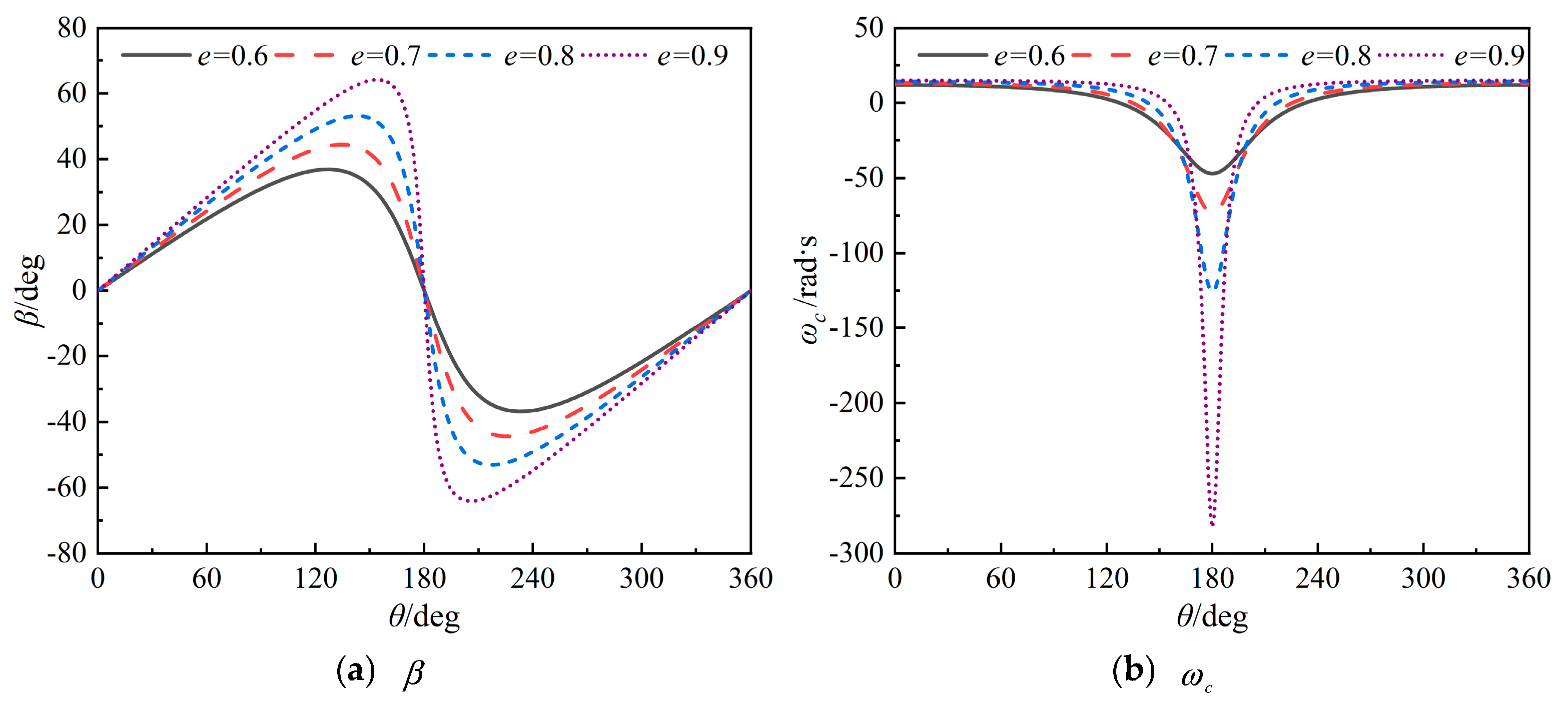
The blade distribution position shown in Figure 1 is set as the initial state for numerical simulation. The azimuthal angle ψ of the control point in the figure is defined as 0°. According to Equations (4) and (5), when the revolution speed ng is 300 r/min, the blade rotation deflection angle β and blade rotation angular velocity ω c at eccentricities e = 0.6–0.9 vary with the revolution angle, as shown in Figure 2a,b.
Figure 2a illustrates that blade rotation deflection angle follows an approximately sinusoidal variation with revolution angle. During coupled revolution and rotation motion, symmetry exists between the first half-cycle (revolution angle 0° to 180°) and second half-cycle (revolution angle 180° to 360°), with the symmetry axis at the 180° revolution position. Specifically, blade rotation deflection angles exhibit equal magnitude but opposite directions at symmetric positions during these half-cycles. Considering the coupled blade motion trajectory in Figure 1, the continuously varying blade rotation speed causes non-uniformity in both the angle of attack between blades and resultant inflow, and the resultant velocity magnitude distribution along the chord. Simultaneously, given VSP blades’ perpendicular orientation to incoming flow, blades in the second half-cycle experience wake influences from the first half-cycle. Consequently, flow conditions differ significantly between port and starboard sides along the advance direction. This flow asymmetry substantially complicates VSP hydrodynamic variations.
Analysis of the curves in Figure 2b depicting blade rotation angle and angular velocity versus revolution angle reveals that under constant revolution speed, both the amplitude of blade rotation angle and rotation angular velocity increase with rising eccentricity. Under high-eccentricity conditions, the rotation angular velocity significantly exceeds revolution speed, causing power consumption for driving blade rotation to escalate dramatically. Therefore, calculation of VSP open-water efficiency must account for power dissipation due to rotational torque [26,27]. By separately calculating thrust torque from revolution and rotational torque, the open-water efficiency formula for VSP is derived as Equation (6).
η = T V A 2 π n g Q g + 2 π n b Q b
In the equations, n g and n b denote revolution speed and rotation speed, respectively, while Q g and Q b represent revolution torque and rotation torque. For efficiency calculation within one motion cycle of the cycloidal propeller, due to the continuous variation in rotation speed, the rotation torque and revolution torque are superimposed as follows:
Q = Q g + n b n g Q b
After non-dimensionalization, the torque coefficients for revolution and rotation and the open-water efficiency calculation formula are derived:
K Q = Q ρ n g 2 D 4 L
η = T a v g V A 2 π n g Q a v g
Notably, as eccentricity increases, the maximum blade rotation angular velocity at the 180° revolution position exhibits a nonlinear growth trend. Particularly given the high aspect ratio and small stall angle of cycloidal propeller blades, the angle of attack at certain positions transiently exceeds the stall angle, which degrades VSP hydrodynamic performance. Simultaneously, continuous large-scale variations in blade-inflow angle of attack and additional inertial forces induced by accelerating rotation create complex hydrodynamic calculation and measurement challenges. Especially under an e = 0.9 eccentricity, maximum rotation angular velocity approaches 10 times the revolution angular velocity. This rapid rotation velocity fluctuation generates reciprocating loads on the propulsion system per motion cycle. As revolution speed increases, high-frequency impacts compromise the structural longevity and intensify VSP hydrodynamic fluctuations. Therefore, based on the above analysis of blade coupled motion, it is imperative to employ numerical simulation to further investigate the variation patterns of unsteady hydrodynamic performance during cyclic blade motion.

2.2. Validation of VSP Hydrodynamic Numerical Calculation Method

In the coupled motion of VSP combining directional revolution and variable-speed rotation, blade kinematics exhibit an approximate sinusoidal periodic oscillation along the circumference. Hydrodynamically, continuous variations in magnitude and direction of both blades and resultant inflow velocity produce time-dependent hydrodynamic forces, resulting in a non-steady flow state. Consequently, analyzing blade coupled motion and computing complex hydrodynamics constitute the foundation for investigating VSP unsteady hydrodynamic performance.

2.2.1. Computational Model and Domain Division

In 1969, Ficken and Dickerson [28] conducted hydrodynamic performance tests on a 9-inch scaled VSP model under varying eccentricities (e = 0.4~0.9), azimuthal angles (−90°~+90°), and blade counts (6, 3, and 2 blades). This dataset remains the most comprehensive and frequently cited experimental data source in open literature, serving as the validated reference for VSP experimental data. This paper adopts this test model for numerical simulation validation. During the tests, the blade rotation axis was positioned at 50% chord length from the leading edge, with blade parameters listed in Table 1.
The difficulty in VSP hydrodynamic performance calculation lies in accurately simulating the coupled motion of multiple blades. Therefore, sliding meshes are employed to simulate the relative rotational motion between different regions in the flow field. According to the motion characteristics of VSP, the computational flow field is divided into three domains: a uniformly rotating revolution domain, a variably rotating rotation domain, and a continuous enclosed stationary domain containing the propeller. The bottom and side boundaries of the computational domain are modeled as no-slip walls, directly representing the physical walls of the towing tank used in the experiments. The blade model and detailed division of the computational domain are shown in Figure 3.
Interfaces dynamically updated with mesh movement are established between domains for data exchange, accurately replicating blade-fluid interactions in numerical simulations. Within StarCCM+, blade motion equations are embedded via User Define Function (UDF) modules to simulate coupled multi-blade kinematics of cycloidal propellers. For all operating conditions, the blade motion was calculated over eight full revolution cycles to ensure computational convergence. The test report describes a Reynolds number range of 1.3   ×   10 5 to 2.1   ×   10 5 . Computations employ an Implicit Unsteady physical model, with VSP revolution speed n g set at 300 r/min. Based on revolution speed, a time-step resolution of 1° per revolution step is implemented, corresponding to a time step of 5.556   ×   10 4 s.

2.2.2. Governing Equations

In numerical simulations, the fluid is treated as a viscous incompressible flow. The governing equations include the continuity equation and the momentum conservation equation [29]. Considering the turbulence characteristics of VSP rotating in viscous incompressible flow, the Reynolds-averaged approach is employed to derive the Reynolds Average Navier–Stokes (RANS) equations. The fluid continuity and momentum equations are expressed as Equations (10) and (11).
u i x i = 0
t ( ρ u i ) + x j ( ρ u i u j ) = p x i + x j ( μ u i x j ρ u i u j ¯ ) + f i
where u i and u j represent the time-averaged velocity components, t represents time, p represents the time-averaged fluid pressure, x i and x j represent the displacement components, μ represents the dynamic viscosity coefficient, f i represents the gravitational force per unit mass acting on the fluid, and ρ u i u j ¯ represents the Reynolds stress term. However, due to the unknown nature of the time-averaging process, introducing a turbulence model to close the system of equations is necessary.
Turbulence models serve as approximate representations of actual turbulent phenomena. Therefore, turbulence model selection must consider the real fluid flow state and target solution types. The SST k-ω turbulence model is selected to close the RANS equations in numerical simulations, which is a model extensively applied and validated in propeller hydrodynamic computations [17,30].

2.2.3. Mesh Size Uncertainty Verification

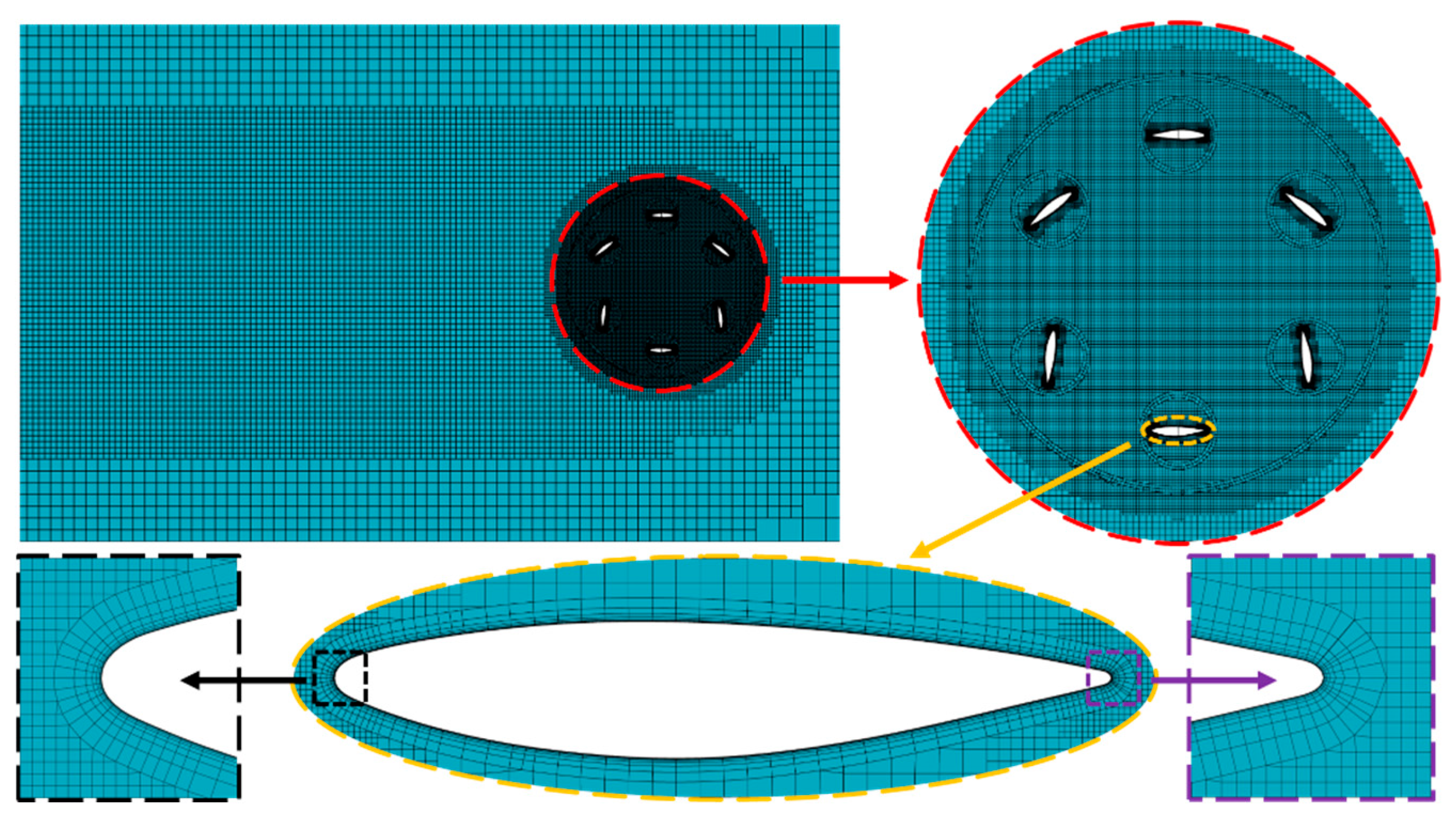
The unsteady flow field induced by VSP coupled motion and mutual blade interference complicates hydrodynamic computation. Considering the interaction between turbulence models and mesh convergence, different turbulence models exhibit distinct mesh convergence behaviors. Following the International Towing Tank Conference (ITTC) recommendations, five mesh sets are generated for mesh size uncertainty verification while satisfying wall mesh size requirements for the selected SST k-ω turbulence model. The mesh refinement ratio in three directions is r m   =   2 , with the first wall-bounded cell height satisfying y+ < 1 [31]. Given the vertical blade configuration, the propeller wake region undergoes mesh refinement. The reference mesh configuration is shown in Figure 4.
This paper conducts mesh size uncertainty verification under maximum efficiency conditions at eccentricities of e = 0.6, 0.7, and 0.8. Thrust coefficient results for different mesh densities are presented in Table 2, Table 3 and Table 4.
Analysis of thrust coefficient results across different Mesh densities reveals that, due to measurement errors in experimental data and computational challenges in precisely capturing dynamic stall effects induced by abrupt blade rotation velocity changes at high eccentricities, numerical results exhibit increasing deviations from experimental data as eccentricity rises. Nevertheless, for medium-Mesh and finer resolutions, the thrust coefficient error does not exceed 5.696%.
Based on the aforementioned results, Mesh uncertainty verification of numerical calculations is performed using the Correction Factor Method according to ITTC guidelines. This method is widely applied in uncertainty verification [32], with specific details referenced in Wilson and Stern [33] and Roache [34]. The uncertainty calculation process is not reiterated here. Mesh uncertainty verification results using the ITTC Correction Factor Method are presented in Table 5. For all five Mesh sets, the thrust coefficient uncertainty is less than 1%, falling within acceptable limits. Considering computational resources and error control, the Medium Mesh is selected for subsequent calculations.

2.2.4. Adaptive Mesh Refinement

Under high-eccentricity conditions of the VSP, blades undergo rapid flipping motions near the eccentric points. This continuous large-scale variation in blade-inflow angle of attack intensifies the nonlinear pulsation characteristics of VSP hydrodynamics. Consequently, for accurate prediction of VSP hydrodynamic performance, simulating the unsteady flow field under mutual blade interference is particularly crucial. Adaptive Mesh Refinement (AMR) dynamically refines or coarsens mesh cells during the fluid solution based on adaptive criteria, automatically interpolating solved physical quantities onto the adapted mesh. This technique optimally distributes the mesh within computational domains, effectively enhancing the mesh’s capability to capture targeted fluid features [35]. AMR employs midpoint subdivision for mesh refinement, where one refinement cycle produces a mesh count equivalent to the node count of the base mesh, as illustrated in Figure 5.
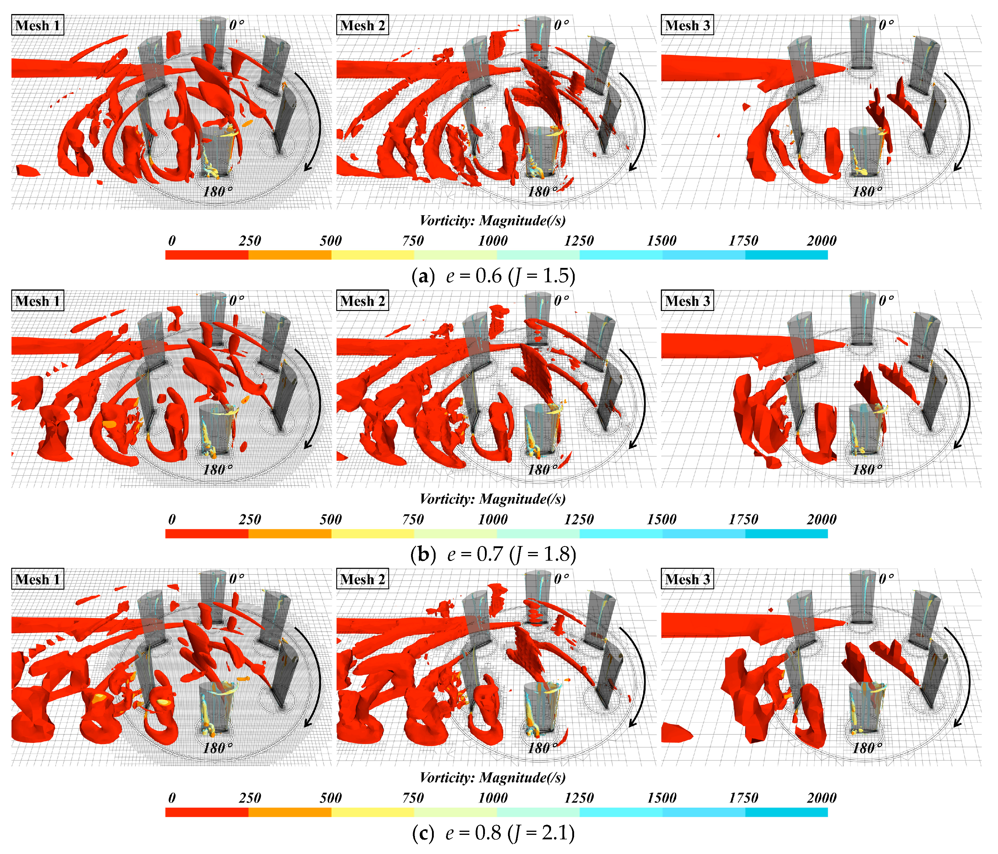
Based on the uncertainty-verified Medium mesh, three mesh sets are generated while maintaining identical VSP blade surface mesh and boundary layer dimensions. Mesh 1 parameters match those of the Medium mesh. Mesh 2 employs AMR technology with Level 2 refinement, adjusting mesh sizes in the rotation domain and wake region to ensure the post-refinement cell count equals that of Mesh 1. Mesh 3 uses no AMR but shares the initial mesh configuration with Mesh 2. Initial and maximum computational cell counts for the three mesh sets are presented in Table 6.
The key to adaptive mesh refinement lies in formulating appropriate adaptation criteria based on targeted physical quantities. To address unsteady wake issues caused by continuous large-scale variations in VSP blade-inflow angle of attack, Mesh Set 2 employs AMR technology using the novel omega vortex identification approach [36] as the mesh refinement criterion. This method excels at capturing both strong and weak vortices without requiring substantial threshold adjustments. The novel omega vortex identification approach decomposes vorticity into rotational and non-rotational components, introducing parameter Ω representing the ratio of rotational vorticity to total vorticity [37]. Dong et al. [38] identified that minuscule denominators in Ω calculations cause significant errors. Consequently, a small positive parameter ε is introduced to the denominator, with ε set to 0.001 based on extensive testing. The Ω expression is given in Equation (12).
Ω = B 2 F A 2 F + B 2 F + ε
In the equations, A denotes the symmetric tensor of the velocity gradient, and B represents the antisymmetric tensor of the velocity gradient. Their calculation formulas are given in Equations (13) and (14).
A = 1 2 ( V + V T ) = u x 1 2 ( u y + v x ) 1 2 ( u z + w x ) 1 2 ( u y + v x ) v y 1 2 ( v z + w y ) 1 2 ( u z + w x ) 1 2 ( v z + w y ) w z
B = 1 2 ( V V T ) = 0 1 2 ( u y v x ) 1 2 ( u z w x ) 1 2 ( v x u y ) 0 1 2 ( v z w y ) 1 2 ( w x u z ) 1 2 ( w y v z ) 0
As derived from the above equations, the parameter Ω ranges within [0, 1]. Unlike solids that rotate without deformation, vortices in fluid flows represent a mixture of vorticity and deformation. When Ω = 1, the fluid undergoes rigid-body rotation. When Ω > 0.5, vorticity dominates over deformation during vortex formation. Liu et al. [39] recommend Ω = 0.52 as the vortex identification criterion. Figure 6 displays the refined mesh distribution within the computational domain for Mesh Set 2 using AMR technology based on the novel Omega vortex identification approach. Comparison with the initial mesh demonstrates real-time automatic refinement according to vortex generation locations and flow trajectories.
Computations for maximum efficiency conditions at eccentricities e = 0.6, 0.7, and 0.8 are conducted using the three mesh configurations. By comparing thrust coefficient results and captured vorticity field details, the effectiveness of adaptive mesh technology in optimally distributing the refined mesh is validated. Thrust coefficient results for different eccentricities among the three meshes are presented in Table 7.
Comparison of thrust coefficient computation errors against experimental measurements in Table 7 shows that Mesh 2 exhibits smaller discrepancies across all three eccentricity conditions, with errors below 5%. Figure 7 shows isosurface vorticity distributions for the three mesh configurations.
From the definition of vorticity—the curl of fluid velocity vectors that represents the rotational speed of fluid particles around their own axes—it follows that substantial velocity gradients in boundary layers due to viscous effects often yield high vorticity even in vortex-free regions. Figure 7 reveals that, unlike vorticity-based vortex identification, the novel omega vortex identification approach more accurately captures complex vortex structures within the flow field. By integrating AMR technology, this method optimally distributes the refined mesh in the computational domain. Consequently, Mesh 2 resolves finer details of unsteady vortices generated by blade-coupled revolution and rotation motions. Based on the demonstrated simulation efficacy for VSP unsteady flow fields, flow-separation-induced vortex shedding, and validation of unsteady force computations, we confirm the feasibility of the AMR method grounded in the novel omega vortex identification approach. This establishes a robust numerical framework for simulating VSP unsteady hydrodynamics.

3. Results

3.1. VSP Unsteady Hydrodynamic Performance Analysis

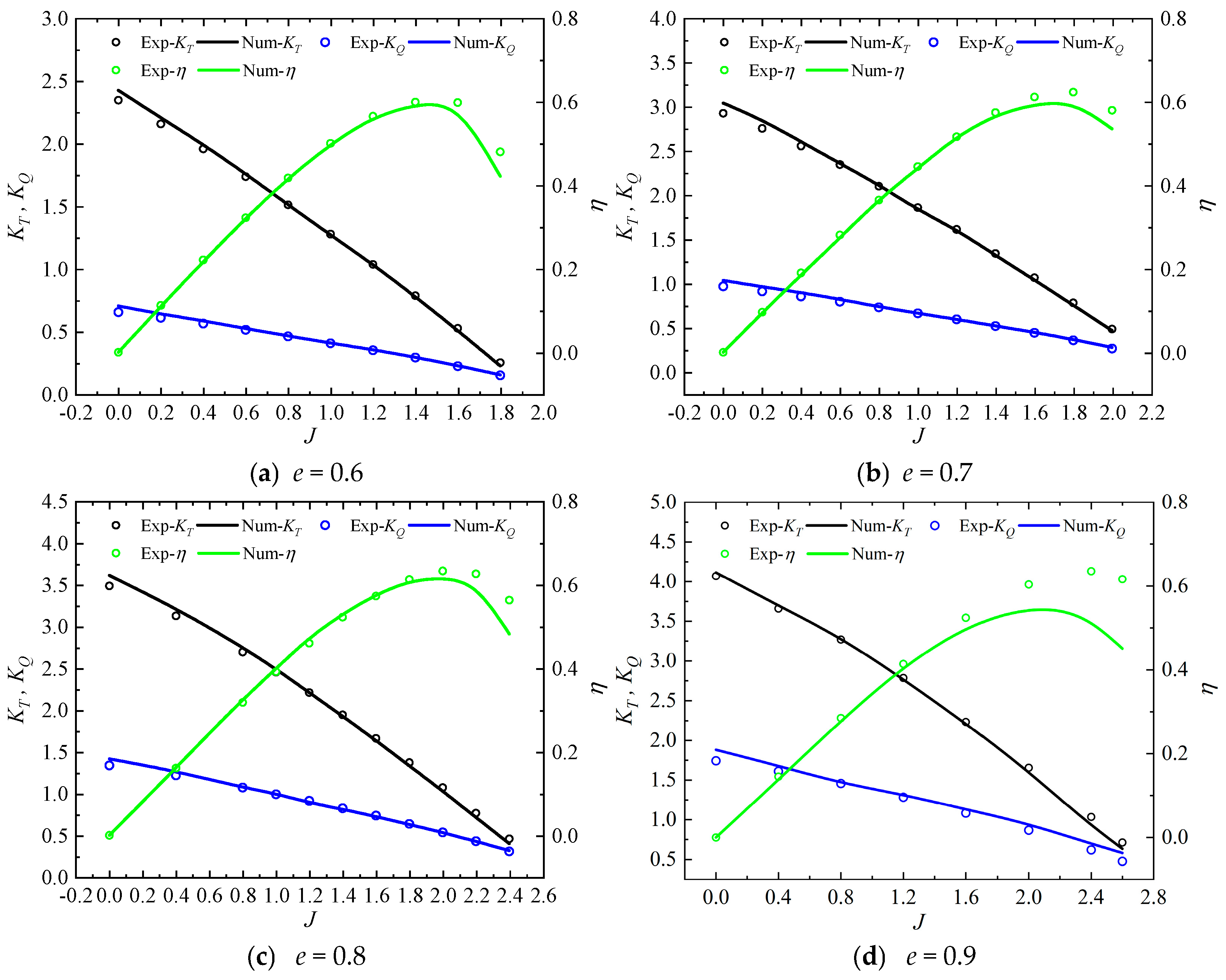
Compared to conventional propellers, VSP hydrodynamic generation relies on periodic variations in blade angle of attack along cycloidal trajectories during coupled rotation and revolution motions. Consequently, the combination of inflow velocity and eccentricity-induced blade deflection angles significantly impacts VSP hydrodynamic performance. To further investigate VSP hydrodynamic characteristics at varying advance coefficients under different eccentricities, open-water performance curves for e = 0.6–0.9 are computed using the validated VSP hydrodynamic numerical method, as shown in Figure 8.
Figure 8 demonstrates that the computed VSP open-water performance follows trends similar to conventional propellers with increasing advance coefficient. For eccentricities from 0.6 to 0.8, as eccentricity rises, thrust coefficient, torque coefficient, and efficiency curves exhibit upward shifts across the advance coefficient range. The effective thrust range also expands. Concurrently, the advance coefficient corresponding to peak efficiency increases with higher eccentricity. However, under high advance coefficients, drastic variations in blade-inflow angle of attack intensify flow separation and stall phenomena, elevating energy dissipation. Consequently, VSP peak efficiency is slightly lower than that of conventional propellers, and efficiency declines rapidly with further increases in advance coefficient.
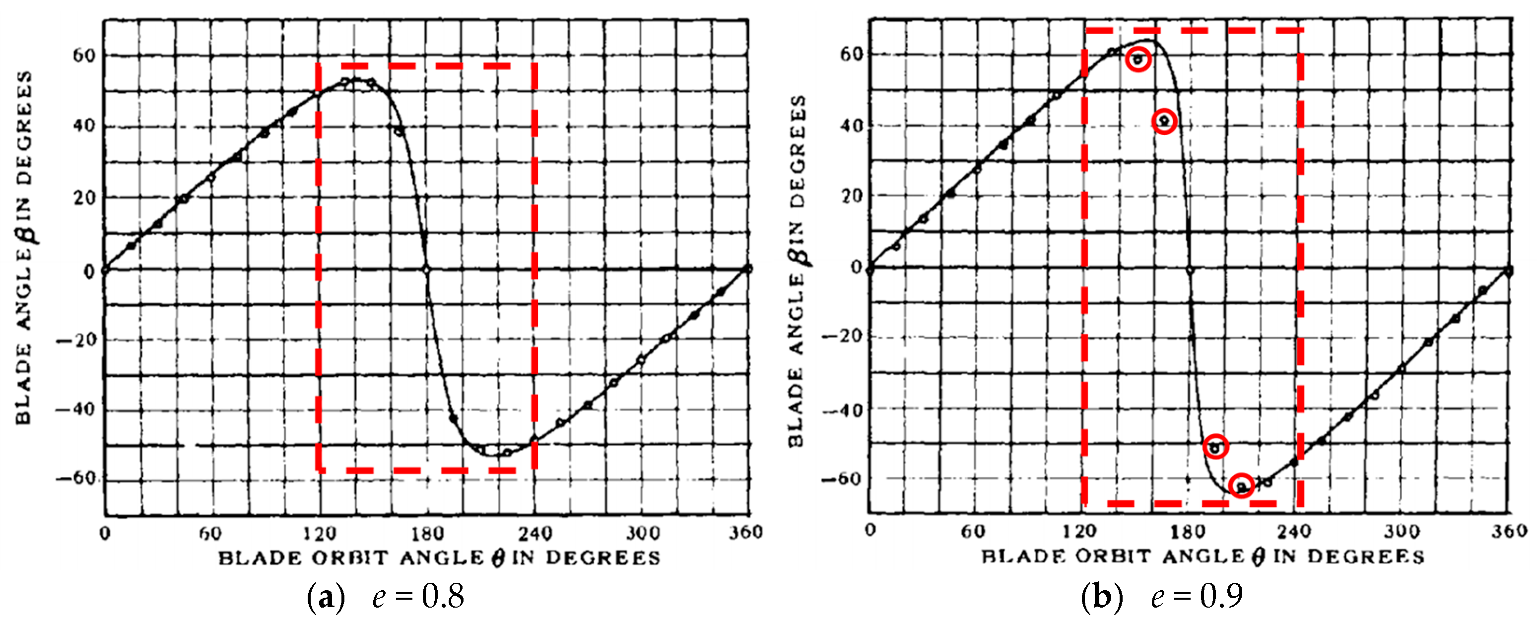
Compared with experimental data, numerical results for the e = 0.9 eccentricity condition show significant deviations. According to Ficken and Dickerson [28] in Test Report No. 2983, blade motion under varying eccentricities is achieved by replacing corresponding cams. However, constrained by mechanical structure, blade kinematics for high-eccentricity conditions were adapted, as depicted in Figure 9.
Figure 9 reveals significant deviation between monitored blade rotation deflection angles and theoretical curves. At e = 0.8, actual blade deflection aligns closely with the “chord-length normal intersection” theoretical curve. However, under e = 0.9 conditions, rapid blade flipping motion exhibits reduced rotation angles and angular velocity amplitudes, causing modified kinematics to diverge from theoretical predictions. Consequently, strictly adhering to the “chord-length normal intersection” strategy yields substantial errors between computed hydrodynamic values and experimental data for e = 0.9. Nevertheless, reducing rotation angle/velocity amplitudes significantly enhances VSP propulsion efficiency. To further investigate blade motion strategy impacts on VSP hydrodynamics, transient hydrodynamic forces on individual blades at peak efficiency conditions are analyzed in Figure 10 and Figure 11.
Figure 10 shows time history curves of revolution torque and rotation torque for a single blade over one motion cycle. As eccentricity increases under the “chord-length normal intersection” strategy, rapid blade flipping near 180° revolution angle causes corresponding rotation angles and angular velocities to surge, resulting in sharply increased rotation torque. Concurrently, Figure 11 reveals that instantaneous thrust near 180° revolution angle drops to negative values, intensifying hydrodynamic pulsation. Negative thrust occurs within revolution angle ranges of 0–60° and 150–180° during unsteady coupled motion. With rising eccentricity, the duration of negative-thrust revolution angle ranges shortens, but the magnitude of negative thrust increases.
During cycloidal propeller operation, energy consumption comprises revolution power and rotational power components. At constant revolution conditions, increasing blade motion eccentricity elevates peak rotation velocity and rotation torque, substantially raising the proportion of rotational power in total energy consumption. Consequently, while higher eccentricity enhances instantaneous efficiency within positive-thrust revolution angle ranges—consistent with general VSP hydrodynamic trends—the e = 0.9 condition induces a sharp rise in rotation torque. This significantly increases rotational power consumption and, coupled with zero effective power output during negative thrust phases, ultimately reduces overall efficiency.
In summary, unsteady hydrodynamic generation in VSP is closely correlated with blade-coupling motion strategies. As eccentricity increases, rotation angles and angular velocity amplitudes escalate rapidly. The superposition of blade-flow and blade-blade interactions forms transient flow fields characterized by unsteady flow and separation vortices, intensifying unsteady motion features. Consequently, this study will conduct further research through experimental measurements of VSP transient hydrodynamics.

3.2. Experimental Measurement Study of VSP Transient Hydrodynamic Forces

3.2.1. Test Platform Design

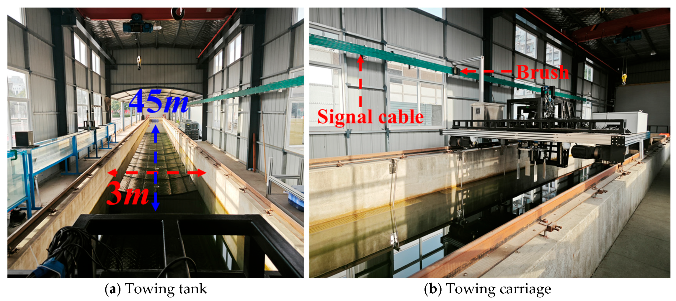
Analysis of VSP blade coupling motion trajectories and force distributions indicates that blades undergo rapid flipping motions near the eccentricity control points. As eccentricity increases, both flipping angle range and velocity escalate substantially. Initial mechanical implementations—using cams, crank linkages, and eccentric disk-slider-link mechanisms—often suffer from slow dynamic response, low propulsion efficiency, and severe component wear. To overcome mechanical limitations and achieve precise blade rotation angle control under high eccentricity, this study investigates transient plane vector thrust characteristics across varying eccentricities and analyzes blade motion-hydrodynamic interaction mechanisms. A cycloidal propeller device with servo-motor control was designed for a towing tank, comprising mechanical, control, and force measurement mechanisms. Figure 12 displays the towing tank and carriage.
Figure 12 shows the test platform and carriage model. The towing tank is divided into distinct sections: a dock section 5 m long, 2 m wide, and 3 m deep; and a test section 45 m long, 3 m wide, and 1.5 m deep. The carriage is equipped with a high-performance drive system offering a speed range of 0.01–2.1 m/s and speed control accuracy of ±0.01 m/s. Test conditions are adjustable by presetting carriage speed and position.
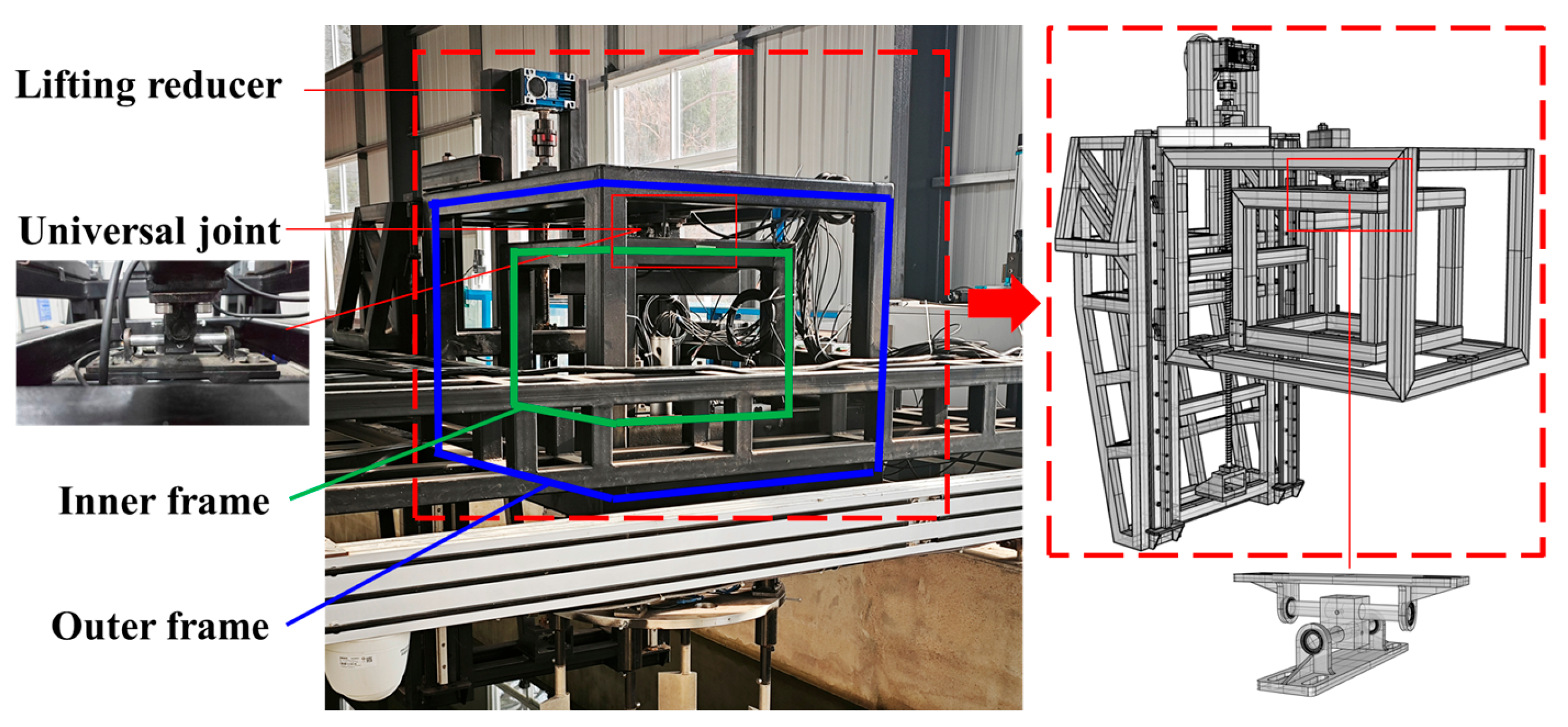
The mechanical mechanism, serving as the load-bearing structure of the cycloidal propeller, adopts a nested two-layer frame design with adjustable height. The outer frame connects to the support base and carriage platform via lifting rails. When raised to the top position, it facilitates manual debugging; when lowered, it allows free adjustment of propeller immersion depth according to water level while ensuring operational stability. The inner frame connects to the outer frame through a universal-joint suspension at the top. The cross-axis structure of the universal joint releases rotational degrees of freedom within the plane for the inner frame, enabling propeller thrust and side thrust to transmit via edge baffles to four-directional force sensors mounted on the outer frame. The actual assembly and corresponding model are shown in Figure 13.
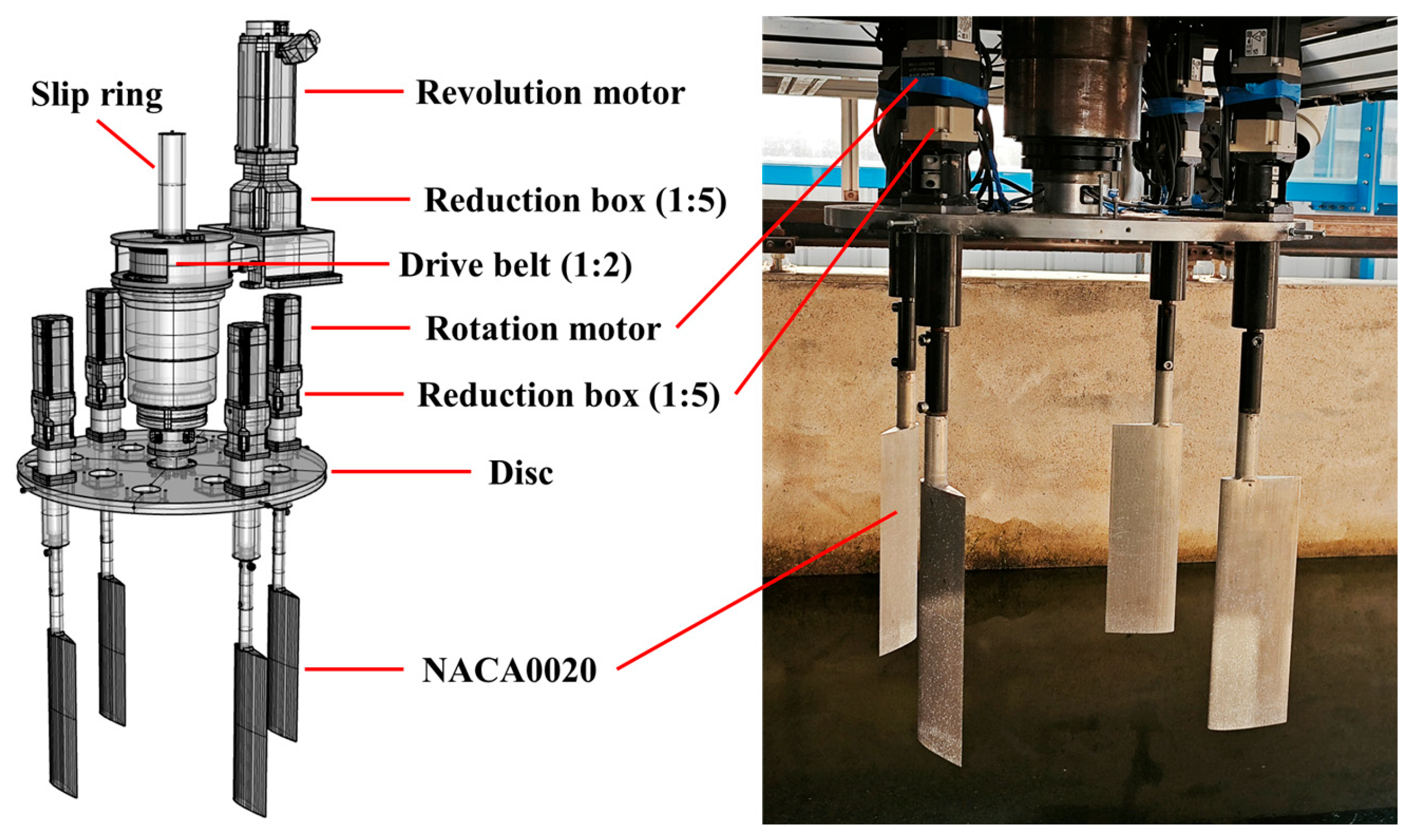
The control mechanism comprises hardware and software components. The hardware primarily consists of a main motor driving the propeller disk and sub-motors driving their respective blades, along with slip rings and gear reducers. Blade profiles adopt the NACA0020 airfoil. Each blade is independently controlled by a sub-motor. Encoder signals from sub-motors transmit through sliding contact between slip-ring brushes and rings, enabling data exchange with external stationary controllers during disk revolution. This design effectively reduces rotational mechanism loads and resolves cable entanglement issues. Gear reducers are integrated between blades and sub-motors to amplify output torque. The cycloidal propeller device is illustrated in Figure 14.
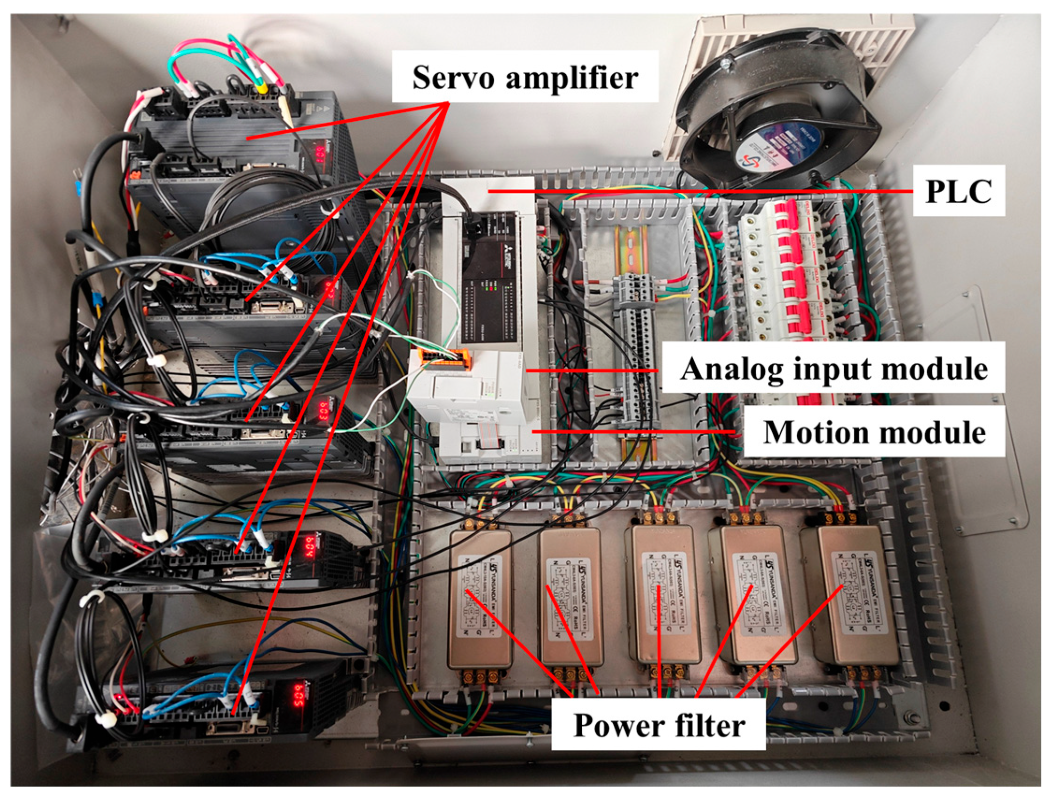
The software component comprises a multi-axis synchronous control system based on Mitsubishi servo motors. Using revolution angles and individual blade rotation deflection angles as control inputs, position target values for blade-driving sub-motors are set via the Programmable Logic Controller (PLC) programming to perform trajectory planning for multi-axis motion, calculating movement paths for all axes. The motion module computes axis trajectories and inter-axis relative positions based on real-time feedback from target trajectories, ensuring multi-axis synchronization. Simultaneously, the controller receives real-time position status feedback from servo motor encoders, continuously adjusts control parameters for motion correction, and guarantees synchronized motion across all axes. Figure 15 shows the control cabinet components, with primary devices listed in Table 8.
With the main propeller disk motor set at 60 r/min, Figure 16 illustrates blade motor rotation angles versus revolution angle for e = 0.7 and e = 0.9 conditions. Black curves denote theoretical values, while red points represent motor rotation angles sampled at 60 Hz from encoder feedback. During initial synchronization, path planning and dynamic compensation adjust blade motor angles according to positional discrepancies reported by encoders. Synchronization with the main motor is achieved within the first motion cycle, maintaining control errors within ±0.5°.
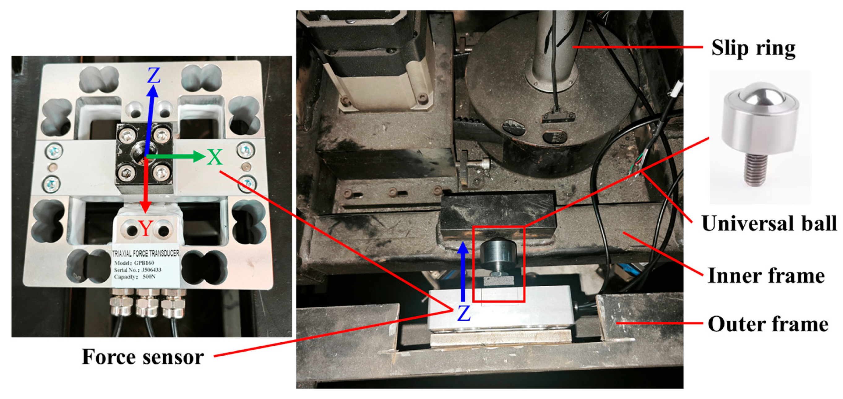
The force measurement mechanism consists of force sensors and ball-jointed rods mounted on the outer frame to measure VSP thrust. Force sensors are distributed around the baffles of the outer frame. Connecting rods press against inner frame baffles at symmetric positions, enabling transmission and measurement of propulsive thrust along the carriage direction and lateral/hydrodynamic forces in horizontal/vertical directions. To eliminate friction between connecting rods and inner frame baffles, each rod incorporates a ball joint with threaded studs. The stud end connects to sensors and is secured by locknuts, while the ball joint maintains point contact with inner frame baffles for friction-free mobility. This effectively eliminates frictional interference in force transmission. Figure 17 shows the sensor installation configuration.
The experiment employs GPB160 three-axis force sensors (Galoce., Xi’an, China). With sensors vertically mounted, thrust and side thrust measurements are based on the Z-direction. Given the height difference between the sensor measurement plane and the blade hydrodynamic center, lever arm effects amplify actual hydrodynamic forces in sensor readings. Thus, sensors with a 500 N range were selected. Calibration was performed using GT203 transmitters and matching handheld displays. Verification was conducted by applying fixed-weight counterweights post-calibration.

3.2.2. Test Platform Calibration and Testing

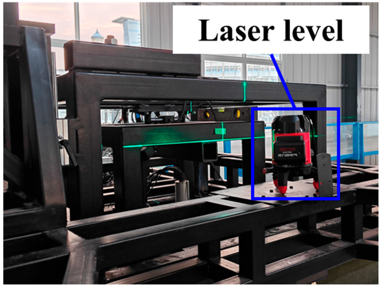
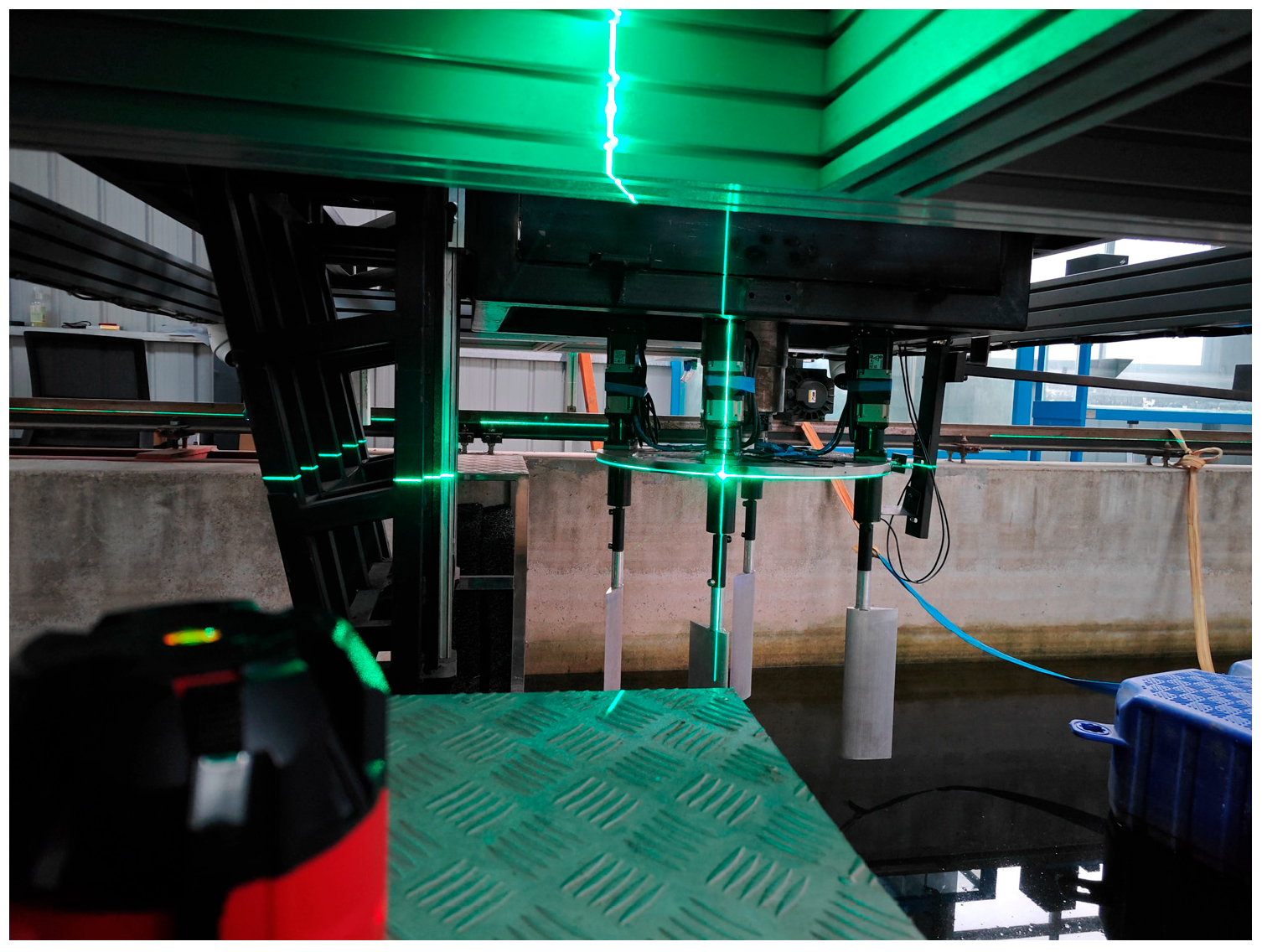
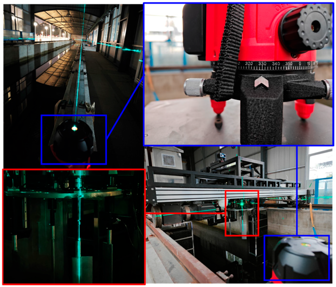
VSP hydrodynamic force measurements were conducted on the towing tank carriage platform. Blades connect to the propeller disk and transmit hydrodynamic reaction forces to the inner frame positioned above. The inner frame then transfers forces in different directions to corresponding sensors via connecting rods. During this process, continuous revolution of the disk and blade rotation occur. To prevent force measurement errors caused by inner frame tilting, the center of gravity is calibrated by altering the locking point of the top universal joint. This enables static balance calibration of the inner frame and dynamic balance calibration of the propeller disk. Figure 18 and Figure 19, respectively, show static and dynamic balance calibration using a laser leveler.
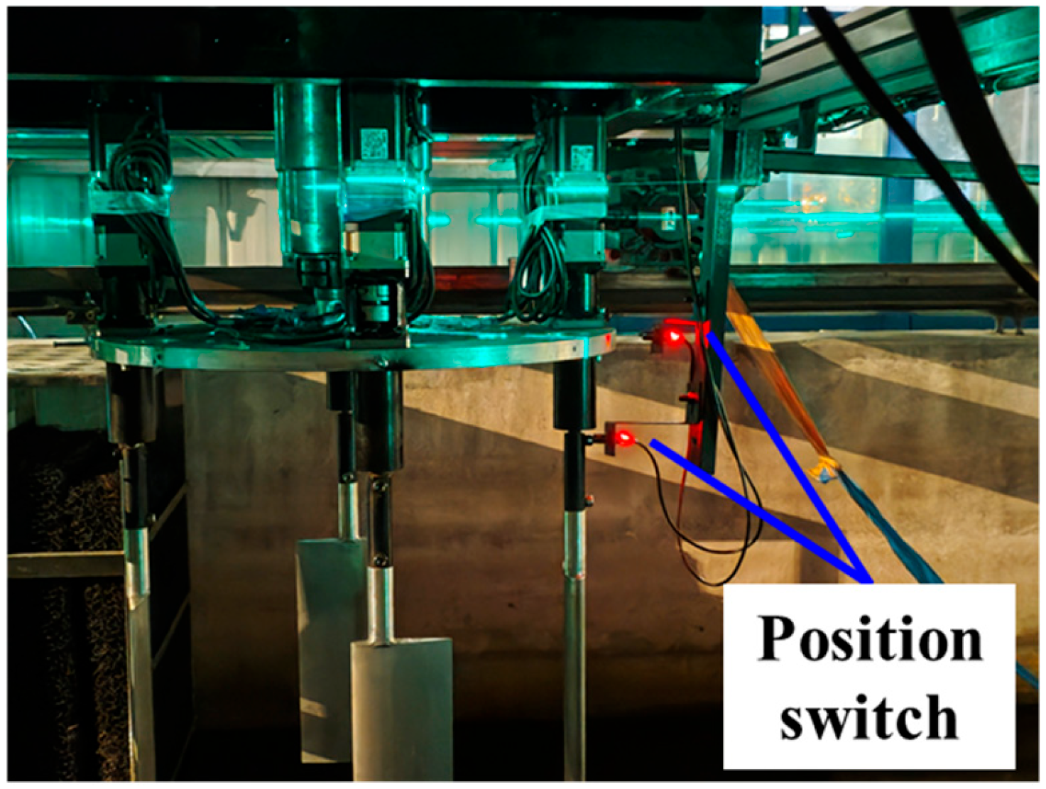
All test conditions maintain the identical initial position. The propeller disk zero position is defined as the configuration where initial thrust aligns with the forward direction, with each blade’s chord direction adjusted tangentially to its revolution path. To ensure measured thrust aligns with the carriage direction, a horizontal bracket installed ahead of the carriage provides preliminary zero-position verification via position switches. Guide wheels mounted beside the carriage enforce strict alignment with the tank rails. Independent control of main and sub-motors adjusts disk and blade positions, while laser levels and rail geometries enable angular calibration to confirm disk and blade zero positions. Post-calibration, force data variations and laser markers verify horizontal alignment and zero positions across speeds. Figure 20 shows preliminary disk zero verification using position switches; Figure 21 confirms blade deflection angles via laser-aligned blade shafts.

3.2.3. Experimental Results and Simulation

Considering the towing tank dimensions, device load capacity, and sensor measurement ranges, propeller disk diameter and blade shape parameters were determined. The blade rotation shaft is positioned at the maximum thickness location of the NACA0020 airfoil profile (30% chord length from the leading edge). Blade tips were positioned 5 cm below the water surface. Based on the VSP electro-control experimental design, transient plane vector thrust measurements were conducted under various eccentricities. The propeller revolution speed was set at 60 r/min, with carriage speeds ranging from 0 to 1.0 m/s. VSP model parameters are listed in Table 9.
Based on the numerical simulation method validated against Test Report No. 2983, modeling referenced the towing tank configuration. Accounting for the gas–liquid two-phase environment with a free surface, vertical mesh refinement was applied to the free-surface region while maintaining identical turbulence modeling and meshing approaches. Figure 22 shows the computational domain partitioning and local mesh generation around the propeller.
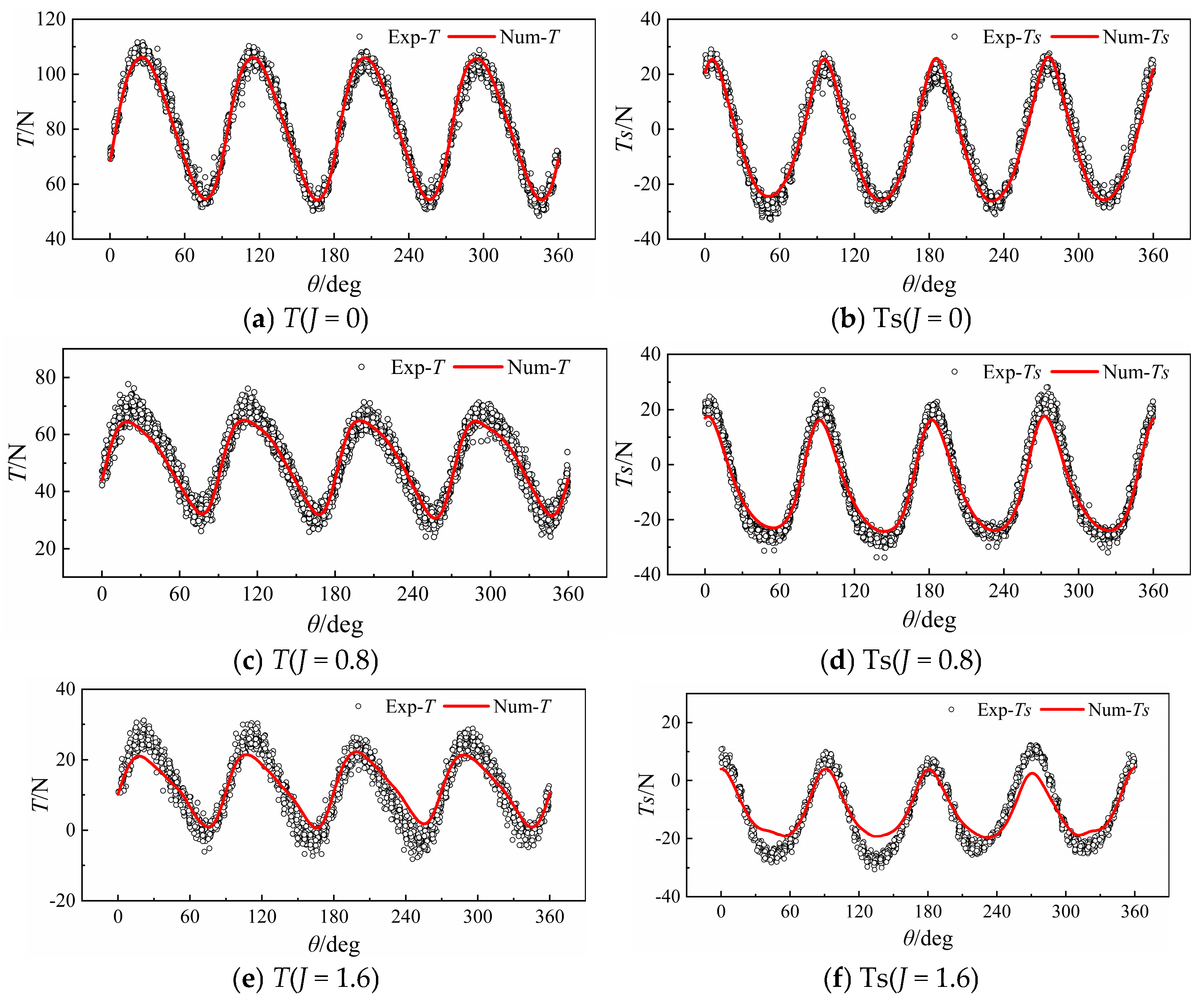
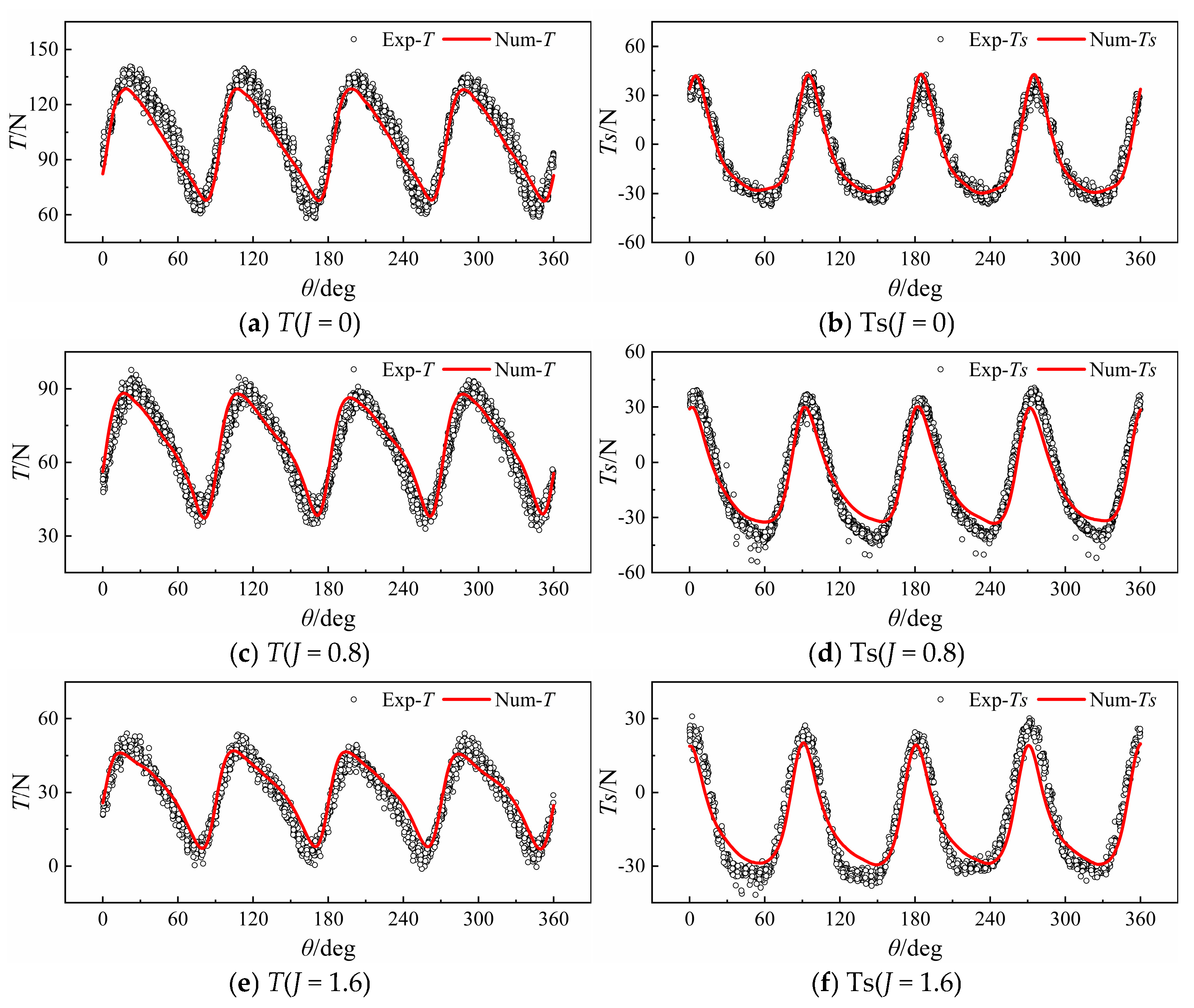
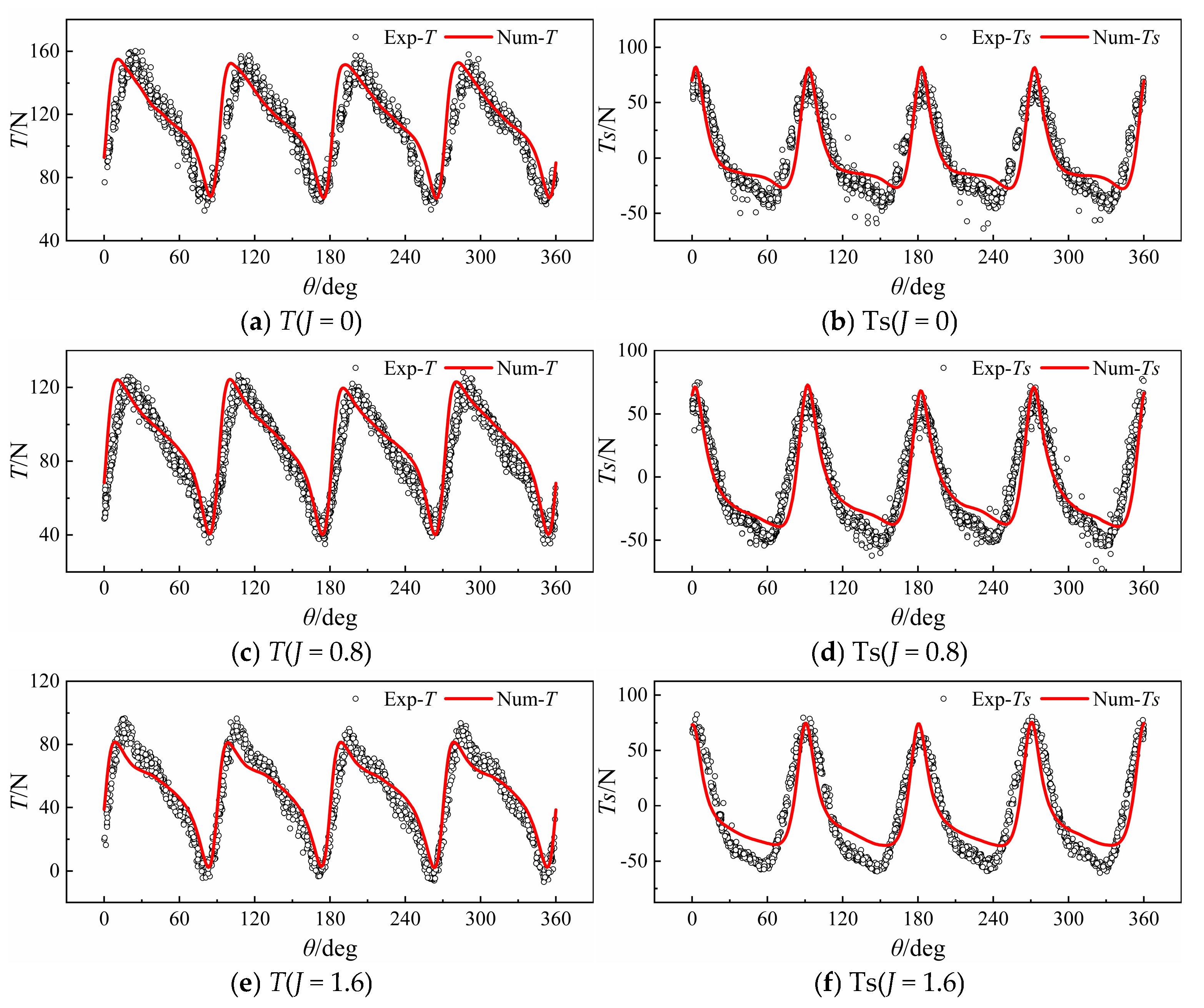
To further verify the feasibility of experimental measurement methods and numerical simulation accuracy for VSP plane vector thrust nonlinear variations, transient hydrodynamic time-history data from blade-coupled motion dynamics was analyzed through experimental and numerical results. During measurements, unsteady coupled blade motion induces high-frequency vibrations in sensor mounts, brackets, and test platforms. To preserve low-frequency thrust dynamics while attenuating high-frequency noise and extraneous vibrations, frequency-domain analysis was applied to thrust and side thrust data over multiple motion cycles. A low-pass filter based on second-order blade-passing frequency was implemented. Comparative transient time-history curves for thrust and side thrust are shown in Figure 23, Figure 24, Figure 25 and Figure 26.
Figure 23, Figure 24, Figure 25 and Figure 26 show transient time-history curves of experimental and numerically simulated thrust and side thrust. Across eccentricity conditions, numerical results and experimental measurements exhibit consistent trends with variations in advance coefficient, which validates the synchronous motion control based on servo motors and the cross-verification of plane vector thrust measurement and numerical methods for VSP.
As eccentricity increases, thrust and side thrust peaks rise with increased fluctuation amplitudes, exacerbating asymmetry between positive and negative side thrust extremes. At e = 0.9, peak growth exhibits nonlinear abrupt changes. The periodic coupled motion of the VSP’s four blades produces four fixed peaks/troughs in thrust and side thrust curves. While fluctuation frequencies remain constant with rising eccentricity, curve steepness intensifies significantly. This indicates that higher eccentricity amplifies blade rotation deflection angles and angular velocity at flipping positions, causing more drastic variations in blade-inflow attack angles. Transient time-history curves reveal discrepancies between numerical and experimental values at revolution angles such as 60°, 150°, 240°, and 330°—where side thrust reaches negative maxima—as numerical waveforms fail to match experimental measurements. Considering phase-consistent blade motion strategies, hydrodynamic variations are analyzed through cycloidal propeller velocity fields. Figure 27 presents mid-span blade velocity contours at J = 1.6.
As shown in the velocity contour plot in Figure 27, when the eccentricity increases from e = 0.6 to e = 0.9, the flow field around the blade at the 180° revolution angle exhibits more distinct differences between the positive and negative velocity regions on both sides of the blade, indicating an acceleration of the blade flipping motion and a significant enhancement in local flow velocity. Meanwhile, the accelerated flipping motion leads to a substantial change in the angle of attack relative to the incoming flow, which is also one of the contributing factors to flow separation. Flow separation at the cross-section is identified by the presence of vortices and low-speed regions. Under eccentricity conditions of e = 0.6 and e = 0.7, the velocity distribution around the blade remains relatively uniform, suggesting no significant flow separation. In contrast, at e = 0.8 and e = 0.9, pronounced low-speed and high-speed regions emerge around the blade, causing flow separation and vortex formation on the blade surface. Therefore, during the blade flipping motion, the substantial change in the angle of attack combined with the inertial force from the accelerated rotation induces flow separation at the mid-span section. This separation then propagates backward under the influence of the blade motion and the incoming flow, resulting in a turbulent flow field dominated by turbulence and vortices near the revolution angle of 240°. It can be concluded that under the nonlinear interference caused by flow separation during rapid blade flipping, the numerical results show high agreement with experimental measurements under low-eccentricity conditions, with consistent curve trends. However, at high eccentricity, flow separation and vortex shedding on the blade surface intensify, making the unsteadiness of thrust and side thrust more complex and difficult to accurately predict numerically, which is the main source of error between numerical and experimental results.
Figure 23, Figure 24, Figure 25 and Figure 26 illustrate transient hydrodynamic forces from four-blade coupled superposition. As the advance coefficient increases, effective blade attack angles decrease, resulting in declining thrust amplitude and mean values. Negative thrust occurs at specific angles under high advance coefficients. Side thrust exhibits periodic nonlinear variations in both directions during the coupled motion cycle due to blade deflection angle changes, causing periodic deflection of the synthesized VSP plane vector thrust within angular ranges. Consequently, transient time-history data was non-dimensionalized to derive time-averaged thrust coefficients and side thrust coefficients across advance coefficients. Figure 28 presents experimental and numerical variation curves of VSP thrust and side thrust coefficients for eccentricities from 0.6 to 0.9.
Figure 28 reveals that across eccentricity conditions, experimental and numerical results for VSP thrust and side thrust coefficients exhibit consistent trends with minimal global discrepancies. Unlike thrust coefficients, which vary linearly with advance coefficient, side thrust coefficients exhibit near-linear behavior at low advance coefficients. When the advance coefficient increases to J = 0.8, side thrust demonstrates nonlinear variation trends that differ across eccentricity conditions.
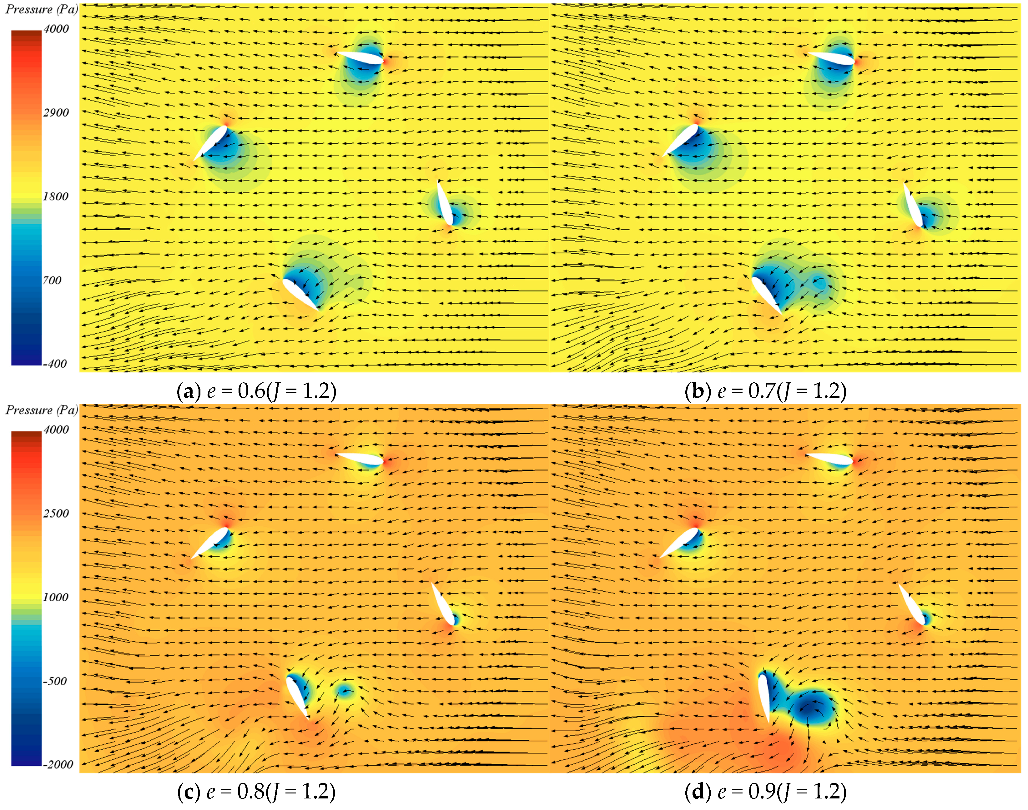
Time-averaged data analysis indicates the following: Thrust aligns with the propulsion direction, where resultant lift and drag forces show near-linear proportionality to flow velocity variations in thrust components. Increased advance coefficients induce dynamic stall and flow separation leading to unsteady vortex shedding. Despite dynamic stall, blade thrust remains dominated by pressure differentials along the inflow direction. Higher inflow velocity linearly reduces effective attack angles, causing uniform thrust attenuation in blade lift components. Although flow separation intensifies, instantaneous lift fluctuations across blades mutually cancel during integration, leaving thrust to reflect only the averaged effect of reduced attack angles—hence the near-linear thrust coefficient variation with advance coefficient. To further analyze the nonlinear variation in the side thrust coefficient with the advance coefficient, Figure 29 presents visualization results of pressure contours and velocity streamlines at the mid-span section of the VSP blade for J = 1.2.
Based on the pressure contours and velocity streamlines in Figure 29, it can be observed that the side thrust is primarily generated by the asymmetric flow distribution on both sides of the blade. The distribution on the suction and pressure surfaces of the blade is influenced by the combined effects of incoming flow velocity and rotational velocity, resulting in a lateral pressure gradient under different eccentricity conditions. As the blade rotates to different positions, the surrounding flow separation and vortex shedding exhibit significant asymmetry. The periodic rotation of the blade alters the local flow field and pressure distribution, causing dynamic changes in the pressure difference direction across the blade, which ultimately manifests as alternating positive and negative side thrust. From the variation curve of the side thrust coefficient with the advance coefficient in Figure 28, it can be observed that under low advance coefficient conditions, the side thrust curve decreases or increases approximately linearly with the advance coefficient, indicating weak flow separation on the blade surface and minimal large-scale boundary layer separation. In this regime, the side thrust is predominantly governed by the lift component, with negligible dynamic effects. In contrast, under high advance coefficient conditions, the side thrust coefficient curve exhibits a distinct abrupt change in slope, which is a typical characteristic of dynamic stall. Dynamic stall and flow separation trigger unsteady vortex shedding, and instantaneous differences in the position and intensity of the vortex core cause significant fluctuations in the side thrust, exhibiting nonlinear behavior. Furthermore, as the eccentricity increases, the fluctuations in the side thrust coefficient curve become more pronounced, reflecting increased instability in flow separation and more evident dynamic stall phenomena.
Therefore, the occurrence of dynamic stall and flow separation can be identified by nonlinear abrupt changes in the side thrust. Combined with the linear characteristics of the thrust coefficient, this helps distinguish between the different responses of the axial and lateral components of lift. Furthermore, an increase in eccentricity generally exacerbates flow unsteadiness and non-uniformity in lift distribution.
In summary, time-averaged coefficients and time-history curves confirm that numerical simulations and experimental measurements exhibit consistent trends for thrust and side thrust, achieving mutual validation of servo-motor-based synchronous motion control and transient hydrodynamic measurement/numerical methods for cycloidal propellers. The unique configuration of VSP blades—with rotation axes perpendicular to the inflow direction—causes downstream blades to operate within the wake of upstream blades. Consequently, downstream blades undergo variable-speed rotations while coupled with non-uniform upstream wakes, generating asymmetric flow fields that constitute the primary source of side thrust. Simultaneously, abrupt changes in rotational angular velocity during rapid blade flipping near control points induce strong fluid–structure interactions. Coupled with separated flows and shed vortices, these interactions further amplify flow asymmetry—the fundamental cause of nonlinear side thrust variations.

4. Conclusions

This study targets the unsteady hydrodynamics of VSP, focusing on its transient hydrodynamic characteristics during blade coupled motion. Systematic numerical simulations and experimental investigations on VSP hydrodynamic performance were conducted. Based on force analysis during blade coupled motion and nonlinear flow interactions, an unsteady hydrodynamic numerical method was established using publicly available test data. Numerical accuracy was enhanced through the Ω-vortex criterion for vortex-adaptive mesh refinement. Numerically, variation patterns of VSP unsteady transient hydrodynamics with eccentricity were analyzed considering blade motion coupling. Experimentally, a VSP plane-vector-thrust measurement platform was developed. The feasibility of servo-motor-based blade synchronous motion control, thrust measurement, and numerical methods was evaluated, with further analysis of VSP unsteady transient hydrodynamic characteristics. The main conclusions follow:
(1) Based on the coupled motion characteristics of steady revolution and unsteady rotation in VSP cycloidal propellers, unsteady hydrodynamic features during large attack angle variations were investigated. A hydrodynamic numerical method was established, combining vortex identification with adaptive meshing according to VSP unsteady flow characteristics, enhancing computational accuracy.
(2) As eccentricity increases under the “chord-normal intersection” motion strategy, peak blade rotation angular velocity rises sharply, intensifying unsteady effects and causing nonlinear growth in VSP hydrodynamic pulsation amplitudes. At constant revolution, higher eccentricity significantly increases rotation power’s proportion to total power, becoming the key factor limiting propulsion efficiency.
(3) VSP transient hydrodynamic calculations and experimental measurements reveal that side thrust exhibits periodic nonlinear positive/negative variations with blade deflection angles. This results in periodic deflection of synthesized plane-vector thrust within specific angular ranges, accompanied by transient negative thrust intervals at high advance coefficients, necessitating hydrodynamic pulsation optimization.
(4) For side thrust coefficient nonlinearity with increasing advance coefficient, flow separation during rapid blade flipping near eccentricity control points—amplified by coupled separated flow and shed vortices—is identified as the primary cause of asymmetric flow distribution driving nonlinear side thrust variations.
(5) Mutual verification of VSP synchronous motion control systems and transient hydrodynamic measurement/numerical methods was achieved through experimental and simulated data. Future work will focus on hydrodynamic optimization of coupled blade motion strategies, though test platform stability requires enhancement.
Author Contributions

Conceptualization, W.L. and Z.L.; methodology, W.L.; software, W.L.; validation, W.L., W.X. and Q.C.; formal analysis, W.L.; investigation, W.X.; resources, Z.L.; data curation, W.L.; writing—original draft preparation, W.L.; writing—review and editing, Z.L.; visualization, W.X.; supervision, Q.C.; project administration, Z.L.; funding acquisition, Z.L. All authors have read and agreed to the published version of the manuscript.

Funding

This research was funded by the National Natural Science Foundation of China, grant number 52371343.

Data Availability Statement

The original contributions presented in this study are included in the article. Further inquiries can be directed towards the corresponding author.

Conflicts of Interest

The authors declare no conflicts of interest.

References

  1. Desai, M.; Halder, A.; Benedict, M.; Young, Y.L. A Control Scheme for 360° Thrust Vectoring of Cycloidal Propellers with Forward Speed. Ocean. Eng. 2022, 249, 110833. [Google Scholar] [CrossRef]
  2. Altosole, M.; Donnarumma, S.; Spagnolo, V.; Vignolo, S. Performance Simulation of Marine Cycloidal Propellers: A Both Theoretical and Heuristic Approach. J. Mar. Sci. Eng. 2022, 10, 505. [Google Scholar] [CrossRef]
  3. Jürgens, D.; Palm, M.; Turbo, V. Influence of Thruster Response Time on Dp Capability by Time-Domain Simulations. In Proceedings of the Marine Technology Society-DP Conference, Berlin/Heidelberg, Germany, 10–11 October 2017. [Google Scholar]
  4. Schneider, E. Blade Wheel. U.S. Patent 1681500, 21 August 1928. Available online: https://patents.google.com/patent/US1681500 (accessed on 22 August 2025).
  5. Kirsten, J. Propeller. U.S. Patent 1432700, 17 October 1922. Available online: https://patents.google.com/patent/US1432700 (accessed on 22 August 2025).
  6. Voith. Available online: https://voith.com/corp-en/index.html (accessed on 22 August 2025).
  7. Just, W. Theories Des Voith-Schneider-Propellers; Springer: Berlin/Heidelberg, Germany, 1939. [Google Scholar]
  8. Isay, W.H. Calculation of the Flow through Voith-Schneider Propellers. Transl. Ing.-Arch. 1956, 24, 148–170. [Google Scholar] [CrossRef]
  9. Taniguchi, K. Approximate Solution of Voith-Sohneider Propeller. J. Zosen Kiokai 1952, 1952, 153–161. [Google Scholar] [CrossRef]
  10. Taniguchi, K. Hydrodynamical Investigations of the Blade-Wheel-Propellers (2nd Report). J. Zosen Kiokai 1955, 1955, 63–74. [Google Scholar] [CrossRef] [PubMed]
  11. Taniguchi, K. Studies on a Trochoidal Propeller. Ph.D. Thesis, Tokyo University, Tokyo, Japan, 1960. [Google Scholar]
  12. Mendenhall, M.R.; Spangler, S.B. Theoretical Analysis of Cycloidal Propellers; Part II. Program Manual; Defense Technical Information Center (DTIC): Fort Belvoir, VA, USA, 1973. [Google Scholar]
  13. Prabhu, J.; Nagarajan, V.; Sha, O.P. Unsteady Flow Analysis of Marine Cycloidal Propeller. In Proceedings of the International Conference on Ship & Offshore Technology Coastal & Inland Shipping, Kharagpur, India, 10–11 December 2015; pp. 10–11. [Google Scholar]
  14. Prabhu, J.J.; Nagarajan, V.; Sunny, M.R.; Sha, O.P. On the Fluid Structure Interaction of a Marine Cycloidal Propeller. Appl. Ocean. Res. 2017, 64, 105–127. [Google Scholar] [CrossRef]
  15. Halder, A.; Walther, C.; Benedict, M. Hydrodynamic Modeling and Experimental Validation of a Cycloidal Propeller. Ocean. Eng. 2018, 154, 94–105. [Google Scholar] [CrossRef]
  16. Epps, B.P.; Roesler, B.T.; Medvitz, R.B.; Choo, Y.; McEntee, J. A Viscous Vortex Lattice Method for Analysis of Cross-Flow Propellers and Turbines. Renew. Energy 2019, 143, 1035–1052. [Google Scholar] [CrossRef]
  17. Hu, J.; Li, T.; Guo, C. Two-Dimensional Simulation of the Hydrodynamic Performance of a Cycloidal Propeller. Ocean. Eng. 2020, 217, 107819. [Google Scholar] [CrossRef]
  18. Hu, J.; Li, T.; Wang, J.; Zhang, W.; Guo, C. Numerical Study on Vortex Shedding of Cycloidal Propellers. J. Mar. Sci. Technol. 2021, 26, 1217–1236. [Google Scholar] [CrossRef]
  19. Yan, H.; Lei, M.; Li, Z.; Zhou, Z.; Gai, Q.; Xia, D. Research on Key Influencing Factors of Hydrodynamic Performance for a Class of Planar Linkage Mechanism Cycloidal Propellers. In Proceedings of the 2023 IEEE International Conference on Robotics and Biomimetics (ROBIO), Koh Samui, Thailand, 4–9 December 2023; IEEE: New York, NY, USA, 2023; pp. 1–6. [Google Scholar]
  20. Hu, J.; Yan, Q.; Sun, S.; Li, F.; Ma, J. Numerical Simulation to Assess Hydrodynamic Performance of Cycloidal Propellers during Maneuvering. Ocean. Eng. 2023, 273, 113931. [Google Scholar] [CrossRef]
  21. Liu, Z.; Yan, H.; Shi, Z.; Xia, D. Two-Dimensional Dynamics CFD Simulation of Voith-Schneider Cycloidal Propeller. In Proceedings of the 2023 IEEE International Conference on Mechatronics and Automation (ICMA), Harbin, China, 6–9 August 2023; IEEE: New York, NY, USA, 2023; pp. 1395–1400. [Google Scholar]
  22. Roesler, B.T.; Kawamura, M.L.; Miller, E.; Wilson, M.; Brink-Roby, J.; Clemmenson, E.; Keller, M.; Epps, B.P. Experimental Performance of a Novel Trochoidal Propeller. J. Ship Res. 2016, 60, 48–60. [Google Scholar] [CrossRef]
  23. Fasse, G.; Becker, F.; Hauville, F.; Astolfi, J.-A.; Germain, G. An Experimental Blade-Controlled Platform for the Design of Smart Cross-Flow Propeller. Ocean. Eng. 2022, 250, 110921. [Google Scholar] [CrossRef]
  24. Jürgens, B.; Fork, W. The Fascination of the Voith-Schneider Propeller: History and Engineering; Koehlers Verlagsgesellschaft mbH: Nordrhein-Westfalen, Germany, 2002; ISBN 3-7822-0859-5. [Google Scholar]
  25. Hu, J.; Yan, Q.; Ding, J.; Sun, S. Numerical Study on Transient Four-Quadrant Hydrodynamic Performance of Cycloidal Propellers. Eng. Appl. Comput. Fluid Mech. 2022, 16, 1813–1832. [Google Scholar] [CrossRef]
  26. Jürgens, D.; Palm, M.; Singer, S.; Urban, K. Numerical Optimization of the Voith-Schneider® Propeller. ZAMM-J. Appl. Math. Mech. 2007, 87, 698–710. [Google Scholar] [CrossRef]
  27. Roesler, B.T.; Francsiquez, M.; Epps, B.P. Design and Analysis of Trochoidal Propulsors Using Nonlinear Programming Optimization Techniques. In Proceedings of the International Conference on Offshore Mechanics and Arctic Engineering; American Society of Mechanical Engineers, San Francisco, CA, USA, 8–13 June 2014; Volume 45516, p. V08BT06A032. [Google Scholar]
  28. Ficken, N.L.; Dickerson, M.C. Experimental Performance and Steering Characteristics of Cycloidal Propellers (No. NSRDC-2983); David W Taylor Naval Ship Research and Development Center: Bethesda, MD, USA, 1969. [Google Scholar]
  29. Zhang, X.; Zhang, L.; Wang, F.; Zhao, D.; Pang, C. Research on the Unsteady Hydrodynamic Characteristics of Vertical Axis Tidal Turbine. China Ocean. Eng. 2014, 28, 95–103. [Google Scholar] [CrossRef]
  30. Bakhtiari, M.; Ghassemi, H.; Sakaki, A.; He, G. Optimisation Scheme Applied to the Voith-Schneider Propulsion System Using Genetic Algorithm. Ships Offshore Struct. 2021, 16, 650–658. [Google Scholar] [CrossRef]
  31. Zhao, D.J.; Wang, Y.K.; Cao, W.W.; Zhou, P. Optimization of Suction Control on an Airfoil Using Multi-Island Genetic Algorithm. Procedia Eng. 2015, 99, 696–702. [Google Scholar] [CrossRef]
  32. Zhai, S.; Jin, S.; Chen, J.; Liu, Z.; Song, X. CFD-Based Multi-Objective Optimization of the Duct for a Rim-Driven Thruster. Ocean. Eng. 2022, 264, 112467. [Google Scholar] [CrossRef]
  33. Wilson, R.; Stern, F. Verification and Validation for RANS Simulation of a Naval Surface Combatant. In Proceedings of the 40th AIAA Aerospace Sciences Meeting & Exhibit, Reno, Nevada, 14–17 January 2002; p. 904. [Google Scholar]
  34. Roache, P.J. Criticisms of the “Correction Factor” Verification Method. J. Fluids Eng. 2003, 125, 732–733. [Google Scholar] [CrossRef]
  35. Golay, F.; Ersoy, M.; Yushchenko, L.; Sous, D. Block-Based Adaptive Mesh Refinement Scheme Using Numerical Density of Entropy Production for Three-Dimensional Two-Fluid Flows. Int. J. Comput. Fluid Dyn. 2015, 29, 67–81. [Google Scholar] [CrossRef]
  36. Liu, C.; Wang, Y.; Yang, Y.; Duan, Z. New Omega Vortex Identification Method. Sci. China Phys. Mech. Astron. 2016, 59, 684711. [Google Scholar] [CrossRef]
  37. Xiang, G.; Ou, Y.; Chen, J.; Wang, W.; Wu, H. A Study on the Influence of Unsteady Forces on the Roll Characteristics of a Submarine during Free Ascent from Great Depth. J. Mar. Sci. Eng. 2024, 12, 757. [Google Scholar] [CrossRef]
  38. Dong, X.; Wang, Y.; Chen, X.; Dong, Y.; Zhang, Y.; Liu, C. Determination of Epsilon for Omega Vortex Identification Method. J. Hydrodyn. 2018, 30, 541–548. [Google Scholar] [CrossRef]
  39. Liu, C.; Gao, Y.; Dong, X.; Wang, Y.; Liu, J.; Zhang, Y.; Cai, X.; Gui, N. Third Generation of Vortex Identification Methods: Omega and Liutex/Rortex Based Systems. J. Hydrodyn. 2019, 31, 205–223. [Google Scholar] [CrossRef]
Figure 1. Coupled Motion of VSP Blades.
Jmse 13 01933 g001
Figure 2. Rotation Deflection Angle and Rotation Angular Velocity of VSP Under Different Eccentricities.
Jmse 13 01933 g002
Figure 3. Blade Model and Computational Domain Division.
Jmse 13 01933 g003
Figure 4. Reference mesh.
Jmse 13 01933 g004
Figure 5. Adaptive Mesh Refinement Levels.
Jmse 13 01933 g005
Figure 6. Adaptive Mesh Refinement Changes.
Jmse 13 01933 g006
Figure 7. Vorticity Plots for Different Mesh Schemes Under Three Eccentricity Conditions.
Jmse 13 01933 g007
Figure 8. VSP Open-Water Performance Curves Under Different Eccentricity Conditions.
Jmse 13 01933 g008
Figure 9. Monitored Blade Rotation Angles vs. Theoretical Curves (Test Report No. 2983).
Jmse 13 01933 g009
Figure 10. Torque of revolution and torque of rotation.
Jmse 13 01933 g010
Figure 11. Thrust coefficient and efficiency.
Jmse 13 01933 g011
Figure 12. Towing tank and towing carriage.
Jmse 13 01933 g012
Figure 13. Mechanical structure device.
Jmse 13 01933 g013
Figure 14. VSP model.
Jmse 13 01933 g014
Figure 15. Control cabinet.
Jmse 13 01933 g015
Figure 16. Rotation angle variation curve of the blade motor.
Jmse 13 01933 g016
Figure 17. Assembly diagram of the force sensor.
Jmse 13 01933 g017
Figure 18. Static balance calibration of inner frame.
Jmse 13 01933 g018
Figure 19. Dynamic balance calibration of propeller disk.
Jmse 13 01933 g019
Figure 20. Zero point determination of position switch.
Jmse 13 01933 g020
Figure 21. Zero point determination of laser positioning.
Jmse 13 01933 g021
Figure 22. Computational Domain Partitioning for VSP Numerical Simulation under Test Conditions.
Jmse 13 01933 g022
Figure 23. Transient time-history curves of experimental vs. numerical thrust (e = 0.6).
Jmse 13 01933 g023
Figure 24. Transient time-history curves of experimental vs. numerical thrust (e = 0.7).
Jmse 13 01933 g024
Figure 25. Transient time-history curves of experimental vs. numerical thrust (e = 0.8).
Jmse 13 01933 g025
Figure 26. Transient time-history curves of experimental vs. numerical thrust (e = 0.9).
Jmse 13 01933 g026
Figure 27. Velocity Contour Plot at Blade Mid-Span section.
Jmse 13 01933 g027
Figure 28. VSP Thrust and Side Thrust Coefficient Variation Curves.
Jmse 13 01933 g028
Figure 29. Pressure contours and velocity streamlines at the blade mid-span section.
Jmse 13 01933 g029
Table 1. Model Parameters.
ParametersSymbolValueUnits
Length b 4.5 in
Max. Chord c max 1.704 in
Avg. Chord c a v g 1.585 in
Propeller Diameter D 9 in
Table 2. Thrust Coefficient Under Different Mesh Densities (e = 0.6, J = 1.5).
MeshCells Count (M) K T TestError (%)
1- Very Fine16.940.6450.6420.467
2- Fine8.480.6440.6420.312
3- Medium4.580.6410.642−0.156
4- Coarse2.840.6360.642−0.935
5- Very Coarse1.690.6250.642−2.648
Table 3. Thrust Coefficient Under Different Mesh Densities (e = 0.7, J = 1.8).
MeshCells Count (M) K T TestError (%)
1- Very Fine16.940.7580.786−3.562
2- Fine8.480.7560.786−3.817
3- Medium4.580.7520.786−4.326
4- Coarse2.840.7450.786−5.216
5- Very Coarse1.690.7310.786−6.997
Table 4. Thrust Coefficient Under Different Mesh Densities (e = 0.8, J = 2.1).
MeshCells Count (M) K T TestError (%)
1- Very Fine16.940.8670.913−5.038
2- Fine8.480.8650.913−5.257
3- Medium4.580.8610.913−5.696
4- Coarse2.840.8550.913−6.353
5- Very Coarse1.690.8390.913−8.105
Table 5. Mesh Uncertainty Analysis.
eMesh R G P G C G U G % S C
0.61-2-30.3333.1712.0010.232%
2-3-40.6001.4750.6670.696%
3-4-50.4552.2761.2010.904%
0.71-2-30.5002.0011.0010.265%
2-3-40.5711.6150.7500.709%
3-4-50.5002.0011.0010.941%
0.81-2-30.5002.0011.0010.231%
2-3-40.6671.1700.5000.929%
3-4-50.3752.8311.6680.983%
Table 6. Mesh Conditions.
MeshAMRInitial Cells Count (M)Max Cells Count (M)
1No4.584.58
2Yes2.334.42
3No2.332.33
Table 7. Thrust Coefficient Computation Results.
eMesh K T TestError (%)
0.610.6410.642−0.156
20.6430.6420.156
30.6340.642−1.246
0.710.7520.786−4.326
20.7550.786−3.944
30.7380.786−6.107
0.810.8610.913−5.696
20.8690.913−4.819
30.840 0.913−7.996
Table 8. Main components of the multi-axis synchronous control system.
EquipmentType
Servo motorHG-JR203/HG-KR43J
Servo amplifierMR-J4-200B/MR-J4-40B
PLC FX5U-64M
Motion moduleFX5-80SSC
Analog input moduleFX5-4AD
Table 9. Cycloidal Propeller Model Parameters.
ParametersSymbolValueUnits
Length b e 0.3m
Chord c e 0.1m
Propeller Diameter D e 0.5m
Blade number 4
Disclaimer/Publisher’s Note: The statements, opinions and data contained in all publications are solely those of the individual author(s) and contributor(s) and not of MDPI and/or the editor(s). MDPI and/or the editor(s) disclaim responsibility for any injury to people or property resulting from any ideas, methods, instructions or products referred to in the content.