Article

Three-Dimensional Trajectory Tracking for Underactuated Quadrotor-like Autonomous Underwater Vehicles Subject to Input Saturation

1
Department of Basic Sciences, Shanxi Agricultural University, Taigu 030801, China
2
College of Electrical and Power Engineering, Taiyuan University of Technology, Taiyuan 030024, China
3
Department of Mathematics, Shanxi Normal University, Taiyuan 030031, China
4
Sanya Institute, Hunan University of Science and Technology, Sanya 572025, China
5
School of Information and Electrical Engineering, Hunan University of Science and Technology, Xiangtan 411201, China
6
State Grid Shanxi Provincial Power Limited Company Yuncheng Power Supply Company, Yuncheng 044000, China
*
Author to whom correspondence should be addressed.
J. Mar. Sci. Eng. 2025, 13(10), 1915; https://doi.org/10.3390/jmse13101915
Submission received: 18 August 2025 / Revised: 30 September 2025 / Accepted: 3 October 2025 / Published: 5 October 2025

Abstract

This paper focuses on the design of a three-dimensional trajectory tracking controller for underactuated quadrotor-like autonomous underwater vehicles (QAUVs) subject to actuator saturation. A hand position method with a signum function is proposed to handle the under-actuation of QAUVs, while avoiding trajectory tracking in the opposite direction. The dynamic surface control (DSC) technique is integrated to eliminates the complexity explosion problem of standard backstepping. An auxiliary dynamic system is employed to handle input saturation. By using Lyapunov stability theory and phase plane analysis, it is proved that the proposed control law ensures that the QAUVs converge to the desired position with arbitrarily small errors, while guaranteeing the uniform ultimate boundedness of the whole closed-loop system. Comparative simulation results verify the effectiveness of the proposed control law.

1. Introduction

Over the past few decades, autonomous underwater vehicles (AUVs) have been playing an important role in extensive applications such as scientific research, military, and industries [1,2,3,4]. Among these applications, AUVs are required to execute a variety of missions without human intervention, which are challenging considering the AUV high nonlinearities, system uncertainties as well as external disturbances. Additionally, most of AUVs are underactuated where the number of independent inputs is less than the vehicles degrees of freedom (DOFs), which makes the motion control of AUV more challenging.
A fundamental motion control challenge for underactuated AUVs is trajectory tracking, which involves designing a controller to follow a time-varying path. A key difficulty, as highlighted in [5], arises from the kinematic model containing a drift vector. This prevents the system from being converted into a chained form, making standard control methods for chained systems [6,7] unsuitable for direct application. Controllers developed for fully actuated AUVs—such as sliding mode control [8,9], backstepping control [10], and neural network control [11]—cannot be directly applied to underactuated systems due to the lack of full control authority. Consequently, the hand position method has gained significant attention for underactuated AUV trajectory tracking. This method defines a virtual tracking output point along the vehicle’s longitudinal axis, positioned at a fixed distance from its geometric center. Although the hand position method is firstly introduced to deal with the trajectory tracking problem for underactuated AUVs in [12], this method has been implicitly used in previous research works with a different concept, such as the virtual reference point. The hand position method has been employed in various control strategies for underactuated AUVs, including the neuro-adaptive feedback linearizing controller for 3D tracking in [13], a robust adaptive sliding mode controller for 5-DOF AUVs in [14], and a nonlinear controller for 6-DOF AUVs in [15]. Further applications can be found in [16,17]. However, the above mentioned research works only focus on the position tracking of underactuated AUVs but not the attitude convergence with the hand position method. During executing predefined underwater tasks, it is of significance to maintain the attitudes of AUVs. Thus, the attitude convergence for the trajectory tracking of underactuated AUVs with the hand position method should be further investigated. In addition, there exist other approaches to dealing with the trajectory tracking problem for underactuated AUVs or ships, such as Lyapunov’s direct method [18], line-of-sight (LOS) methods [19,20], sliding mode control methods [21,22,23], to name a few.
In practice, actuator saturation arising from physical constraints frequently impairs control system performance and can induce instability, making its consideration essential in AUV controller design [24]. The anti-windup method is an effective strategy to handle actuator saturation. Du et al. [25] developed a robust nonlinear control law for the dynamic positioning of ships, and an anti-windup scheme was applied to deal with actuator saturation. Beyond anti-windup techniques, diverse alternative methods exist to manage control saturation, including actuator saturation compensator methods in [26,27], barrier function methods in [28], and Nussbaum function methods in [29].
The backstepping method has been widely applied to the trajectory tracking of underactuated AUVs [30]. Despite its prevalence, the conventional approach suffers from the explosion of complexity, resulting in cumbersome controllers that are challenging to implement practically. To circumvent this issue, Dynamic Surface Control (DSC) was introduced in [31], which incorporates a first-order filter at each backstepping stage to simplify the design. Subsequent studies [32,33] have successfully combined backstepping with DSC for AUV trajectory tracking. Building on these foundations, this paper investigates the three-dimensional trajectory tracking problem for an underactuated 6-DOF quadrotor-like autonomous underwater vehicle (QAUV) subject to actuator saturation. The main contributions are summarized as follows:
Motivated by [15], a hand position method with a signum is proposed to map the position error onto the velocity vector in the surge, heave, and yaw directions. The three-dimensional trajectory tracking in the same yaw angle as the desired one can be achieved whatever δ ’s signum is;
The DSC technique is integrated with the control law to overcome the problem of explosion of complexity in backstepping, and an anti-windup dynamic system is introduced to handle actuator saturation;
Phase plane analysis are used to analyze the convergence of the yaw dynamics of the QAUV.
In summary, the primary novelty of this work lies in the introduction of a modified hand-position method that integrates a signum function into the error definition. This modification is crucial, as it ensures the vehicle consistently maintains the same yaw direction as the desired trajectory, a guarantee that is independent of the sign of the parameter δ . Furthermore, the stability of the resulting yaw dynamics is rigorously proven through a phase plane analysis, which provides a clear geometric interpretation of the system’s convergence properties. The remainder of this paper is organized as follows: The kinematic and dynamic models are given in Section 2. In Section 3, a three-dimensional trajectory tracking controller is proposed based on backstepping techniques employing the DSC technique and anti-windup system. Section 4 is dedicated to the detailed stability analyses for the whole closed-loop system. Section 5 gives some simulation results to validate the performance of the proposed control law. Finally, a brief conclusion is presented in Section 6.

2. Problem Formulation

2.1. QAUV Model

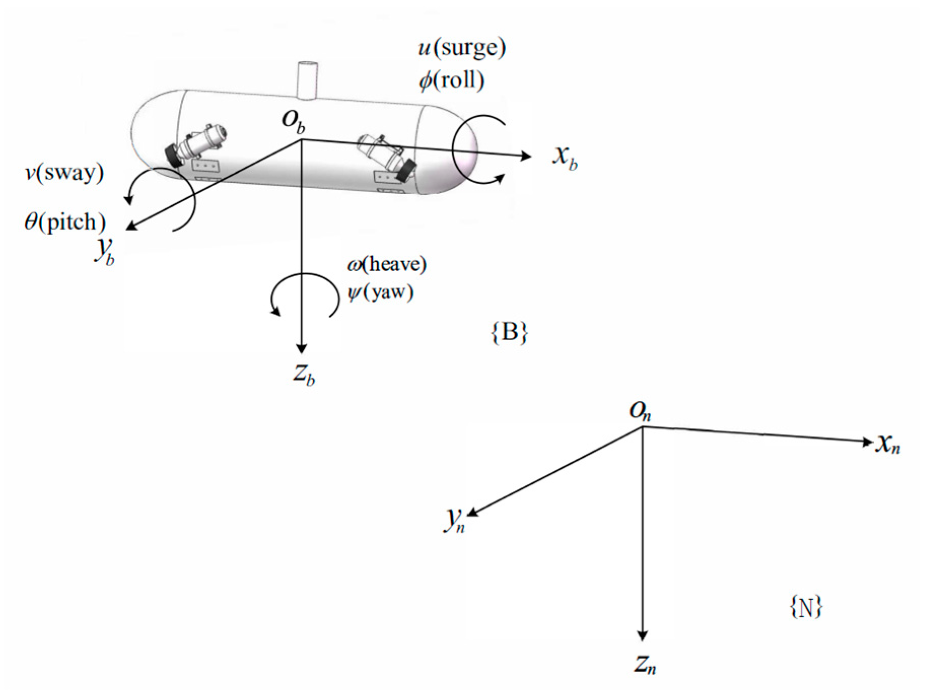
This paper investigates the three-dimensional trajectory tracking problem for a quadrotor-like autonomous underwater vehicle (QAUV), illustrated in Figure 1. The QAUV, originally introduced in [34], is characterized by its distinctive X-shaped thruster configuration, referred to as the X-shape actuation system [35]. To formulate the tracking problem, two coordinate frames are defined: an inertial frame N = x n , y n , z n with origin o n , and a body-fixed frame B = x b , y b , z b with origin o b , as shown in Figure 2. These frames are used to describe the vehicle’s kinematic and dynamic models in the subsequent sections.
The kinematic model of the vehicle in three-dimensional space can be written as
η ˙ 1 η ˙ 2 = J 1 η 0 3 × 3 0 3 × 3 J 2 η ν ˙ 1 ν ˙ 2
where η 1 = x , y , z T is the inertial coordinate of the vehicle, and η 2 = ϕ , θ , ψ T is the orientation of B with respect to N . ν 1 = u , v , w T with u , v , and w denoting the linear velocities in the surge, sway, and heave directions, respectively. ν 2 = p , q , r T with p , q , r being the angular velocities in the roll, pitch, and yaw directions, respectively. The linear velocity transformation matrix J 1 η and angular velocity transformation matrix J 2 η are given as follows [38]
J 1 η = c ψ c θ c ψ s θ s ϕ s ψ c θ c ψ s θ c ϕ + s ψ s θ s ψ c θ s ψ s θ s ϕ + c ψ c θ s ψ s θ c ϕ c ψ s θ s θ c θ s ϕ c θ c ϕ , J 2 η = 1 s ϕ t θ c ϕ t θ 0 c ϕ s ϕ 0 s ϕ / c θ c ϕ / c θ
where the abbreviations c j = cos j , s j = sin j , and t j = tan j are used for the sake of brevity.
The dynamic model of the vehicle in three-dimension space can be written as
M ν ˙ = N η , ν + Γ = C ν ν D ν ν g η + Γ
where ν = ν 1 T , ν 2 T T . M is the system inertia matrix. C ν denotes the Coriolis-centripetal matrix satisfying the skew-symmetric property such that ν T C ν ν 0 . D ν is the damping matrix. g η is the force and moment vector caused by gravitation and buoyancy (i.e., the restoring moment in the roll and pitch directions), Γ = τ 1 , 0 , τ 3 , τ 4 , τ 5 , τ 6 T is the control input. See Appendix A for the detailed element form of (3).
Define the actuator vector as F = F 1 , F 2 , F 3 , F 4 T , where F i denotes the force produced by the i-th actuator of the vehicle. The relation between Γ and F can be expressed as Γ = B F , where B is the force allocation matrix, and its parameterized form is
B = c α c α c α c α 0 0 0 0 s α s α s α s α y 0 s α y 0 s α y 0 s α y 0 s α x 0 s α x 0 s α x 0 s α x 0 s α y 0 c α y 0 c α y 0 c α y 0 c α
where x 0 , y 0 , and α are the actuator position and angle parameters, of which the detailed explanation about the matrix B can be found in [39]. From the column of (4) one can see that each actuator will produce forces and moments in the surge, heave, roll, pitch, and yaw directions such that the actuation system is strong coupled. In order to decouple the actuation system, a force transformation matrix T satisfying
T = 1 4 c α 1 4 s α 1 4 y 0 s α 1 4 x 0 s α 1 4 c α 1 4 s α 1 4 y 0 s α 1 4 x 0 s α 1 4 c α 1 4 s α 1 4 y 0 s α 1 4 x 0 s α 1 4 c α 1 4 c α 1 4 y 0 s α 1 4 x 0 s α
is introduced such that F = T F , where F = F 1 , F 2 , F 3 , F 4 T . Then one has
Γ = B F = B T F = F 1 , 0 , F 2 , F 3 , F 4 , β F 4 T
where β = y 0 / x 0   t α is the only coupling term in the actuation system. The controller design for actuator force F can be transformed into the design for F , which is more easily achieved.
In practice, due to the actuator’s physical limitations, the control inputs are subject to saturation and can be described as follows:
F i = F i m a x if   F i c > F i m a x F i c if   F i m i n F i c F i m a x , i 1 , 2 , 3 , 4 F i m i n if   F i c < F i m i n
where F i m a x and F i m i n denote the maximum and the minimum values of the i-th actuator, respectively. F c = F 1 c , F 2 c , F 3 c , F 4 c T is the commanded control input.
Remark 1.
As seen in (6), The QAUV has three independent control inputs in the surge, heave, and roll directions and the coupling input with a scale constant  β  in the pitch and yaw directions. It lacks of the control input in the sway direction. And that why we call it underactuated. Furthermore, the X-shaped actuator system can provide forces/torques in the direction of surge, heave, and roll by the resolution and composition of four actuators. It makes the QAUV more maneuverable in contrast to traditional AUVs.
Remark 2.
The parameter  β  is an inherent coupling term between the pitch and yaw directions in the actuation system of the vehicle, which means that yaw motion of the vehicle will inevitably leads to pitch motion. In practice, too rapid yaw motion should be avoided such that the additional pitch motion can be compensated by the restoring moment  B G z ¯   W sin θ  (see Appendix A, Equation (A1)) of the vehicle to avoid singularity (i.e.,  θ = π / 2 ).
Before controller design, some assumptions are given as follows:
Assumption 1.
The desired trajectory  x d , y d , z d  is chosen to guarantee that  x d , x ˙ d , x ¨ d , y d , y ˙ d , y ¨ d , z d , z ˙ d , z ¨ d  are bounded.
Assumption 2.
The pitch angle  θ  of the QAUV satisfies  | θ | < π / 2 .

2.2. Control Objective

Let η 1 d = x d , y d , z d T   be the desired position with ψ d the desired yaw angle. Then, the objective of the paper is to design a controller law F c that forces the vehicle to converge to the desired trajectory and achieve the yaw angle tracking such that η 1 η 1 d and ψ ψ d as t , while guaranteeing the uniform ultimate boundedness of all the closed-loop system and preventing the actuator saturation violation.

3. Controller Design

This part gives a detailed description for controller design based on the backstepping technique. Due to the fact that the actuation system of the vehicle can provide the independent roll moment, the controller design is divided into two parts: roll controller ( F 3 ) and position controller ( F 1 , F 2 , F 4 ). Each controller consists of two stages as follows. The virtual control laws are developed at the first stage. And the DSC technique is used to overcome the problem of explosion of complexity in backstepping. At the second stage, the actual dynamic control laws are designed. The anti-windup system is employed to handle actuator saturation. The stability of the closed-loop system is analyzed by using Lyapunov theory in the next section. For ease of understanding, the control block is illustrated in Figure 3.
As illustrated in Figure 3, two kinematic controller generates desired velocity signals u d ,   r d ,   w d ,   p d   based on position/orientation errors, and the dynamic controller computes the actual actuator forces required to achieve those desired velocities. First-order filters are used to avoid differentiation explosion in the backstepping design. An anti-windup system compensates for actuator saturation effects.

3.1. Roll Controller

In the part, the roll controller F 3 is designed to make the roll angle converge to a neighbor of the zero. According to the kinematic model (1), the roll dynamic is
ϕ ˙ = p + s ϕ t θ q + c ϕ t θ r .
Firstly, the virtual control law p d is designed as follows:
p d = k ϕ ϕ s ϕ t θ q c ϕ t θ r
where k ϕ > 0 is a positive constant. Then, the virtual control law p d is passed through a first-order filter:
κ p p ˙ f + p f = p d , p f 0 = p d 0
where κ p > 0 is the time constant. This filter means that p ˙ d is easily captured by p ˙ f   such that the resulting backstepping controller law is simple and easy to implement in practice.
Define the roll angular error as p e = p p f . It follows from (3) and (6) that we have
m 4 p ˙ e = m 4 p ˙ m 4 p ˙ f = n 4 η , ν m 4 p ˙ f + F 3
where n i η , ν denotes the i-th row of N η , ν in (3). Then, F 3 is designed as
F 3 = n 4 η , ν + m 4 p ˙ f k p p e ϕ
where k p > 0 is a positive constant.

3.2. Position Controller

In this part, the controller law F 1 , F 2 , F 4 is designed to make the vehicle’s position η 1 converge to the neighbor of η 1 d . Firstly, with the hand position method, the position error ε and a new vector z 1 are designed as follows:
ε = J 1 ( η ) 1 η 1 d η 1 sgn δ , z 1 = ε ρ
where z 1 = z 11 , z 12 , z 13 T , ρ = δ , 0 , 0 T , and δ 0 holds.
Firstly, differentiating z 1 with respect to time yields
z ˙ 1 = S ν 2 z 1 S ν 2 ρ sgn δ ν 1 + sgn δ J 1 ( η ) 1 η ˙ 1 d = S ν 2 z 1 + P u r w 0 v sgn δ q δ + sgn δ J 1 ( η ) 1 η ˙ 1 d
where
S ν 2 = 0 r q r 0 p q p 0 , P = sgn δ 0 0 0 δ 0 0 0 sgn δ
The virtual control law u d , r d , w d T is proposed as
u d r d w d = P 1 K 1 z 1 + 0 v sgn δ q δ sgn δ J 1 ( η ) 1 η ˙ 1 d
where K 1 R 3 × 3 is a positive definite matrix. Similarly, the virtual control law u d , r d , w d T is also passed through three first-order filters:
κ u u ˙ f + u f = u d , u f 0 = u d 0 , κ r r ˙ f + r f = r d , r f 0 = r d 0 , κ w w ˙ f + w f = w d , w f 0 = w d 0 ,
where κ u > 0 ,   κ r > 0 , and κ w > 0 are the time constants.
Remark 3.
In practice, to avoid that the resulting virtual control law is too large due to the large value of  z 1 , we introduce an arctan function to restrict the value of the virtual control law. i.e., the term  K 1 z 1  is replaced by  K 1   a r c t a n z 1 . Some comparative simulation results illustrate its performance.
Define a new error vector as z 2 = u e , r e , w e T = u u f , r r f , w w f T and an inertial matrix as M z 2 = diag m 1 , m 6 , m 3 . It follows from (3) and (6) that we have
M z 2 z ˙ 2 = n 1 η , ν n 6 η , ν n 3 η , ν m 1 u ˙ f m 6 r ˙ f m 3 w ˙ f + F 1 β F 4 F 2 .
Then the controller law F 1 , F 2 , F 4 is designed as
F 1 β F 4 F 2 = n 1 η , ν n 6 η , ν n 3 η , ν + m 1 u ˙ f m 6 r ˙ f m 3 w ˙ f K 2 z 2 P z 1
where K 2 R 3 × 3 is a positive definite matrix.

3.3. Actuator Saturation Handling

To deal with actuator saturation (7), an anti-windup system is introduced as follows
ξ ˙ = K ξ ξ z ξ T B ξ Δ F + 0.5 Δ F T Δ F ξ 2 ξ + Δ F if   ξ σ , 0 4 × 1 if   ξ < σ ,
where ξ R 4 is the state vector of the anti-windup system, Δ F = F F c is the deviation between the actual actuator output F   and the commanded control law F c . K ξ R 3 × 3 is a positive definite matrix, and σ > 0 is a small constant. z ξ   and B ξ are designed as z ξ = u e , w e , p e , r e T and B ξ = B 1 T , B 3 T , B 4 T , B 6 T T with B i being the i -th row of B .
According to the above controller design including roll controller (12), position controller (19), and actuator saturation handing procedures (20), we design the resulting control law as follows:
F c = T F + K s ξ
where K s R 4 × 4 is a positive definite matrix.
Remark 4.
It is noted that non-linearities play an essential role in the controller’s efficiency and accuracy. In this paper, the system nonlinearities are addressed in the following three ways: (1) The core of the proposed controller is based on backstepping technique. At each step, it treats the subsequent subsystem’s state as a “virtual control” and actively cancels out the inherent nonlinearities; (2) A well-known weakness of standard backstepping is the “explosion of complexity” caused by the repeated differentiation of virtual control laws, which depends heavily on all nonlinear system states. In this paper, we integrate the Dynamic Surface Control (DSC) technique to over explosion of complexity problem. (3) The physical limitation of actuators introduces a critical and damaging nonlinearity. The proposed controller employs an auxiliary dynamic system (20) to handle input saturation nonlinearity.
Remark 5.
In contrast to SMC [21,22,23], which often suffers from chattering due to high-frequency control switching, the proposed controller generates continuous and smooth control signals, thereby enhancing actuator longevity and operational reliability. In contrast to MPC [40], which relies on computationally demanding online optimization, the proposed controller is formulated as a closed-form feedback law. This significantly reduces computational burden and facilitates real-time implementation on embedded systems with limited resources.

4. Stability Analysis

This section analyzes the stability of the control system by Lyapunov theory and phase plane methods. The analyses are organized as follows. First, it will be shown that all signals in the subsystem Σ ϕ , p e , z 1 , z 2 described by (8), (11), (13), and (18) are uniformly ultimately bounded. The analysis that v and q are uniformly ultimately bounded will follow. At last, we conclude the convergence of ψ by phase plane analyses. For ease of readability, Figure 4 provides a chart of system stability analyses.

4.1. The Convergence of Σ ϕ , p e , z 1 , z 2

In order to analyze the convergence of the subsystem Σ ϕ , p e , z 1 , z 2 , a Lyapunov function candidate is selected as
V = 1 2 ϕ 2 + 1 2 m 4 p e 2 + 1 2 z 1 T z 1 + 1 2 z 2 T M z 2 z 2 + 1 2 ζ T ζ + 1 2 ξ T ξ
where ζ is the first-order filter output error vector with the following definition
ζ = ζ 1 , ζ 2 , ζ 3 , ζ 4 T = u f u d , w f w d , p f p d , r f r d T .
The time derivative of V is
V ˙ = ϕ ϕ ˙ + m 4 p e p ˙ e + z 1 T z ˙ 1 + z 2 T M z 2 z ˙ 2 + ζ T ζ ˙ + ξ T ξ ˙ .
According to (8), (9), (14), (16), (23), p e = p p f ,   z 2 = u u f , r r f , w w f T and Young’s inequality, we have
ϕ ϕ ˙ + z 1 T z ˙ 1 = k ϕ ϕ 2 + ϕ p e + ϕ ζ 3 z 1 T K 1 z 1 + z 1 T P z 2 + z 1 T ζ 1 , ζ 4 , ζ 2 T k ϕ ϕ 2 z 1 T K 1 z 1 + 1 2 ϕ 2 + 1 2 z 1 T z 1 + 1 2 ζ T ζ + ϕ p e + z 1 T P z 2
In view of (12), (19), (21), F c = F + Δ F and Young’s inequality, we have
m 4 p e p ˙ e + z 2 T M z 2 z ˙ 2 = k p p e 2 z 2 T K 2 z 2 + z ξ T B ξ K s ξ + z ξ T B ξ Δ F ϕ p e z 2 T P z 1 k p p e 2 z 2 T K 2 z 2 + 1 2 z ξ T z ξ + 1 2 ξ T K s T B ξ T B ξ K s ξ + z ξ T B ξ Δ F ϕ p e z 2 T P z 1 .
Using (10), (17) and (23), we have
ζ T ζ ˙ = ζ T ζ 1 κ u u ˙ d , ζ 2 κ w w ˙ d , ζ 3 κ p p ˙ d , ζ 4 κ r r ˙ d T ζ T K ζ ζ + ζ Q ϕ , p e , z 1 , z 2 , ζ ζ T K ζ ζ + 1 2 ζ 2 Q ϕ , p e , z 1 , z 2 , ζ 2 + 1 2
where K ζ = diag 1 / κ u , 1 / κ w , 1 / κ p , 1 / κ r and Q ϕ , p e , z 1 , z 2 , ζ is a continuous vector function.
According to the anti-windup system ξ in (20), the stability analyses are given in the following two cases.
(1) When ξ σ , in view of (20) and Young’s inequality we have
ξ T ξ ˙ = ξ T K ξ ξ z ξ T B ξ Δ F 1 2 Δ F T Δ F + ξ T Δ F ξ T K ξ ξ z ξ T B ξ Δ F + 1 2 ξ T ξ .
Substituting (25)–(28) into (24) yields
V ˙ k ϕ ϕ 2 z 1 T K 1 z 1 + 1 2 ϕ 2 + 1 2 z 1 T z 1 + 1 2 ζ T ζ + ϕ p e + z 1 T P z 2 k p p e 2 z 2 T K 2 z 2 + 1 2 z ξ T z ξ + 1 2 ξ T K s T B ξ T B ξ K s ξ + z ξ T B ξ Δ F ϕ p e z 2 T P z 1 ζ T K ζ ζ + 1 2 ζ 2 Q ϕ , p e , z 1 , z 2 , ζ 2 + 1 2 ξ T K ξ ξ z ξ T B ξ Δ F + 1 2 ξ T ξ k ϕ 1 2 ϕ 2 k p 1 2 p e 2 λ m i n K 1 1 2 z 1 T z 1 λ m i n K 2 1 2 z 2 T z 2 λ m i n K ξ 1 2 K s T B ξ T B ξ K s 1 2 ξ T ξ λ m i n K ζ 1 2 ζ T ζ + 1 2 ζ 2 Q ϕ , p e , z 1 , z 2 , ζ 2 + 1 2
where λ m i n is the minimum eigenvalue of a matrix. Consider a compact set
Π = ϕ , p e , z 1 , z 2 , ξ , ζ R 16 : V Q 0 , Q 0 > 0 .
Then, we have Q ϕ , p e , z 1 , z 2 , ζ < Q M on Π due to the continuity of Q ϕ , p e , z 1 , z 2 , ζ , where Q M > 0 . Designing K ζ as λ m i n K ζ = 1 / 2 + Q M 2 / 2 + μ * with μ * > 0 , we have
V ˙ k ϕ 1 2 ϕ 2 k p 1 2 p e 2 λ m i n K 1 1 2 z 1 T z 1 λ m i n K 2 1 2 z 2 T z 2 λ m i n K ξ 1 2 K s T B ξ T B ξ K s 1 2 ξ T ξ μ * + Q M 2 2 ζ T ζ + Q ϕ , p e , z 1 , z 2 , ζ 2 Q M 2 Q M 2 ζ 2 2 + 1 2 2 μ 1 V + C 1 1 Q ϕ , p e , z 1 , z 2 , ζ 2 Q M 2 Q M 2 ζ 2 2
where C 1 = 1 / 2 and
μ 1 = m i n k ϕ 1 2 , k p 1 2 m 4 , λ m i n K 1 1 2 , λ m i n K 2 1 2 λ m a x M z 2 , μ * , λ m i n K ξ 1 2 K s T B ξ T B ξ K s 1 2 .
(2) When ξ < σ , in view of (20) and Young’s inequality we have
ξ T ξ ˙ = 0 1 2 ξ T K s T B ξ T B ξ K s ξ = 1 2 ξ T K s T B ξ T B ξ K s ξ + ξ T K s T B ξ T B ξ K s ξ < 1 2 ξ T K s T B ξ T B ξ K s ξ + σ 2 K s T B ξ T B ξ K s z ξ T B ξ Δ F 1 2 z ξ T z ξ + 1 2 B ξ Δ F 2
Substituting (25), (26), (27) and (33) into (24) yields
V ˙ k ϕ ϕ 2 z 1 T K 1 z 1 + 1 2 ϕ 2 + 1 2 z 1 T z 1 + 1 2 ζ T ζ k p p e 2 z 2 T K 2 z 2 + 1 2 z ξ T z ξ 1 2 ξ T K s T B ξ T B ξ K s ξ + σ 2 K s T B ξ T B ξ K s + 1 2 z ξ T z ξ + 1 2 B ξ Δ F 2 ζ T K ζ ζ + 1 2 ζ 2 Q ϕ , p e , z 1 , z 2 , ζ 2 + 1 2 k ϕ 1 2 ϕ 2 k p 1 p e 2 λ m i n K 1 1 2 z 1 T z 1 λ m i n K 2 1 z 2 T z 2 1 2 λ m i n K s T B ξ T B ξ K s ξ T ξ λ m i n K ζ 1 2 ζ T ζ + σ 2 K s T B ξ T B ξ K s + 1 2 ζ 2 Q ϕ , p e , z 1 , z 2 , ζ 2 + 1 2 + 1 2 B ξ Δ F 2 .
In view of λ m i n K ζ = 1 / 2 + Q M 2 / 2 + μ * with μ * > 0 , we have
V ˙ k ϕ 1 2 ϕ 2 k p 1 p e 2 λ m i n K 1 1 2 z 1 T z 1 λ m i n K 2 1 z 2 T z 2 1 2 λ m i n K s T B ξ T B ξ K s ξ T ξ μ * + Q M 2 2 ζ T ζ + σ 2 K s T B ξ T B ξ K s + Q ϕ , p e , z 1 , z 2 , ζ 2 Q M 2 Q M 2 ζ 2 2 + 1 2 + 1 2 B ξ Δ F 2 2 μ 2 V + C 2 1 Q ϕ , p e , z 1 , z 2 , ζ 2 Q M 2 Q M 2 ζ 2 2
where C 2 = 1 / 2 + 1 / 2 B ξ Δ F 2 + σ 2 K s T B ξ T B ξ K s and
μ 2 = min k ϕ 1 2 , k p 1 m 4 , λ m i n K 1 1 2 , λ m i n K 2 1 λ m a x M z 2 , μ * , 1 2 λ m i n K s T B ξ T B ξ K s
It follows from (31) and (35) that we have
V ˙ 2 μ V + C 1 Q ϕ , p e , z 1 , z 2 , ζ 2 Q M 2 Q M 2 ζ 2 2 ,
where μ = min μ 1 , μ 2 and C = max C 1 , C 2 with the controller parameters k ϕ ,   k p ,   K 1 ,   K 2 ,   K s , and K ξ satisfying
k ϕ > 1 2 , k p > 1 , λ m i n K 1 > 1 2 , λ m i n K 2 > 1 , λ m i n K ξ 1 2 K s T B ξ T B ξ K s > 1 2 , λ m i n K ζ = 1 2 + Q M 2 2 + μ * , μ * > 0 , μ > C 2 Q 0 .
For the control law (21) with the parameters satisfying (38), we have the following lemma.
Lemma 1.
The compact set  Π = { ϕ , p e , z 1 , z 2 , ξ , ζ R 16 : V Q 0 ,   Q 0 > 0  is an invariant set.
Proof. 
On V ϕ , p e , z 1 , z 2 , ξ , ζ = Q 0 , there exists Q ϕ , p e , z 1 , z 2 , ζ < Q M . Then we have V ˙ 2 μ Q 0 + C from (37). Since μ > C / 2 Q 0 holds, V ˙ < 0 is satisfied on V ϕ , p e , z 1 , z 2 , ξ , ζ = Q 0 . Thus, Π is an invariant set. This ends the proof. □
The above Lemma means that if V 0 Q 0 , then V t Q 0 for all t > 0 . Thus, Q ϕ , p e , z 1 , z 2 , ζ < Q M holds for all V t Q 0 , which means that
V ˙ 2 μ V + C
holds for all V t Q 0 . Solving (39), we have
0 V C 2 μ + V 0 C 2 μ e 2 μ t .
Thus, V is uniformly ultimately bounded. In view of (22), we know that ϕ ,   p e ,   z 1 ,   z 2 ,   ξ , and ζ are uniformly ultimately bounded. Combining with (13), (23), we have η 1 ,   ϕ ,   u ,   w ,   p ,   and r are uniformly ultimately bounded. Furthermore, in the light of (22) and (40), we have
ϕ , z 1 T C μ + 2 V 0 C 2 μ e 2 μ t .
It is obviously seen that for all V t Q 0 and any positive constant γ > C / μ , there exists a time constant T γ > 0 , such that ϕ , z 1 T < γ   f o r   a l l   t > T γ . Thus, ϕ , z 1 T settles with the set Ω 1 = ϕ , z 1 T R 4 : ϕ , z 1 T γ , which can be made arbitrarily small by appropriately selecting controller parameters such that (38) is satisfied. Hence, the vehicle can be maintained at the desired position η 1 d and the zero roll angle with arbitrarily small errors.

4.2. The Convergence of v and q

Define the following Lyapunov candidate function
V v q = 1 2 m 2 v 2 + 1 2 m 5 q 2
By using (3), the time derivative of V q can be written as
V ˙ v q = v m 1 u r + m 3 w p d 2 v + q m 1 m 3 u w m 4 m 6 p r d 5 q B G z ¯ W sin θ + F 4 m 3 w p m 1 u r v d 2 v 2 + F 4 m 1 m 3 u w m 4 m 6 p r B G z ¯ W sin θ q d 5 q 2 2 ϵ m m i n V v q 2 d m i n m m a x V v q ,
where m m i n = min m 2 , m 5 , m m a x = max m 2 , m 5 ,   d m i n = min d 2 , d 5 , and ϵ = max m 3 w p m 1 u r , F 4 m 1 m 3 u w m 4 m 6 p r B G z ¯ W s i n θ is bounded due to the fact that u ,   w ,   p ,   r are ultimately uniformly bounded.
Define the following compact set
Ω v q = v , q R 2 : V v q ϵ 2 m m a x 2 d m i n 2 m m i n .
If v , q Ω v q ,   V ˙ v q < 0 holds. All the solutions that start outside of the compact set Ω v q will enter this set, and remain inside the set for all future time. Therefore, v and q remain uniformly ultimately bounded.

4.3. The Convergence of ψ

In view of (1), we have
ψ ˙ = q s ϕ c θ + r c ϕ c θ .
When the vehicle achieves the trajectory tracking, we have r = r d . Substituting (16) into (45) yields
ψ ˙ = q s ϕ c θ sgn δ δ v c ψ s θ s ϕ s ψ c θ x ˙ d s ψ s θ s ϕ + c ψ c θ y ˙ d c θ s ϕ z ˙ d c ϕ c θ = s ϕ q c θ + c ϕ δ c θ c ψ s θ x ˙ d + s ψ s θ y ˙ d + c θ z ˙ d c ϕ δ v + s ψ x ˙ d c ψ y ˙ d .
As shown in (41), the roll angle ϕ of the vehicle will converge to zero with arbitrarily small errors, which means that s ϕ 0 and c ϕ 1 . Define κ = x ˙ d 2 + y ˙ d 2 + z ˙ d 2 , θ d and ψ d denote the desired pitch angle and yaw angle, respectively. Then we have
x ˙ d = κ c θ d c ψ d ,   y ˙ d = κ c θ d s ψ d , z ˙ d = κ s θ d .
Substituting (47) into (46) yields
ψ ˙ = κ δ s ψ c θ d c ψ d c ψ c θ d s ψ d + v κ = κ c θ d δ s ψ e + v κ c θ d
where ψ e = ψ ψ d . The time derivative of ψ e is given as
ψ ˙ e = κ c θ d δ s ψ e + v κ c θ d ψ ˙ d = κ c θ d δ s ψ e ε
where ε = v κ c θ d δ ψ ˙ d κ c θ d with ψ ˙ d being the first-order derivative of ψ . In practice, the desired pitch angle θ d of the vehicle satisfies π / 2 < θ d < π / 2 , which means that c θ d > 0 .
The equilibrium state of the system (49) is defined as ψ ¯ , then one gets
sin ψ ¯ e ε = 0
where ε 1 should be satisfied. Solving (50) yields
ψ ¯ e = ψ ¯ e 1 = arc sin ε + 2 k π ψ ¯ e 2 = arc sin ε + 2 k + 1 π ,   k Z .
In order to analyze the dynamic of ψ e , the phase plane ( ψ ˙ e ,   ψ e ) is plotted in Figure 5, where the blue arrows denote the moving direction of ψ e . As shown in Figure 5, ψ e tends to be close to ψ ¯ e 1 but far away from ψ ¯ e 2 . Here, we call ψ ¯ e 1 the stable equilibrium state and ψ ¯ e 2 the unstable equilibrium state. Thus, ψ e is uniformly ultimately bounded and will converge to ψ ¯ e 1 .
Remark 6.
In practice, the value of the sway velocity v for an underactuated vehicle is small. Furthermore, the control parameter  δ  defined in (13) is designed small enough such that  ε 0 , which means that  ψ ¯ e 1 2 k π , where  k Z . Hence, we conclude that  ψ  will converge to the neighbor of  ψ d .
Remark 7.
In a related research work [15], the author proposed a similar error definition (Equation (8) in [15]) as (13) but without the signum function. Such an error definition will lead to the trajectory tracking in the opposite direction if  δ < 0  (corresponding to the equilibrium state  ψ ¯ e 2 ), which is undesirable in practice. In this paper, the yaw dynamics is governed by Equation (48), where the presence of the term |δ| results from incorporating the signum function in Equation (13). This formulation ensures that the yaw dynamics remains unaffected by the sign of the parameter δ. As a result, the vehicle tracks the desired trajectory in the correct direction regardless of the sign of δ. This enhancement makes the proposed control law more general and practically applicable.
Synthesizing the analyses of the above three subsections, we have the following theorem.
Theorem 1.
Consider the kinematic model (1) and dynamic model (3) of the QAUV with actuator saturation (7) and the trajectory tracking control law (21) based on the backstepping technique employing the first-order filters (10) and (17), and the auxiliary dynamic system (20). For all  V Q 0  with  Q 0  being any positive constant, the roll-position error vector  ϕ , z 1 T  settles within  Ω 1 = { ϕ , z 1 T R 4 : ϕ , z 1 T γ ,   γ > C / μ } , which can be made arbitrarily small by appropriately selecting controller parameters such that (38) is satisfied. While all signals in the trajectory tracking closed-loop system are ultimately uniformly bounded.
Proof. 
It follows from the analysis of Section 4.1 that we have η 1 ,   ϕ ,   u ,   w ,   p , and r   are uniformly ultimately bounded and the roll-position error vector ϕ , z 1 T settles within Ω 1 = { ϕ , z 1 T R 4 : ϕ , z 1 T γ ,   γ > C / μ } , which can be made arbitrarily small if (38) is satisfied. Combining the results from Section 4.2 and Section 4.3, we conclude that all signals in the closed-loop system are ultimately uniformly bounded and the vehicle can achieve the trajectory tracking with arbitrarily small position error, and keep the same yaw direction as the desired trajectory. This ends the proof. □

5. Simulation Results

In this part, simulation results are presented to validate the performance of the proposed control law. Matlab Simulation 2017b software is applied for system modeling and controller achievements. The desired spiral line is given below:
x d y d z d = 40 cos 0.01 π t 40 sin 0.01 π t 0.1 t m .
Unlike a simple circle or straight line, the spiral line (52) introduces continuously time-varying linear and angular velocities. This is a more rigorous test of the controller’s ability to track dynamic commands and manage the system’s coupled dynamics than a constant-velocity trajectory. On the other hand, For our underactuated vehicle, the spiral path is particularly challenging as it requires continuous and coordinated management of surge, heave, and yaw motions to maintain the correct heading and position.
The vehicle and controller parameters are summarized at Table 1. In order to check the performance of the DSC technique and the arctan function (mentioned in Remark 3), three comparative control laws are listed as follows:
Type1: The proposed controller (21) with DSC techniques but without the arctan function;
Type2: The proposed controller without DSC techniques and the arctan function;
Type3: The proposed controller with both DSC techniques and the arctan function.
Figure 6 displays the three-dimension trajectory of QAUV when tracking a spiral desired trajectory over the course of 600 s by using the proposed controller (21).
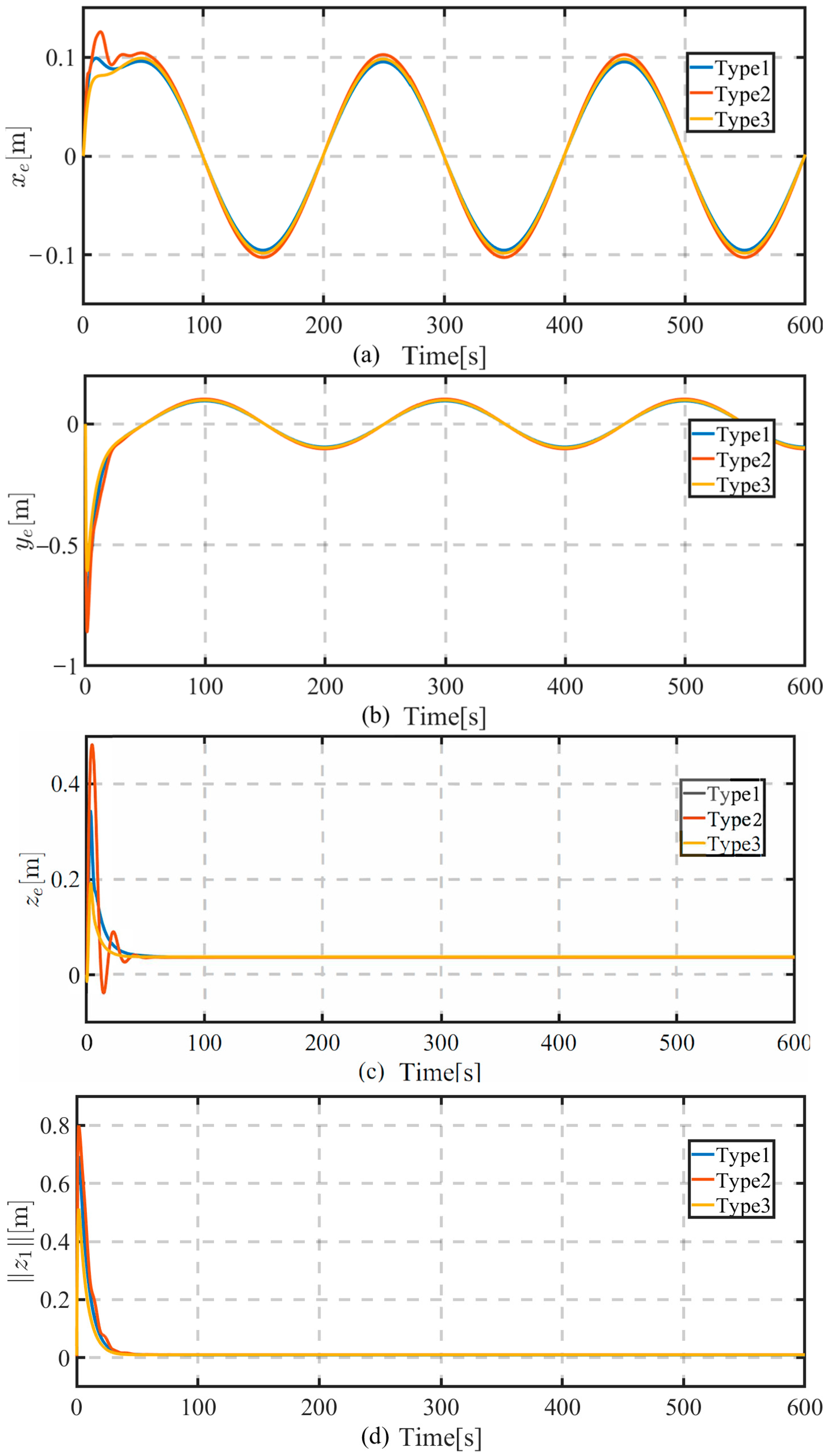
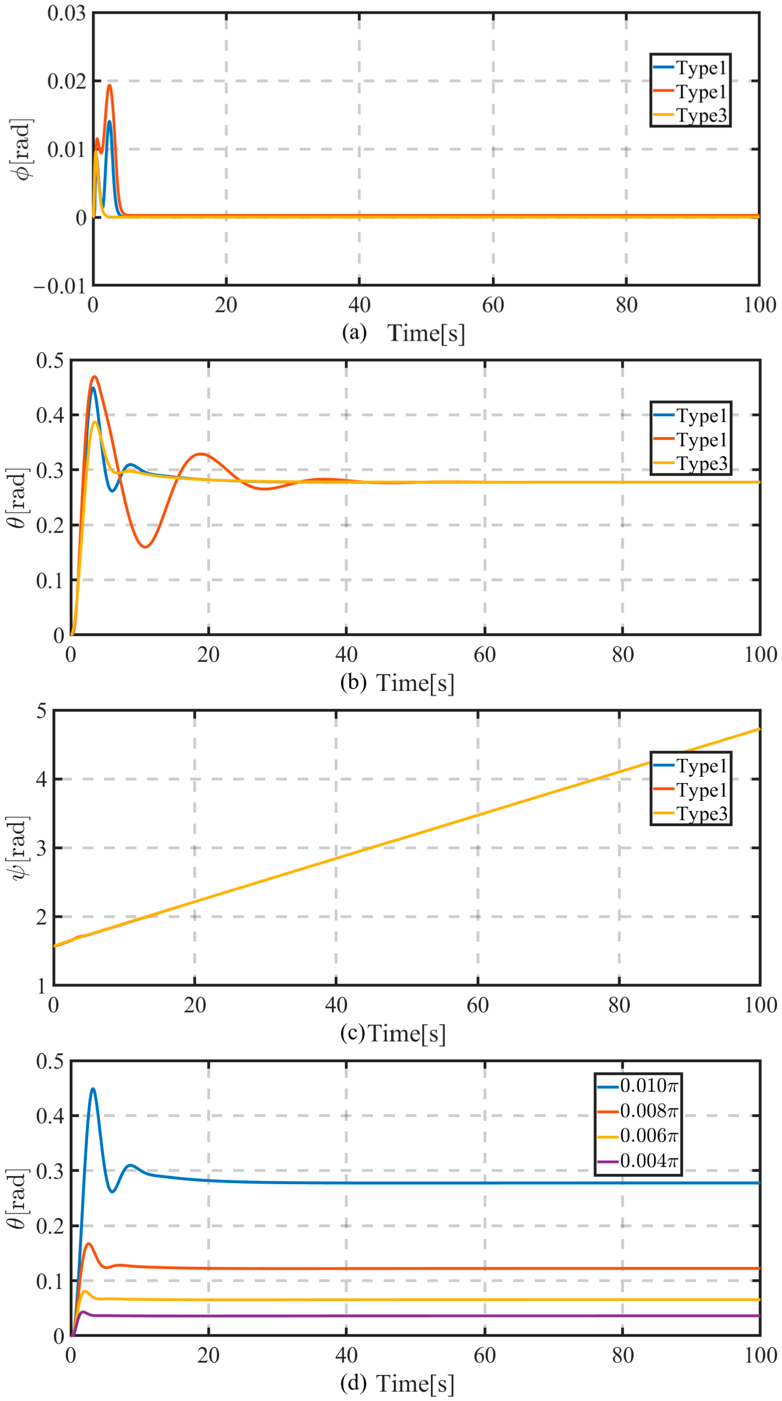
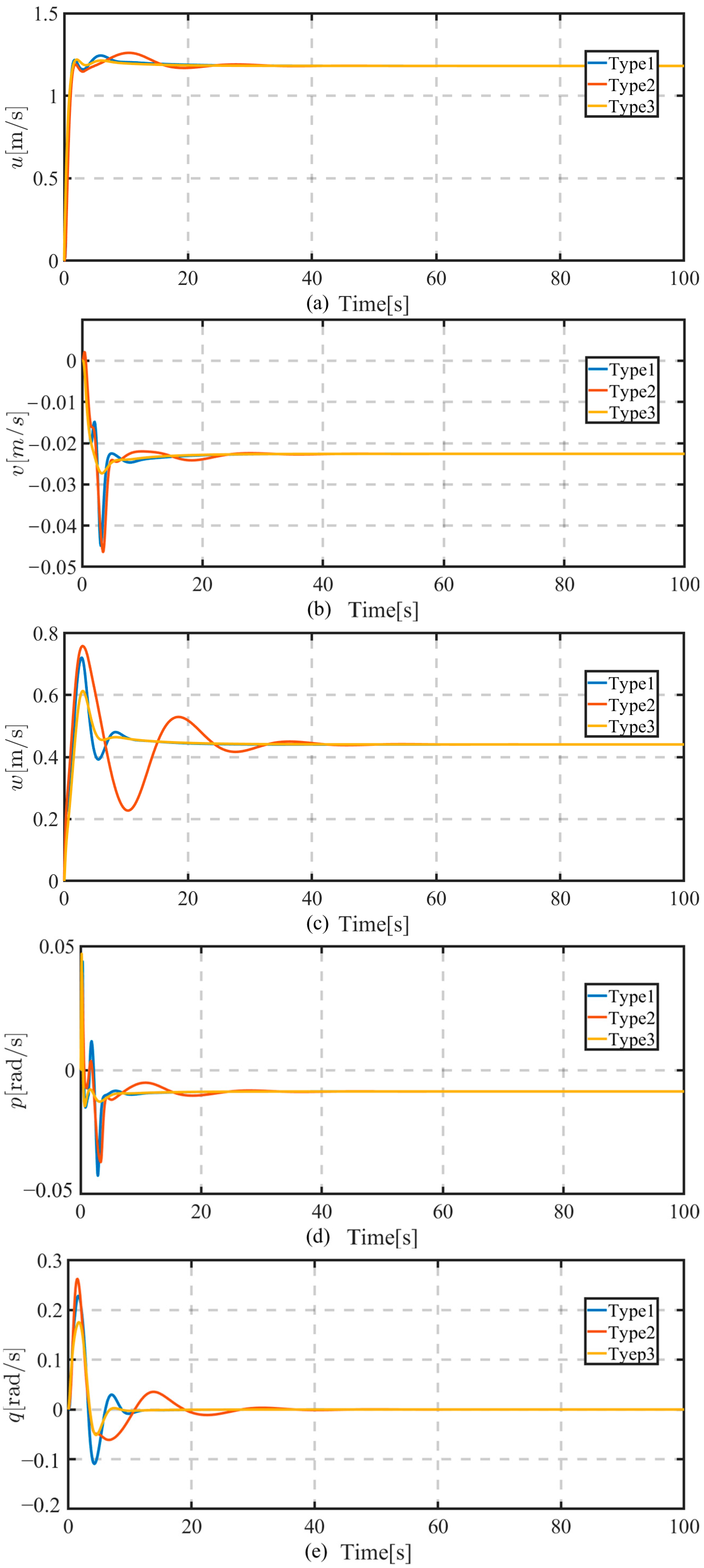
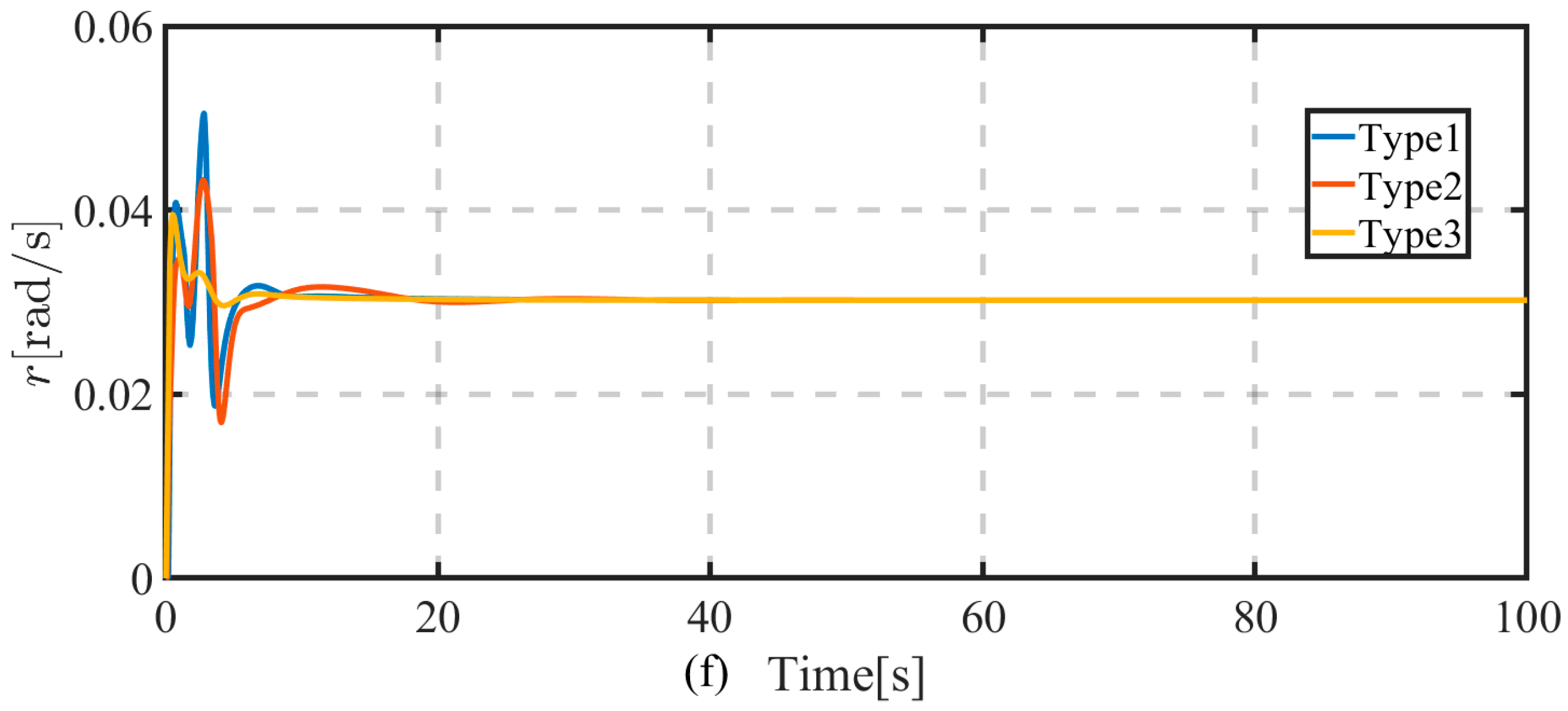
Figure 7 shows the time evolution of the positive error x e , y e , z e and the norm of the vector z 1 . It is observed that Type3 controller performs better with respect to the dynamic process and error peak, then Type1 and finally Type2. A comparison of the maximum error norms in Table 2 reveals the superior performance of Controller Type 3. It is the most effective in minimizing trajectory tracking errors, showing a distinct advantage over Type 1 and Type 2 in the y and z directions. Figure 8a–c depict the time evolution of the vehicle’s attitude ( ϕ ,   θ ,   ψ ) respectively. From Figure 8a,b one can see that Type3 controller exhibits better control performance with respect to the converge time of the roll and pitch angles, then Type1 and finally Type2. The time evolution of the vehicle’s velocity and controller inputs with respect to three different controllers are shown in Figure 9 and Figure 10, respectively. It is obvious that Type3 performs better considering the above two aspects. Furthermore, as shown in Figure 10a–c, the actuator outputs are within the corresponding saturation values by virtue of the anti-windup system (20).
As shown in Remark 2, there exists an inherent coupling parameter β between the pitch motion and yaw motion of the vehicle. That means that the yaw motion of the vehicle will inevitably lead to pitch motion. Figure 8d illustrates the time evolution of the pitch angle of the vehicle with respect to four different trajectories with the angular frequency (proportional to the yaw angular velocity) being 0.004 π ,   0.006 π ,   0.008 π , and 0.01 π , respectively. One can easily see that the faster the yaw angular velocity of the vehicle is, the larger the resulting pitch angle is. Therefore, too rapid yaw motion should be avoided as mentioned in Remark 2.
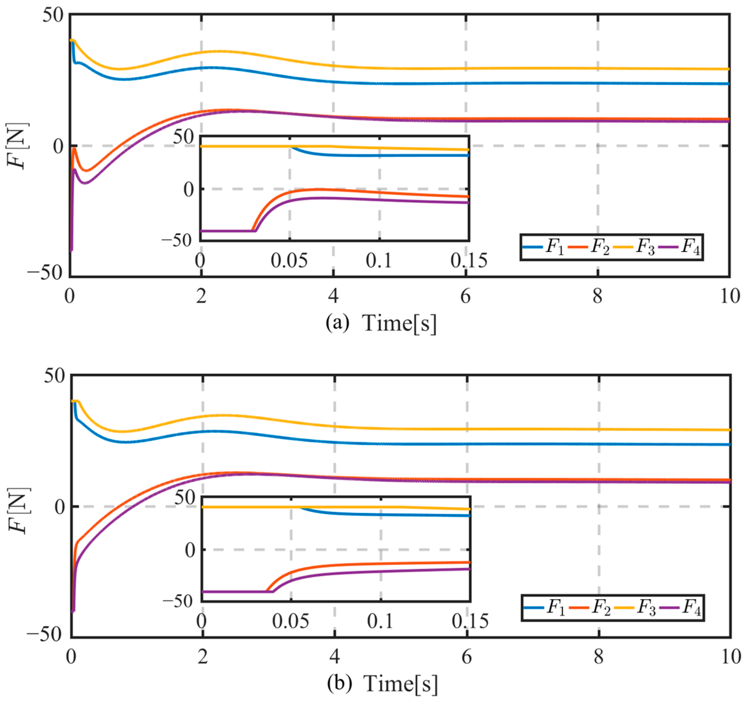
Figure 11 shows the time evolution of the yaw angle and yaw angle error by the proposed controller in [15]. The controller design is based on an error definition z 1 = J 1 η 1 η 1 d η 1 ρ , where the related notations are same as (13). It is shown from Figure 11b that if δ > 0 , the yaw angle ψ keeps the same direction as the desired trajectory and the yaw angle error ψ e converges to 2 k π . Alternately, if δ < 0 , the yaw angle ψ keeps the opposite direction to the desired trajectory and the yaw angle error ψ e converges to 2 k + 1 π . In this context, the yaw direction is affected by the signum of δ ,   which is not suitable for practical applications. In this paper, we define a new z 1 = J 1 ( η ) 1 η 1 d η 1 sgn δ ρ by adding a signum function sgn δ . Such the construction guarantees the actual trajectory of the vehicle keeps the same direction as the desired one whatever δ ’s signum is. In this sense, the proposed control law is more practical. Figure 12 displays the time evolution of control inputs F with the anti-windup system and without the anti-windup system. It can be observed that the control inputs F with the anti-windup system can far away from the saturation value earlier than those without the anti-windup system. However, it should be noted that this effect is rather limited.

6. Conclusions

This paper has addressed the complex problem of three-dimensional trajectory tracking for an underactuated quadrotor-like autonomous underwater vehicle (QAUV) subject to actuator saturation. The proposed solution integrates a modified hand-position method with a signum function, dynamic surface control (DSC), and an anti-windup auxiliary system. The primary strength of the designed controller lies in its comprehensive handling of key practical challenges. The novel error vector formulation guarantees that the vehicle’s yaw direction remains aligned with the desired trajectory, irrespective of the hand-position parameter δ, overcoming a critical limitation of traditional methods. The use of the DSC technique successfully circumvents the “explosion of complexity” inherent in standard backstepping, resulting in a controller that is not only theoretically sound but also computationally efficient and readily implementable. Furthermore, the integrated anti-windup mechanism ensures stable performance under realistic actuator constraints, a vital requirement for real-world deployment. However, the controller’s performance is subject to certain requirements and limitations. The stability guarantees rely on the accurate knowledge of the vehicle’s hydrodynamic parameters, and the controller’s performance in the presence of significant model inaccuracies or unmodeled external disturbances, such as strong, time-varying ocean currents, requires further investigation. Additionally, the theoretical and simulation-based validation, while comprehensive, must be considered a preliminary step. The ultimate validation of the controller’s practicality hinges on its implementation on a physical platform in a challenging marine environment.
It should be noted that the work presented in this paper focuses on establishing a proof-of-concept and demonstrating the novel theoretical and performance advantages of the method in a controlled simulation environment. The insights gained are directly relevant for future applied research and ultimately pave the way for market implementation, which would involve addressing additional challenges such as hardware integration, cost reduction, and extensive real-world testing. Future work will focus on enhancing the controller’s robustness through adaptive laws or ocean current observers to handle model uncertainties and environmental forces [41,42]. Experimental validation using a prototype QAUV will be the critical next step to transitioning this theoretical contribution into a practical solution for underwater operations.

Author Contributions

Conceptualization, C.C. and X.H.; methodology, Y.H.; software, L.K.; validation, C.C.; formal analysis, Y.O.; investigation, P.X. and Y.O.; resources, L.K.; data curation, X.H.; writing—original draft preparation, C.C. and L.K.; writing—review and editing, P.X. and L.K.; visualization, Y.O.; supervision, Y.H.; project administration, P.X.; funding acquisition, P.X. and Y.H. All authors have read and agreed to the published version of the manuscript.

Funding

This research was funded in part by the National Key Research and Development Program of China under grant number 2022YFC2807603, in part by the National Natural Science Foundation of China under grant number 62503353, 62403193 and 12202253, in part by the Science and Technology Innovation Program of Hunan Province under Grant 2024RC9015, and in part by Research and Development of Key Technologies for New Power System Sources and Storage under Extreme Conditions and Simulation Test Platform under grant number SXEIRI-ZDZD-2024002.

Data Availability Statement

The data that support the findings of this study are available from the corresponding authors upon reasonable request.

Conflicts of Interest

Author Yang Ou was employed by the State Grid Shanxi Provincial Power Limited Company Yuncheng Power Supply Company. The remaining authors declare that the research was conducted in the absence of any commercial or financial relationships that could be construed as a potential conflict of interest.

Appendix A

The element form of the dynamic Equation (3) of the vehicle is given as follows
m 1 u ˙ = m 3 w q + m 2 v r d 1 u + τ 1 m 2 v ˙ = m 3 w p m 1 u r d 2 v m 3 w ˙ = m 2 v p + m 1 u q d 3 w + τ 3 m 4 p ˙ = m 3 m 2 v w m 6 m 5 q r d 4 p B G z ¯ W cos θ sin ϕ + τ 4 m 5 q ˙ = m 1 m 3 u w m 4 m 6 p r d 5 q B G z ¯ W sin θ + τ 5 m 6 r ˙ = m 2 m 1 u v m 5 m 4 p q d 6 r + τ 6
where m 1 = m X u ˙ ,   m 2 = m Y v ˙ , m 3 = m Z w ˙ , m 4 = I x K p ˙ , m 5 = I y M q ˙ , m 6 = I z N r ˙ , d 1 = X u , d 2 = Y v , d 3 = Z w , d 4 = K p , d 5 = M q , d 6 = N r . m is the mass of the vehicle and W is the buoyancy of the vehicle. I x ,   I y   a n d   I z are the moments in the roll, pitch, and yaw directions. B G z ¯ denotes the distance between center of gravity and center of buoyancy, and the other symbols, such as X u ˙ , are hydrodynamic parameters. More details can be found in [38].

References

  1. Peng, Z.; Wang, J.; Wang, D.; Han, Q. An overview of recent advances in coordinated control of multiple autonomous surface vehicles. IEEE Trans. Ind. Inform. 2021, 17, 732–745. [Google Scholar] [CrossRef]
  2. Zhang, B.; Ji, D.; Liu, S.; Zhu, X.; Xu, W. Autonomous Underwater Vehicle navigation: A review. Ocean Eng. 2023, 273, 113861. [Google Scholar] [CrossRef]
  3. Yin, L.; Yan, Z.; Tian, Q.; Li, H.; Xu, J. A novel robust algorithm for path planning of multiple autonomous underwater vehicles in the environment with ocean currents. Ocean Eng. 2024, 312, 119260. [Google Scholar] [CrossRef]
  4. Liu, G.; Chen, L.; Liu, K.; Luo, Y. A swarm of unmanned vehicles in the shallow ocean: A survey. Neurocomputing 2023, 532, 74–86. [Google Scholar] [CrossRef]
  5. Do, K.; Jiang, Z.; Pan, J. Universal controllers for stabilization and tracking of underactuated ships. Syst. Control Lett. 2002, 47, 299–317. [Google Scholar] [CrossRef]
  6. Zhong-Ping, J.; Nijmeijer, H. A recursive technique for tracking control of nonholonomic systems in chained form. IEEE Trans. Autom. Control 1999, 44, 265–279. [Google Scholar] [CrossRef]
  7. Samson, C. Control of chained systems application to path following and time-varying point-stabilization of mobile robots. IEEE Trans. Autom. Control 1995, 40, 64–77. [Google Scholar] [CrossRef]
  8. Guerrero, J.; Chemori, A.; Creuze, V.; Torres, J.; Campos, E. Saturated STA-based sliding-mode tracking control of AUVs: Design, stability analysis, and experiments. Ocean Eng. 2024, 301, 117520. [Google Scholar] [CrossRef]
  9. Li, B.; Gao, X.; Huang, H.; Yang, H. Improved adaptive twisting sliding mode control for trajectory tracking of an AUV subject to uncertainties. Ocean Eng. 2024, 297, 116204. [Google Scholar] [CrossRef]
  10. Liu, Y.; Liu, J.; Wang, Q.; Yu, J. Adaptive Command Filtered Backstepping Tracking Control for AUVs Considering Model Uncertainties and Input Saturation. IEEE Trans. Circuits Syst. II Express Briefs 2023, 70, 1475–1479. [Google Scholar] [CrossRef]
  11. Han, S.; Zhao, J.; Li, X.; Yu, J.; Wang, S.; Liu, Z. Online Path Planning for AUV in Dynamic Ocean Scenarios: A Lightweight Neural Dynamics Network Approach. IEEE Trans. Intell. Veh. 2024, 9, 3782–3795. [Google Scholar] [CrossRef]
  12. Paliotta, C.; Lefeber, E.; Pettersen, K.Y.; Pinto, J.; Costa, M.; de Figueiredo Borges de Sousa, J.T. Trajectory Tracking and Path Following for Underactuated Marine Vehicles. IEEE Trans. Control Syst. Technol. 2019, 27, 1423–1437. [Google Scholar] [CrossRef]
  13. Shojaei, K.; Arefi, M.M. On the neuro-adaptive feedback linearising control of underactuated autonomous underwater vehicles in three-dimensional space. IET Control Theory Appl. 2015, 9, 1264–1273. [Google Scholar] [CrossRef]
  14. Yan, Z.; Wang, M.; Xu, J. Robust adaptive sliding mode control of underactuated autonomous underwater vehicles with uncertain dynamics. Ocean Eng. 2019, 173, 802–809. [Google Scholar] [CrossRef]
  15. Li, Y.; Wei, C.; Wu, Q.; Chen, P.; Jiang, Y.; Li, Y. Study of 3 dimension trajectory tracking of underactuated autonomous underwater vehicle. Ocean Eng. 2015, 105, 270–274. [Google Scholar] [CrossRef]
  16. Lawton, J.R.T.; Beard, R.W.; Young, B.J. A decentralized approach to formation maneuvers. IEEE Trans. Robot. Autom. 2003, 19, 933–941. [Google Scholar] [CrossRef]
  17. Rodríguez-Seda, E.J.; Tang, C.; Spong, M.W.; Stipanović, D.M. Trajectory tracking with collision avoidance for nonholonomic vehicles with acceleration constraints and limited sensing. Int. J. Robot. Res. 2014, 33, 1569–1592. [Google Scholar] [CrossRef]
  18. Jiang, Z.P. Global tracking control of underactuated ships by Lyapunov’s direct method. Automatica 2002, 38, 301–309. [Google Scholar] [CrossRef]
  19. Du, P.; Yang, W.; Chen, Y.; Huang, S. Improved indirect adaptive line-of-sight guidance law for path following of under-actuated AUV subject to big ocean currents. Ocean Eng. 2023, 281, 114729. [Google Scholar] [CrossRef]
  20. He, L.; Zhang, Y.; Fan, G.; Liu, Y.; Wang, X.; Yuan, Z. Three-Dimensional Path Following Control of Underactuated AUV Based on Nonlinear Disturbance Observer and Adaptive Line-of-Sight Guidance. IEEE Access 2024, 12, 83911–83924. [Google Scholar] [CrossRef]
  21. Wang, Y.; Du, Z.; Wang, Y.; Du, Z. Trajectory tracking control for an underactuated AUV via nonsingular fast terminal sliding mode approach. J. Mar. Sci. Eng. 2024, 12, 1442. [Google Scholar] [CrossRef]
  22. Elmokadem, T.; Zribi, M.; Youcef-Toumi, K. Terminal sliding mode control for the trajectory tracking of underactuated Autonomous Underwater Vehicles. Ocean Eng. 2017, 129, 613–625. [Google Scholar] [CrossRef]
  23. Luo, W.; Liu, S. Disturbance observer based nonsingular fast terminal sliding mode control of underactuated AUV. Ocean Eng. 2023, 279, 114553. [Google Scholar] [CrossRef]
  24. Zheng, Z.; Huang, Y.; Xie, L.; Zhu, B. Adaptive Trajectory Tracking Control of a Fully Actuated Surface Vessel With Asymmetrically Constrained Input and Output. IEEE Trans. Control Syst. Technol. 2018, 26, 1851–1859. [Google Scholar] [CrossRef]
  25. Du, J.; Hu, X.; Krstić, M.; Sun, Y. Robust dynamic positioning of ships with disturbances under input saturation. Automatica 2016, 73, 207–214. [Google Scholar] [CrossRef]
  26. Hu, X.; Wei, X.; Zhang, H.; Han, J.; Liu, X. Robust adaptive tracking control for a class of mechanical systems with unknown disturbances under actuator saturation. Int. J. Robust Nonlinear Control 2019, 29, 1893–1908. [Google Scholar] [CrossRef]
  27. Hu, X.; Wei, X.; Han, J.; Zhang, Q. Adaptive disturbance rejection for course tracking of marine vessels under actuator constraint. ISA Trans. 2020, 100, 82–91. [Google Scholar] [CrossRef] [PubMed]
  28. Dai, P.; Yan, B.; Han, T.; Liu, S. Barrier Lyapunov function based model predictive control of a morphing waverider with input saturation and full-state constraints. IEEE Trans. Aerosp. Electron. Syst. 2022, 59, 3071–3081. [Google Scholar] [CrossRef]
  29. Emami, S.; Castaldi, P.; Narimani, M. On the application of Nussbaum function to the control of constrained nonlinear systems. J. Frankl. Inst. 2025, 362, 107655. [Google Scholar] [CrossRef]
  30. Xu, J.; Wang, M.; Qiao, L. Dynamical sliding mode control for the trajectory tracking of underactuated unmanned underwater vehicles. Ocean Eng. 2015, 105, 54–63. [Google Scholar] [CrossRef]
  31. Swaroop, D.; Hedrick, J.K.; Yip, P.P.; Gerdes, J.C. Dynamic surface control for a class of nonlinear systems. IEEE Trans. Autom. Control 2000, 45, 1893–1899. [Google Scholar] [CrossRef]
  32. Von Ellenrieder, K.D. Dynamic surface control of trajectory tracking marine vehicles with actuator magnitude and rate limits. Automatica 2019, 105, 433–442. [Google Scholar] [CrossRef]
  33. Baldini, A.; Ciabattoni, L.; Felicetti, R.; Ferracuti, F.; Freddi, A.; Monteriù, A. Dynamic surface fault tolerant control for underwater remotely operated vehicles. ISA Trans. 2018, 78, 10–20. [Google Scholar] [CrossRef]
  34. Bian, J.; Xiang, J.; Liang, H. A Quadrotor-Like Unmanned Underwater Vehicle. In Proceedings of the 28th IEEE Chinese Conference on Decision and Control, Yinchuan, China, 28–30 May 2016; pp. 6360–6365. [Google Scholar]
  35. Bian, J.; Xiang, J. QUUV: A quadrotor-like unmanned underwater vehicle with thrusts configured as x shape. Appl. Ocean Res. 2018, 78, 201–211. [Google Scholar] [CrossRef]
  36. Kou, L.; Xiang, J.; Li, Y.; Bian, J. Yaw Angle Tracking Control for a Quadrotor-Like Autonomous Underwater Vehicle Using Global Fast Terminal Sliding Mode Control. In Proceedings of the IEEE 8th Annual International Conference on CYBER Technology in Automation, Control, and Intelligent Systems (CYBER), Tianjin, China, 19–23 July 2018; pp. 827–832. [Google Scholar]
  37. Kou, L.; Xiang, J.; Bian, J. Controllability Analysis of a Quadrotor-like Autonomous Underwater Vehicle. In Proceedings of the IEEE 27th International Symposium on Industrial Electronics (ISIE), Cairns, QLD, Australia, 13–15 June 2018; pp. 547–552. [Google Scholar]
  38. Fossen, T.I. Handbook of Marine Craft Hydrodynamics and Motion Control; Wiley: New York, NY, USA, 2011. [Google Scholar]
  39. Kou, L.; Xiang, J.; Li, Y.; Bian, J. Stability and nonlinear controllability analysis of a quadrotor-like autonomous underwater vehicle considering variety of cases. Int. J. Adv. Robot. Syst. 2018, 15, 1729881418819401. [Google Scholar] [CrossRef]
  40. Liu, T.; Zhao, J.; Huang, J.; Li, Z.; Xu, L.; Zhao, B. Research on model predictive control of autonomous underwater vehicle based on physics informed neural network modeling. Ocean Eng. 2024, 304, 117844. [Google Scholar] [CrossRef]
  41. Liang, X.; Qu, X.; Hou, Y.; Ma, Q. Three-dimensional trajectory tracking control of an underactuated autonomous underwater vehicle based on ocean current observer. Int. J. Adv. Robot. Syst. 2018, 15, 1729881418806811. [Google Scholar] [CrossRef]
  42. He, S.; Kou, L.; Li, Y.; Xiang, J. Robust orientation-sensitive trajectory tracking of underactuated autonomous underwater vehicles. IEEE Trans. Ind. Electron. 2023, 68, 8464–8473. [Google Scholar] [CrossRef]
Figure 1. The quadrotor-like autonomous underwater vehicle (QAUV) [36,37].
Jmse 13 01915 g001
Figure 2. The inertial and body-fixed coordinate frameworks [36,37].
Jmse 13 01915 g002
Figure 3. The Controller block.
Jmse 13 01915 g003
Figure 4. The chart of system stability analyses.
Jmse 13 01915 g004
Figure 5. The phase plane ψ ˙ e , ψ e .
Jmse 13 01915 g005
Figure 6. Spiral trajectory tracking.
Jmse 13 01915 g006
Figure 7. Time evolution of (a) x e = x x d ; (b) y e = y y d ; (c) z e = z z d ; (d) z 1 .
Jmse 13 01915 g007
Figure 8. Time evolution of (a) ϕ ; (b) θ ; (c) ψ ; and (d) θ in terms of four different trajectories.
Jmse 13 01915 g008
Figure 9. Time evolution of the linear velocity and angular velocity of the vehicle. (a) u ; (b) v ; (c) w ; (d) p ; (e) q ; and (f) r .
Jmse 13 01915 g009aJmse 13 01915 g009b
Figure 10. Time evolution of control inputs and the norm of these control input. (a) Type1; (b) Type2; (c) Type3; and (d) F .
Jmse 13 01915 g010
Figure 11. Time evolution of ψ and ψ e using the proposed controller in [15]. (a) ψ ; (b) ψ e .
Jmse 13 01915 g011
Figure 12. Time evolution of control inputs F . (a) With the anti-windup system; (b) Without the anti-windup system.
Jmse 13 01915 g012
Table 1. Parameters used in Simulation.
ParameterValueParameterValue
K 1 diag 2 , 2 , 2 K ξ diag 10 , 10 , 10 , 10
K 2 diag 5 , 5 , 5 F i m a x 40
k ϕ 4 F i m i n 40
k p 4 δ 0.1
K s diag 1 , 1 , 1 , 1 σ 0.1
α π / 6 x 0 0.4
y 0 0.2 m 40
I x 1.34 I y 5.31
I z 5.31 X u ˙ 0.7664
Y v ˙ 1.5206 Z w ˙ 39.5712
K p ˙ 0.0309 M q ˙ 3.1477
N r ˙ 0.9082 X u 24.3360
Y v 77.7600 Z w 77.7600
K p 5.3603 M q 37.9469
N r 37.9469 W 392
B G z ¯ 0.2
Table 2. The maximum norm of errors x e ,   y e and z e of with three controllers.
Index|xe||ye||ze|
Type 1 0.10 0.75 0.35
Type 2 0.12 0.83 0.43
Type 3 0.10 0.61 0.19
Disclaimer/Publisher’s Note: The statements, opinions and data contained in all publications are solely those of the individual author(s) and contributor(s) and not of MDPI and/or the editor(s). MDPI and/or the editor(s) disclaim responsibility for any injury to people or property resulting from any ideas, methods, instructions or products referred to in the content.