Article

Prediction of the Bearing Capacity Envelope for Spudcan Foundations of Jack-Up Rigs in Hard Clay with Varying Strengths

1
PowerChina Huadong Engineering Corporation Limited, Hangzhou 310030, China
2
Shandong Engineering Research Center of Marine Exploration and Conservation, Ocean University of China, 238 Songling Road, Qingdao 266100, China
3
PowerChina Guangxi Engineering Corporation Limited, Nanning 530000, China
4
Windey Energy Technology Group Co., Ltd., Hangzhou 310012, China
*
Author to whom correspondence should be addressed.
J. Mar. Sci. Eng. 2025, 13(10), 1899; https://doi.org/10.3390/jmse13101899
Submission received: 6 September 2025 / Revised: 26 September 2025 / Accepted: 27 September 2025 / Published: 3 October 2025
(This article belongs to the Section Geological Oceanography)

Abstract

In offshore drilling and geological exploration, the stability of jack-up rigs is predominantly determined by the bearing capacities of spudcan foundations during seabed penetration. The penetration depth of spudcans is relatively shallow in hard clay. The formation of a cavity on the top surface of a spudcan often complicates accurate estimation of its capacity. This study employs the finite element method, in conjunction with the Swipe and Probe loading techniques, to examine the failure surfaces of soils of varying strengths. Numerical simulations that consider different gradients of undrained shear strength and cavity depths demonstrate that cavity depth significantly influences the failure envelope. The findings indicate that higher soil strength increases the bearing capacity and reduces the area of soil displacement at failure. Moreover, an enhanced theoretical equation for predicting the vertical-horizontal-moment (V-H-M) failure envelope in hard clay strata is proposed. The equation’s accuracy has been verified against numerical simulation results, revealing an error margin of 3–10% under high vertical loads. This model serves as a practical and valuable tool for assessing the stability of jack-up rigs in hard clay, providing critical insights for engineering design safety and risk assessment.

1. Introduction

Jack-up rigs are the most prevalent type of offshore drilling unit, primarily operating in water depths of up to 120 m for oil exploration and geological survey activities. The stability of conventional jack-up rigs is ensured by their leg structures, which extend to the seabed. Each leg is equipped with a spudcan that penetrates the seabed soil, providing the necessary support. However, the uncertainty surrounding soil bearing capacity during spudcan penetration introduces a significant risk to rig stability [1]. Such uncertainties can lead to catastrophic punch-through failures, potentially damaging the structure and resulting in considerable economic losses and personnel injuries. Therefore, accurate determination of spudcan bearing capacity is of utmost importance.
The process of spudcan penetration is complex and largely invisible, involving substantial soil displacement and deformation. To visualize these phenomena, Teh et al. [2] used a half-model centrifuge test to replicate seabed stress conditions, allowing for the observation of soil failure patterns throughout the spudcan’s penetration process. Through centrifuge testing and numerical simulation, Hossain et al. [3] demonstrated the soil flow mechanism around a spudcan. Their findings challenged the theory presented in the SNAME guidelines [4] that “the soil around the cavity above the spudcan is unstable”. Instead, they demonstrated that cavity formation is governed by a mechanism involving the upward flow of soil beneath the spudcan, indicating that the backflow of soil above the spudcan significantly contributes to the overall bearing capacity. Zhang et al. [5] investigated the influence of soil backflow on the spudcan failure mechanism using the finite element method, suggesting a new bearing capacity expression applicable across shallow to deep burial depths. Li et al. [6] studied the bearing capacity of a spudcan on clay under combined loading, revealing that the anisotropy in the spatial distribution of soil significantly reduces the bearing capacity. Wu et al. [7] evaluated the impact of undrained shear strength and its spatial variation with depth on the vertical-horizontal-moment (V-H-M) bearing capacity of spudcan foundations. Their results indicated that the burial depth alters the morphology of the failure envelope remarkably and proposed the safety factor as a visual indicator of failure probability at any given depth. To address the limitations of homogeneous clay models in representing soil anisotropy, Choi et al. [8] employed a large-deformation finite element approach termed the Coupled Eulerian–Lagrangian (CEL) method. Their simulations revealed that an underlying hard clay layer profoundly influences the failure envelope in the V-H-M space. Furthermore, the results underscore that spatial randomness in soil strength can dramatically alter the flow pattern of soil, thereby governing the bearing capacities.
Punch-through failures have been observed frequently when a spudcan is penetrated in stratified soil characterized by a strong layer overlying a weak one. In such scenarios, the penetration resistance is reduced suddenly, rendering it impossible to control the vertical movement of the spudcan [9,10,11]. Qiu and Grabe [12] utilized the CEL method to investigate the behaviors of a spudcan on a sand layer overlying clay. They characterized the development of the shear zone during penetration as a four-stage process: initial peak shear resistance in the sand, post-peak residual shear in the sand, shear strength reduction in the sand, and eventual punch-through into the clay layer. Li et al. [13] examined punch-through failure modes in stratified hard-over-soft clay by varying several key parameters: the strength ratio between soil layers, the ratio of hard layer thickness to spudcan diameter, and the coefficient of strength non-uniformity.
The determination of the bearing capacity envelope establishes the failure criteria under combined V-H-M loading, thereby providing essential design parameters for both offshore operations and foundation design. Wang et al. [14] utilized finite element analysis to investigate the V-H-M bearing capacity of a spudcan penetrating a clay-over-sand stratigraphy. Their results indicate that as the spudcan approaches the underlying sand layer, the horizontal load remains nearly constant, while both the vertical load and moment increase at a similar rate. Liu et al. [15] simulated the spudcan penetration process in a clay-over-sand formation using the CEL method, capturing the failure envelope prior to punch-through failure. Their findings demonstrate that a sufficiently thick sand layer enhances horizontal and moment bearing capacities, whereas a thinner sand layer results in an eccentric and contracted failure envelope. Using a numerical model that integrated various displacement-controlled tests, Yin and Dong [16] derived failure envelopes for single, dual (V-H, V-M), and combined (V-H-M) loading conditions. Their results revealed that the H-V interaction governs the size of the envelope, while the underlying weak clay predominantly influences the H-M envelope in the quadrant where H and M are coupled in the same direction.
While the bearing capacities of spudcans have been proposed in extensive studies, the findings are predominantly theoretical, focusing on homogeneous soil layers or specific hazards like punch-through. A significant gap exists in providing practical guidance for directly determining the combined capacities in spatially variable soils at different penetration depths for field applications. While extensive research has established robust failure envelopes for spudcans under combined loading in homogeneous soft clay [17,18], a significant gap remains for strength-varying hard clay characterized by high undrained shear strength gradients. Furthermore, the influence of a post-installation cavity—a prevalent phenomenon in stiff soils—on the resulting failure envelope has not been systematically quantified. This study aims to address this gap by developing and validating a practical theoretical equation for predicting the three-dimensional V-H-M failure envelope of spudcan foundations in strength-varying hard clay strata. To achieve this, this paper explicitly accounts for the property variations of hard clay with depth. Particular emphasis is placed on shallow foundation embedment depth, as the penetration depth during the preloading stage requires careful attention. Utilizing the finite element method [9] in conjunction with Swipe and Probe loading techniques [1,5], the combined capacities of the spudcan were obtained. The analysis clarifies the spatial evolution of the V-H-M failure envelope with increasing penetration depth and establishes a predictive theoretical equation. The accuracy of this equation is validated against numerical simulation results, providing practical guidance for the design and risk assessment of spudcan foundations in hard clay strata.

2. Numerical Modeling and Verification

2.1. Numerical Model

The bearing capacities of spudcans are investigated using the commercial finite element software ABAQUS/standard (version 6.11; Dassault Systèmes, Vélizy-Villacoublay, France) [19]. To account for the influence of cavity depth on the composite bearing capacity following spudcan installation, the numerical model was developed with a specific focus on three key aspects: model dimensions, soil strength parameters, and the constitutive model.

2.1.1. Spudcan Dimensions and Loads

To simplify the calculation, this simulation models the insertion of the spudcan structure into the stratum while neglecting the influence of the embedded leg. Consequently, the spudcan’s specific structural dimensions and its displacement under combined loading are simplified, as illustrated in Figure 1. The key parameters are defined as follows: Hcav represents the maximum achievable cavity depth after spudcan penetration, D is the spudcan diameter, and d is the penetration depth. The load reference point (LRP) serves as the foundation’s datum, with its displacement and rotation reflecting the movement of the entire spudcan. Under combined V-H-M loading, the spudcan experiences vertical displacement w, horizontal displacement u, and rotation θ. The sign conventions for all loads and displacements are summarized in Table 1.

2.1.2. Soil Properties

This simulation models a high-strength hard clay stratum where the undrained shear strength (su) increases linearly with burial depth, defined as
s u = s um + k z
where sum is the undrained shear strength at the mudline, k is the strength gradient with depth, and z is the burial depth. The Young’s modulus E of the clay is set to 10,000su. This common simplification, validated in previous studies [5], enables the ultimate resistances to be approached more efficiently to save the computation effort. The analysis assumes undrained conditions, modeled using a total stress approach with no soil volume change. Consequently, the Poisson’s ratio ν was set to 0.49. The effective unit weight γ′ of the clay was taken as 6 kN/m3, based on the typical range of 4.9–7.2 kN/m3 for hard clay reported by Menzies and Roper [20]. The at-rest earth pressure coefficient K0 is set to 1. To investigate the influence of hard clay shear strength and cavity depth on the bearing capacities, all benchmark cases were divided into four groups. The specific soil parameters of each group are listed in Table 2.

2.1.3. Soils Size and Constitutive Model

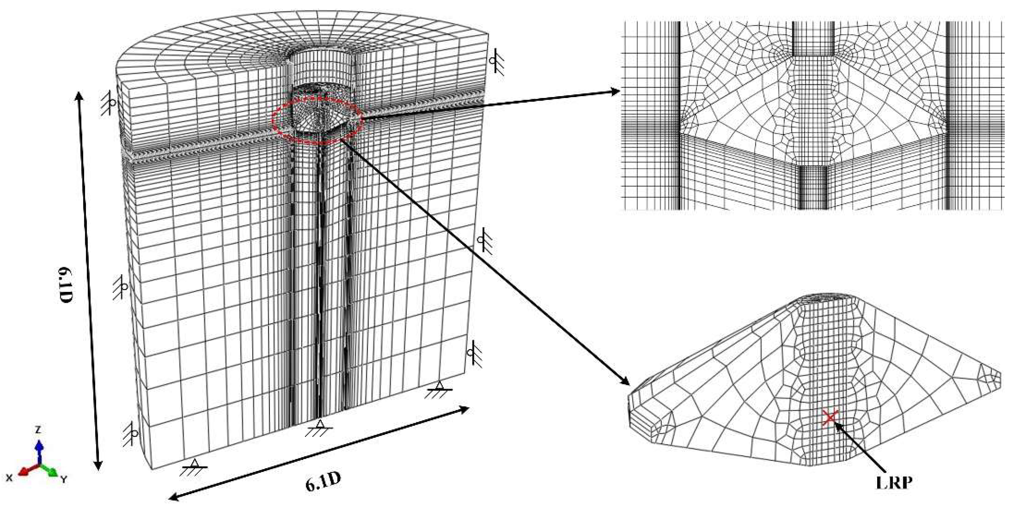
A typical mesh of the spudcan foundation is shown in Figure 2. The soil domain extends 6.1D radially and vertically to mitigate boundary effects. The model’s bottom boundary is fixed in all directions. The vertical sides are constrained horizontally but free to move vertically, a standard configuration that prevents unrealistic rigid body motion while permitting vertical settlement. The ground surface remains unconstrained. The spudcan is defined as a rigid body, while the soil is modeled as an ideal elastoplastic material conforming to the Tresca yield criterion [21]. For saturated clay under rapid, undrained loading, the Tresca yield criterion is appropriate as it accurately captures the material’s constant undrained shear strength [10,21]. The cavity above the spudcan was simulated as a regular cylinder with a diameter D. This simplification is supported by existing studies [3], which indicate that the cavity remains approximately cylindrical when the normalized penetration depth (d/D) is less than 2. Given the symmetry of the spudcan foundation under combined loading, a half-model is employed to enhance computational efficiency. The boundary conditions include radial constraints on the cylindrical surface, vertical constraints on the bottom surface, and symmetry constraints on the cut plane. To ensure simulation accuracy, the mesh at the spudcan–soil interface is refined, with element sizes maintained between 0.001D and 0.005D. After numerous attempts at mesh generation and sensitivity analysis, the soil domain is discretized with approximately 53,000 first-order, fully integrated hexahedral elements. All loads and displacements are applied to the LRP. The clay is tied to the spudcan, enforcing a perfect bond that prevents relative motion. This setting is chosen to model the suction effect that develops between the spudcan and clay [22].

2.2. Loading Techniques for Bearing Capacities

2.2.1. Swipe and Probe Loadings

Selecting an appropriate loading technique is crucial for minimizing deviation in numerical simulation results. The failure envelope has been used widely to assess the combined capacities of the spudcan. This envelope is typically determined through two loading techniques, the Swipe [23,24] and the Probe [25] tests. The simplified loading paths for these tests are illustrated in Figure 3. Using the i and j degree of freedom as an example, the Swipe loading technique involves first applying a displacement ui until the load in that direction reaches its ultimate capacity. ui is then held constant while a displacement uj is applied in the j-direction until the capacity in the j-direction becomes nearly stable. In the Probe technique, the displacements in the i- and j-directions are applied simultaneously at a fixed ratio until the capacities in both directions converge to constant values.

2.2.2. Use of Loading Techniques

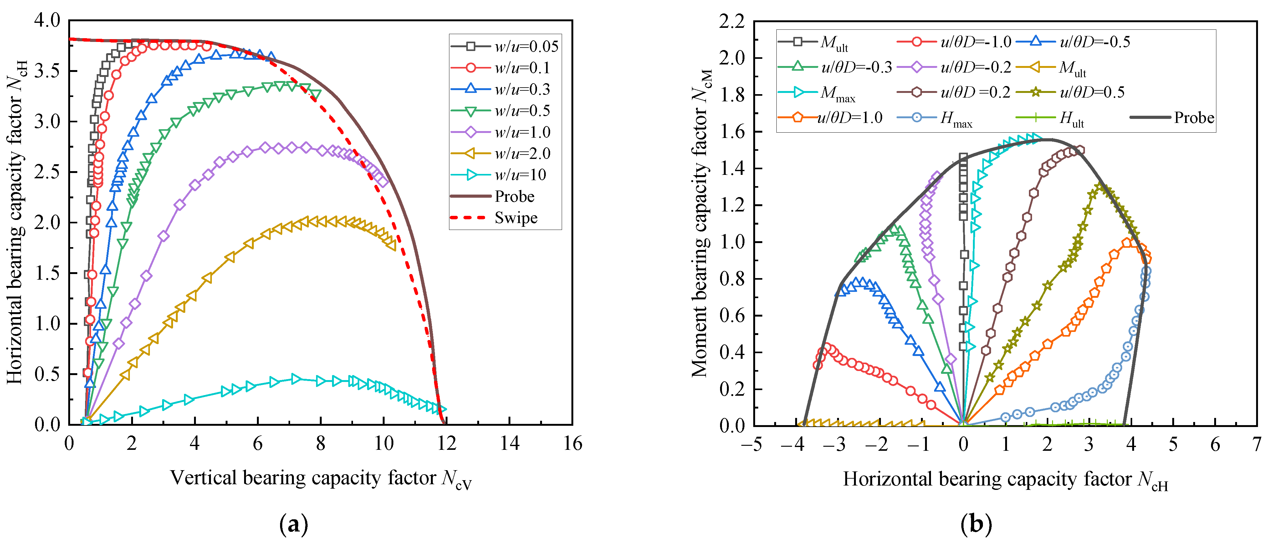
The Swipe technique offers a simple algorithm and high computational efficiency, in contrast to the more computationally intensive, iterative Probe technique. However, prior studies [26,27] indicated that Swipe underestimates the capacities in the V-H and H-M planes. Therefore, validating the effectiveness of the Probe technique for these planes is essential. To this end, using the existing model and the parameters from Group 4 in Table 1 as a representative case, a total of 19 simulations of Probe loading are conducted. The fixed displacement ratios for each simulation are listed in Table 3, and the results are presented in Figure 4. In Figure 4a, the V-H failure envelopes derived from the Probe and Swipe techniques are compared, revealing that the envelope generated by the latter is smaller than that from the former. This finding aligns with the conclusions drawn by Zhang et al. [17]. Consequently, the failure envelope obtained via the Probe technique offers a more accurate representation of the actual failure surface in the V-H plane. The Swipe technique is primarily employed for the V-M loading plane, where its efficiency in generating a complete failure envelope from a single analysis is well-established. However, for the V-H and H-M planes, the Swipe method proves inadequate, as it significantly underestimates the failure envelope. In these domains, the Probe technique is essential, providing a far more accurate representation of the actual failure surface. Therefore, a hybrid solution is employed to establish the envelope: the Swipe technique is used for the V-M load space, while the Probe is applied in the V-H and H-M planes.

2.3. Verification

The combined capacities are determined for a spudcan at a normalized penetration depth of d/D = 3.5 without cavity formation, i.e., for Group 4 in Table 2. The numerical results are then compared with the existing numerical and centrifuge data, as shown in Table 4. It is evident that the vertical capacity obtained here is slightly higher than the values reported by Hossain et al. [3,18,27] from both centrifuge tests and large-deformation numerical simulations. This discrepancy is mainly attributable to the fact that the strain softening of soil and strength redistribution caused by the spudcan penetration are not accounted for in this model. For practical design, engineers should therefore apply safety factors or perform site-specific verification when using these results, especially in softening-sensitive clay under cyclic loading, to avoid overestimating foundation capacity. However, the vertical capacity factor differs by only approximately 3% from the small-deformation simulation results of Hossain et al. [3] and the theoretical shallow foundation solution proposed by Martin & Randolph [28]. Similarly, the moment capacity factor varies by merely 2% from the upper-bound theoretical solution developed by Eikhatib [29]. Furthermore, comparisons with the numerical results in Zhang et al. [5] reveal differences of only 2%, 0.2%, and 0.6% for the vertical (NcV), horizontal (NcH), and moment (NcM) factors, respectively. These comparisons indicate that the numerical model in this study provides a reasonable prediction of the capacities of the spudcan foundation.

3. Capacities of Spudcan in Clay with Variable Strength

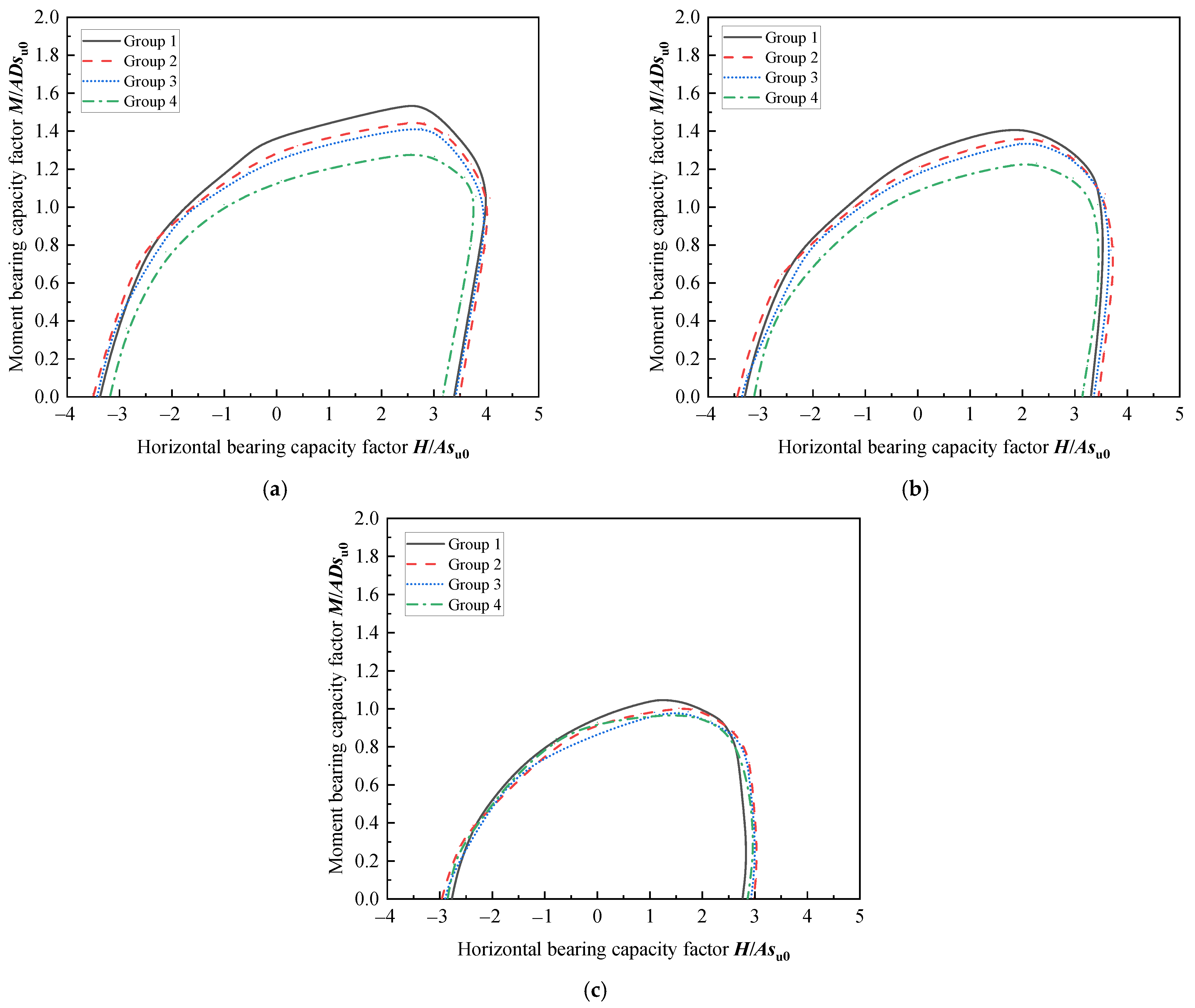
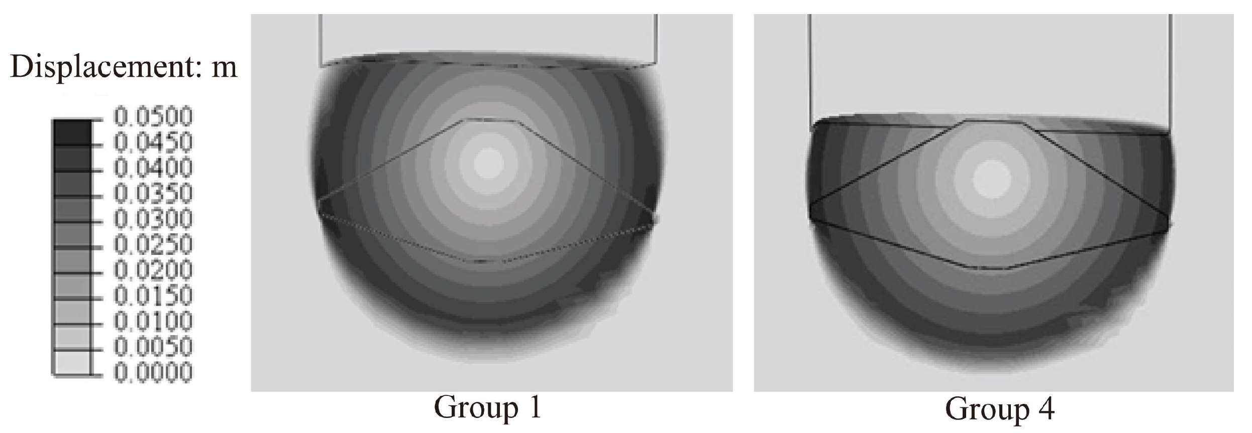
To evaluate the influence of clay strength parameters and ultimate cavity depth on the accuracy of the composite bearing capacity failure envelope, numerical simulations are performed using the four soil parameter sets listed in Table 2. Since the maximum cavity depth formed during spudcan penetration varies with clay strength, the ultimate cavity depths in this analysis are sequentially set to 0.5D, 0.41D, 0.4D, and 0.3D. Figure 5 illustrates the evolution of the failure envelope in the H-M plane under different vertical load levels (V/Vult = 0, 0.5, and 0.75) and varying soil parameters at a normalized penetration depth of d/D = 0.75. The results demonstrate that cavity depth significantly influences the size of the failure envelope, even at a constant penetration depth. Specifically, the failure envelope of Group 1 is substantially larger than that of Group 4. This discrepancy is most pronounced under high moment loads but gradually diminishes as the vertical load increases. To better visualize the behavior at the ultimate moment capacity (M = Mult), soil displacement contour plots are generated for Groups 1 and 4 at a normalized penetration depth of d/D = 0.75, revealing significant differences in their failure envelopes, as shown in Figure 6. The results indicate that, at the same burial depth, the spudcan in Group 1 exhibits a greater volume of soil backflow above it. Consequently, upon instability, the zone of soil mobilized in Group 1 is considerably larger than that in Group 4. This suggests that while higher soil strength corresponds to greater bearing capacity at the same penetration depth, it also results in a relatively smaller zone of soil displacement during failure.

4. Prediction of Failure Envelope

4.1. Prediction Equation

Previous studies [5,30] have shown that the empirical expressions of the failure envelope achieve higher accuracy at normalized penetration depths of d/D ≥ 1.5. However, the practices in harder clays are usually with d/D < 1.5, rendering the existing equations developed for soft clay inapplicable. Following the approach of Zhang et al. [5], the numerical results in Figure 5 are used to derive a new equation for the failure envelope in hard clay, as follows:
f = c 1 ( H h 0 V ult ) 2.5 + c 2 ( M m 0 D V ult ) 3 2 c 1 c 2 e H M h 0 m 0 D V ult 2 + V V ult 2 1 = 0
where the normalized bearing capacity coefficients h0 and m0 are defined in Table 1. Unlike the existing equations [5] calibrated for deep penetration in soft clays, Equation (2) incorporates newly fitted shape parameters c1 and c2, derived from least squares regression of the failure envelope data from Figure 5, specifically enhancing its accuracy for spudcans at shallow penetration depths in high-strength clay. The parameters c1 and c2’s specific calculation methods are provided below:
c1 = 1 − c3(v3v4)
c2 = 1 − c4(v3v4)
The values of coefficients c3 and c4 depend on the normalized penetration depth relative to the limiting cavity depth. When the spudcan depth reaches the limit cavity, i.e., 0.1 ≤ d/D ≤ 0.5, the values of c3 and c4 are 3.5 and 1.5, respectively. When the spudcan depth exceeds the limit cavity, i.e., d/D > 0.5, the values are changed to 2.0 and −5.0, respectively. The parameter e represents the eccentricity of the failure envelope in the H-M plane, of which the magnitude varies with vertical load according to the following:
e = e1 + e2v2
where e1 denotes the envelope eccentricity under zero vertical load, while e2 describes the eccentricity under varying vertical load conditions.

4.2. Parameter Fitting

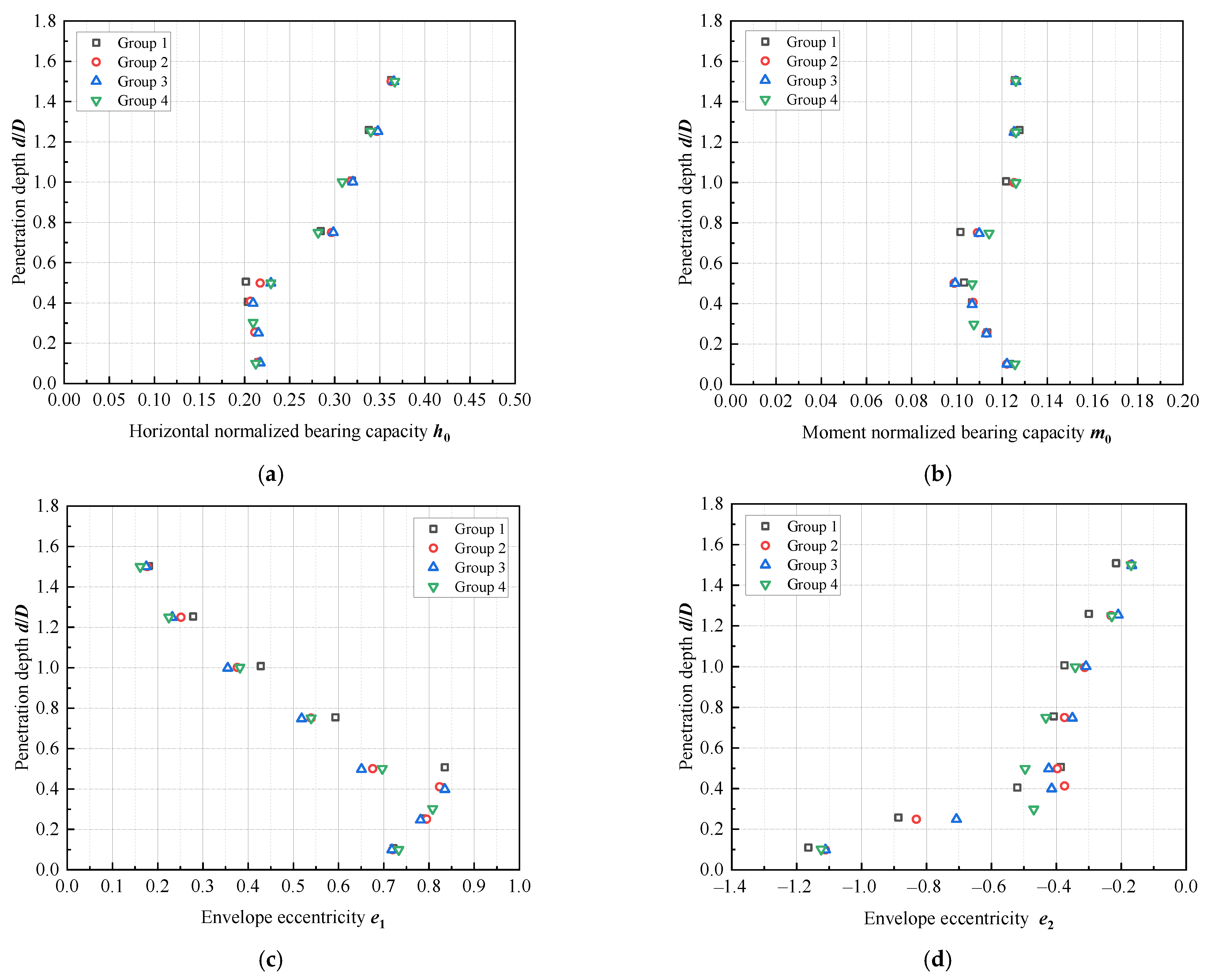
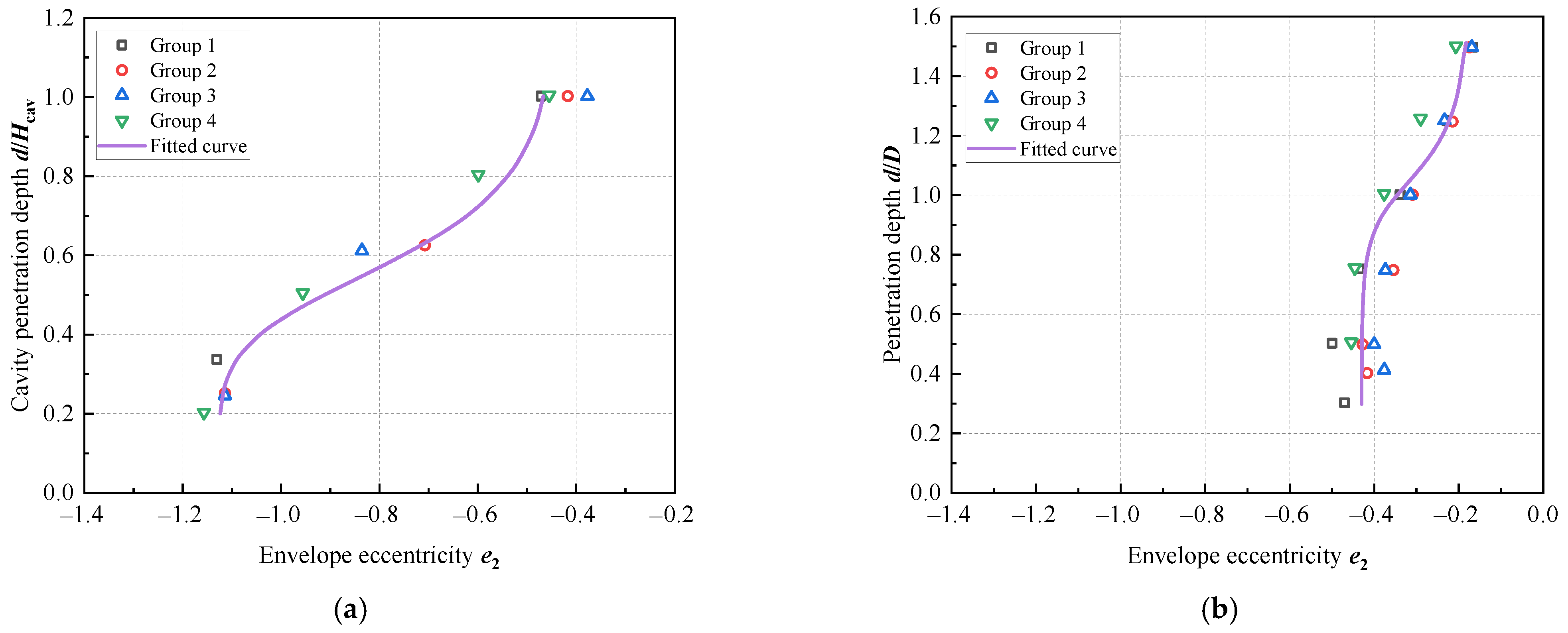
Based on the proposed composite bearing capacity envelope prediction Equation (2), the normalized bearing capacity coefficients h0 and m0, along with the shape parameters e1 and e2, are calculated for soils of varying strength (Groups 1–4 in Table 2). These parameters are found to vary with burial depth, as illustrated in Figure 7. The results indicate that variations in each coefficient are minimal at shallow penetration depths. However, significant changes occur beyond a threshold (d/D > 0.5), particularly in the shape parameters e1 and e2. To enhance parametric accuracy, the limiting cavity depth Hcav is adopted as a reference value, with its magnitude determined by the expression proposed by Hossain and Randolph [27] as follows:
H cav D = S 0.55 S 4
where
S = ( s um γ D ) ( 1 k / γ )
The specific values of the parameters are shown in Table 2. Accordingly, the prediction of envelope parameters is categorized into two cases: dHcav and d > Hcav. The corresponding fitted equations for each parameter, derived using the least squares method, are as follows:
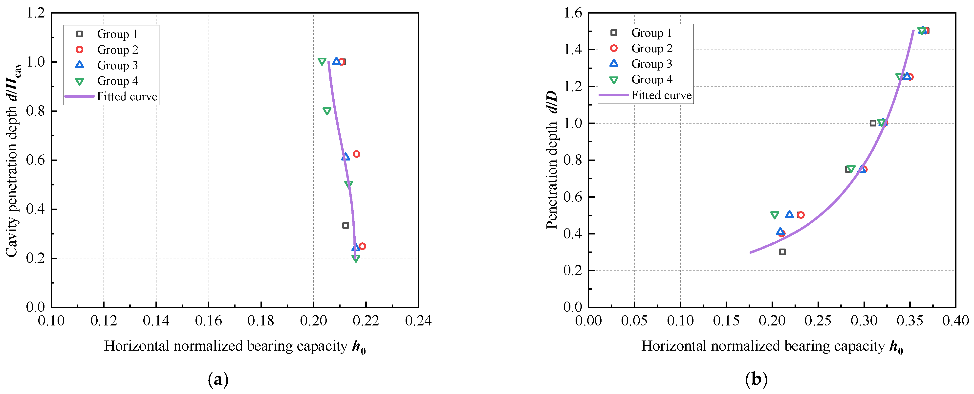
h 0 = h 0 s + h 0 cav h 0 s 1 / ( 0.63 + 0.15 ( d H cav ) 4.23 )                               d     H cav h 0 = h 0 d + h 0 cav 2 1 / ( 1 0.55 ( d D ) 0.15 )                                                                 d   >   H cav
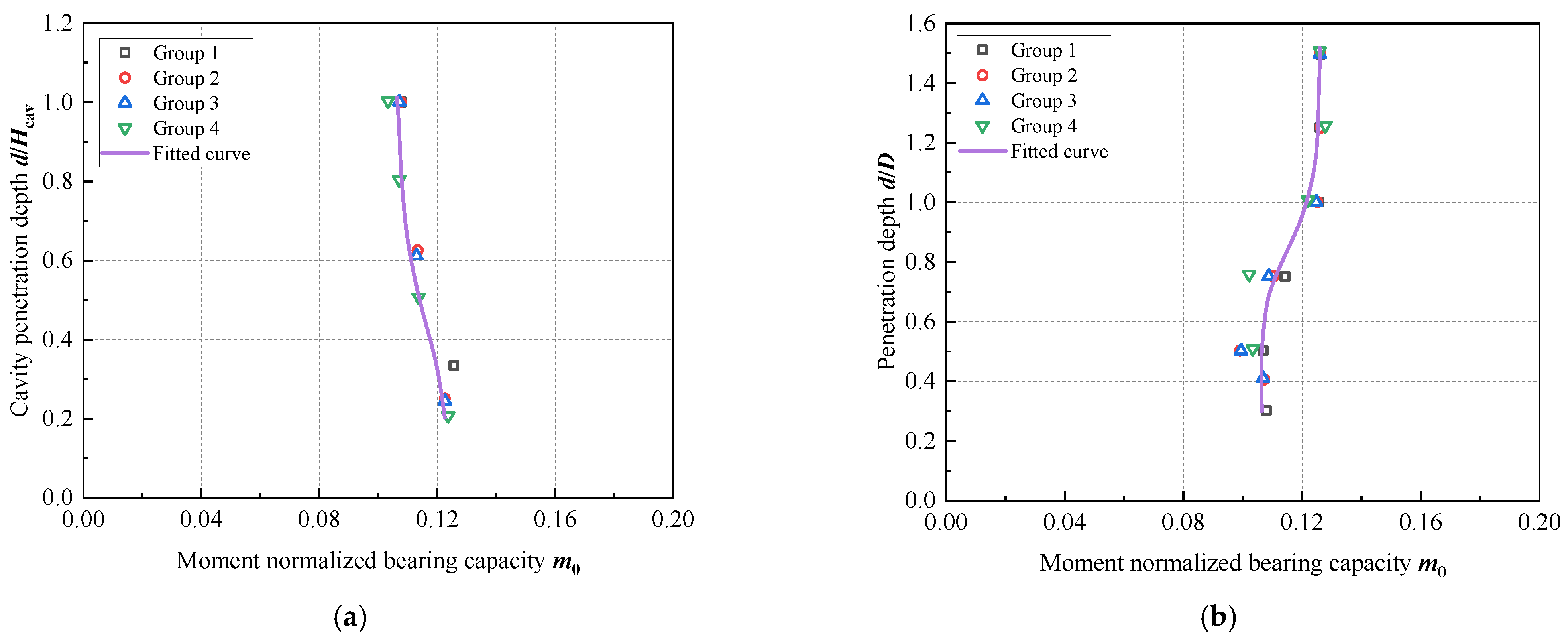
m 0 = m 0 s + ( m 0 cav m 0 s ) 1 / ( 1 + 0.065 ( d H cav ) 4.2 )                               d     H cav m 0 = m 0 d + ( m 0 cav m 0 d ) 1 + 1.16 ( d D ) 8.37 )                                                             d   >   H cav
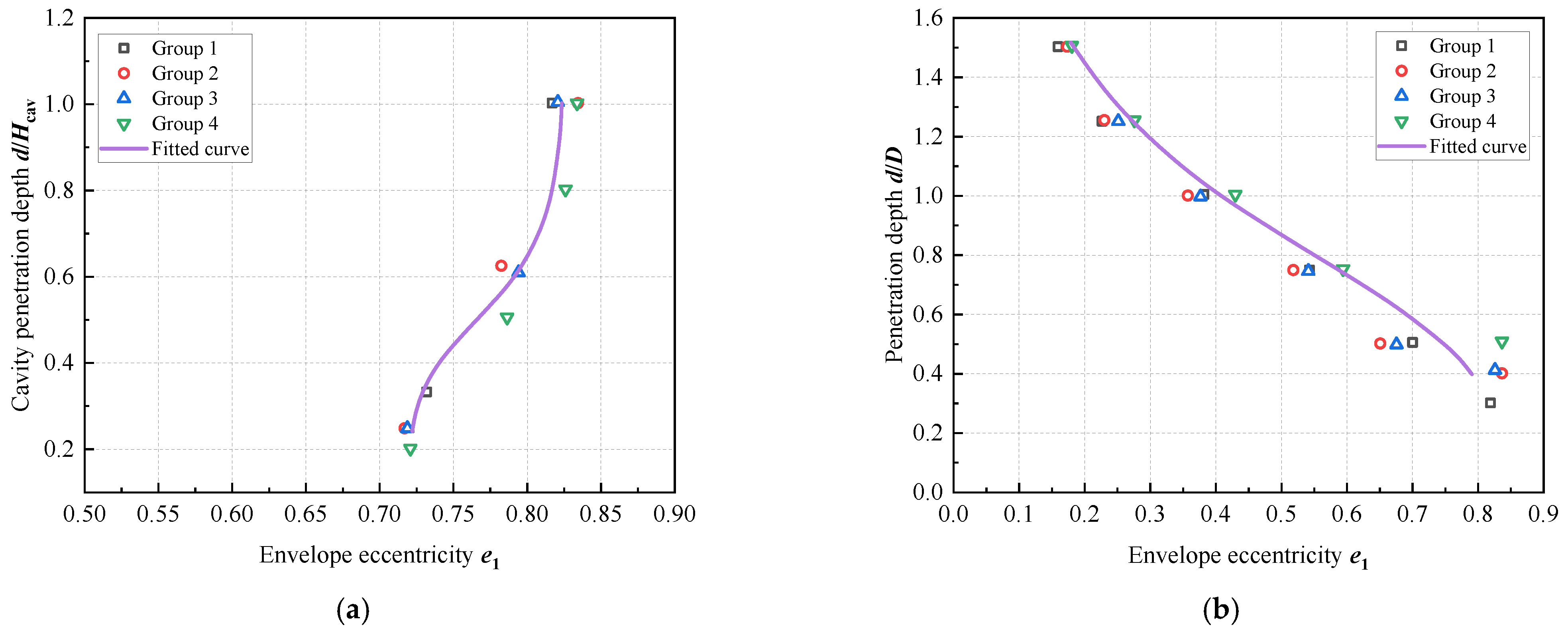
e 1 = e 1 s + ( e 1 cav e 1 s ) 1 / ( 1 + 0.03 ( d H cav ) 5.46 )                                                 d     H cav e 1 = e 1 cav + ( e 1 d e 1 cav ) 1 / ( 0.83 + 0.73 ( d D ) 3.25 )                                       d   >   H cav
e 2 = e 2 s + ( e 2 cav e 2 s ) 1 / ( 1 + 0.055 ( d H cav ) 5.37 )                                               d     H cav e 2 = e 2 cav + ( e 2 d e 2 cav ) 1 1 / ( 1 + 0.51 ( d D ) 10.75 )                             d   >   H cav
The fitted values for the parameters in the above equations are presented in Table 5, with the corresponding fitting results illustrated in Figure 8, Figure 9, Figure 10 and Figure 11. An agreement is achieved between the numerical data and the equation.

4.3. Verification of Prediction Results

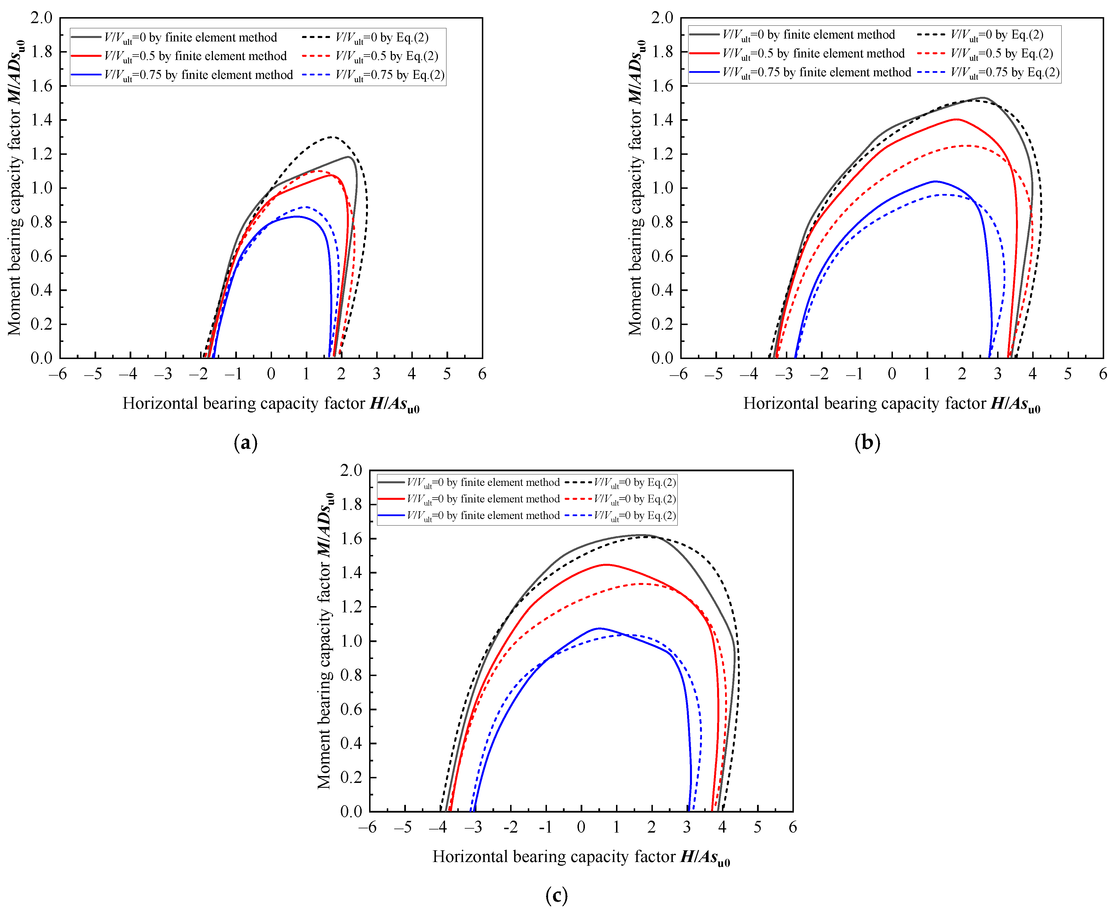
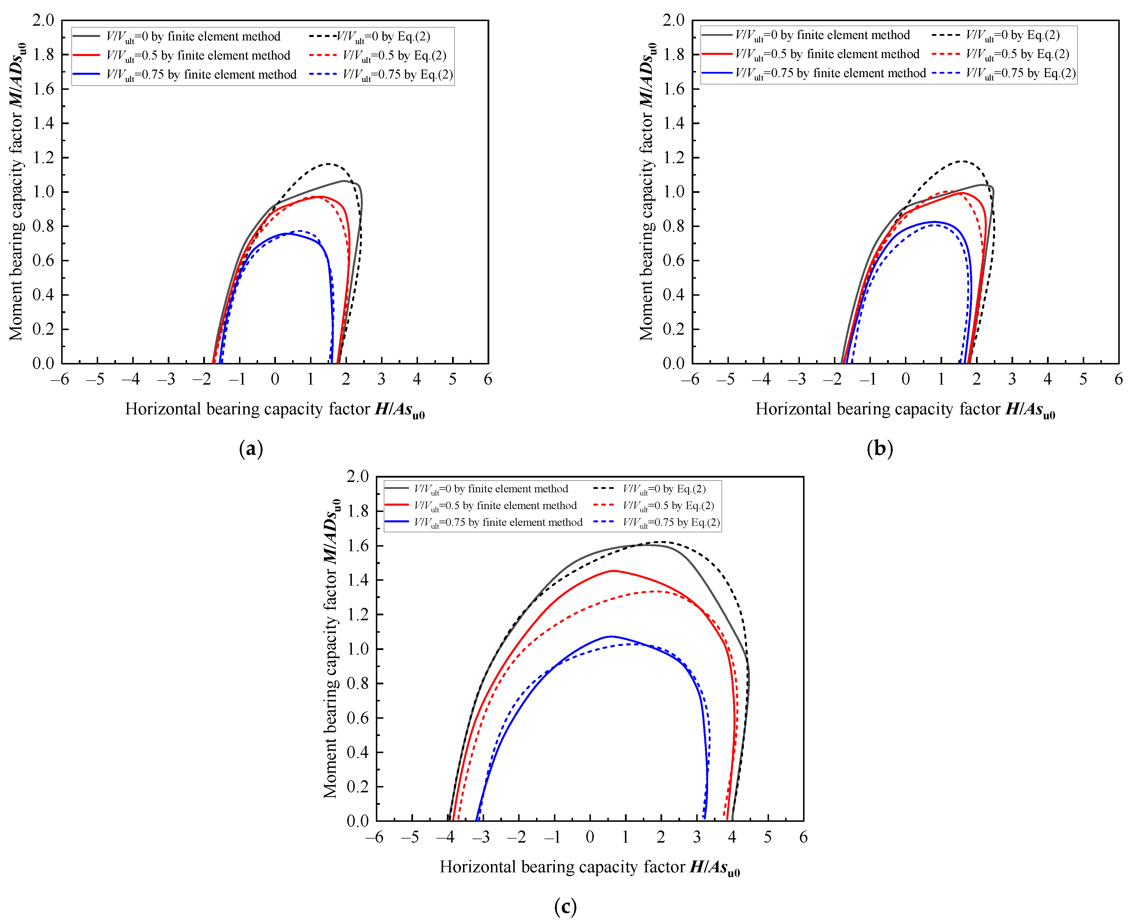
To further validate the prediction equation, the results from Equation (2) are compared against numerical simulations for Groups 1 and 2 (Table 2), as shown in Figure 12 and Figure 13. The predicted values demonstrate strong agreement with the numerical results, particularly under conditions of higher soil strength and when the vertical load V approaches the ultimate bearing capacity Vult, where the fit is notably better. As illustrated by the Group 1 results in Figure 12, the proposed equation accurately predicts the composite bearing capacity envelope at a normalized penetration depth equal to the limiting cavity depth (d/D = 0.3), especially under vertical load ratios of V/Vult = 0.5 and 0.75. However, the prediction accuracy slightly decreases at a greater depth of d/D = 0.75. Despite this, the overall error between the predicted and numerically simulated envelopes for V/Vult = 0.5 and 0.75 remains low, ranging from only 3% to 10%. Furthermore, predictive performance improves again at even greater penetration depths. In summary, the proposed composite bearing capacity envelope equation serves as an effective predictive tool for assessing the behavior of spudcan foundations in hard clay.

5. Conclusions and Limitations

This study investigates the bearing capacity of spudcan foundations in hard clay strata. The finite element method is employed to analyze the combined capacities of the spudcan, leading to an empirical expression of the failure envelope specifically tailored for hard clays. The accuracy of the proposed equation is validated through comparisons between theoretical and numerical results. The main conclusions are drawn as follows:
(1)
By employing a finite element method in conjunction with the combined Swipe (for the V-M load plane) and Probe (for the V-H and H-M load planes) loading techniques, the combined capacities of the spudcan in hard clay are accurately predicted. The results show reasonable agreement with the existing centrifuge data, theoretical solutions, and small-deformation results, with errors within 3%.
(2)
The size of the failure envelope is highly sensitive to soil strength and cavity depth. Higher undrained shear strength in hard clay corresponds to greater bearing capacity and reduced soil displacement at failure. Under combined V-H-M loading, deeper cavities (Hcav/D ≥ 0.5) reduce the envelope size.
(3)
The proposed equation of the failure envelope for the V-H-M includes the normalization coefficient h0 and m0, and the shape parameters e1 and e2 fitted against the spudcan depth. Comparisons with numerical results show that the error of the equation suggested is less than 10% when V/Vult = 0.5 and 0.75. Moreover, as the spudcan depth and soil strength are increased, the accuracy of the prediction may be improved further.
(4)
The proposed equation is validated for a specific range of soil strength and cavity conditions, and its applicability to more complex scenarios requires further verification. The Tresca model may oversimplify soil behavior under cyclic loading. Future research should include physical model tests (e.g., centrifuge experiments) and advanced constitutive models to account for cyclic degradation and rate effects. The methodology could also be extended to applications like offshore wind turbine foundations, which involve complex environmental loads.
(5)
This study validates the proposed method for shallow to moderate penetration depths in hard clays. The method may be less suitable for conditions involving strong strain softening, partial interface slip, or highly irregular cavity geometries. The model’s idealization of a cylindrical cavity with a perfectly bonded interface may overestimate capacity in scenarios with significant soil disturbance or interface slip. For preliminary design, the calculated capacities should be considered potentially non-conservative, and engineers must apply appropriate safety factors to mitigate the risk of overestimation.

Author Contributions

Conceptualization, M.W. and X.Y.; methodology, Y.C. and D.W.; software, X.Y. and Y.C.; validation, M.W., X.Y., Y.C., D.W., and H.S.; formal analysis, D.W.; investigation, X.Y. and Y.C.; resources, M.W. and H.S.; data curation, X.Y. and Y.C.; writing—original draft preparation, X.Y.; writing—review and editing, D.W. and Y.C.; visualization, M.W. and H.S.; supervision, D.W.; project administration, M.W. and H.S.; funding acquisition, D.W. All authors have read and agreed to the published version of the manuscript.

Funding

This research was funded by the National Natural Science Foundation of China, grant numbers 52394251 and 42025702.

Data Availability Statement

Data is contained within the article.

Conflicts of Interest

Mingyuan Wang was employed by PowerChina Huadong Engineering Corporation Limited. Yangbin Chen was employed by PowerChina Guangxi Engineering Corporation Limited. Huimin Sun was employed by Windey Energy Technology Group Co., Ltd. The remaining authors declare that the research was conducted in the absence of any commercial or financial relationships that could be construed as a potential conflict of interest.

References

  1. Suryasentana, S.K.; Dunne, H.P.; Martin, C.M.; Burd, H.J.; Byrne, B.W.; Shonberg, A. Assessment of numerical procedures for determining shallow foundation failure envelopes. Geotechnique 2019, 70, 60–70. [Google Scholar] [CrossRef]
  2. Teh, K.L.; Cassidy, M.J.; Leung, C.F.; Chow, Y.K.; Randolph, M.F.; Quah, C.K. Revealing the Bearing Capacity Mechanisms of a Penetrating Spudcan through Sand Overlying Clay. Geotechnique 2008, 58, 793–804. [Google Scholar] [CrossRef]
  3. Hossain, M.S.; Randolph, M.F.; Hu, Y.; White, D.J. Cavity Stability and Bearing Capacity of Spudcan Foundations on Clay. In Proceedings of the Offshore Technology Conference, Houston, TX, USA, 1 May 2006. [Google Scholar]
  4. SNAME. T&R Bulletin 5-05 A: Guidelines for Site Specific Assessment of Mobile Jack-Up Units. 2008. Available online: https://sname.org/node/1810 (accessed on 5 September 2025).
  5. Zhang, Y.; Bienen, B.; Cassidy, M.J.; Gourvenec, S. The Undrained Bearing Capacity of a Spudcan Foundation under Combined Loading in Soft Clay. Mar. Struct. 2011, 24, 459–477. [Google Scholar] [CrossRef]
  6. Li, L.; Li, J.; Huang, J.; Gao, F.P. Bearing Capacity of Spudcan Foundations in a Spatially Varying Clayey Seabed. Ocean Eng. 2017, 143, 97–105. [Google Scholar] [CrossRef]
  7. Wu, Y.; Zhang, H.; Shu, S. Probabilistic Bearing Capacity of Spudcan Foundations under Combined Loading in Spatially Variable Soils. Ocean Eng. 2022, 248, 110738. [Google Scholar] [CrossRef]
  8. Choi, J.; Jang, B.S.; Ju, H.; Han, S. Undrained Bearing Capacity of Spudcan in Soft-over-Stiff Clay after Penetration. Ocean Eng. 2021, 235, 109369. [Google Scholar] [CrossRef]
  9. Tho, K.K.; Leung, C.F.; Chow, Y.K.; Swaddiwudhipong, K. Improved Prediction of Spudcan Penetration Resistance by an Observation-Optimized Model. Int. J. Geomech. 2010, 12, 64–73. [Google Scholar] [CrossRef]
  10. Shu, S.; Gao, Y.; Wu, Y. Probabilistic bearing capacity analysis of spudcan foundation in soil with linearly increasing mean undrained shear strength. Ocean Eng. 2020, 204, 106800. [Google Scholar] [CrossRef]
  11. Bandyopadhyay, P.; Teng, F.C. Analysis of pile-soil-excavation interaction and load transfer mechanism in multi-layered soil for an in-service pile group. Comput. Geotech. 2024, 171, 106378. [Google Scholar] [CrossRef]
  12. Qiu, G.; Grabe, J. Numerical Investigation of Bearing Capacity Due to Spudcan Penetration in Sand Overlying Clay.Pdf. Can. Geotech. J. 2012, 49, 1393–1407. [Google Scholar] [CrossRef]
  13. Li, X.; Zhang, A.; Zhang, Q.; Li, D. Predicting the Ultimate Bearing Capacity of Spudcan in Stiff-over-Soft Clay Based on a Failure Model Varying with Soil Parameter. Appl. Ocean Res. 2024, 148, 104026. [Google Scholar] [CrossRef]
  14. Wang, Y.; Cassidy, M.J.; Bienen, B. Numerical Investigation of Bearing Capacity of Spudcan Foundations in Clay Overlying Sand under Combined Loading. J. Geotech. Geoenviron. Eng. 2020, 146, 04020117. [Google Scholar] [CrossRef]
  15. Liu, Y.; Zheng, J.; Wang, D.; Liu, K. Capacity of Spudcan Foundation on Dense Sand Overlying Clay under Combined Loading. Ocean Eng. 2022, 266, 112980. [Google Scholar] [CrossRef]
  16. Yin, Q.; Dong, S. Combined Bearing Capacity of Spudcans on a Double Layer Deposit of Strong-Over-Weak Clays. J. Ocean Univ. China 2019, 18, 133–143. [Google Scholar] [CrossRef]
  17. Zhang, Y.; Bienen, B.; Cassidy, M.J.; Gourvenec, S. Undrained Bearing Capacity of Deeply Buried Flat Circular Footings under General Loading. J. Geotech. Geoenviron. Eng. 2012, 138, 385–397. [Google Scholar] [CrossRef]
  18. Hossain, M.S.; Hu, Y.; Randolph, M.F.; White, D.J. Limiting Cavity Depth for Spudcan Foundations Penetrating Clay. Geotechnique 2005, 55, 679–690. [Google Scholar] [CrossRef]
  19. Dassault Systèmes Simulia Corp. Abaqus, Version 6.11; Dassault Systèmes Simulia Corp.: Providence, RI, USA, 2011.
  20. Menzies, D.; Roper, R. Comparison of Jackup Rig Spudcan Penetration Methods in Clay. In Proceedings of the Offshore Technology Conference, Houston, TX, USA, 5 May 2008. [Google Scholar]
  21. Shuttle, D. Cylindrical cavity expansion and contraction in Tresca soil. Geotechnique 2007, 57, 305–308. [Google Scholar] [CrossRef]
  22. Purwana, O.A.; Leung, C.F.; Chow, Y.K.; Foo, K.S. Influence of Base Suction on Extraction of Jack-up Spudcans. Geotechnique 2005, 55, 741–753. [Google Scholar] [CrossRef]
  23. Martin, C.M.; Houlsby, G.T. Combined Loading of Spudcan Foundations on Clay: Laboratory Tests. Geotechnique 2000, 50, 325–338. [Google Scholar] [CrossRef]
  24. Tan, F.S. Centrifuge and Theoretical Modelling of Conical Footings on Sand. Doctoral Dissertation, University of Cambridge, Cambridge, UK, 1990. [Google Scholar]
  25. Li, L.; Li, J.; Huang, J.; Liu, H.; Cassidy, M.J. The Bearing Capacity of Spudcan Foundations under Combined Loading in Spatially Variable Soils. Eng. Geol. 2017, 227, 139–148. [Google Scholar] [CrossRef]
  26. Gourvenec, S.; Randolph, M. Effect of Strength Non-Homogeneity on the Shape of Failure Envelopes for Combined Loading of Strip and Circular Foundations on Clay. Geotechnique 2003, 53, 575–586. [Google Scholar] [CrossRef]
  27. Hossain, M.S.; Randolph, M.F. New Mechanism-Based Design Approach for Spudcan Foundations on Single Layer Clay. J. Geotech. Geoenviron. Eng. 2009, 135, 1264–1274. [Google Scholar] [CrossRef]
  28. Martin, C.M.; Randolph, M. Applications of Lower and Upper Bound Theorems of Plasticity to Collapse of Circular Foundations. In Computer Methods and Advances in Geomechanics; Taylor & Francis: Abingdon, UK, 2001; Volume 2, pp. 1417–1428. [Google Scholar]
  29. Elkhatib, S. The Behaviour of Drag-in Plate Anchors in Soft Cohesive Soils. Doctoral Dissertation, University of Western Australia, Crawley, Australia, 2006. [Google Scholar]
  30. Hu, P.; Cassidy, M. Two-Dimensional Bearing Capacity of a Spudcan in Clay After Penetrating Through Top Sand. Int. J. Offshore Polar Eng. 2020, 30, 493–500. [Google Scholar] [CrossRef]
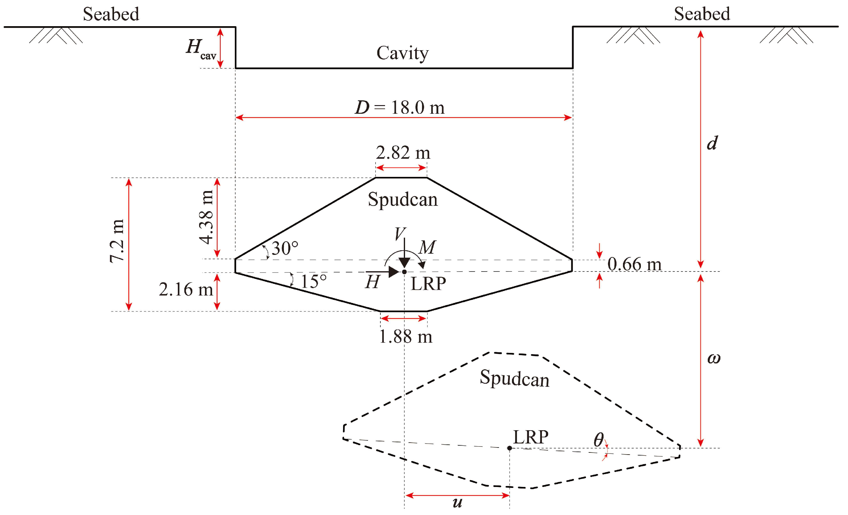
Figure 1. Schematic diagram of the size and penetration position of the spudcan.
Jmse 13 01899 g001
Figure 2. Dimensions and details of the spudcan model.
Jmse 13 01899 g002
Figure 3. Diagram of Swipe and Probe loadings.
Jmse 13 01899 g003
Figure 4. Calculation result of the Probe loading technique: (a) failure envelope of V-H plane; (b) failure envelope of H-M plane.
Jmse 13 01899 g004
Figure 5. Comparison of failure envelopes for clays with different strengths at penetration depth d/D = 0.75: (a) vertical load factor V/Vult = 0; (b) vertical load factor V/Vult = 0.5; (c) vertical load factor V/Vult = 0.75.
Jmse 13 01899 g005
Figure 6. Comparison of displacement contour lines (moment M = Mult, penetration depth d/D = 0.75, and vertical load factor V/Vult = 0).
Jmse 13 01899 g006
Figure 7. Variation of predicted parameters with spudcan penetration depth for different soil strengths: (a) horizontal normalized bearing capacity h0; (b) moment normalized bearing capacity m0; (c) envelope eccentricity e1; (d) envelope eccentricity e2.
Jmse 13 01899 g007
Figure 8. Fitting performance of the normalized bearing capacity coefficient h0 from Equation (8): (a) depth dHcav; (b) depth d > Hcav.
Jmse 13 01899 g008
Figure 9. Fitting performance of the normalized bearing capacity coefficient m0 from Equation (9): (a) depth dHcav; (b) depth d > Hcav.
Jmse 13 01899 g009
Figure 10. Fitting performance of the shape parameter e1 from Equation (10): (a) depth dHcav; (b) depth d > Hcav.
Jmse 13 01899 g010
Figure 11. Fitting performance of the shape parameter e2 from Equation (11): (a) depth dHcav; (b) depth d > Hcav.
Jmse 13 01899 g011
Figure 12. Failure envelopes under varying penetration depths for Group 1 in Table 2: (a) penetration depth d/D = 0.3; (b) penetration depth d/D = 0.75; (c) penetration depth d/D = 1.
Jmse 13 01899 g012
Figure 13. Failure envelopes under varying penetration depths for Group 2 in Table 2: (a) penetration depth d/D = 0.3; (b) penetration depth d/D = 0.75; (c) penetration depth d/D = 1.
Jmse 13 01899 g013
Table 1. The load and displacement notation used in this study.
VerticalHorizontalMoment
Load (N or N·m)V (N)H (N)M (N·m)
Unidirectional bearing capacity (N or N·m)Vult (N)Hult (N)Mult (N·m)
Bearing capacity factor (-)NcV = Vult/Asu0NcH = Hult/Asu0NcM = Mult/ADsu0
Normalized bearing capacity (-)n/ah0 = Hult/Vultm0 = Mult/DVult
Displacement (m or rad)w (m)u (m)θ (rad)
Table 2. Soil parameters adopted in the groups of benchmark cases.
Groupsum (kPa)k (kPa/m)Cavity Ratio Hcav/D
1101.50.3
2181.20.4
3201.50.41
4252.00.5
Table 3. Loading conditions of the Probe loading in the V-H and H-M planes.
Group (V-H)123456789101112
w/u (-)0.050.10.30.51.02.010.0n/an/an/an/an/a
Group (H-M)123456789101112
u/θD (-)−∞ (−Hult)−0.2−0.3−0.5−1.00 (Mult)0 (Mmax)0.20.51.0+∞ (Hmax)+∞ (Hult)
Table 4. The capacity factor in this study and the literatures.
Existing ResearchMethodsTypesNcVNcHNcM
Hossain et al. [18]Centrifuge testSpudcan11.0–12.0n/an/a
Hossain et al. [3]Small-deformation simulationSpudcan13.1n/an/a
Hossain et al. [27]Large-deformation simulationSpudcan11.3n/an/a
Martin & Randolph [28]Theoretical analysisThin plate13.11n/an/a
Eilkhatib [29]Theoretical analysisThin platen/an/a1.57
Zhang et al. [5]Small-deformation simulationSpudcan12.994.931.61
This studySmall-deformation simulationSpudcan12.734.941.60
Table 5. Specific parameter value in the prediction equation proposed in this study.
ParameterValueParameterValueParameterValueParameterValue
h0s0.216m0s0.123e1s0.72e2s1.124
h0cav0.208m0cav0.106e1cav0.827e2cav−0.43
h0d0.367m0d0.126e1d0.171e2d−0.182
Disclaimer/Publisher’s Note: The statements, opinions and data contained in all publications are solely those of the individual author(s) and contributor(s) and not of MDPI and/or the editor(s). MDPI and/or the editor(s) disclaim responsibility for any injury to people or property resulting from any ideas, methods, instructions or products referred to in the content.