1. Introduction
Sustainable economic growth fundamentally depends on secure energy provision. Recent global energy crises have underscored the imperative of energy self-sufficiency [
1]. Among renewable ocean energies, wave energy exhibits exceptional promise due to its high energy density, substantial inherent reserves, and environmental compatibility [
2,
3]. Two-body WECs have become prominent due to the structural simplicity, high conversion efficiency, cost-effectiveness, and deployment flexibility [
4,
5]. However, their near-shore deployment in low-energy wave regimes faces challenges such as limited power absorption efficiency [
6,
7]. Consequently, offshore deployment constitutes an inevitable trend, necessitating advanced floating two-body WECs for deep-water wave energy harvesting [
8,
9]. Current research focuses on three key aspects: configuration optimization, numerical simulation, and sea trials.
In terms of configuration optimization, Nazari [
10] demonstrated that optimized float geometry reduces the viscous–PTO damping disparity, enhancing resonance and power absorption. Son [
11] achieved threefold response enhancement in two-body WECs through shape optimization and parameter tuning to minimize viscous losses. Li [
12] and Amiri [
13] systematically investigated hydrodynamic sensitivity to the float radius and draft variations in two-body WECs. Tan [
14] augmented the added mass via damping plates at intermediate float bases, mitigating wave–structure interactions. Al [
15,
16] optimized submerged buoy and float configurations to enhance the motion response and energy capture efficiency. Payne [
17] utilized the boundary element method (BEM) for two-body WECs, quantifying the resonance period discrepancies between simulations and experiments. Kurniawan [
18] confirmed that enlarged submerged buoy diameters improve energy capture through shape optimization. Li [
19,
20] proposed a two-body WEC consisting of a surface-floating streamlined float and a deep-draft slender cylindrical buoy. The streamlined geometry reduces viscous energy dissipation and enhances motion response characteristics. For such WECs, the mass increase of the outer float or damping plates on the inner buoy [
21,
22] enhances stability, while large-amplitude outer buoy motion significantly improves the relative motion.
In terms of numerical simulation, Falcao [
23] employed frequency domain BEM simulations to optimize energy capture for the WEC under regular or irregular waves, refining the riser dimensions and PTO parameters. Bosma [
24,
25] established frequency domain and time domain BEM models for PowerBuoy, characterizing the hydrodynamic performance and energy extraction in both inviscid and viscous flow regimes. Xu [
26,
27] enhanced the BEM accuracy for WEC hydrodynamics through optimized free-surface Green’s function solutions. Ruehl [
28] advanced time domain modeling for two-body WECs, capturing nonlinear viscous effects and hydraulic PTO coupling dynamics. Ma [
5] introduced empirical drag coefficients to model vortex-induced vibrations on submerged bodies, enhancing the response prediction fidelity. Ji [
29] incorporated nonlinear stiffness into vertically asymmetric two-body WEC models, achieving superior accuracy over linear simulations. Zhang [
30] implemented high-order BEM for time domain analysis of hydrodynamic characteristics. Wang [
31] integrated second-order irregular wave theory into numerical models, enabling accurate power absorption analysis under extreme sea states. Agyekum [
32] developed a test rig to simulate the electrical pulses of a wave energy converter, employing control algorithms to achieve enhanced power output.
In terms of sea trials, several two-body WECs have successfully undergone sea trials and been deployed in real marine environments. In 1994, Ocean Power Technologies developed the PowerBuoy [
33], incorporating a damping plate to increase the added mass and radiation damping. In 1999, Wavebob Ltd. in Ireland introduced the Wavebob converter [
4,
34], which completed prototype sea trials in 2006. In 2007, Oregon State University successfully conducted sea trials of the SeaBeav I converter [
35]. In 2011, the Guangzhou Institute of Energy Conversion deployed “Nezha I” near Wanshan Island, Zhuhai—a floating direct-drive WEC [
36]. In 2012, Shandong University developed a 120 kW two-body WEC, “SDU-I,” which underwent sea trials off the coast of Chengshantou, Shandong Province [
37]. An improved version, “SDU-II,” was deployed in 2016 [
38].
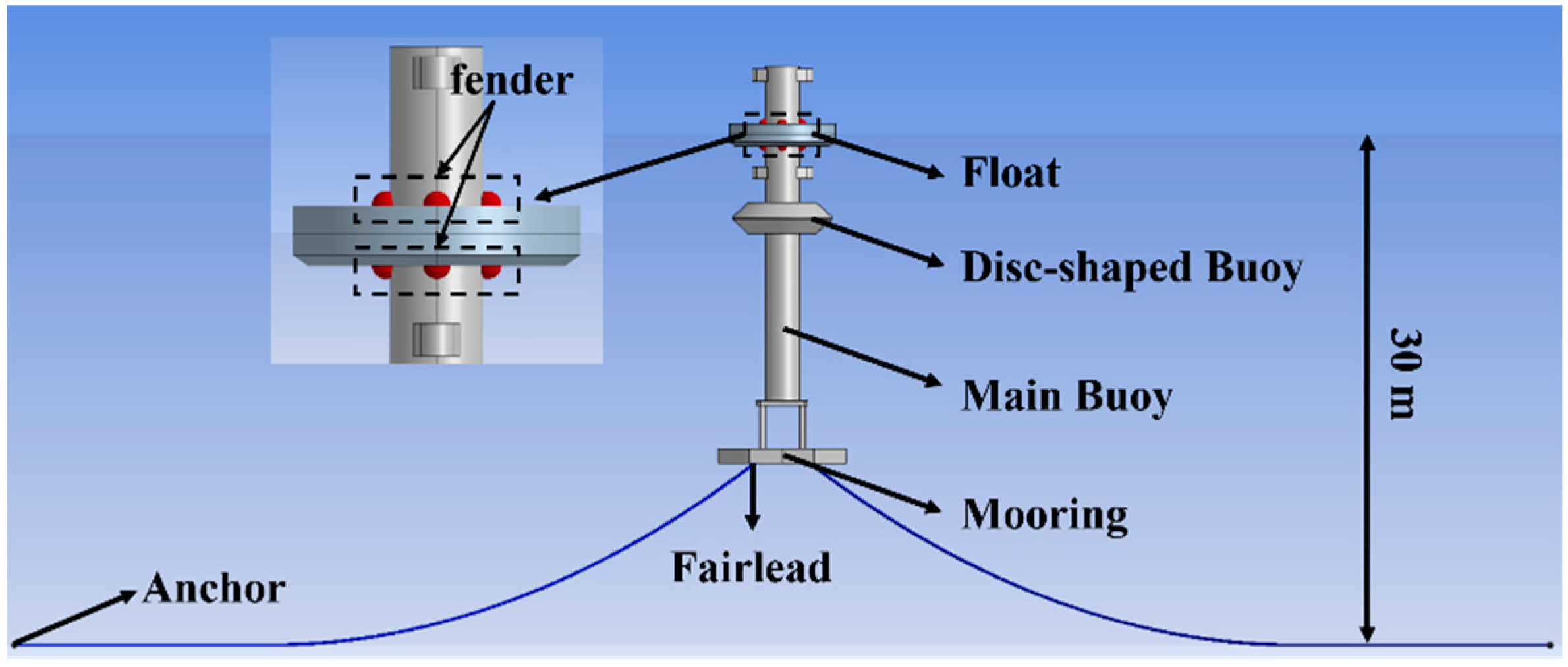
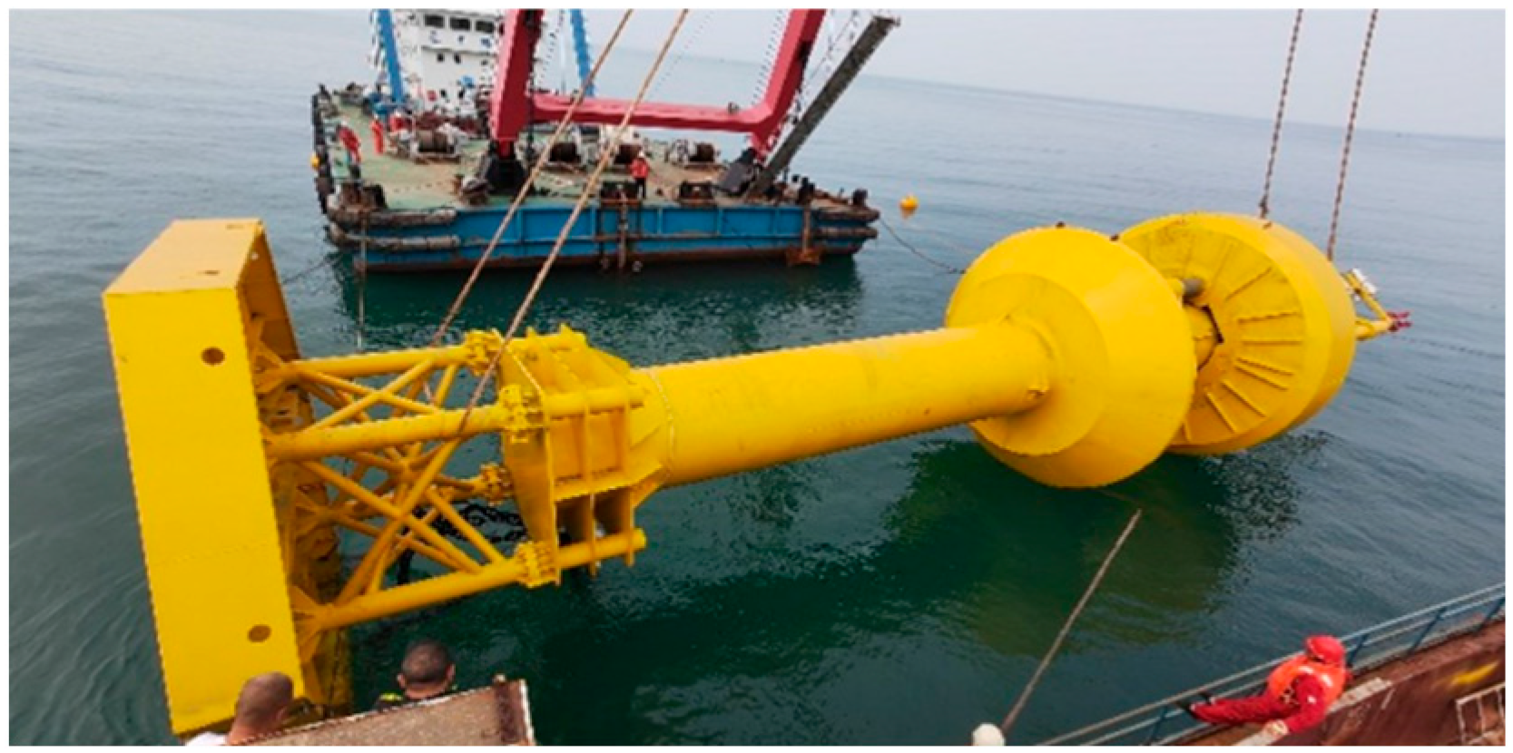
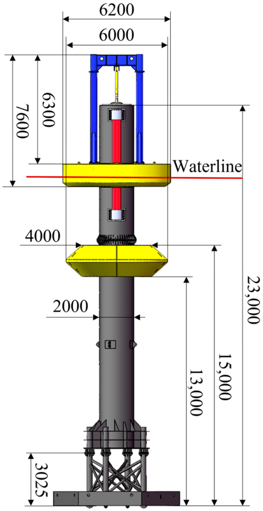
Current efforts predominantly focus on conventional two-body WEC optimization. Exploration of appendage integration and damping plate refinement for enhanced power absorption remains limited. Furthermore, existing numerical studies primarily examine the main buoy, with the hydrodynamic interactions in float and main buoy systems requiring deeper investigation. This study introduces a novel two-body WEC integrating a dish-shaped buoy and perforated damping plate. Building upon the SDU-II WEC, the proposed SDU-III WEC incorporates dish-shaped buoys and perforated damping plates, achieving enhanced stability, reduced mooring line tension, and improved power absorption. The research advantages are summarized in
Table 1. The remainder of this paper is organized as follows.
Section 2 outlines the theoretical background of the study.
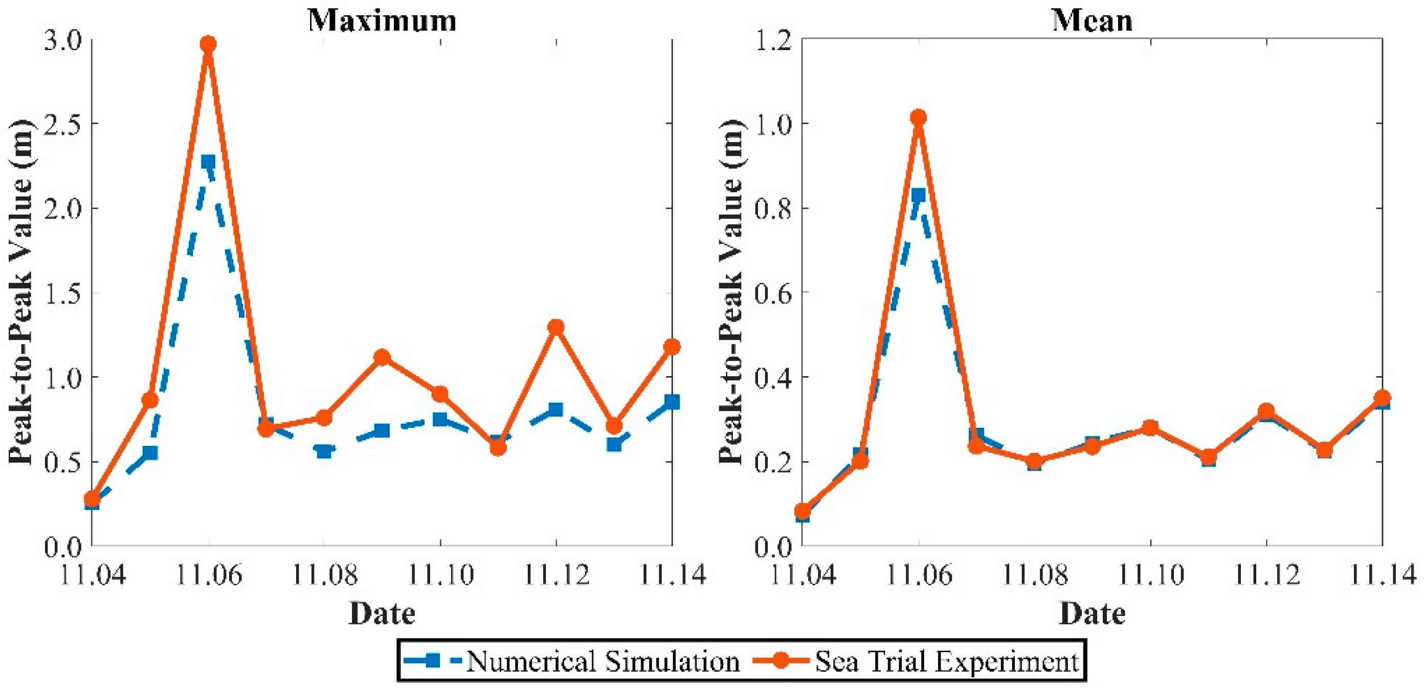
Section 3 details four two-body WECs featuring dish-shaped buoy and damping plate variations, with the corresponding numerical models developed. Then, it validates the hydrodynamic responses using experimental sea trial data.
Section 4 presents and discusses the results of the study.
Section 5 summarizes the main conclusions of the study.
4. Results and Discussion
4.1. Frequency Domain
Prior to domain response analysis of the WECs, frequency domain analysis based on potential flow theory is essential. Given the structural symmetry, the surge, heave, and pitch degrees of freedom at 0° wave incidence were analyzed. The frequency range spanned 0.1–5 rad/s.
Response amplitude operators (RAOs) quantify the phase relationship of the motion response to wave excitation and the power absorption characteristics.
Figure 16 shows RAO curves for the surge, heave, and pitch of the main buoys. Their surge and heave RAOs exhibit higher values with distinct low-frequency characteristics in the low-frequency region. The pitch RAOs change rapidly between 1.3 and 1.5 rad/s, with steep curves peaking in this range. The heave and pitch RAOs show secondary peaks at 0.7–0.9 rad/s and 0.2–0.3 rad/s, respectively. The main buoys with dish-shaped buoys show higher surge and heave RAOs but lower pitch RAOs. The differences in the surge RAOs are marginal, whereas the heave and pitch RAOs show significant variations. The peak RAO frequency range is narrower for the main buoys with dish-shaped buoys than without. Perforations in the damping plates minimally affect the surge, heave, and pitch RAO magnitudes. Solid damping plates yield slightly higher RAOs with narrower peak frequency ranges than perforated plates. The dish-shaped buoy significantly enhances the WEC’s power absorption potential and stability performance. While the perforated damping plate exhibits lower power absorption potential, it provides superior stability characteristics.
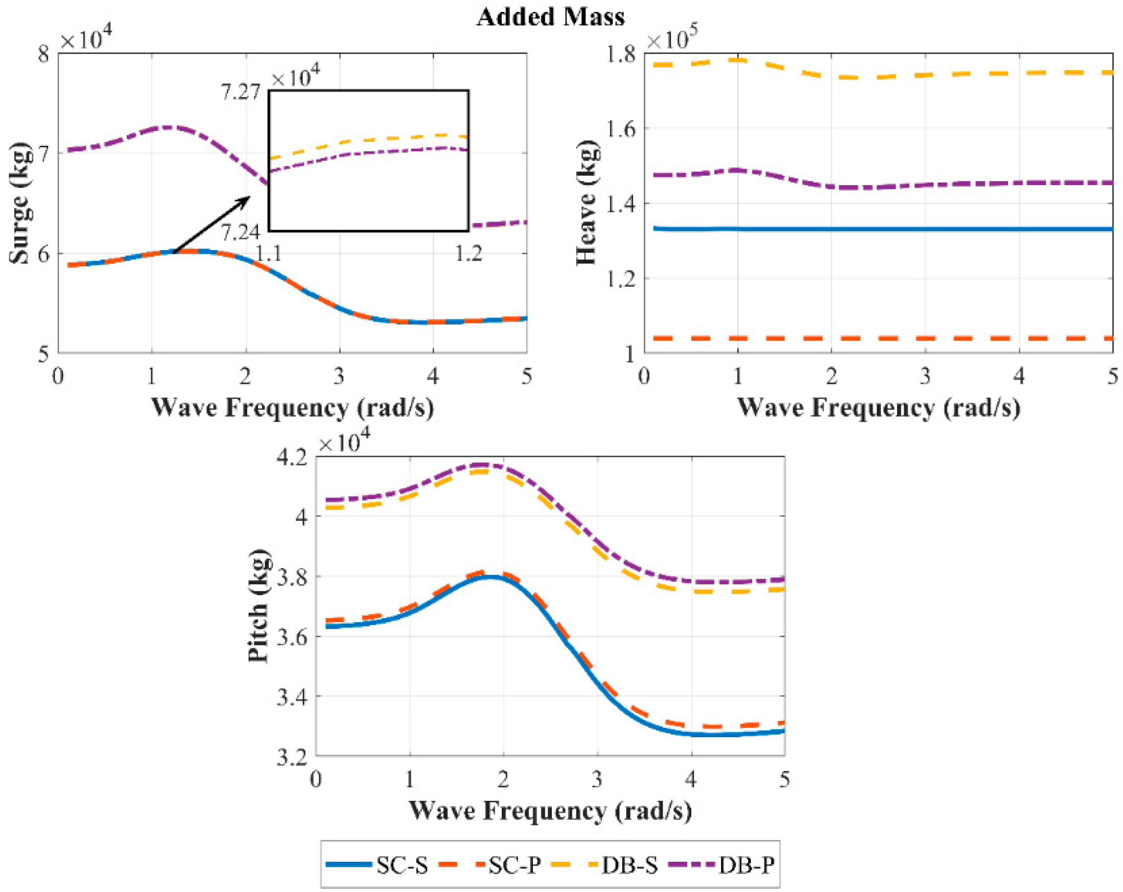
The added mass represents the inertial effect due to fluid motion relative to the body, being especially crucial for two-body systems.
Figure 17 presents the added mass variations for the surge, heave, and pitch degrees of freedom of the main buoys. The added mass for all the main buoys initially increases, then decreases, before increasing again across surge, heave, and pitch. For surge, the peak added mass occurs near 1.2 rad/s and the minimum near 3.7 rad/s. Heave peaks near 1 rad/s and reaches minimum near 2 rad/s. Pitch peaks near 1.8 rad/s with a minimum at 4.2 rad/s. The main buoys with dish-shaped buoys exhibit significantly higher added mass in surge, heave, and pitch than those without. Their peak added mass frequencies are also lower than in the simplified configuration. The perforated damping plate exhibits lower added mass in surge and heave, but higher values in pitch, with a particularly significant reduction in heave. Although the dish-shaped buoy exhibits lower response amplitudes, it enhances mooring stability. The perforated damping plate offers both enhanced response characteristics and favorable stability performance.
Radiation damping quantifies the energy dissipation through wave radiation, governing the power absorption potential. The radiation damping curves of the four main buoys are presented in
Figure 18. The radiation damping for the surge, heave, and pitch motions of all four main buoys exhibits consistent trends: initially increasing then decreasing with rising wave frequency. The peak radiation damping for surge occurs between 2.4 and 2.9 rad/s, while for heave, it ranges from 1.1 to 1.7 rad/s. The peak radiation damping for pitch occurs near 3 rad/s. In the surge and heave directions, the disc-shaped buoy enhances radiation damping. For pitch motion, however, the disc-shaped buoy reduces radiation damping and shifts the peak frequency: decreasing for surge but increasing for heave. The solid damping plate provides higher radiation damping than the perforated counterpart in the surge, heave, and pitch motions. The solid damping plate exhibits higher radiation damping in the surge, heave, and pitch directions than the perforated counterpart. The dish-shaped buoy and perforated damping plate significantly suppress the peak motion responses of the main buoy, enhancing device stability.
The wave excitation force drives the device. The wave excitation force variations for the four main buoys are presented in
Figure 19. For the surge, heave, and pitch degrees of freedom, all four main buoys exhibit wave excitation forces that generally increase initially then decrease with rising wave frequency. The surge excitation force peaks between 1.4 and 1.9 rad/s. The heave excitation force shows relatively high values at low frequencies, with a primary peak occurring at 0.9–1.2 rad/s and a secondary peak near 4.8 rad/s. For pitch excitation, the main peak appears at 2.2–2.4 rad/s and a secondary peak at 0.4–0.5 rad/s. The main buoys with the disc-shaped buoy yield greater wave excitation forces in surge and heave. Their corresponding peak frequencies for heave and pitch are higher than those without the buoy. The solid damping plate exhibits higher wave excitation forces than the perforated plate in the surge, heave, and pitch motions. The dish-shaped buoy and perforated damping plate enhance stability in pitch, with the former exhibiting high power absorption potential.
4.2. Motion Response
This study presents a systematic statistical analysis of one-year wave observation data from the deployment site of the WEC. The recorded waves predominantly occurred in sea states 3, 4, and 5 during the observation period. The most representative wave cases for each sea state were selected. Key parameters are summarized in
Table 6.
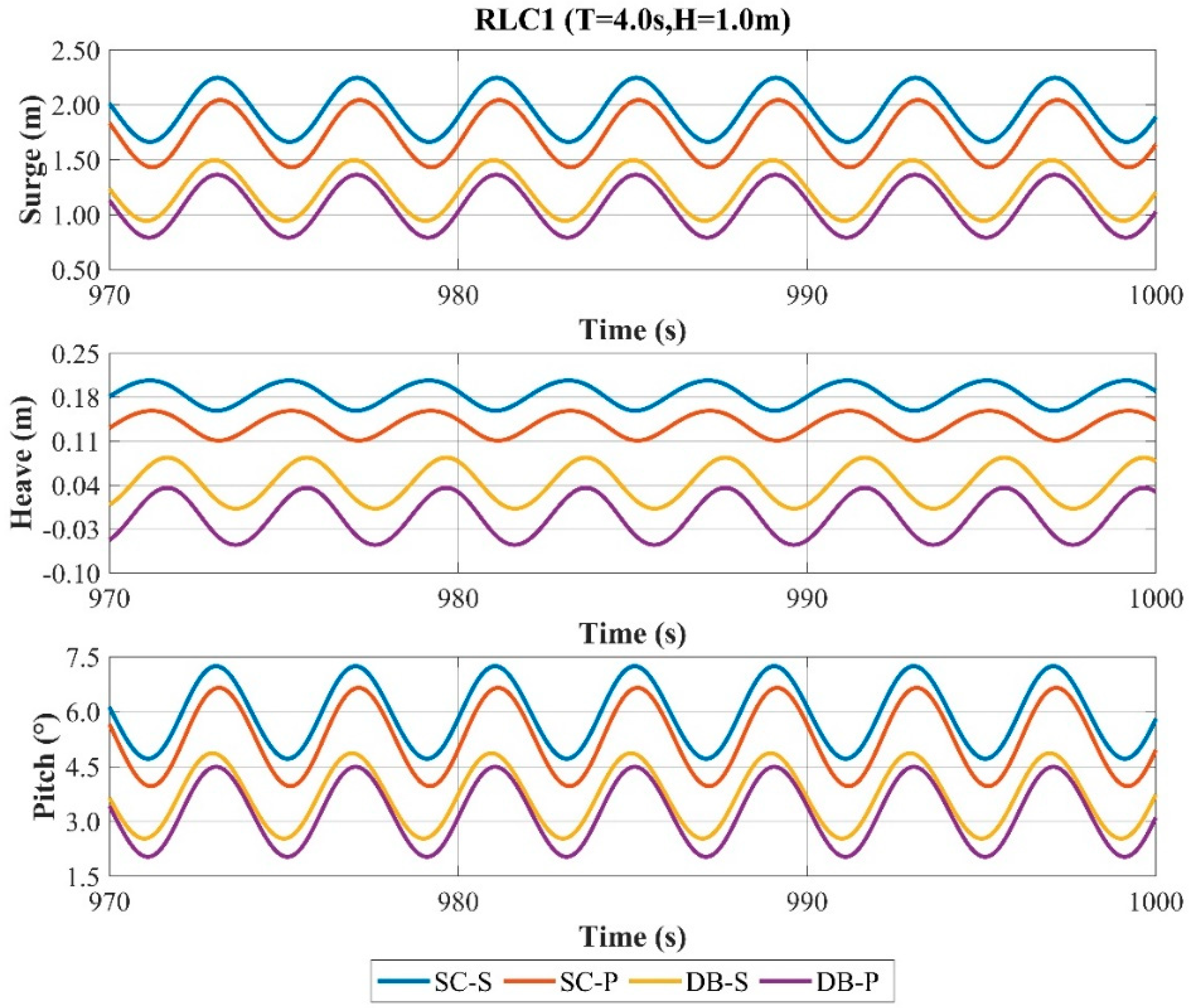
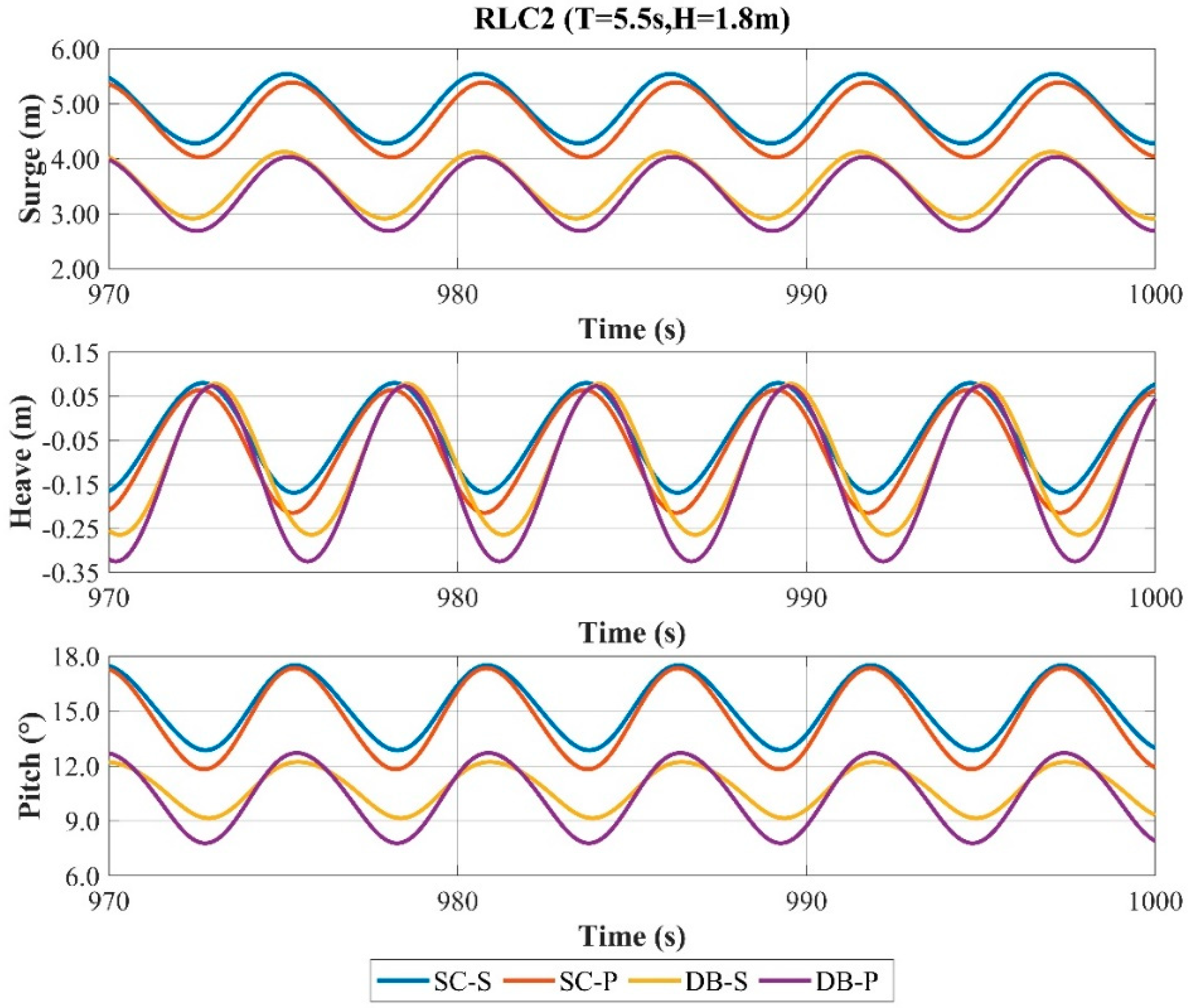
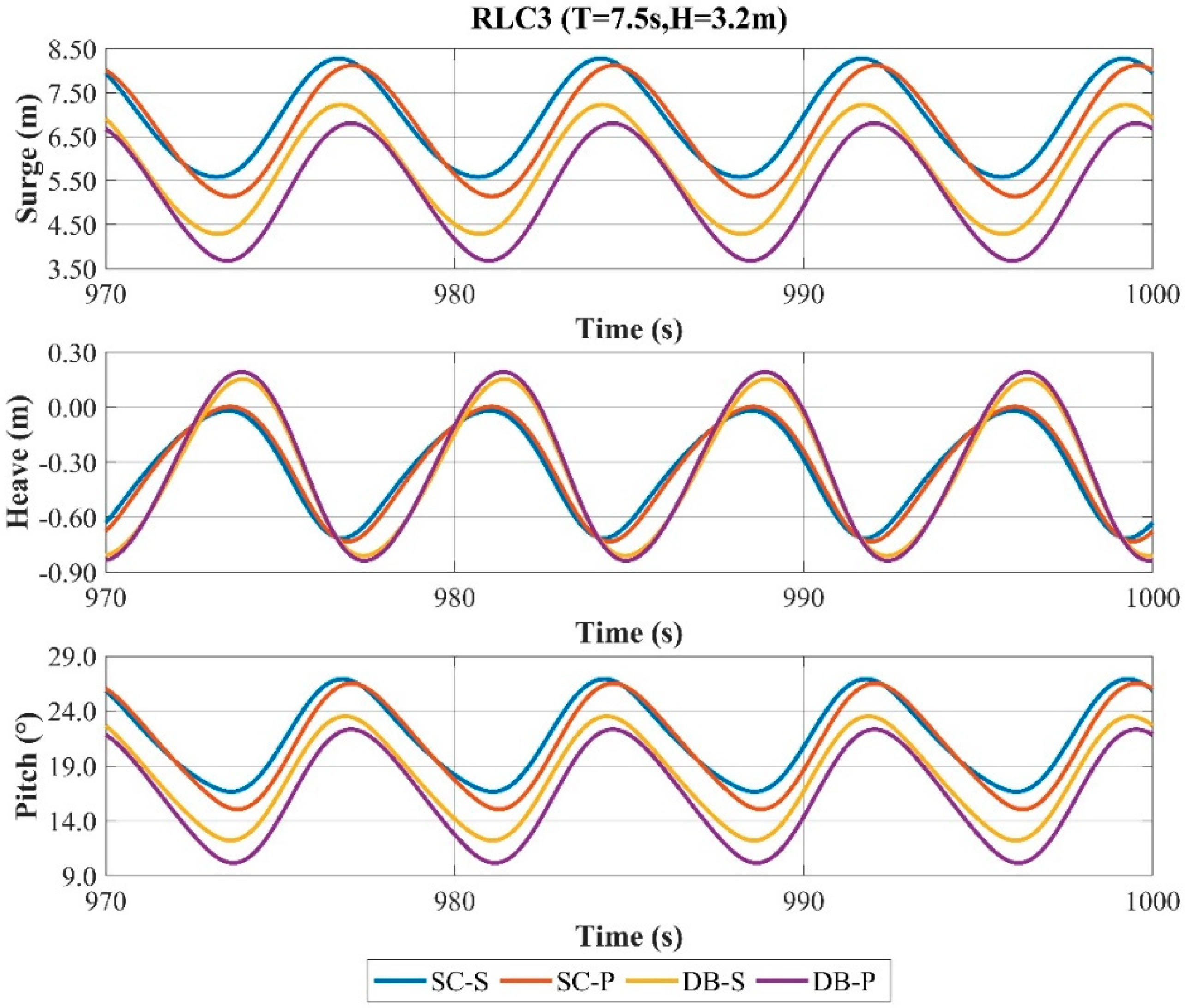
To assess the structural effects on platform motion,
Figure 20,
Figure 21 and
Figure 22 and
Table 7 present the motion responses of the four main buoys under three regular waves at 0° wave incidence. Structural and loading symmetry result in minimal motion amplitudes in the sway, roll, and yaw degrees of freedom. Consequently, only the surge, heave, and pitch motions are analyzed.
For the surge response, the peak values across the three wave cases consistently follow DB-P < DB-S < SC-P < SC-S. DB-P and DB-S exhibit similar peak values, both significantly lower than SC-P and SC-S. Respectively, DB-P and SC-P show lower peaks than DB-S and SC-S. Under the RLC1 and RLC2 wave cases, SC-P yields the maximum response amplitude, whereas DB-S gives the minimum. Under RLC3, DB-P produces the maximum amplitude and SC-S the minimum. The solid damping plate shows smaller amplitude but larger peak values than the perforated types across all wave cases. The disc-shaped buoy exhibits lower amplitude under RLC1 and RLC2 but higher under RLC3. Their peak values remain lower than the simplified configurations in all wave cases.
For the heave response, the peak values vary across wave cases among the four main buoys. Under RLC1, the peak responses follow DB-P < DB-S < SC-P < SC-S. For RLC2, the peak values are nearly identical across main buoys. Under RLC3, DB-P and DB-S exhibit comparable peaks, both exceeding those of SC-S and SC-P. Across all wave cases, DB-P and DB-S show higher amplitudes, with DB-P consistently exceeding the other main buoys. The disc-shaped buoy significantly affects the peak values in RLC1 and RLC3, while the simplified configuration yields smaller peaks. Perforated damping plates show significantly smaller peaks only under RLC1. Disc-shaped buoys yield consistently greater heave amplitudes than the simplified configuration across wave cases. Perforated damping plates enhance the heave amplitude more effectively than solid damping plates.
For the pitch response, under the RLC1 and RLC3 wave cases, the peak response magnitudes follow DB-P < DB-S < SC-P < SC-S for all the main buoys. DB-P and SC-P exhibit significant differences in the peak response, yet both are marginally lower than DB-S and SC-S, respectively. Across three wave cases, DB-P and DB-S demonstrate comparable peak responses, which are substantially lower than those of SC-P and SC-S. For the RLC1 and RLC2 cases, SC-P yields the maximum response amplitude, whereas DB-S yields the minimum. Under RLC3, DB-P produces the maximum amplitude and SC-S the minimum. Across all wave cases, the main buoys with disc-shaped buoys show lower peak responses than those simplified configurations. Perforated damping plate configurations exhibit lower peak responses in RLC1 and RLC3 but slightly higher responses in RLC2. For RLC1 and RLC2, the main buoys with disc-shaped buoys demonstrate lower response amplitudes than those simplified configurations, but this trend reverses under RLC3. Across all cases, perforated damping plate configurations yield higher response amplitudes than solid damping plate configurations.
4.3. Mooring Line Tension
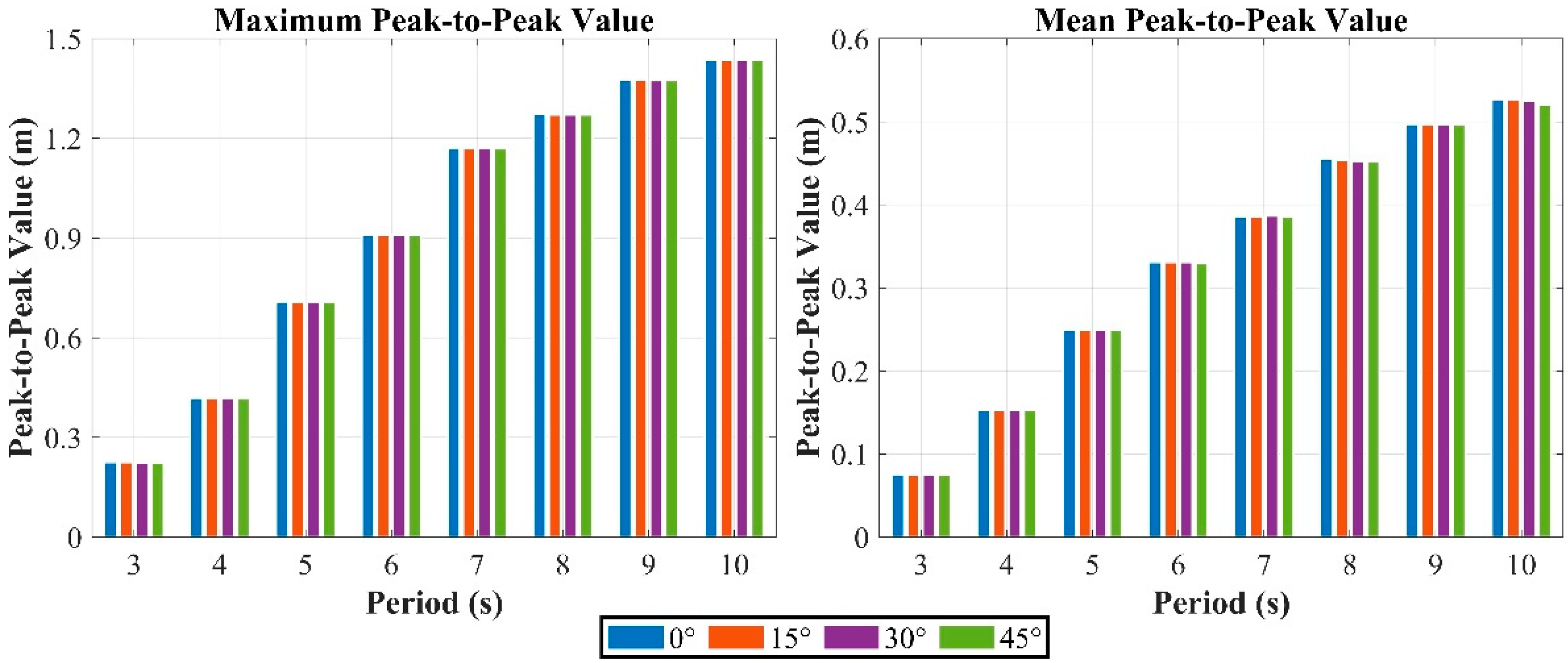
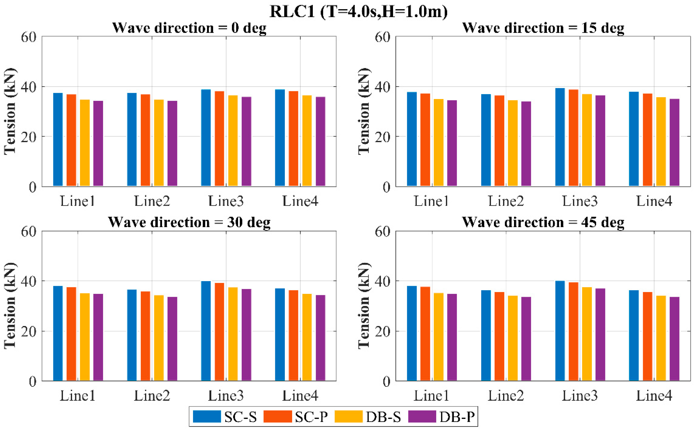
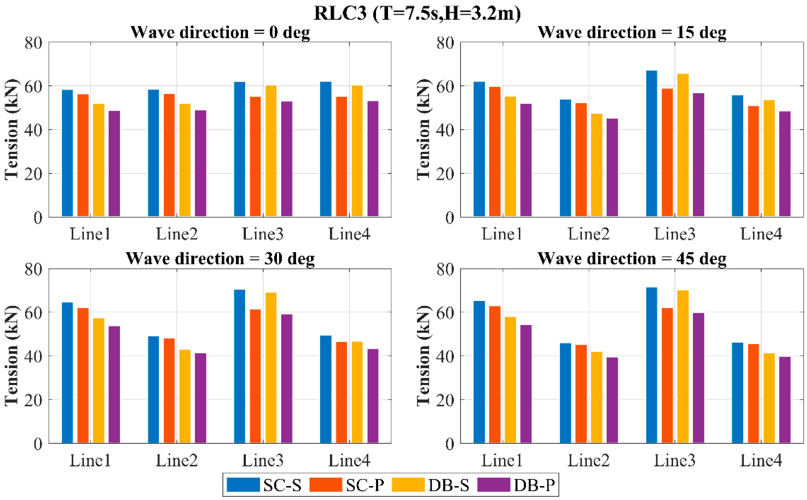
To investigate the mooring line tension characteristics of four two-body WECs,
Figure 23,
Figure 24 and
Figure 25 present the maximum tensions in mooring lines 1–4 for all the WECs under three wave cases at directions of 0°, 15°, 30°, and 45°. The results demonstrate that with increasing sea state severity, the mooring line tensions rise consistently across all directions for each WEC, while the tension differences between WECs significantly diverge.
Across all directions, the SC-S yields maximum mooring line tensions, whereas DB-P gives minimum values. At 0° direction, the tension variations among the four WECs are marginal. With increasing direction, the tensions in lines 1 and 3 rise progressively, while lines 2 and 4 show decreasing values, amplifying the differential between these pairs. Disc-shaped buoys demonstrate lower tensions than simplified configurations across all wave cases and directions. Perforated damping plates generate lower tensions compared to solid plates. The combined use of disc-shaped buoys and perforated damping plates effectively reduces the mooring loads. Collectively, these components reduce the mooring system loads.
4.4. Absorbed Power
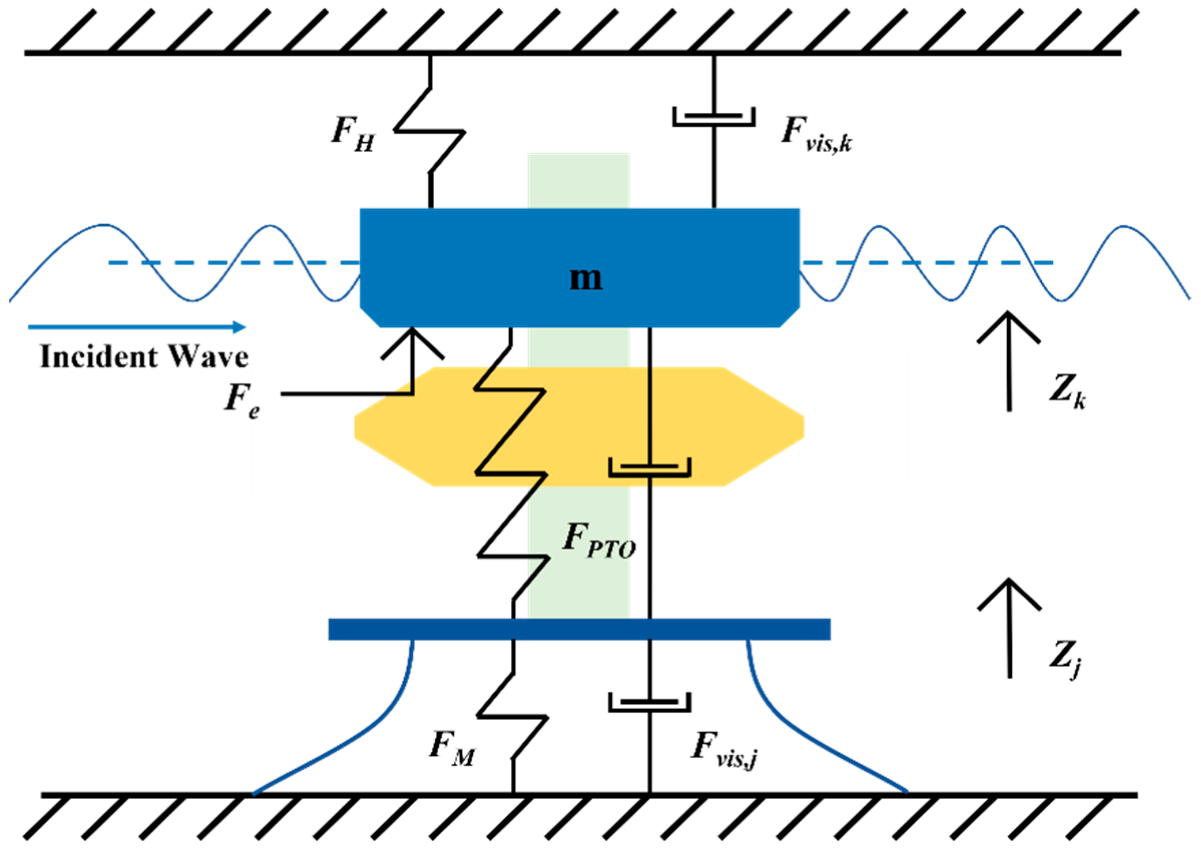
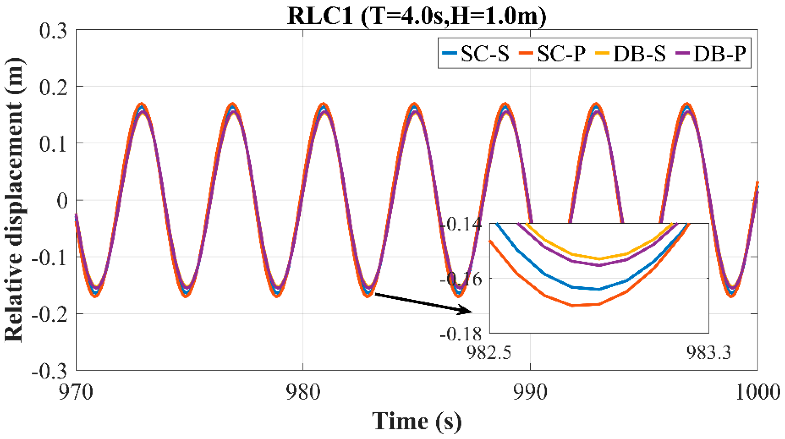
As shown in Equation (9), the power absorption of the WEC depends directly on the relative displacement between the float and the main buoy, and on the magnitude of the PTO damping.
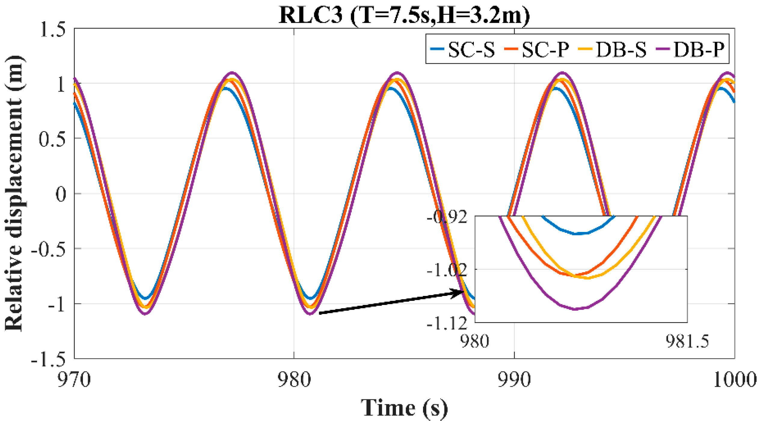
Figure 26,
Figure 27 and
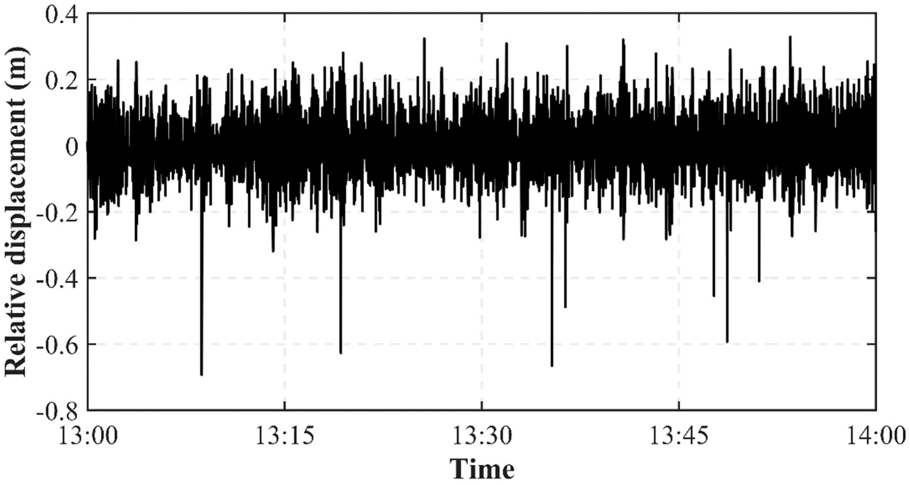
Figure 28 present the simulated relative displacement results for the four WECs in the 0° direction under various wave cases. Due to differences in the motion response among the WECs, their motion amplitudes vary under the same wave case. Therefore, this section accounts for the effect of the motion response in the relative displacement analysis.
As shown in the figure, the peak-to-peak values of the relative displacement increase with increasing wave severity for all four WECs. Under the RLC1 wave case, the SC-P exhibits the largest peak-to-peak value, followed by SC-S, while the DB-S has the smallest value. Under the RLC2 and RLC3 wave cases, DB-P exhibits the largest peak-to-peak value, while SC-S has the smallest. As the wave severity increases, the difference in the peak-to-peak value between SC-P and DB-S gradually decreases. WECs with a perforated damping plate consistently exhibit large relative displacement peak-to-peak values under all three wave cases. Under the RLC1 wave case, WECs with the dish-shaped buoy yield smaller relative displacement peak-to-peak values than those without it. Under the RLC2 and RLC3 wave cases, the presence of the dish-shaped buoy yields larger relative displacement peak-to-peak values than its absence.
Instantaneous power is obtained from the relative displacement between the float and the main buoy, and the PTO damping force. The time-averaged instantaneous power yields the power absorption for the two-body WEC.
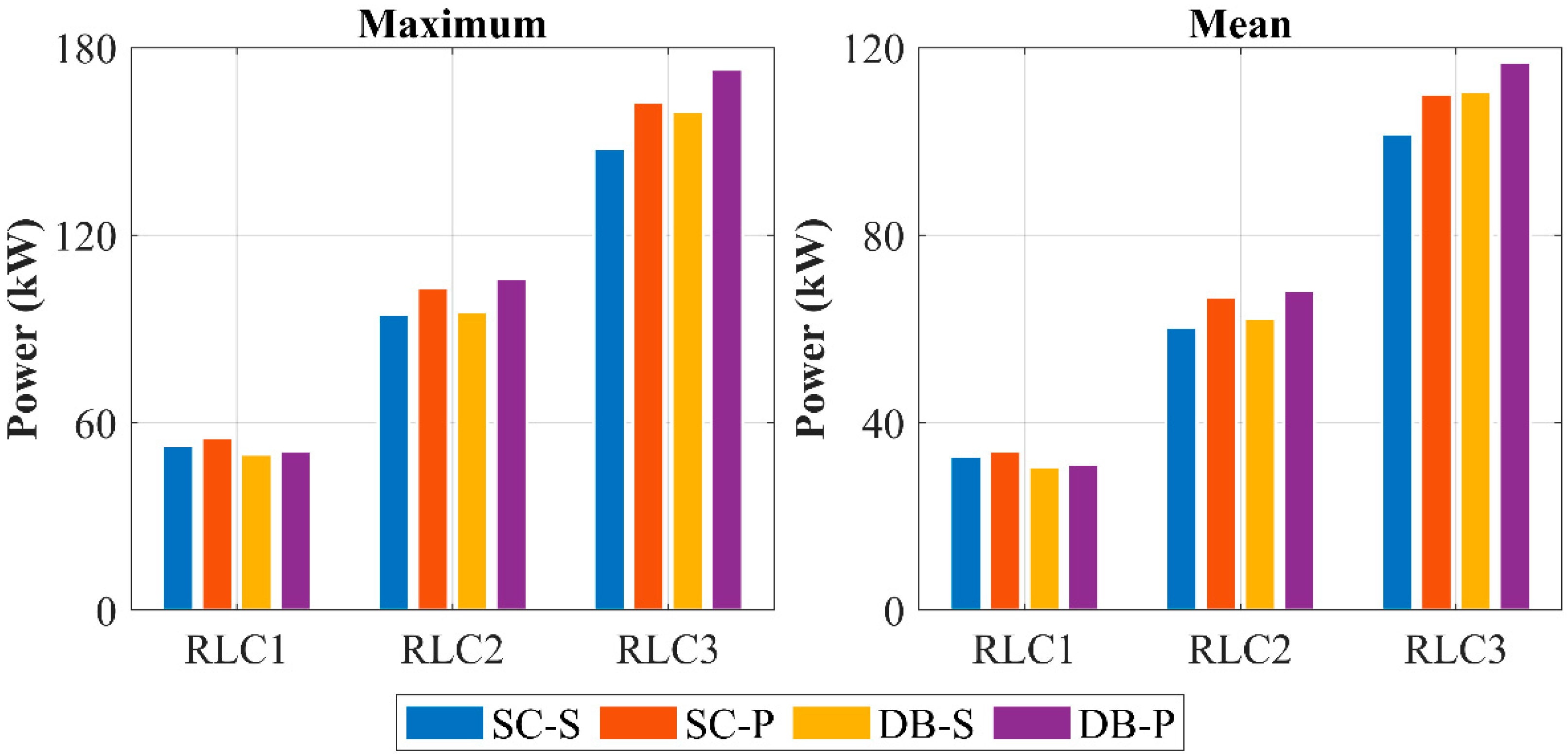
Table 8 and
Figure 29 present the power absorption results for the four WECs under the three regular wave cases. The results indicate that both the average and peak power differ among the WECs across wave cases, and the disparity in power increases with the wave severity. Both the average and peak power exhibit similar trends across the WECs. Under the RLC1 wave case, SC-P achieves the highest power, whereas DB-S yields the lowest. Under the RLC2 and RLC3 wave cases, DB-P and SC-S achieve the highest and lowest power, respectively. WECs with a perforated damping plate consistently yield relatively high mean and peak power under all three wave cases. Under the RLC1 wave case, WECs featuring the dish-shaped buoy achieve lower mean and peak power than those without it. Conversely, under the RLC2 and RLC3 wave cases, the presence of the dish-shaped buoy results in higher mean and peak power compared to its absence.
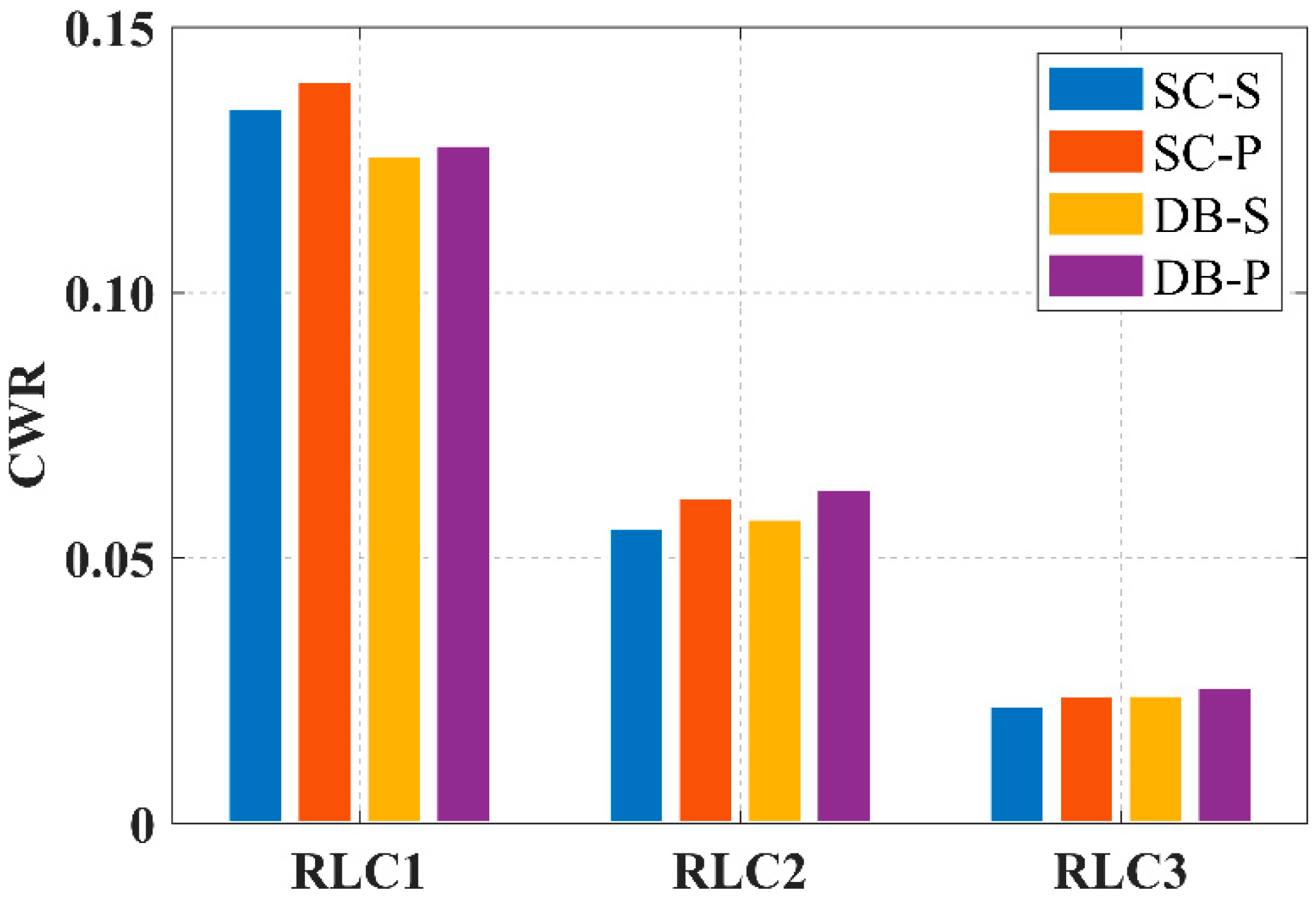
Figure 30 presents the CWR values for the four WECs across wave cases, where the WECs exhibit distinct effects on the CWR. All WECs attain maximum CWR under the RLC1 wave case, with the values declining as the wave severity increases. SC-P yields the maximum CWR under RLC1, whereas DB-P achieves higher CWR under RLC2 and RLC3. WECs with perforated damping plates consistently yield higher CWR, while the dish-shaped buoy enhances the CWR under RLC2 and RLC3 but reduces it under RLC1.
5. Conclusions
This study proposes a novel two-body WEC integrating a dish-shaped buoy with a perforated damping plate. A multi-body coupled hydrodynamic model was developed using potential flow theory, with frequency domain and time domain analyses conducted. Numerical model validation was performed using sea trial data from SDU-III WEC, ensuring model reliability. Four WECs were designed: with or without the dish-shaped buoy and with solid or perforated damping plates. Site-specific numerical simulations assessed the hydrodynamic performance under characteristic wave cases at Tuoji Island. The key findings are summarized as follows.
(1) The dish-shaped buoy significantly enhances the RAO, added mass, radiation damping, and wave excitation force of the WEC in the surge and heave degrees of freedom, while also exhibiting increased added mass in pitch. Regarding the effect of the damping plate porosity, the solid damping plate shows reduced added mass specifically in pitch but generates greater RAO, added mass, radiation damping, and wave excitation forces in surge, heave, and pitch. The dish-shaped buoy and perforated damping plate exhibit enhanced power absorption potential along with superior stability characteristics.
(2) The disc-shaped buoy and perforated damping plate effectively suppress the surge and pitch response peaks of the main buoy, while exhibiting elevated heave response amplitudes, collectively enhancing the device stability.
(3) The disc-shaped buoy and perforated damping plate yield reduced mooring line tensions across four wave incidence angles under three wave cases.
(4) The WEC with a perforated damping plate generates increased peak-to-peak relative displacement, absorbed power, and CWR across all three wave cases. Under smaller wave cases, the disc-shaped buoy reduces the peak-to-peak relative displacement, absorbed power, and CWR compared to the WEC without this buoy, whereas under larger wave cases, it enhances these parameters.
Collectively, this study offers valuable guidance for designing and investigating other two-body WECs. Future work will focus on device optimization through altering the disc-shaped buoy geometry and refining the perforated damping plate porosity distribution. These enhancements are anticipated to boost the overall device performance.
