Article

Nonlinear-Finite-Time-Extended-State-Observer-Based Command Filtered Control for Unmanned Surface Vessels with Rotatable Thrusters Under False Data Injection Attacks

Merchant Marine College, Shanghai Maritime University, Shanghai 201306, China
*
Authors to whom correspondence should be addressed.
These authors contributed equally to this work.
J. Mar. Sci. Eng. 2025, 13(10), 1838; https://doi.org/10.3390/jmse13101838
Submission received: 26 August 2025 / Revised: 17 September 2025 / Accepted: 20 September 2025 / Published: 23 September 2025
(This article belongs to the Section Ocean Engineering)

Abstract

Considering the importance of maritime cybersecurity, this study provides a solution based on a nonlinear finite-time extended state observer (NFTESO) for unmanned surface vessels (USVs) equipped with rotatable thrusters under false data injection attacks (FDIAs). First, to complete the control design for USVs in a network environment and ensure optimal tracking performance within limits, an event triggering mechanism with finite-time constraints and a concise control optimization framework are employed. Then, command filtered technology is applied to obtain the derivative of the virtual control quantity generated using a backstepping design, optimizing the information interaction process in the kinematic and dynamic loops. The design based on the NFTESO estimates the composite uncertain dynamics in the system, including FDIAs, reducing the adverse effects of cyber attacks on the system. Finally, simulation outcomes confirmed the efficacy of the proposed control strategy. The simulation results showed that, compared with two other control schemes, the control scheme designed in this paper improved lateral tracking accuracy by approximately 77.1 % and 94.7 % , and longitudinal tracking accuracy by approximately 95 % and 98 % , respectively. Communication frequency was reduced by approximately 98.82 % and 82.48 % , respectively.

1. Introduction

Over the past decade, the global shipping industry has undergone a significant technological transformation. Traditional, manually operated mechanical systems are gradually being replaced by more complex mechatronic and digital systems [1,2]. The widespread adoption of automated control systems has not only driven the construction of automated ports, but also promoted the development of satellite communications, navigation, and vessel traffic management systems (VTSs). Unmanned surface vessels (USVs), with their flexibility and efficiency, are becoming a crucial vehicle for future maritime cargo transportation. USVs are playing a key role in improving navigation safety, reducing human error, optimizing fuel efficiency, and lowering operating costs. Remote control of USVs relies on the coordinated operation of shore-based control centers, integrated ship-to-shore data links, and satellite communication systems. This collaborative approach is crucial for maintaining stable operations in complex sea conditions and offshore environments [3,4]. However, with the deep integration of unmanned communication technology and intelligent navigation systems, the cybersecurity risks they face are becoming increasingly prominent. Any malicious false data injection attacks (FDIAs) or signal jamming in the communication links involved in critical tasks such as navigation control, cargo scheduling, and collision avoidance decisions can lead to serious navigation deviations, cargo loss, and even maritime accidents. The vulnerability of unmanned communication networks reveals the fragility of ship automation systems. Global maritime safety and the sustainable development of the shipping industry will face huge challenges.
The literature on control issues for USVs under cyberattack is extensive. For example, ref. [5] incorporated signal disruption due to a denial-of-service (DoS) attack into an event-triggered control (ETC) framework to mitigate DoS attack interference. Similarly, ref. [6] developed a resilient adaptive ETC strategy for handling DoS attacks. In [7], auxiliary systems and compensation systems were employed to address the negative effects of actuator constraints and DoS attacks on a system. A method of defending against replay attacks was developed in [8] by transforming an attacked networked control system into a switched system. This reduced the effect of a replay attack on control performance. An efficient adaptive scheme for replay attacks was presented in [9], in which the duration of each replay attack and the subsequent recovery time are carefully analyzed. The scheme defines strict constraints to ensure the stability of the system in complex dynamic environments. FDIAs constitute another common form of attack, in which attackers inject false sensor data or control commands into a system, potentially causing an autonomous USV to deviate from its intended path or even cause a severe accident. Recently, ref. [10] developed a network protection system based on a disturbance observer to effectively estimate the composite uncertainty dynamics of an FDIA. An FDIA defense strategy for USV systems was developed in [11], but this strategy mainly focuses on security at the control end; it does not sufficiently consider security at the communication end during information transmission. Although defense schemes for the communication end were developed in [12,13], these schemes do not completely eliminate the effects of network attacks on a USV’s dynamic loop. Overall, existing research still needs to make breakthroughs in terms of attack type coverage, coordinated protection of both control and communication ends, and robustness in complex environments.
In practice, uncertainty is a major challenge for USVs, even in the absence of network attacks. These uncertainties comprise internal and external uncertainties. Internal uncertainties mainly stem from perturbations in model parameters and the effects of unmodeled dynamics. External uncertainties are attributable to changes in environmental factors, such as wind, wave, and current. The maritime environment is complex, dynamic, and nonlinear, and traditional linear control algorithms are insufficient for this environment and its uncertainty. In this context, advanced control strategies such as adaptive control [14,15], nonlinear feedback [16,17], model predictive control (MPC) [18,19], neural network control [19,20], and disturbance compensation have been widely applied. Several studies [21,22,23] have developed adaptive proportional-integral-derivative control strategies to dynamically adjust the control gain to handle uncertainty in system dynamics. Two studies [24,25] applied a minimal-learning parameter technique based on a neural network framework to produce a concise and efficient control system. To mitigate the loss in accuracy due to vector normalization, refs. [16,17] optimized the system’s control performance by introducing a nonlinear error-driven function. The system’s control performance was further enhanced in [13] by constructing nonlinear components. Although the methods of constructing nonlinear components in [13,16] differed, both proposed techniques are essentially nonlinear feedback control systems. Reference [26] developed an MPC-based collision avoidance decision system for USVs; the system considers both internal and external uncertain dynamics. In [27], a waypoint-based USV path-tracking control strategy using MPC was proposed. An effective method of compensating for internal and external uncertainties in a system was proposed in [28,29] by expanding the functionality of a neural network and disturbance observer. These schemes are all innovative expansions of conventional control strategies and have achieved large improvements in control performance. Although existing research has proposed a variety of advanced control strategies to deal with the internal and external uncertain dynamics of USVs, further breakthroughs are still needed to ensure robustness and real-time performance in highly nonlinear and strong-dynamic environments.
On the basis of the aforementioned studies, this study introduces a control approach aimed at addressing the tracking control challenge of USVs within a network environment. The proposed scheme can handle the effects of FDIAs, input saturation, and both internal and external uncertainties. The principal contributions of this paper are presented as follows:
(1)
A novel scheme is proposed for USVs equipped with rotatable thrusters that are affected by FDIAs in a network environment. Compared with the methods in [4,5,6,7], the scheme improves the information interaction processes in the kinematic and dynamic loops by introducing command filtering to obtain the derivative of the generated virtual control quantity using a backstepping design. This method improves the system’s dynamic response in complex network environments and can effectively address the potential threat of FDIAs.
(2)
A novel nonlinear finite-time extended state observer (NFTESO) is designed. In contrast to the methods in [9,12,13], the NFTESO effectively blocks cyberattacks on the kinematic loop by reconstructing pose information. Moreover, the system extends the methods of [15,17] by using an NFTESO to reconstruct various uncertain dynamics, including for FDIAs, to ensure concise controller expression and effectively suppress complex uncertain dynamics.
(3)
The proposed control scheme is concise and integrates event triggering mechanisms with high-frequency gain at the control end. Compared with the methods in [8,19,20], the approach achieves lower communication bandwidth occupancy and can better suppress interference due to cyberattacks on the vessel control system. This is achieved by periodically adjusting the transmission of control signals, thus optimizing control performance, while maintaining a concise controller structure.

2. System Modeling and Problem Analysis

2.1. Problem Formulation

For control design, a mathematical model with three degrees of freedom is constructed and presented below [30]:
x ˙ = u cos ψ v sin ψ y ˙ = u sin ψ + v cos ψ ψ ˙ = r
u ˙ = 1 m u T τ u + F u + F d u v ˙ = 1 m v F v + F d v r ˙ = 1 m r T τ r + F r + F d r
and
F u = m v v r Y r ˙ r 2 + X u u + X u u u u F v = Y v v + Y | v | v | v | v + Y | r | v | r | v + Y r r m u u r + Y | v | r | v | r + Y | r | r | r | r F r = m u m v u v + Y r ˙ u r + N v v + N r r + N | r | v | r | v + N | v | v | v | v + N | v | r | v | r + N | r | r | r | r
Table 1 provides detailed values of the controller parameters in this scheme.
This paper focuses on an underactuated mathematical model. Therefore, T τ v = 0 .
The input saturation constraints for τ u and τ r are
τ i = sgn τ i , c τ i , max , τ i , c > τ i , max τ i , c , τ i , c > τ i , max , i = u , r
where τ i , max denotes the maximum control force or moment and τ i , c refers to the control command, bounded by input saturation.
To approximate the nonlinear input saturation phenomenon within the control design process, the hyperbolic tangent function is selected:
ς τ i , c = τ i , max tanh τ i , c τ i , max
Following the derivation in [31],
T τ u ς τ u τ u , max 1 tanh 1 : = G u T τ r ς τ r τ r , max 1 tanh 1 : = G r
To incorporate the effects of FDIAs, let
x f = x + μ x y f = y + μ y ψ f = ψ + μ ψ
where u = μ x , μ y , μ ψ T represents the attack signal encountered by a system and N f = x f , y f , ψ f T represents the system’s position after the attack. Several assumptions are made to design the system.
The lemmas required in this paper and the control objective are shown in Figure 1.

2.2. Preliminaries

Definition 1.
A nonlinear system, denoted as x ˙ = f x , x 0 = x o , x Ω 0 R n with state variable x R n , a sphere Ω 0 containing the origin field, and a continuous function f x . Given any initial condition x 0 , there exist a constant > 0 and tuning time function 0 < T x o < such that x t and t T x 0 , the system is semiglobally practically finite-time stable [32,33].
Lemma 1
([34]). For any positive definite Lyapunov function V x with positive scalars ρ, σ and ϖ < 1 satisfying V ˙ ( x ) + ρ V ( x ) + σ V ϖ ( x ) 0 , the nonlinear system in Definition 1 is finite-time stable, and the tuning time satisfies T 1 ρ ( 1 t ) ln ρ V 1 κ x 0 + σ σ .
Lemma 2.
Consider any continuous and smooth function k x = ς * T s x + ε , x Ω defined on a compact set Ω R n . Here, ε represents the approximation error. For all x Ω , one can find a vector ε * > 0 such that ε ε * . s x = exp X c i T X c i ω i 2 serves as the basis function of the neural network. Here, c i is the center of the receptive field, and ω i is the breadth of the Gaussian function. The ideal weight vector ς is unknown and must be estimated [35].
Lemma 3.
For any constant λ > 0 and any scalar ξ R such that 0 ξ ξ 2 ξ 2 + λ 2 1 2 < λ always holds [36].
Lemma 4.
There exist ϑ > 0 and ρ R such that 0 < ρ ρ tanh ρ ϑ 0.2785 ϑ [37].

2.3. Thruster Dynamics

The thrust allocation process of the rotatable thruster is detailed in [13,38]. If the USV is equipped with two rotatable thrusters,
τ u 0 τ r = cos ω 1 cos ω 2 sin ω 1 sin ω 2 l x 1 sin ω 1 l y 1 cos ω 1 l x 2 sin ω 2 l y 1 cos ω 2 ħ 1 h 1 ħ 2 h 2
The extended thrust vector then satisfies
τ u 0 τ r = 1 0 1 0 0 1 0 1 l y 1 l x 1 l y 2 l x 2 ħ 1 x h 1 ħ 1 y h 1 ħ 2 x h 2 ħ 2 y h 2
where ħ 1 = ħ 1 x 2 + ħ 1 y 2 1 2 , ħ 2 = ħ 2 x 2 + ħ 2 y 2 1 2 , ω 1 = atan 2 ħ 1 y , ħ 1 x and ω 2 = atan 2 ħ 2 y , ħ 2 x .

3. Trajectory-Tracking Controller Implementation

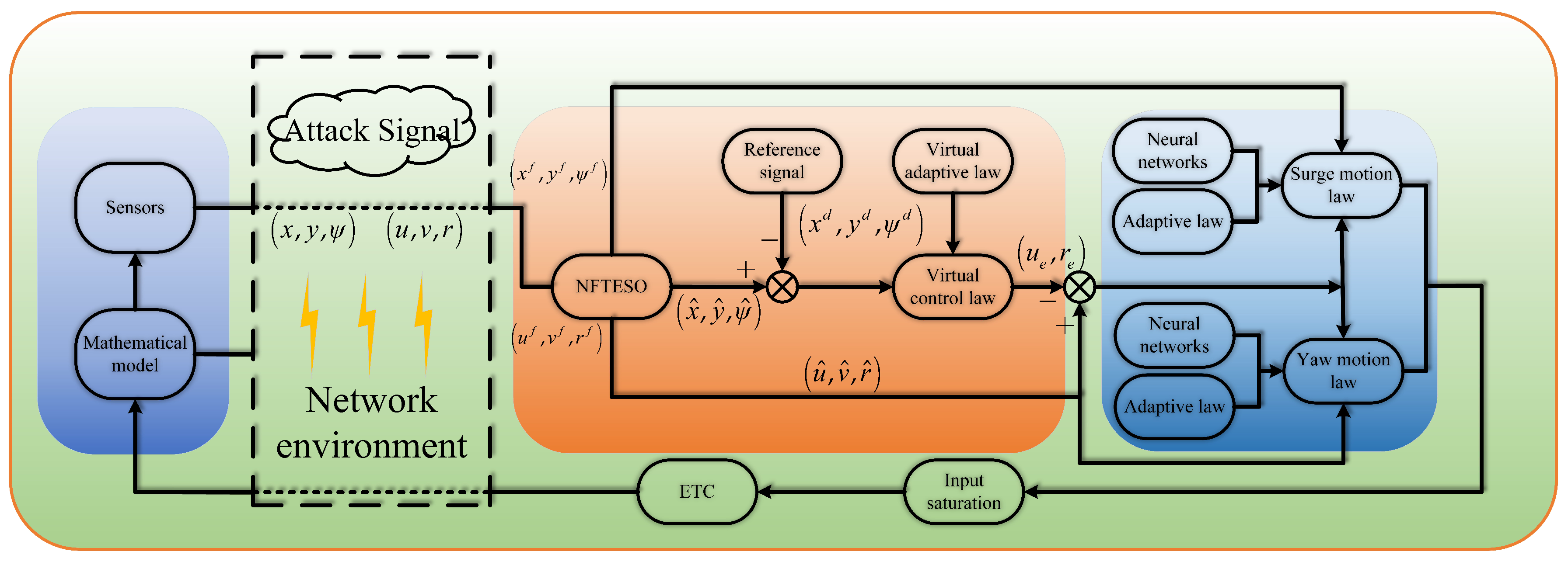
Figure 2 shows the control framework of this paper. Sensors are used to obtain information about the vessel’s motion state. During network transmission, attack signals can cause the observed data to be tampered with. The NFTESO is designed to estimate the disturbed state and, combined with the reference signal, generate a virtual control law. This virtual control law is modified using an adaptive law and interacts with input saturation and the ETC mechanism to achieve stable control under input constraints. Furthermore, neural networks and adaptive techniques are used to further compensate for system uncertainties and nonlinear effects.

3.1. Design of NFTESO

From the mathematical model of the vessel in (1)–(3), the following are obtained:
P ˙ = J ψ υ + μ ˙
P ¨ = J ψ M 1 τ + ϖ
where ϖ = J ˙ ψ υ + J ψ M 1 F d C υ υ D υ υ + μ ¨ is estimated by the NFTESO.
Let ζ 1 = P and ζ 2 = P ˙ . We define the error variables in the following form:
ζ ˜ 1 = ζ 1 ζ ^ 1 ζ ˜ 2 = ζ 2 ζ ^ 2 ζ ˜ 3 = ζ 3 ζ ^ 3
The NFTESO is designed as follows:
ζ ^ ˙ 1 = ζ ^ 2 + α 11 ζ ˜ 1 + α 12 ζ ˜ 1 / ζ ˜ 1 2 + σ x a 1 2 ζ ^ 2 = κ 1 ζ ˜ 1 + χ 1 χ ˙ 1 = ζ ^ 3 + α 21 ζ ˜ 1 + α 22 ζ ˜ 1 / ζ ˜ 1 2 + σ x b 1 2 + J ψ M 1 τ ζ ^ 3 = κ 2 χ 3 + χ 2 χ ˙ 2 = α 31 ζ ˜ 1 + α 32 ζ ˜ 1 / ζ ˜ 1 2 + σ x c 1 2 χ ˙ 3 = ζ ˜ ¨ 1 + α 11 ζ ˜ ˙ 1 + α 12 ζ ˜ ˙ 1 / ζ ˜ 1 2 + σ x a 1 2 + ζ ˜ ˙ 1 + α 11 ζ ˜ 1 + α 12 ζ ˜ 1 / ζ ˜ 1 2 + σ x a 1 2
where x ^ 1 , x ^ 2 and x ^ 1 are the observations of P , P ˙ and ϖ , respectively. α 11 > 0 , α 12 > 0 , α 21 > 0 , α 22 > 0 , α 31 > 0 , α 32 > 0 , σ x a > 0 , σ x b > 0 and σ x c > 0 are design parameters.
By differentiating (12) and substituting (13) into it, we obtain the following:
ζ ˜ ˙ 1 = ζ ˜ 2 α 11 ζ ˜ 1 α 12 ζ ˜ 1 / ζ ˜ 1 2 + σ x a 1 2 ζ ˜ ˙ 2 = ζ ˜ 3 α 21 ζ ˜ 1 α 22 ζ ˜ 1 / ζ ˜ 1 2 + σ x b 1 2 κ 1 ζ ˜ 2 + κ 1 α 11 ζ ˜ 1 + κ 1 α 12 ζ ˜ 1 / ζ ˜ 1 2 + σ x a 1 2 ζ ˜ ˙ 3 = ϖ ˙ α 31 ζ ˜ 1 α 32 ζ ˜ 1 / ζ ˜ 1 2 + σ x c 1 2 κ 2 ζ ˜ 2 κ 2 ζ ˜ 3 + κ 2 α 21 ζ ˜ 1 + κ 2 α 22 ζ ˜ 1 / ζ ˜ 1 2 + σ x b 1 2 + κ 1 κ 2 ζ ˜ 2 κ 1 κ 2 α 11 ζ ˜ 1 κ 1 κ 2 α 12 ζ ˜ 1 / ζ ˜ 1 2 + σ x a 1 2
For the observer, the following Lyapunov function is selected:
L o = 1 2 ζ ˜ 1 T ζ ˜ 1 + 1 2 ζ ˜ 2 T ζ ˜ 2 + 1 2 ζ ˜ 3 T ζ ˜ 3
Taking the derivative of (15) yields the following:
L ˙ o = ζ ˜ 1 T ζ ˜ ˙ 1 + ζ ˜ 2 T ζ ˜ ˙ 2 + ζ ˜ 3 T ζ ˜ ˙ 3 = ζ ˜ 1 T ζ ˜ 2 α 11 ζ ˜ 1 α 12 ζ ˜ 1 / ζ ˜ 1 2 + σ x a 1 2 L ˙ o 1 + ζ ˜ 2 T ζ ˜ 3 α 21 ζ ˜ 1 α 22 ζ ˜ 1 / ζ ˜ 1 2 + σ x b 1 2 κ 1 ζ ˜ 2 + κ 1 α 11 ζ ˜ 1 + κ 1 α 12 ζ ˜ 1 / ζ ˜ 1 2 + σ x a 1 2 L ˙ o 2 + ζ ˜ 3 T ϖ ˙ α 31 ζ ˜ 1 α 32 ζ ˜ 1 / ζ ˜ 1 2 + σ x c 1 2 κ 2 ζ ˜ 2 κ 2 ζ ˜ 3 + κ 2 α 21 ζ ˜ 1 + κ 2 α 22 ζ ˜ 1 / ζ ˜ 1 2 + σ x b 1 2 + κ 1 κ 2 ζ ˜ 2 κ 1 κ 2 α 11 ζ ˜ 1 κ 1 κ 2 α 12 ζ ˜ 1 / ζ ˜ 1 2 + σ x a 1 2 L ˙ o 3
Applying Lemma 3 yields the following inequality:
J ˙ o 1 ζ ˜ 1 T ζ ˜ 2 α 11 ζ ˜ 1 T ζ ˜ 1 + α 12 σ x a α 12 ζ ˜ 1
J ˙ o 2 ζ ˜ 2 T ζ ˜ 3 α 21 ζ ˜ 2 T ζ ˜ 1 + α 22 ζ ˜ 2 T κ 1 ζ ˜ 2 T ζ ˜ 2 + 1 2 κ 1 ζ ˜ 2 T 2 + 1 2 κ 1 α 11 2 ζ ˜ 1 2 + κ 1 α 12 ζ ˜ 2 T
J ˙ o 3 1 10 ζ ˜ 3 T 2 + 5 2 ϖ ˙ 2 + 1 2 α 31 ζ ˜ 3 T 2 + 1 2 α 31 ζ ˜ 1 2 + α 32 ζ ˜ 3 T κ 2 ζ ˜ 3 T ζ ˜ 2 κ 2 ζ ˜ 3 T ζ ˜ 3 + 1 2 κ 2 α 21 ζ ˜ 3 T 2 + 1 2 κ 2 α 21 ζ ˜ 1 2 + κ 2 α 22 ζ ˜ 3 T + 1 2 κ 1 κ 2 ζ ˜ 3 T 2 + 1 2 κ 1 κ 2 ζ ˜ 2 2 + 1 2 κ 1 κ 2 α 11 ζ ˜ 3 T 2 + 1 2 κ 1 κ 2 α 11 ζ ˜ 1 + κ 1 κ 2 α 12 ζ ˜ 3 T
From (17)–(19), the following can be obtained:
J ˙ o α 11 δ a ζ ˜ 1 T ζ ˜ 1 κ 1 δ b ζ ˜ 2 T ζ ˜ 2 κ 2 δ c ζ ˜ 3 T ζ ˜ 3 + 1 4 α 22 + α 22 + κ 1 α 12 + α 32 + κ 2 α 22 + κ 1 κ 2 α 11 + κ 1 κ 2 α 12 α 12 J o + α 12 σ x a + 5 2 ϖ ˙ 2 + α 12 σ x a
Then,
J ˙ o ρ ε a J o ρ ε b J o + σ
where ρ ε a = 2 min α 11 δ a , κ 1 δ b , κ 2 δ c , ρ ε b = α 12 , σ = α 12 σ x a + 5 2 ϖ ˙ 2 + α 12 σ x a + 1 4 α 22 + α 22 + κ 1 α 12 + α 32 + κ 2 α 22 + κ 1 κ 2 α 11 + κ 1 κ 2 α 12 .
The following can be derived from (20):
L ˙ o ƛ ρ ε a L o 1 ƛ ρ ε a L o ρ ε b L o + σ
where 0 < ƛ < 1 . If L o > σ ƛ ρ ε a , then L ˙ o 1 ƛ ρ ε a L o ρ ε b L o . According to Lemma 1, L o can stabilize in the residual set Γ L o = L o : L o σ ƛ ρ ε a within finite time. The settling time is T 4 1 ƛ ρ ε a ln 1 ƛ ρ ε a L o + ρ ε b ρ ε b .

3.2. Design of Tracking Control Law and Stability Analysis

The tracking error variables are defined as follows:
p e = x e y e = x f x d y f y d ψ e = ψ f ψ d
where x d and y d represent the system’s reference positions in the lateral and longitudinal directions, respectively.
Taking the derivative of (23) yields the following:
p ˙ e = x ˙ + μ ˙ x x ˙ d y ˙ + μ ˙ y y ˙ d = Ξ + v ϑ u p ˙ d + u d θ u d + ρ x , y ψ ˙ e = r ψ ˙ d + ρ ψ
where Ξ = u θ u u d θ u d , θ u = cos ψ sin ψ T , θ u d = cos ψ d sin ψ d T , ϑ u = sin ψ cos ψ T , p ˙ d = x ˙ d y ˙ d T and ρ x , y = μ ˙ x μ ˙ y T . The detailed form can be found in (27).
The virtual control laws are specified in the following manner:
o = o u o v = u d θ u d = λ 11 p e λ 12 p e p e 2 + ξ p 2 1 2 v ϑ u + p ˙ d ρ ^ x , y o r = λ 21 ψ e λ 22 ψ e ψ e 2 + ξ ψ 2 1 2 + ψ ˙ d ρ ^ ψ
where λ 11 > 0 , λ 12 > 0 , λ 21 > 0 , λ 22 > 0 , ξ p > 0 and ξ ψ > 0 are design parameters. ρ ^ x , y and ρ ^ ψ are the estimates of ρ x , y and ρ ψ , respectively.
To compensate for false injection attacks, virtual adaptive laws for ρ x , y and ρ ψ are designed as follows:
ρ ^ ˙ x = γ ρ x , y x e θ ρ x , y ρ ^ x ρ ^ ˙ y = γ ρ x , y y e θ ρ x , y ρ ^ y ρ ^ ˙ ψ = γ ρ ψ ψ e θ ρ ψ ρ ^ ψ
where γ ρ x , y > 0 , θ ρ x , y > 0 , γ ρ ψ > 0 and θ ρ ψ > 0 are design parameters.
From (25), the surge reference velocity and heading reference of the system can be derived as follows:
u d = sin ψ d o u + cos ψ d o v 2 sin ψ d cos ψ d ψ d = atan 2 o v , o u
Next, the command filtering technique is applied as follows:
χ ˙ i , 1 = λ n , i χ i , 2 χ ˙ i , 2 = 2 φ i λ n , i χ i , 2 λ n , i χ i , 1 χ i
where λ n , i > 0 , φ i 0 , 1 with i = u , r being design parameters, and χ i , 2 is the state of the command filter; the initial states satisfy χ i , 2 0 = 0 and χ i , 1 0 = χ i 0 .
The new velocity error variables are constructed as follows:
u e = u ^ χ u , 1 r e = r ^ χ r , 1
By differentiating (29) and employing neural networks to reconstruct the system’s dynamic uncertainties, we obtain the following:
m u u ˙ e = ζ u T Θ u υ ^ + τ u + F ξ u m u χ ˙ u , 1 m r r ˙ e = ζ r T Θ r υ ^ + τ r + F ξ r m r χ ˙ r , 1
where F ξ u = F d u + ξ u , F ξ r = F d r + ξ r , and ξ u and ξ r are the approximation errors of the neural network.
The control laws for the tracking system in the closed-loop are as follows:
T u t = λ 31 u e λ 32 u e u e 2 + ξ u 2 1 2 + m u ω ^ ˙ u , 1 ζ ^ u T Θ u υ ^ F ¯ ^ d u tanh u e ξ u T r t = λ 41 r e λ 42 r e r e 2 + ξ r 2 1 2 + m r ω ^ ˙ r , 1 ζ ^ r T Θ r υ ^ F ¯ ^ d r tanh r e ξ r
Moreover, the adaptive laws are as follows:
ζ ^ ˙ u = γ ζ u Θ u υ ^ u e θ ζ u ζ ^ u ζ ^ ˙ r = γ ζ r Θ r υ ^ r e θ ζ r ζ ^ r
F ¯ ^ ˙ d u = γ d u tanh u e ξ u u e θ d u F ¯ ^ d u F ¯ ^ ˙ d r = γ d r tanh r e ξ r r e θ d r F ¯ ^ d r
where λ 31 > 0 , λ 32 > 0 , λ 41 > 0 , λ 42 > 0 , ξ u > 0 , ξ r > 0 , γ ζ u > 0 , γ ζ r > 0 , θ ζ u > 0 , θ ζ r > 0 , γ d u > 0 , γ d r > 0 , θ d u > 0 and θ d r > 0 are design parameters; ζ ^ u , F ¯ ^ d u , ζ ^ r and F ¯ ^ d r are the estimates of ζ u , F ¯ d u , ζ r and F ¯ d r , respectively; F ¯ d u and F ¯ d r are the upper bounds of F d u and F d r , respectively; and ζ ˜ u = ζ u ζ ^ u , ζ ˜ r = ζ r ζ ^ r , F ¯ ˜ d u = F ¯ d u F ¯ ^ d u and F ¯ ˜ d r = F ¯ d r F ¯ ^ d r .
The event triggering mechanisms are defined as follows:
τ u t = T u t k , t t k , t k + 1 t k + 1 = inf t R E u t ϕ u τ u t + o u
τ r t = T r t k , t t k , t k + 1 t k + 1 = inf t R E r t ϕ r τ r t + o r
where ϕ u > 0 , o u > 0 , ϕ r > 0 and o r > 0 are design parameters; E u t = T u t τ u t ; and E r t = T r t τ r t .
For the tracking system, the Lyapunov function is defined in the following form:
L V = L o + 1 2 p e T p e + m u 2 u e 2 + 1 2 γ ρ x , y ρ ˜ x , y T ρ ˜ x , y + 1 2 γ ζ u ζ ˜ u 2 + 1 2 γ d u F ¯ ˜ d u 2 J V 1 + 1 2 ψ e 2 + m r 2 r e 2 + 1 2 γ ρ ψ ρ ˜ ψ 2 + 1 2 γ ζ u ζ ˜ r 2 + 1 2 γ d r F ¯ ˜ d r 2 J V 2
By differentiating (36), we obtain the following:
L ˙ V 1 = p e T p ˙ e + m u u e u ˙ e γ ρ x , y 1 ρ ˜ x , y T ρ ^ ˙ x , y γ ζ u 1 ζ ˜ u ζ ^ ˙ u γ d u 1 F ¯ ˜ d u F ¯ ^ ˙ d u
L ˙ V 2 = ψ e ψ ˙ e + m r r e r ˙ e γ ζ u 1 ζ ˜ r ζ ^ r ˙ γ ρ ψ 1 ρ ˜ ψ ρ ^ ˙ ψ + γ d r 1 F ¯ ˜ d r F ¯ ^ ˙ d r
Substituting (24)–(26), (30), (32), and (33) into (37) yields the following:
L ˙ V 1 λ 11 p e T p e λ 12 p e T p e p e 2 + ξ p 2 1 2 + p e T Ξ + u e ζ u T Θ u υ + u e τ u + u e F ¯ d u m u u e ω ^ ˙ u , 1 ρ ˜ x , y p e θ ρ x , y ρ ^ x , y ζ ˜ u Θ u υ u e θ ζ u ζ ^ u F ¯ ˜ d u tanh u e ξ u u e θ d u F ¯ ^ d u
With reference to Lemmas 3 and 4, substitution of control law (31) into (39) yields
L ˙ V 1 λ 11 0.05 p e T p e λ 31 u e 2 1 4 θ ρ x , y ρ ˜ x , y T ρ ˜ x , y 1 4 θ ζ u ζ ˜ u 2 1 4 θ d u F ¯ ˜ d u 2 + λ 12 ξ p + 5 Ξ 2 λ 12 p e λ 32 0.2785 ξ u u e 1 4 θ ρ x , y ρ ˜ x , y T 1 4 θ ζ u ζ ˜ u 1 4 θ d u F ¯ ˜ d u + λ 32 ξ u + 1 16 θ ρ x , y + 1 2 θ ρ x , y ρ x , y T 2 + 1 16 θ ζ u + 1 2 θ ζ u ζ u 2 + 1 16 θ d u + 1 2 θ d u F ¯ d u 2
Substituting (24)–(26), (30), (32), and (33) into (38) yields the following:
L ˙ V 2 λ 21 ψ e 2 λ 12 ψ e 2 ψ e 2 + ξ ψ 2 1 2 + ψ e r e + ψ e ρ ˜ ψ + r e ζ r T Θ r υ + r e τ r + r e F ¯ d r m r r e ω ^ ˙ r , 1 ζ ˜ r Θ r υ r e θ ζ r ζ ^ r ρ ˜ ψ ψ e θ ρ ψ ρ ^ ψ F ¯ ˜ d r tanh r e ξ r r e θ d r F ¯ ^ d r
Further simplifying (41) yields
L ˙ V 2 λ 21 0.5 ψ e 2 λ 41 0.5 r e 2 1 4 θ ρ ψ ρ ˜ ψ 2 1 4 θ ζ r ζ ˜ r 2 1 4 θ d r F ¯ ˜ d r 2 λ 12 ψ e λ 42 0.2785 ξ r r e 1 4 θ ρ ψ ρ ˜ ψ 1 4 θ ζ r ζ ˜ r 1 4 θ d r F ¯ ˜ d r + λ 12 ξ ψ + λ 42 ξ r + 1 16 θ ζ r + 1 2 θ ζ r ζ r 2 + 1 16 θ ρ ψ + 1 2 θ ρ ψ ρ ψ 2 + 1 16 θ d r + 1 2 θ d r F ¯ d r
From (22), (40), and (42), we obtain the following:
L ˙ V a L V b L V 1 2 + Ξ p
where a = 2 min λ 11 1 2 , λ 31 , 1 4 θ ρ x , y , 1 4 θ ζ u , 1 4 θ d u , λ 21 0.5 , λ 41 0.5 , 1 4 θ ρ ψ , 1 4 θ ζ r , 1 4 θ d r , ρ ε a , b = 2 min λ 12 , λ 32 0.2785 ξ u , 1 4 θ ρ x , y , 1 4 θ ζ u , 1 4 θ d u , λ 12 , λ 42 0.2785 ξ r , 1 4 θ ρ ψ , 1 4 θ ζ r , 1 4 θ d r , ρ ε b , Ξ p = λ 12 ξ p + 5 Ξ 2 + λ 32 ξ u + 1 16 θ ρ x , y + 1 2 θ ρ x , y ρ x , y T 2 + 1 16 θ ζ u + 1 2 θ ζ u ζ u 2 + 1 16 θ d u + 1 2 θ d u F ¯ d u 2 + λ 12 ξ ψ + λ 42 ξ r + 1 16 θ ζ r + 1 2 θ ζ r ζ r 2 + 1 16 θ ρ ψ + 1 2 θ ρ ψ ρ ψ 2 + 1 16 θ d r + 1 2 θ d r F ¯ d r .
Theorem 1.
Under Assumptions 1–5, for USVs subject to dynamic uncertainties, external disturbances, input saturation, and cyberattacks, a novel control method based on an NFTESO is adopted on the basis of the vessel model (1)–(3). The closed-loop tracking system possesses the following properties:
(1) 
The actual trajectory p d = x d , y d T of the vessel can follow the reference trajectory p d = x d , y d T , and the trajectory tracking errors x e and y e converge to a compact set Ω L V = p e R p e 2 Ξ p λ a , 0 < ƛ < 1 within finite time.
(2) 
All signals in the closed-loop tracking system remain bounded.
(3) 
Under the event triggering mechanisms (34) and (35), Zeno behavior can be avoided.
Proof. 
(1)
From (43), we obtain the following:
L ˙ V λ a L V 1 λ a L V b L V 1 2 + Ξ p
If L V > Ξ p λ a , then
L ˙ V 1 λ a L V b L V 1 2
According to Lemma 1, L V can stabilize within the residual set Ω L V = L V : L V Ξ p λ a within finite time and with a settling time of
T 4 1 λ a ln 1 λ a L V 0 + b b
where L V 0 is the initial value of L V .
From (36), we can deduce that 1 2 p e T p e L V 2 Ξ p λ a ; that is,
Ω J V = p e R p e 2 Ξ p λ a
(2)
From (44), we obtain L ˙ V a L V + Ξ p , which indicates that L V is bounded. Next, (36) indicates that p e , ψ e , u e , r e , ζ ˜ u , ζ ˜ r , ρ ˜ x , y , ρ ψ ˜ , F ¯ ˜ d u , F ¯ ˜ d r , ζ ˜ 1 , ζ ˜ 2 and ζ ˜ 3 are all bounded. According to assumptions 3 and 5, we can conclude that x, x f , y, y f , ψ and ψ f are bounded. Because x f , y f , ψ f and ζ ˜ 1 are bounded, ζ ^ 1 is bounded. According to assumption 5 and the boundedness of ρ ˜ x , y and ρ ˜ ψ , we can conclude that ρ ^ x , y and ρ ^ ψ are bounded. Then, the boundedness of ω and ω r can be derived from the boundedness of ρ ^ x , y , ρ ^ ψ , p e , and ψ e . Furthermore, because ω , ω r , u e and r e are bounded, it follows that u ^ and r ^ are bounded. According to assumption 4 and the boundedness of u ^ and r ^ , we conclude that u, v and r are bounded and further deduce that ζ ^ 2 is bounded. The boundedness of ζ ^ 3 can then be derived from the boundedness of ϖ and ζ ˜ 3 . Considering the properties of Θ u υ ^ and Θ r υ ^ and the boundedness of u ^ , v ^ and r ^ , we can conclude that Θ u υ ^ and Θ r υ ^ are bounded. According to Assumption 2 and the boundedness of F ¯ ˜ d u and F ¯ ˜ d r , the terms F ¯ ^ d u and F ¯ ^ d r are bounded. Furthermore, the control laws L u t and L r t must be bounded. It follows that every signal in the closed-loop tracking system is bounded.
(3)
According to the event triggering mechanisms (34) and (35), τ u and τ r are constant values within the time interval t t k , t k + 1 . Differentiating the measurement error yields the following:
d E u t d t = d d t E u t E u t 1 2 = sgn E u t E ˙ u t L ˙ u d E r t d t = d d t E r t E r t 1 2 = sgn E r t E ˙ r t L ˙ r
From (31), it follows that
T ˙ u t = λ 31 u ˙ e u e 2 + ξ u 2 1 λ 32 u ˙ e u e 2 + ξ u 2 1 2 λ 32 u e u e u e 2 + ξ u 2 1 2 sgn u e u ˙ e + m u ω ^ ¨ u , 1 ζ ^ ˙ u T Θ u υ ζ ^ u T Θ ˙ u υ F ¯ ^ ˙ d u tanh u e ξ u F ¯ ^ d u cos 2 u e ξ u u ˙ e
T ˙ r t = λ 41 r ˙ e r e 2 + ξ r 2 1 λ 42 r ˙ e r e 2 + ξ r 2 1 2 λ 42 r e r e r e 2 + ξ r 2 1 2 sgn r e r ˙ e + m r ω ^ ¨ r , 1 ζ ^ ˙ r T Θ r υ ζ ^ r T Θ ˙ r υ F ¯ ^ ˙ d r tanh r e ξ r F ¯ ^ d r cosh 2 r e ξ r r ˙ e
Given that all signals within the closed-loop tracking system are bounded, there exist constants u and r such that T ˙ u u and T ˙ r r . When E u t = 0 and E r t = 0 , it follows that lim t t k + 1 E u t = φ u τ u + o u and lim t t k + 1 E r t = φ r τ r + o r . Therefore, there exists a time interval t such that t u φ u τ u + o u u and t r φ r τ r + o r r . Thus, Zeno behavior can be avoided.
In conclusion, Theorem 1 is proven. □
Remark 1.
Finite-time techniques enable rapid convergence and accurate estimation within a finite-time. Their computational complexity stems primarily from nonlinear operators such as fractional powers and sign functions. This can present implementation challenges in resource-constrained airborne systems. However, compared to model predictive control that relies on optimization, this approach offers a more analytical structure and limited overhead, making it more suitable for real-time applications.

4. Simulation Results and Discussion

Details of the dynamic parameters employed in the simulation model can be found in [39]. A simulation was carried out with the system initialized at x 0 , y 0 , ψ 0 , u 0 , v 0 , r 0 T = 0 , 3 , 0 , 0 , 0 , 0 T . The simulation duration was 200 s with a time step of 0.01 s. The input saturation limits were defined as follows: τ u = 10 N , τ r = 10 N . m The simulation disturbance terms of the system were set as follows: F d u = 0 . 2 1 + 0.3 sin 0.2 t + 0.1 cos 0.3 t , F d v = 0.3 1 + 0.2 sin 0.2 t + 0.2 cos 0.3 t and F d r = 0 . 3 1 + 0.2 sin 0.1 t + 0.3 cos 0.2 t . The FDIA signals were set as follows: μ x = 0.1 sin 0.2 t cos 0.03 t , μ y = 0.2 sin 0.1 t cos 0.02 t and μ ψ = 0.15 sin 0.15 t cos 0.01 t . The dynamic equation of the reference trajectory was set as x d = 30 sin 0.01 π t + 0.01 π t and y d = 30 30 cos 0.01 π t + 6 sin 0.02 π t . The parameter values of the control law are provided in Table 2.
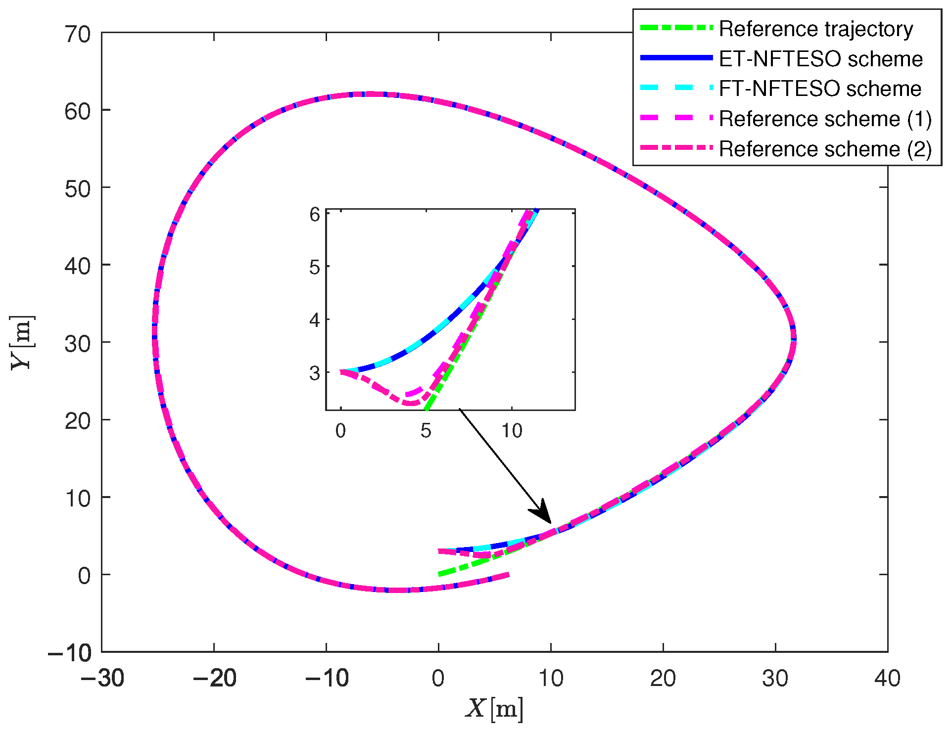
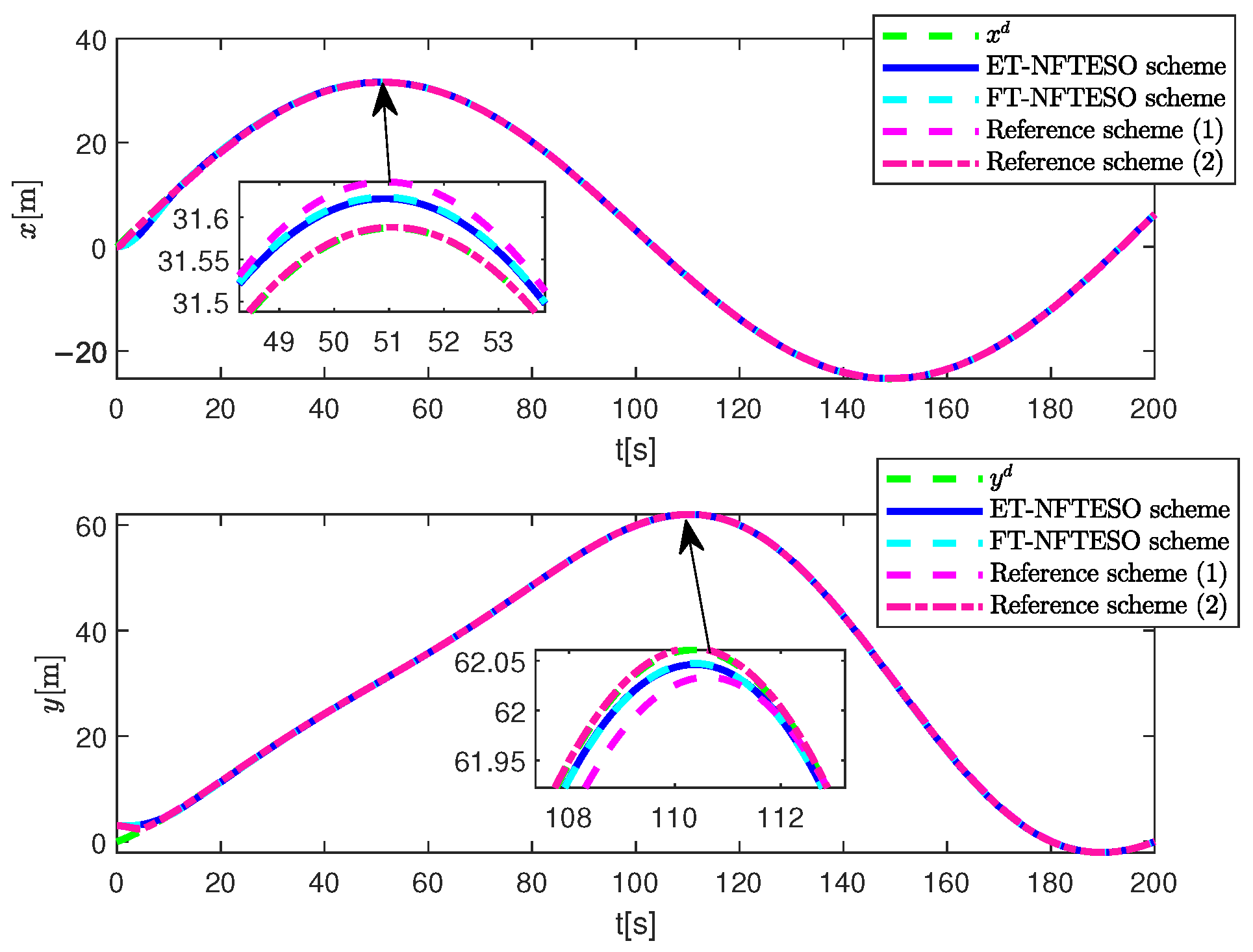
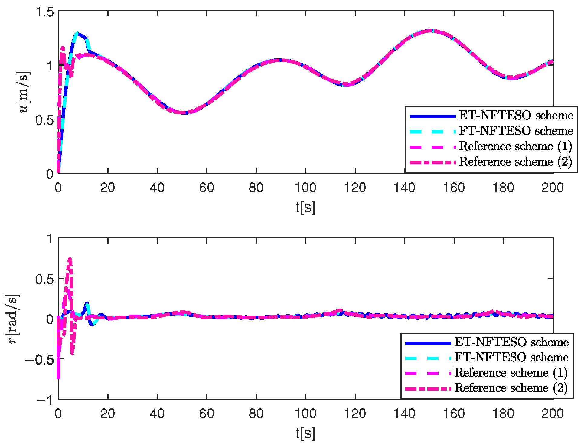
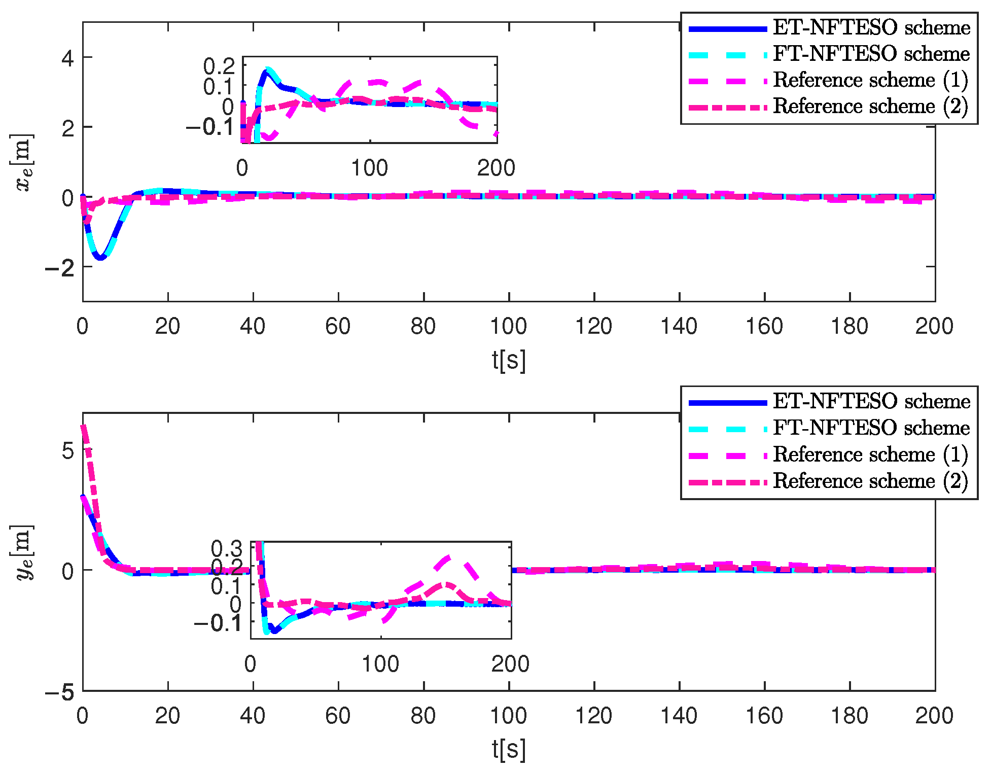
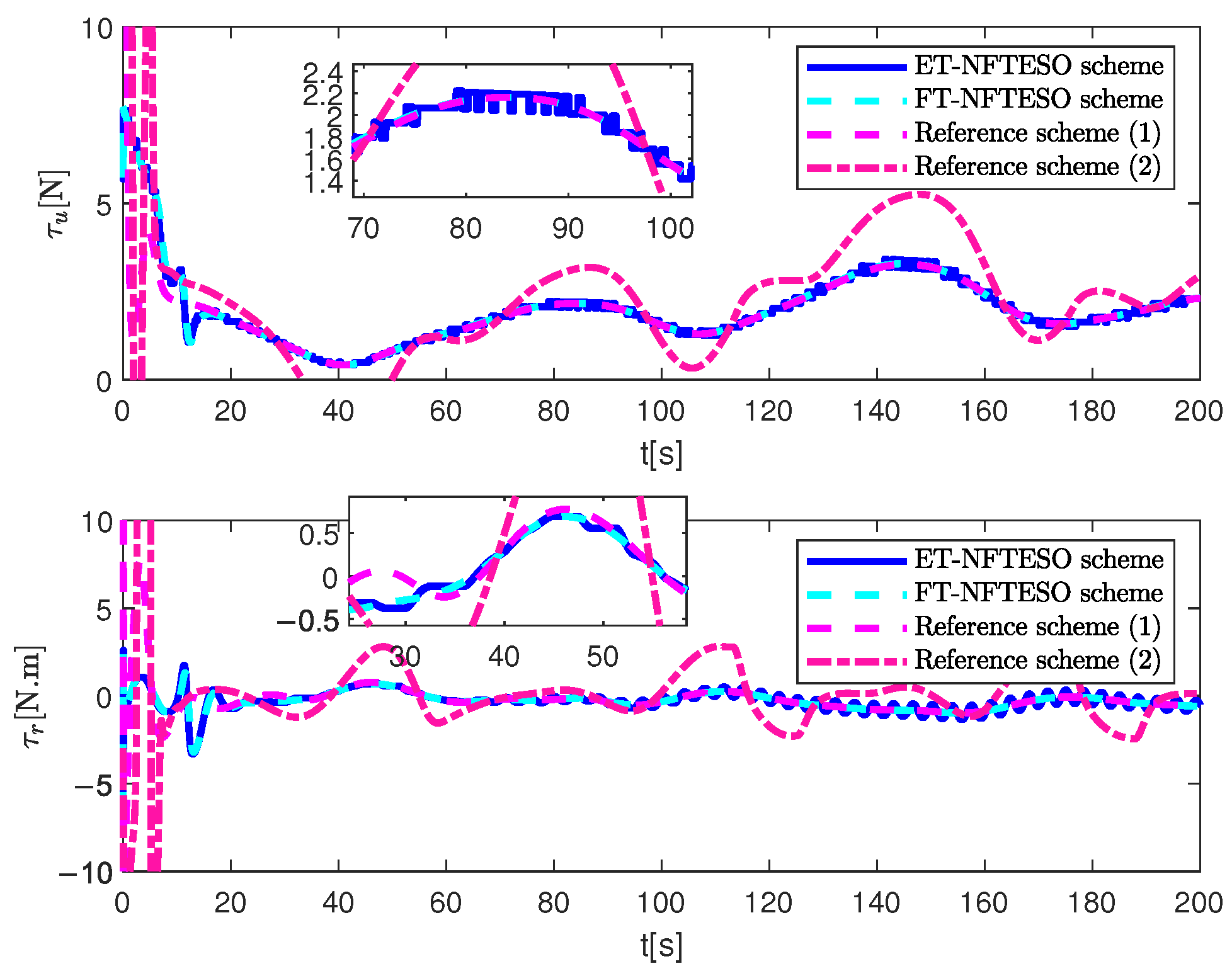
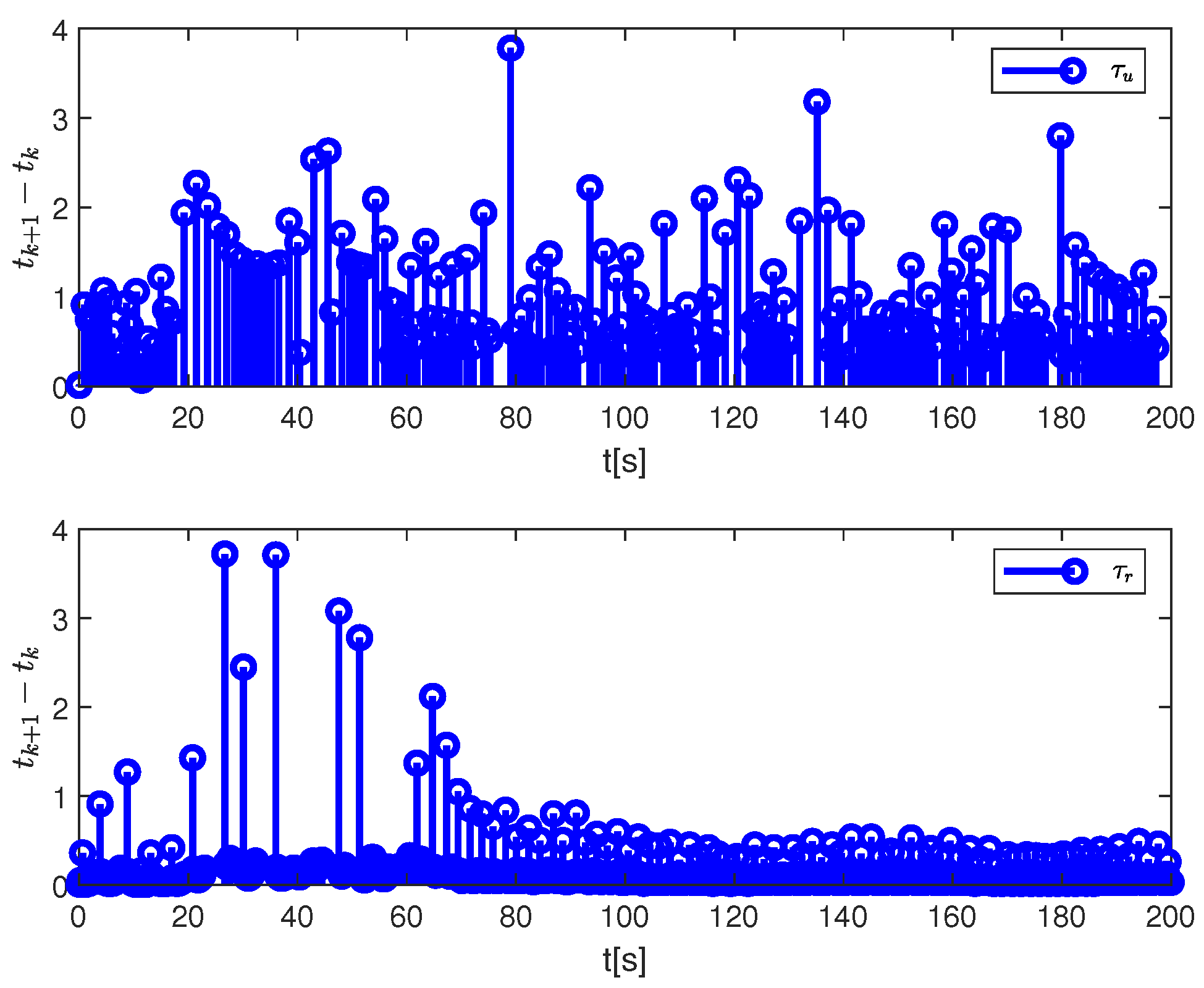
Figure 3, Figure 4, Figure 5, Figure 6, Figure 7, Figure 8, Figure 9, Figure 10, Figure 11, Figure 12, Figure 13 and Figure 14 present the simulation results of the proposed control schemes. Figure 3 and Figure 4 show the tracking performance of the ship under the two control schemes designed in this section. Both control schemes enabled the vessel to track the reference signal with satisfactory tracking performance. The velocity time curve in Figure 5 shows that the system velocity tended to stabilize over time. Figure 6 plots the system tracking error time curve. Despite the influence of cyber attacks, internal and external uncertainties, and input saturation, the vessel maintained high tracking accuracy. As can be seen from the figures, the lateral error of the NFTESO command-filtered control with event-triggered input scheme (ET-NFTESO scheme) and the continuous-time NFTESO command-filtered control scheme (FT-NFTESO scheme) converged around the 12th second, and the control accuracy ultimately stabilized at around 0.008m. The longitudinal error converged around the 12th second, and the control accuracy ultimately stabilized at around 0.005 m. Figure 7 and Figure 8 show the time curves of the control input and thrust. They were both bounded and reasonable, and no Zeno phenomenon occurred.
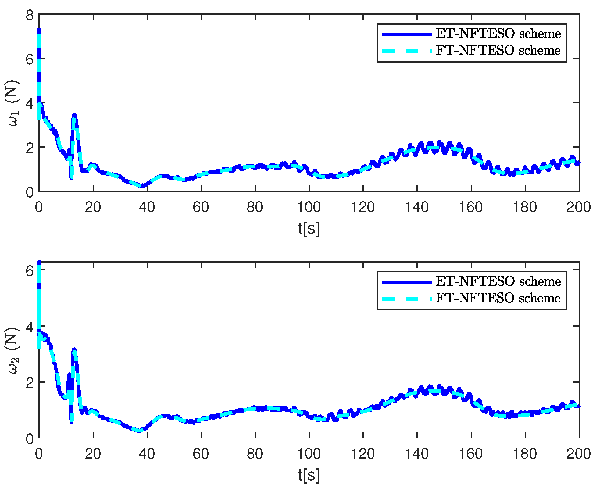
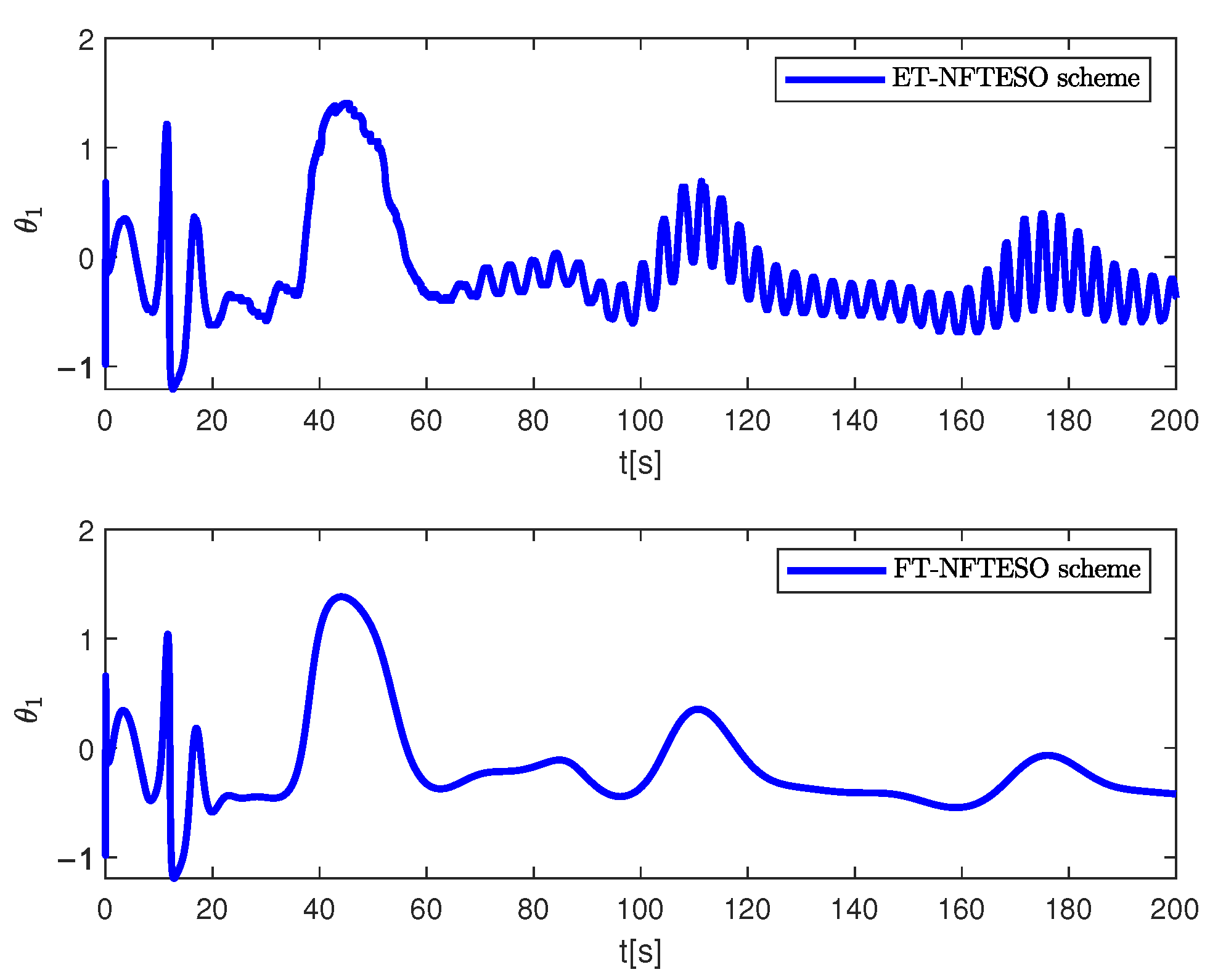
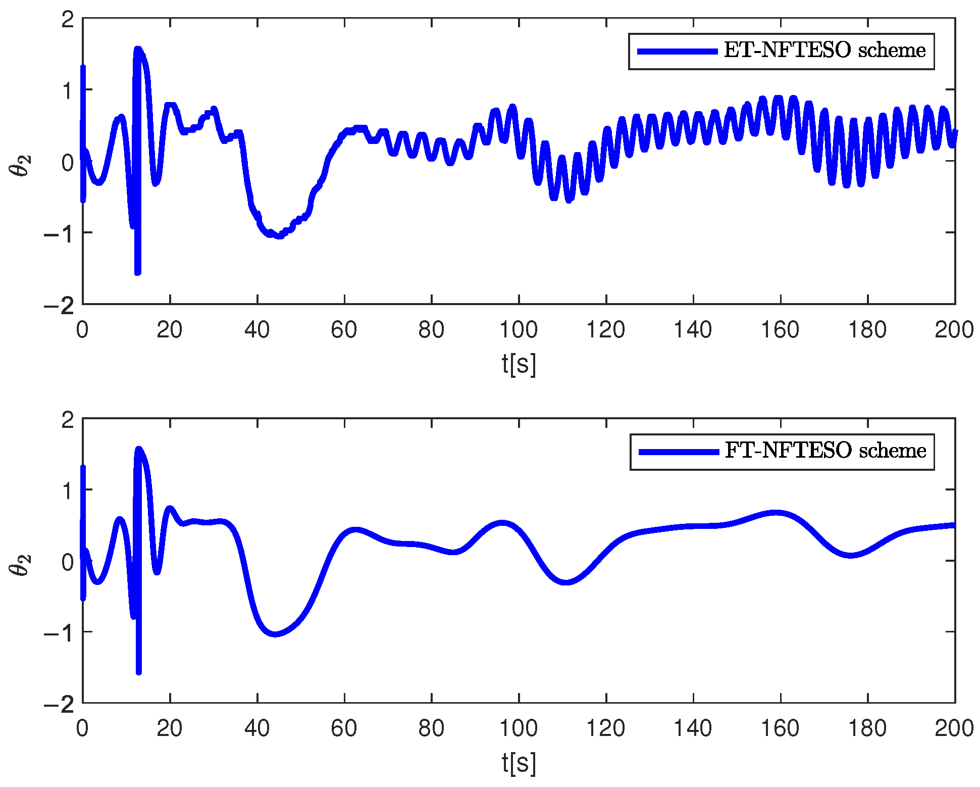
Figure 9 and Figure 10 show the time course curves of the propeller rotation angle. The results show that both the ET-NFTESO and FT-NFTESO schemes had large initial oscillation amplitudes. However, over time, the oscillation amplitudes gradually decayed and stabilized. Compared to the ET-NFTESO scheme, the FT-NFTESO scheme decayed more rapidly. Within the set simulation time period, the fluctuations in the rotation angle of the FT-NFTESO scheme tended to be smaller, demonstrating better stability.
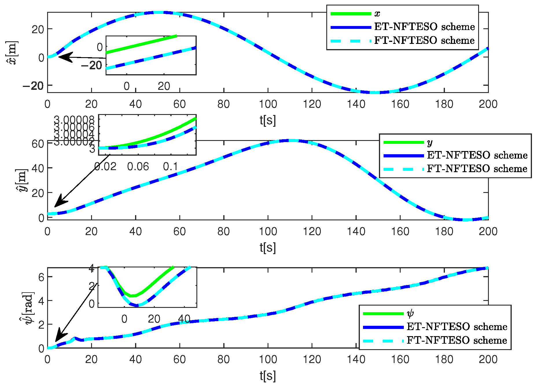
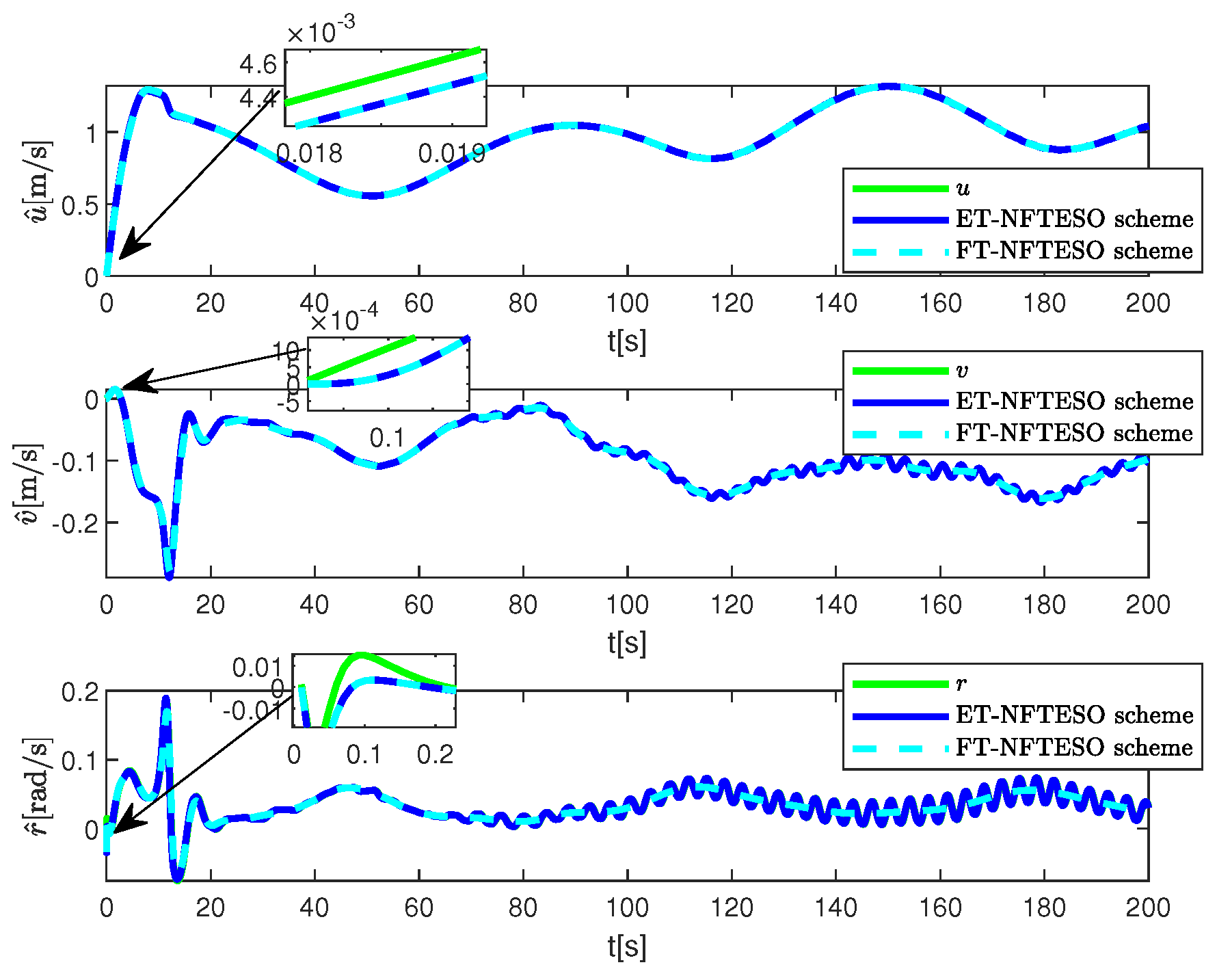
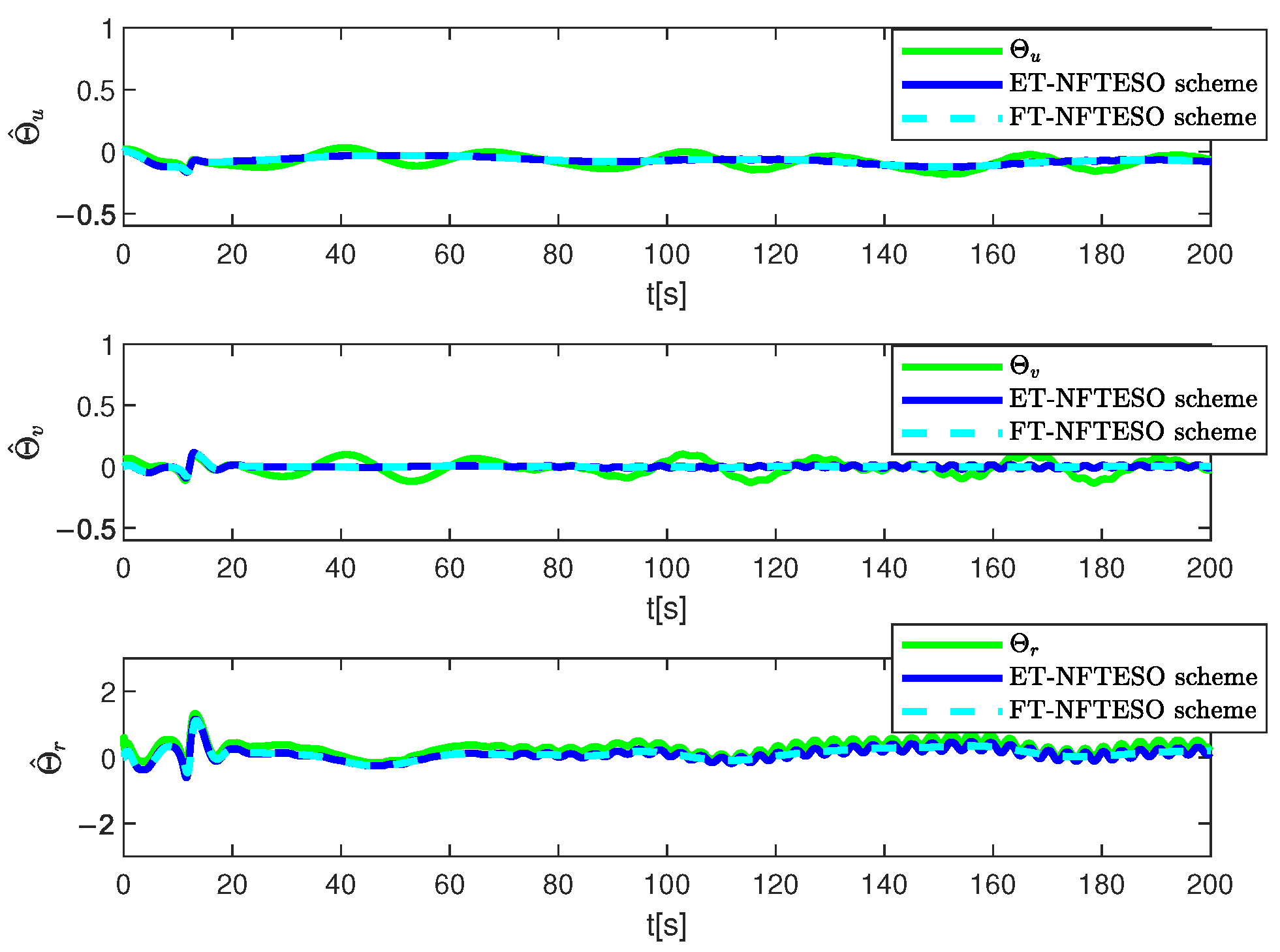
Figure 12, Figure 13 and Figure 14 show the estimated curves of the extended state observer. It can be seen that the observer’s estimated values are highly consistent with the actual values. The finite-time extended observer designed in this section effectively estimated the various velocity components and composite disturbances of the ship system. Furthermore, the estimated results of the observers under the two different schemes are largely consistent, demonstrating the reliability of the two schemes designed in this paper.
To further verify the effectiveness of the control scheme designed in this section, we compared it with the cyber attack control schemes in [1,11]. The control law in [1] is given by Equations (51) and (52) (Reference scheme (1)). The control law in [11] is given by Equations (53)–(55) (Reference scheme (2)).
τ u = λ 12 S 12 f 12 Ω ^ 21 A u 2 σ S 12 τ r = λ 22 S 22 f 22 Ω ^ 22 A r 2 σ S 22
Ω ^ ˙ 12 = f 12 A u 2 σ S 12 2 σ 12 Ω ^ 12 Ω ^ ˙ 22 = f 22 A r 2 σ S 22 2 σ 22 Ω ^ 22
where Ω 21 and Ω 22 characterize the composite uncertain dynamics. A u σ and A r σ originate from parameter decomposition. λ 12 , λ 22 , f 21 , f 22 , σ 12 and σ 22 function as design variables.
τ u = η 31 u e η 32 s i g υ u e Θ ^ u ξ ^ d u z e cos φ e + m u β ˙ u τ r = η 41 r e η 42 s i g υ r e Θ ^ r ξ ^ d r φ e + m r β ˙ r
Θ ^ ˙ u = μ u tanh u e δ ϑ u u e ϑ u Θ ^ u Θ ^ ˙ r = μ r tanh r e δ ϑ r r e ϑ r Θ ^ r
ξ ^ ˙ d u = ε u tanh u e δ ϕ u u e ϕ u ξ ^ d u ξ ^ ˙ d r = ε r tanh r e δ ϕ r r e ϕ r ξ ^ d r
where η 31 , η 32 , μ u , ϑ u , δ ϑ u , ε u , ϕ u , δ ϕ u , η 41 , η 42 , μ r , ϑ r , δ ϑ r , ε r , ϕ r and δ ϕ r are positive definite parameters. Θ ^ u , Θ ^ r , ξ ^ d u and ξ ^ d r are the estimated values of Θ u , Θ r , ξ d u and ξ d r .
Figure 3, Figure 4 and Figure 6 and Table 3 show the tracking effects of the three control schemes. Among them, the response speed of the comparison scheme seemed to be faster. However, as time goes by, the tracking progress of the two control schemes designed in this paper was significantly better than the two comparison schemes. According to the performance index comparison in Table 3, the two control schemes designed in this paper showed superior control performance, followed by the control scheme in reference [11], and finally the control scheme in reference [1]. Compared with the control schemes in reference [11] and reference [1], the ET-NFTESO scheme demonstrated an improvement of about 74.1 % and 94.7 % in lateral tracking accuracy and about 95 % and 98 % in longitudinal tracking accuracy. The ET-NFTESO scheme was affected by the event-triggered protocol, and some control instructions were lost to varying degrees during the transmission process. Therefore, the tracking accuracy of the FT-NFTESO scheme was slightly higher than that of the ET-NFTESO scheme. However, it can be seen from Figure 7 and Figure 11 that the update frequency of the controller was significantly reduced. The update times of the ET-NFTESO scheme controller were 236 and 3503 times, respectively. The maximum trigger time was about 3.8 s and 3.7 s, respectively. Compared with the other three control schemes, communication resources were saved by about 98.82 % and 82.84 % . The above results show that all signals in the closed-loop trajectory tracking control system were bounded and no Zeno behavior occurred.
Remark 2.
In the control scheme designed in this paper, the sensitivity of parameters to system performance is primarily reflected in the attack intensity, disturbance amplitude, and the settings of the controller and observer gains. First, when the amplitude or frequency of the spurious injection attack changes, the finite-time state observer can rapidly reconstruct the state within a finite time, thereby ensuring the convergence of the observation error. However, if the attack signal is too intense, this may cause significant jitter in the observer during the transient phase, thus affecting control performance. Furthermore, changes in external disturbances can affect the system’s convergence speed and steady-state accuracy. When the control gain is inconsistent, the error convergence time may be prolonged. The controller parameter settings have a direct impact on the system’s robustness: while larger gains can accelerate convergence, they may cause actuator saturation or chattering; smaller gains weaken the ability to suppress attacks and disturbances. Therefore, while this scheme demonstrates excellent control performance overall, there are still some differences in convergence speed and control performance under different parameter conditions.

5. Conclusions

This work developed an FTESO-based control scheme to solve the tracking problem of USVs with rotatable thrusters under FDIA conditions. In the control design, a finite-time constrained event triggering mechanism is combined with a concise control optimization framework to achieve efficient control and optimization of USV tracking performance. Through the application of command filtering techniques, the interaction process for the information in the kinematic and dynamic loops is optimized, ensuring the accuracy of the derivative of the virtual control law. The NFTESO can successfully estimate the composite uncertain dynamics in the system, effectively reducing the effect of an FDIA on the system. The ETC method in the scheme reduces the required communication resources, without greatly decreasing performance. Finally, simulation results verified the effectiveness of the proposed control scheme in a complex network environment. In the future, we hope to introduce more complex attack types and build a physical experimental platform to provide more complex and practical verification of the control scheme. Furthermore, we hope to build upon the three-degree-of-freedom mathematical model and introduce more complex controlled objects and application scenarios.

Author Contributions

M.C.: writing the manuscript, carrying out experiments, data analyzing; G.Z. and X.M.: conceptualization, methodology, supervision, data processing, editing figures. All authors reviewed the manuscript. All authors have read and agreed to the published version of the manuscript.

Funding

The authors would like to acknowledge the National Natural Science Foundation of China (NSFC51779136).

Data Availability Statement

No new data were created or analyzed in this study.

Conflicts of Interest

The authors declare that there are no conflicts of interest with any institutions or individuals. All authors consent to submit this manuscript to Journal of Marine Science and Engineering.

References

  1. Wu, C.; Zhu, G.B.; Lu, J.S. Indirect adaptive neural tracking control of USVs under injection and deception attacks. Ocean. Eng. 2023, 270, 113641. [Google Scholar] [CrossRef]
  2. Karimi, M.H.R.; Lu, Y.Y. Guidance and control methodologies for marine vehicles: A survey. Control Eng. Pract. 2021, 111, 104785. [Google Scholar] [CrossRef]
  3. Wang, N.; Zhang, Y.H.; Ahn, C.K.; Xu, Q.Y. Autonomous Pilot of Unmanned Surface Vehicles: Bridging Path Planning and Tracking. IEEE Trans. Veh. Technol. 2022, 71, 2358–2374. [Google Scholar] [CrossRef]
  4. Lu, Y.; Su, R.; Zhang, C.X.; Qiao, L. Event-Triggered Adaptive Formation Keeping and Interception Scheme for Autonomous Surface Vehicles Under Malicious Attacks. IEEE Trans. Ind. Inform. 2022, 18, 3947–3957. [Google Scholar] [CrossRef]
  5. Jiang, C.Y.; Zhang, G.Q.; Huang, C.F.; Zhang, W.J. Memory-based event-triggered path-following control for a USV in the presence of DoS attack. Ocean. Eng. 2024, 310, 118627. [Google Scholar] [CrossRef]
  6. Xie, X.H.; Hu, S.L.; Liu, Y.G.; Li, Q.X. Resilient Adaptive Event-Triggered H8 Fuzzy Filtering for Cyber-Physical Systems Under Stochastic-Sampling and Denial-of-Service Attacks. IEEE Trans. Fuzzy Syst. 2023, 31, 278–292. [Google Scholar] [CrossRef]
  7. Luo, P.; Wu, D.F.; Yamashita, A.S.; Feng, N.; Yang, Y. Observer-based fixed-time dynamic surface tracking control for autonomous surface vehicles under actuator constraints and denial-of-service attacks. Appl. Math. Comput. 2024, 465, 128403. [Google Scholar] [CrossRef]
  8. Du, X.; Wu, F.Y.; Lian, J. Secure Control of Networked Control Systems Under Replay Attacks: A Switching-Like Approach. Int. J. Robust Nonlinear Control 2025, 35, 3317–3328. [Google Scholar] [CrossRef]
  9. Huang, J.S.; Zhao, L.; Wang, Q.G. Adaptive control of a class of strict feedback nonlinear systems under replay attacks. ISA Trans. 2020, 107, 134–142. [Google Scholar] [CrossRef]
  10. Meng, X.F.; Zhang, G.C.; Han, B.; Zhang, B. Fault-tolerant control of underactuated unmanned surface vessels in presence of deception and injection attacks. Trans. Inst. Meas. Control 2024, 47, 1672–1685. [Google Scholar] [CrossRef]
  11. Chen, L.P.; Sun, M.H.; Wang, L. Practical Finite-Time Event-Triggered Control of Underactuated Surface Vessels in Presence of False Data Injection Attacks. Pol. Marit. Res. 2024, 31, 114–126. [Google Scholar] [CrossRef]
  12. Xu, Z.Y.; Zhu, G.B.; Xu, Y.; Ding, L. Periodic event-triggered adaptive neural control of USVs under replay attacks. Ocean. Eng. 2024, 306, 118022. [Google Scholar] [CrossRef]
  13. Meng, X.; Zhang, G.; Han, B. Nonlinear decoration-driven adaptive neural finite-time control for USVs with two rotatable thrusters under false data injection attacks and input saturation. ISA Trans. 2025, 158, 97–109. [Google Scholar] [CrossRef]
  14. Liu, Z.P.; Gong, Q.T.; Hu, X. Dynamic event-triggered adaptive neural prescribed performance control for dynamic positioning of vessels under input time-delay. Ocean. Eng. 2025, 322, 120503. [Google Scholar] [CrossRef]
  15. Zhang, L.; Zhang, S.Z.; Du, Z.; Li, H.; Gan, L.X.; Li, X.B. Adaptive trajectory tracking of the unmanned surface vessel based on improved AC-MPC method. Ocean. Eng. 2025, 322, 120455. [Google Scholar] [CrossRef]
  16. Dong, S.; Shen, Z.P.; Zhou, L.; Yu, H.M.; Zhu, G.B. Nonlinear feedback-based event-triggered output-feedback control for marine surface vehicles under deferred output constraints. Appl. Math. Comput. 2023, 454, 128084. [Google Scholar] [CrossRef]
  17. Ma, Y.; Zhu, G.B.; Li, Z.X. Error-Driven-Based Nonlinear Feedback Recursive Design for Adaptive NN Trajectory Tracking Control of Surface Ships with Input Saturation. IEEE Intell. Transp. Syst. Mag. 2019, 11, 17–28. [Google Scholar] [CrossRef]
  18. Dang, Y.K.; Huang, Y.; Shen, X.Y.; Zhu, D.Q.; Chu, Z.Z. Incremental Sparse Gaussian Process-Based Model Predictive Control for Trajectory Tracking of Unmanned Underwater Vehicles. IEEE Robot. Autom. Lett. 2025, 10, 2327–2334. [Google Scholar] [CrossRef]
  19. Tang, Y.J.; Chen, L.Y.; Mou, J.M.; Chen, P.F.; Huang, Y.M.; Zhou, Y. Robust Model Predictive Control for Ship Collision Avoidance Under Multiple Uncertainties. IEEE Trans. Transp. Electrif. 2024, 10, 10374–10387. [Google Scholar] [CrossRef]
  20. Yao, Q.J.; Li, Q.; Jahanshahi, H. Fixed-time adaptive neural control for output-constrained trajectory tracking of unknown marine surface vehicle. Int. J. Control 2025, 1–13. [Google Scholar] [CrossRef]
  21. Zhu, G.B.; Ma, Y.; Hu, S.L. Event-Triggered Adaptive PID Fault-Tolerant Control of Underactuated ASVs Under Saturation Constraint. IEEE Trans. Syst. Man-Cybern.-Syst. 2023, 53, 4922–4933. [Google Scholar] [CrossRef]
  22. Zhang, Q.; Ding, Z.Y.; Zhang, M.J. Adaptive Self-Regulation PID Control of Course-Keeping for Ships. Pol. Marit. Res. 2020, 27, 39–45. [Google Scholar] [CrossRef]
  23. Meng, X.F.; Zhang, G.C.; Han, B.; Liu, X.M. Multiport event-triggered finite-time PID control for underactuated unmanned surface vessels under cyber attacks. Proc. Inst. Mech. Eng. Part I-J. Syst. Control Eng. 2024, 2024, 09596518241273856. [Google Scholar] [CrossRef]
  24. Deng, Y.J.; Zhang, X.K.; Im, N.; Zhang, G.Q.; Zhang, Q. Model-Based Event-Triggered Tracking Control of Underactuated Surface Vessels With Minimum Learning Parameters. IEEE Trans. Neural Netw. Learn. Syst. 2020, 31, 4001–4014. [Google Scholar] [CrossRef] [PubMed]
  25. Zhang, Q.; Zhu, G.B.; Hu, X.; Yang, R.M. Adaptive neural network auto-berthing control of marine ships. Ocean. Eng. 2019, 177, 40–48. [Google Scholar] [CrossRef]
  26. Zhang, K.; Huang, L.W.; He, Y.X.; Wang, B.; Chen, J.H.; Tian, Y.F.; Zhao, X.Y. A real-time multi-ship collision avoidance decision-making system for autonomous ships considering ship motion uncertainty. Ocean. Eng. 2023, 278, 114205. [Google Scholar] [CrossRef]
  27. Han, X.; Zhang, X.K. Tracking control of ship at sea based on MPC with virtual ship bunch under Frenet frame. Ocean. Eng. 2022, 247, 110737. [Google Scholar] [CrossRef]
  28. Yu, S.L.; Lu, J.S.; Zhu, G.B.; Yang, S.J. Event-triggered finite-time tracking control of underactuated MSVs based on neural network disturbance observer. Ocean. Eng. 2022, 253, 111169. [Google Scholar] [CrossRef]
  29. Meng, X.F.; Zhang, G.C.; Han, B. Fault-tolerant control of underactuated MSVs based on neural finite-time disturbance observer: An Event-triggered Mechanism. J. Frankl.-Inst.-Eng. Appl. Math. 2024, 361, 106603. [Google Scholar] [CrossRef]
  30. Fossen, T.I. Handbook of Marine Craft Hydrodynamics and Motion Control; Wiley: New York, NY, USA, 2011. [Google Scholar]
  31. Wen, C.Y.; Zhou, J.; Liu, Z.T.; Su, H.Y. Robust Adaptive Control of Uncertain Nonlinear Systems in the Presence of Input Saturation and External Disturbance. IEEE Trans. Autom. Control 2011, 56, 1672–1678. [Google Scholar] [CrossRef]
  32. Wang, F.; Chen, B.; Liu, X.P.; Lin, C. Finite-Time Adaptive Fuzzy Tracking Control Design for Nonlinear Systems. IEEE Trans. Fuzzy Syst. 2018, 26, 1207–1216. [Google Scholar] [CrossRef]
  33. Yu, S.H.; Yu, X.H.; Shirinzadeh, B.; Man, Z.H. Continuous finite-time control for robotic manipulators with terminal sliding mode. Automatica 2005, 41, 1957–1964. [Google Scholar] [CrossRef]
  34. Kurdila, A.J.; Narcowich, F.J.; Ward, J.D. Persistency of excitation in identification using radial basis function approximants. SIAM J. Control Optim. 1995, 33, 625–642. [Google Scholar] [CrossRef]
  35. Wang, C.L.; Lin, Y. Decentralized adaptive tracking control for a class of interconnected nonlinear time-varying systems. Automatica 2015, 54, 16–24. [Google Scholar] [CrossRef]
  36. Polycarpou, M.M.; Weaver, S.E. Stable adaptive neural control of nonlinear systems. In Proceedings of the 1995 American Control Conference—ACC’95, Seattle, WA, USA, 21–23 June 1995; Volume 1, pp. 847–851. [Google Scholar]
  37. Reyhanoglu, M. Exponential stabilization of an underactuated autonomous surface vessel. Automatica 1997, 33, 2249–2254. [Google Scholar] [CrossRef]
  38. Kadiyam, J.; Parashar, A.; Mohan, S.; Deshmukh, D. Actuator fault-tolerant control study of an underwater robot with four rotatable thrusters. Ocean Eng. 2020, 197, 106929. [Google Scholar] [CrossRef]
  39. Park, B.S.; Kwon, J.W.; Kim, H. Neural network-based output feedback control for reference tracking of underactuated surface vessels. Automatica 2017, 77, 353–359. [Google Scholar] [CrossRef]
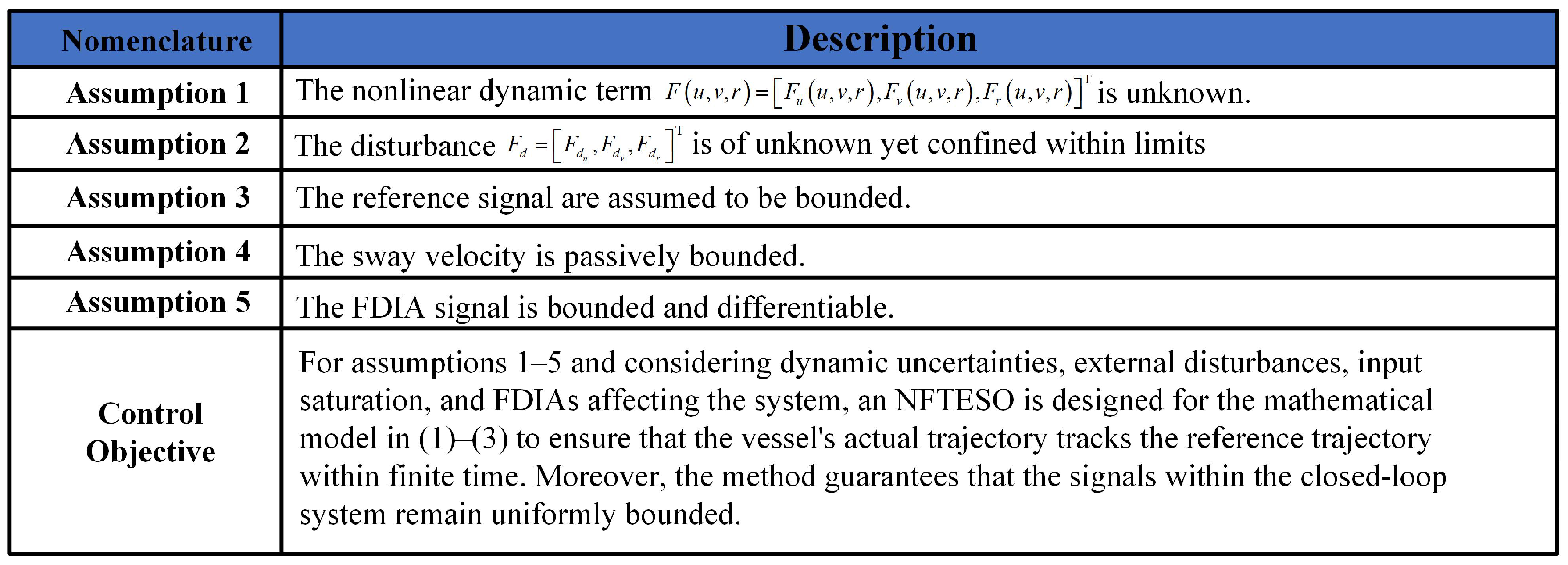
Figure 1. Assumption and control objective.
Jmse 13 01838 g001
Figure 2. Flowchart of the control scheme.
Jmse 13 01838 g002
Figure 3. Reference and actual trajectories in the x , y -plane.
Jmse 13 01838 g003
Figure 4. Reference and actual positions.
Jmse 13 01838 g004
Figure 5. USV’s velocity.
Jmse 13 01838 g005
Figure 6. Tracking errors under FDIAs.
Jmse 13 01838 g006
Figure 7. Control inputs.
Jmse 13 01838 g007
Figure 8. Applied thruster forces.
Jmse 13 01838 g008
Figure 9. Thruster angle ω 1 .
Jmse 13 01838 g009
Figure 10. Thruster angle ω 2 .
Jmse 13 01838 g010
Figure 11. Triggering instants and triggering time.
Jmse 13 01838 g011
Figure 12. Observer estimates of x, y and ψ .
Jmse 13 01838 g012
Figure 13. Observer estimates of u, v and r.
Jmse 13 01838 g013
Figure 14. Observer estimates of Θ u , Θ v and Θ r .
Jmse 13 01838 g014
Table 1. The model variables.
NomenclatureDescription
x , y , ψ T The USV’s position and heading in the inertial coordinate system.
u , v , r T The surge velocity u, sway velocity v, and yaw velocity r.
F d u , F d v , F d r T Unknown environmental disturbances.
F u , F v , F r T Nonlinear dynamic term.
T τ u , T τ v , T τ r T The control input vector constrained by input saturation.
Table 2. Parameters of the control scheme.
ParametersValueParametersValueParametersValue
α 11 30 I 3 α 12 0.1 I 3 α 21 300 I 3
α 22 0.1 I 3 α 31 3000 I 3 α 32 0.1 I 3
σ x a 0.1 σ x b 0.1 σ x c 0.1
λ 11 0.15 λ 12 0.1 λ 21 0.2
λ 22 0.05 λ 31 0.2 λ 32 0.1
λ 41 0.4 λ 42 0.05 ξ p 0.01
ξ ψ 0.01 γ ρ x , y 0.1 θ ρ x , y 0.01
γ ρ ψ 0.01 θ ρ ψ 0.1 λ n , u 100
φ u 1 λ n , r 100 φ r 1
ξ u 0.05 ξ r 0.05 γ ζ u 200
θ ζ u 0.0025 θ ζ u 100 θ ζ u 0.005
γ d u 0.1 θ d u 1 θ d u 0.01
θ d r 1
Table 3. Comparison of the control performance.
IndexesET-NFTESOFT-NFTESOThe Scheme in [1]The Scheme in [11]
x e 1.3821.3911.8251.561
y e 4.9324.9656.0255.481
Number of events363/350319,99919,99919,999
Disclaimer/Publisher’s Note: The statements, opinions and data contained in all publications are solely those of the individual author(s) and contributor(s) and not of MDPI and/or the editor(s). MDPI and/or the editor(s) disclaim responsibility for any injury to people or property resulting from any ideas, methods, instructions or products referred to in the content.