1. Introduction
With the rapid development of the global shipping industry, electric propulsion systems have become the mainstream choice of ship propulsion system due to its environmental friendliness, cost-effectiveness and technical advantages. In this context, the safety and reliability of ship electric propulsion systems have become the core considerations for design and operation. In recent years, permanent magnet synchronous motor (PMSM) has gradually become the core component of ship electric propulsion system due to its high efficiency, high power density and low maintenance cost. However, PMSMs are susceptible to a range of malfunctions over pro-longed periods of operation, including inter-turn short circuits and demagnetization, which can degrade performance and lead to failures in the propulsion system, thereby affecting its operational reliability and navigational safety. Consequently, accurate and timely fault diagnosis of PMSM is crucial to avoid accidents, minimize downtime, and decrease maintenance expenditures, ultimately improving the safety and reliability of ship propulsion systems and promoting the development of intelligent shipping technologies.
Fault diagnosis of PMSM typically involves time-domain and frequency-domain feature analysis, which identifies potential faults by examining variations in the amplitude and frequency of three-phase current signals. Commonly utilized techniques include the short-time Fourier transform [
1], wavelet transform [
2], and variational mode decomposition [
3] are commonly used. While these methods are theoretically advantageous, they encounter practical limitations, particularly under variable speed and load conditions, where signal noise greatly complicates fault detection.
In response to these challenges, researchers have delved into employing image processing methodologies for the smart fault diagnosis of PMSM. They have done this by converting the characteristic signals of the motor’s state into visual image data. This process includes techniques like rotation, scaling, blurring, and shifting, making it possible to visually clarify previously obscured signals [
4]. Pietrzak et al. [
5] suggested a method that leverages stator phase current bispectrum analysis in conjunction with a Convolutional Neural Network (CNN) to assess the health of PMSM stator windings. Similarly, Li et al. [
6] developed a grayscale image algorithm that improves the feature representation of stator currents through an autocorrelation matrix, using a deep CNN for diagnosing eccentricity and demagnetization faults. Additionally, Ping et al. [
7] introduced a customized phase space reconstruction method that improves diagnostic accuracy by transforming leakage magnetic signals into customized phase space reconstruction images for deep feature extraction and encoding. These methods significantly improve feature extraction capabilities over traditional techniques, though the complexity of converting signals to images may limit practical application.
To further enhance diagnostic techniques, researchers have introduced the symmetric dot pattern technique, which projects one-dimensional time-series signals onto a polar coordinate plane [
8,
9,
10]. This method enables intuitive comparisons of signal amplitude and frequency within specific regions, offering an effective and efficient visualization technique with low time complexity. Currently, its primary application is in analyzing vibration signals, with its use on current signals being comparatively limited. This is largely attributed to the three-dimensional nature of time-series information and strong periodicity in current signals, which introduces significant redundancy. To overcome this limitation, Xia et al. [
11] introduced the phase-contrastive current dot pattern (PCCDP), a specialized visualization technique that enhances the representation and processing efficiency of three-phase current signals.
Moreover, comprehensive diagnostic analyses require optimal feature extraction from signal images, for which deep learning, especially CNN, has shown significant potential. CNN are favored due to their sparse connections, weight sharing, and local feature recognition capabilities, making them highly effective for feature extraction. Skowron et al. [
12] have indeed utilized CNN to extract features from the raw stator current data of PMSM for fault diagnosis. Similarly, Wang et al. [
13] applied a one-dimensional CNN to diagnose faults in PMSM by analyzing torque and current signals. However, in complex real-world scenarios, these CNN-based diagnostic models often fail to meet expected results due to challenges in network structure and performance. Addressing these limitations, He et al. [
14] introduced the Residual Network (ResNet), which utilizes residual connections to ease parameter optimization and enhance network depth, thereby improving feature extraction capabilities. Additionally, Ma et al. [
3] combined the robust fault feature extraction capabilities of ResNet with bidirectional long short-term memory networks to accurately classify faults in propulsion motor drive inverters. Mahmoud et al. [
15] utilized ResNet-18 to enhance the network’s learning capabilities during training, effectively diagnosing various faults in PMSM. Despite these developments, the traditional residual unit modules have exhibited certain limitations. Progressing further, He et al. [
16] observed that the original residual unit’s structure impeded the model’s learning capacity during training, leading to the development of the pre-activated residual unit, which consistently outperforms the original.
Inspired by the existing literature, this paper introduces an innovative method for fault diagnosis in PMSM by leveraging an improved residual network (IResNet) coupled with PCCDP images. Initially, the Hunter-Prey Optimization (HPO) algorithm optimizes the PCCDP parameters to accentuate fault distinctions. Following this optimization, the current signals are converted into detailed PCCDP images, enhancing the visualization of various PMSM states. The methodology further integrates a pre-activated Residual module equipped with an attention mechanism that prioritizes significant channels based on data features. This adaptation enables the model to concentrate on critical feature channels, which significantly enhances performance across various conditions and ensures accurate fault diagnosis in PMSM.
A primary strength of this study lies in the proposed method, which not only visually displays changes in PMSM current fault signals but also automatically extracts fault characteristics, which significantly enhances the effectiveness of fault diagnosis. The key contributions encapsulated in this paper are outlined below:
- (1)
Utilizing PCCDP technology, this method transforms current signals into images that depict the state of the signals. Furthermore, it employs a combined measure of Euclidean distance and cosine similarity to optimize PCCDP parameters.
- (2)
By integrating PCCDP with an IResNet, the method automates the extraction of deep features from the current signal states, streamlining the diagnostic process.
- (3)
Integrating the squeeze-and-excitation (SE) module into the ResNet architecture enhances the model’s capacity to learn the relationships between channels, which in turn improves its feature recognition capabilities. This integration significantly amplifies both the accuracy and robustness of the fault diagnosis process.
The structure of this paper is outlined as follows:
Section 2 delves into the mathematical description of the PMSM drive system.
Section 3 provides a detailed description of the proposed fault diagnosis framework for PMSM.
Section 4 provides a comprehensive description of the experimental process undertaken and offers a thorough analysis of the obtained results. Finally,
Section 5 concludes the work and outlines future research directions.
3. Proposed PMSM Fault Diagnosis Framework
The framework for the proposed PMSM fault diagnosis method based on IResNet, is first introduced in this section and then provides a detailed explanation of this fault diagnosis method.
3.1. Overview of the Proposed Framework
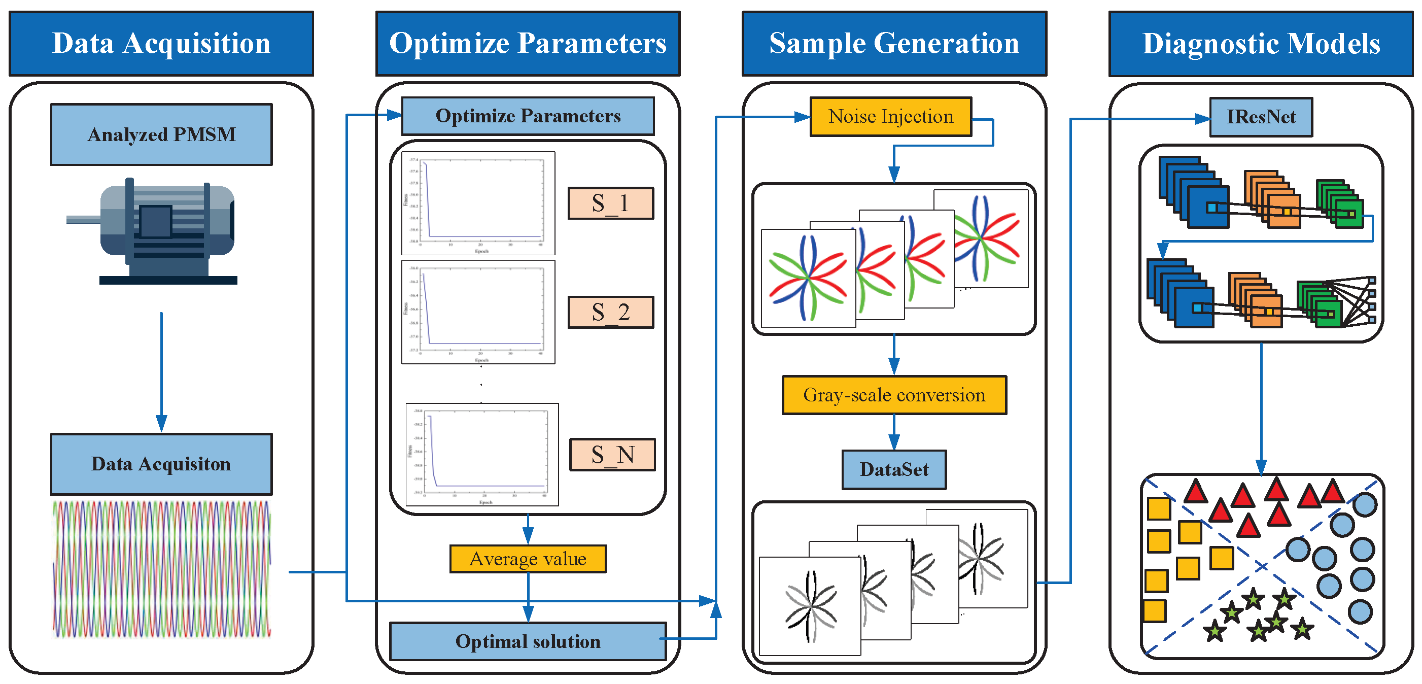
Figure 3 depicts the structure of the proposed method detailed in this paper, which is primarily composed of four key sections: Data acquisition, parameter optimization, sample generation, and fault diagnosis. Firstly, the current signals of PMSM in different fault states are collected by the simulation model; secondly, the key parameters in the transformation process are optimized using the HPO algorithm in order to generate PCCDP images with high variability; then these image samples are input into a well-trained fault diagnosis model; finally, the model learns the image features to realize the accurate identification of PMSM faults. The detailed diagnosis steps are shown below:
- (1)
Data Acquisition. The data were acquired via model simulation. Firstly, the corresponding fault simulation model is constructed in Simulink according to the PMSM fault mathematical model. Secondly, the PMSM parameters are input to simulate the PMSM operation state under various faults and different operating conditions. Finally, stable current signals are extracted from the simulation results for acquisition.
- (2)
Image discrepancy optimization. To further improve diagnostic effectiveness, we need to make the correlation between the images corresponding to each fault state as small as possible before image transformation. Therefore, we need to optimize the PCCDP image parameters. First, the acquired three-phase current signals are divided into a sequence of samples with a fixed size. Subsequently, the HPO algorithm is used to optimize the parameters of the images, and the image discrimination function is used as the metric for evaluating the algorithm’s performance to ultimately obtain the optimal parameters of the images.
- (3)
Sample generation. To ensure the data acquired from the simulation realistically reflects the actual performance of PMSM, Gaussian white noise is injected into the segmented current samples to simulate noise in real applications [
11]. Then, based on the optimized parameters, the noise-injected samples are converted into corresponding PCCDP grayscale images.
- (4)
Based on IResNet diagnostic models. Enhancing the network’s feature extraction capacity involves improving the conventional ResNet by incorporating the SE attention mechanism into the pre-activated residual units, which bolsters the model’s fault feature extraction efficacy. Subsequently, this enhanced model is implemented in the fault diagnostic procedure for PMSM, facilitating the accurate identification of motor malfunctions.
3.2. Data Acquisition
First, the mathematical model was established based on the operational characteristics of PMSM under different fault states. Subsequently, the PMSM control system model based on Field-Oriented Control algorithm was constructed on the Simulink simulation platform, with the control system as shown in
Figure 4. Finally, motor-related parameters were input into the model for simulation, thereby obtaining the three-phase current signals of the motor, with the simulation parameters related to the motor shown in
Table 1.
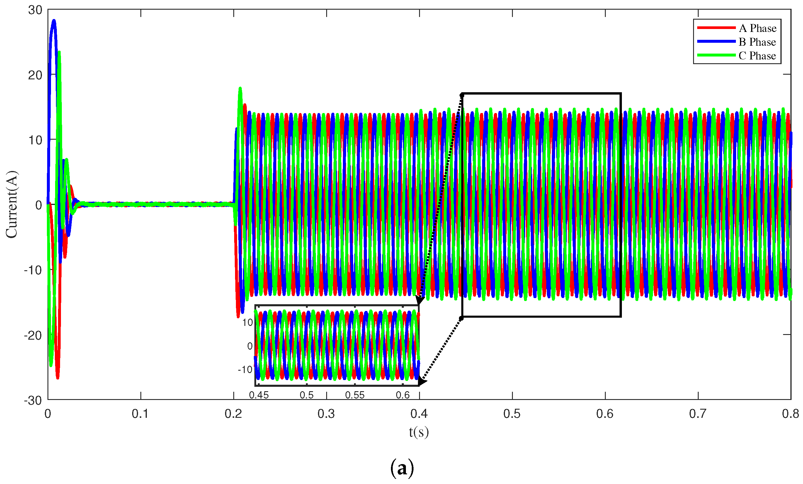
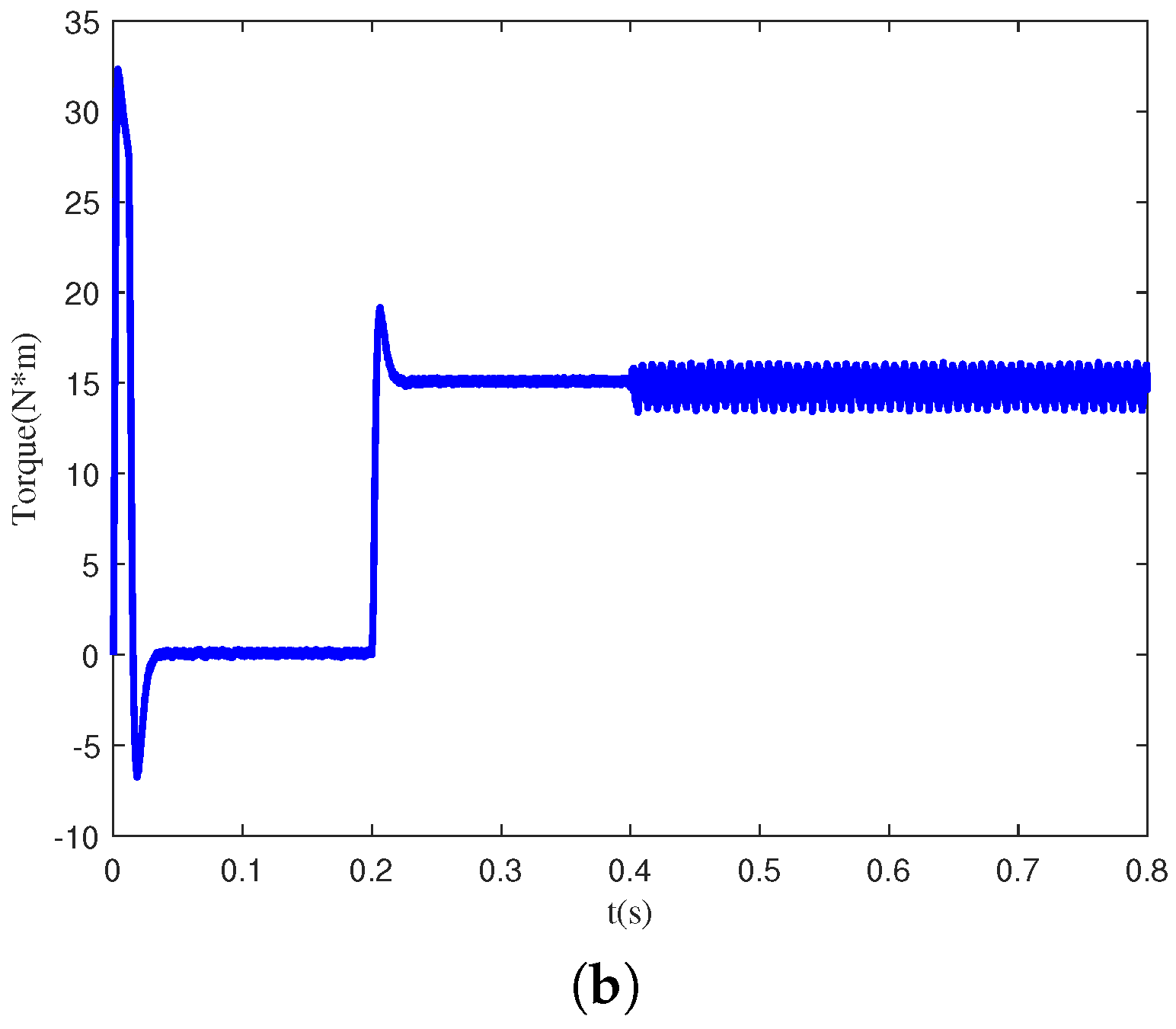
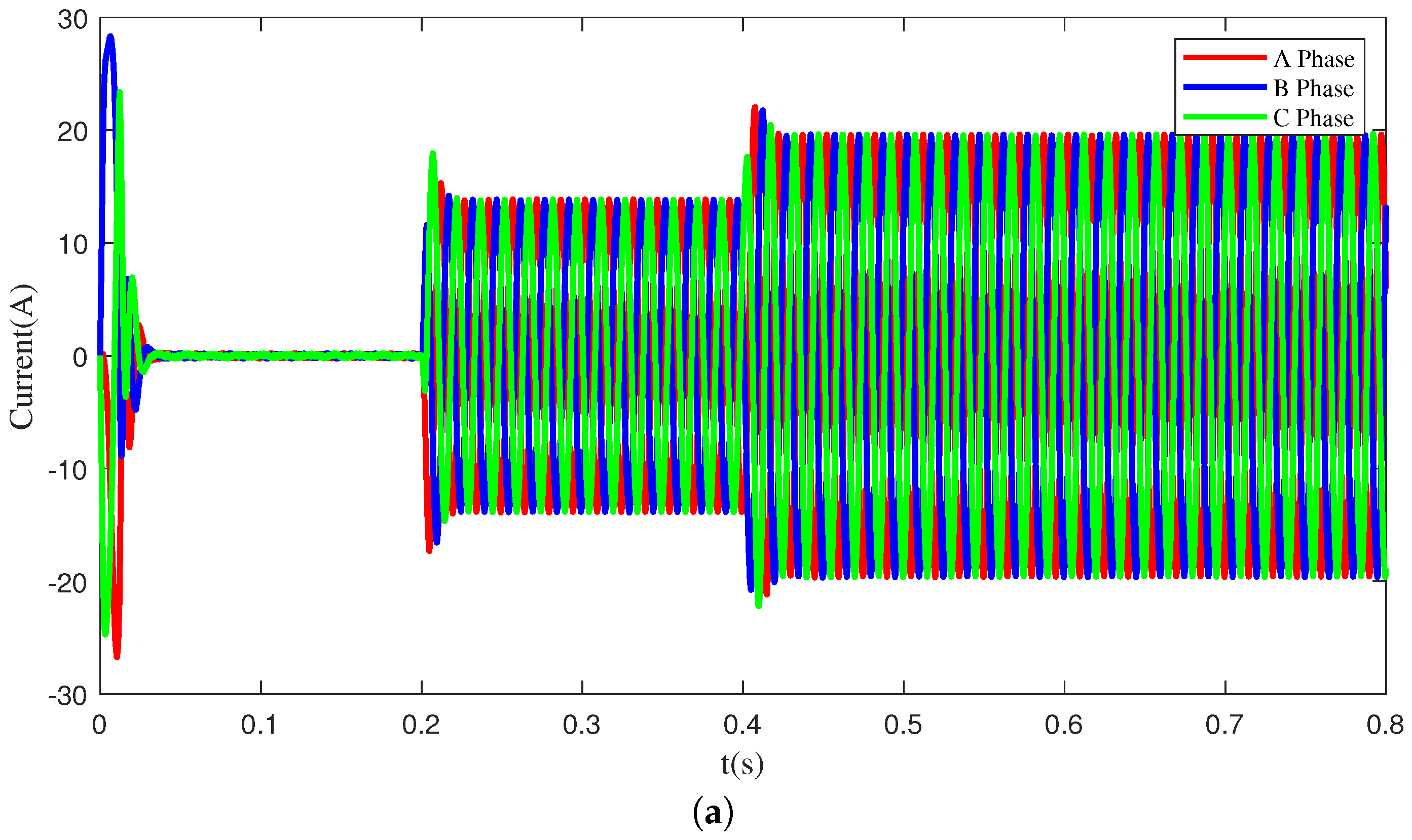
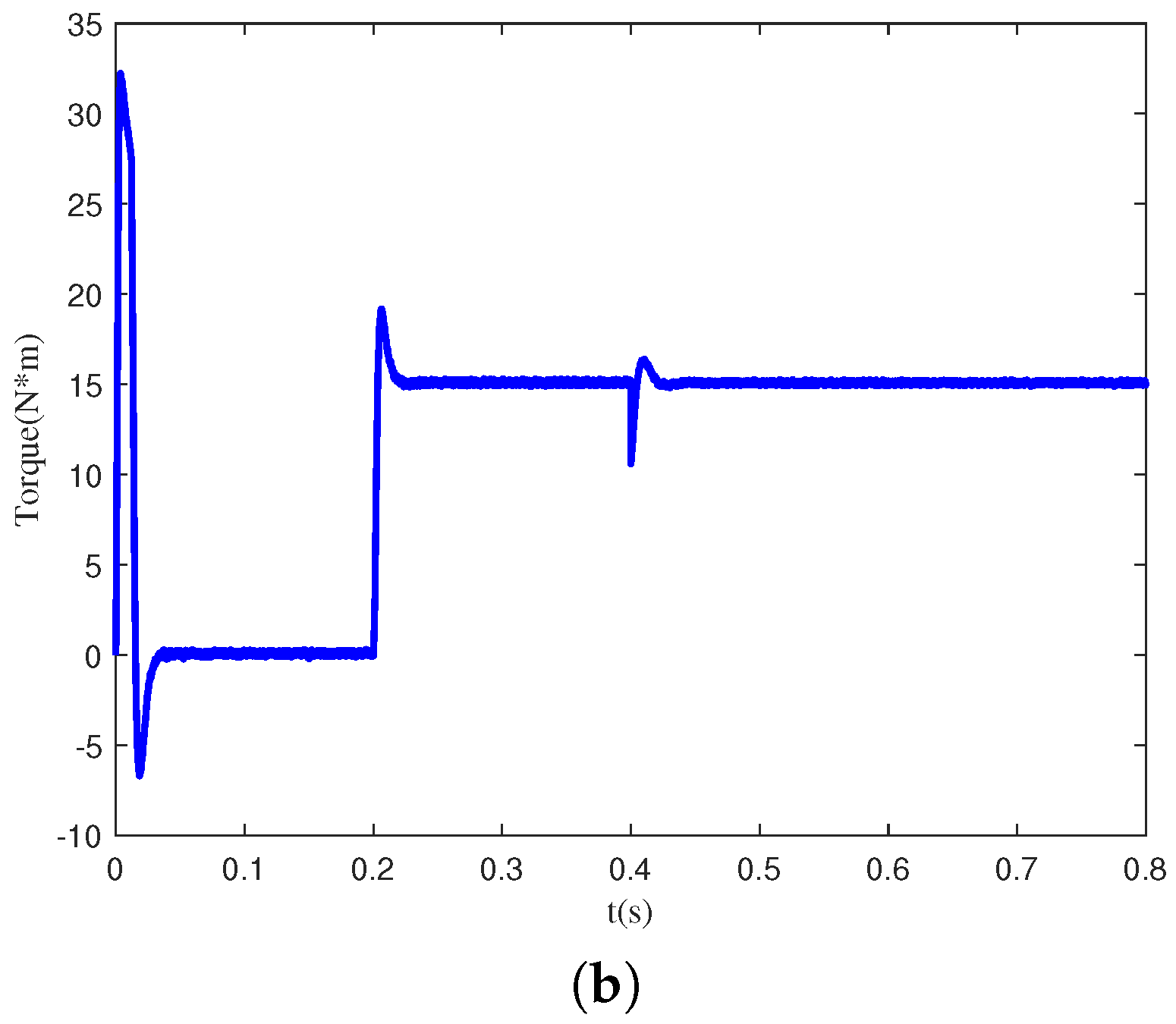
To ensure comprehensive data collection, the PMSM operating conditions are categorized prior to fault simulations. Consequently, torque and speed serve as the parameters for defining these conditions. Specifically, two speed levels, 750 rpm and 1000 rpm, and four torque levels, 25%, 50%, 75%, and 100% of the rated torque, are selected. This categorization results in eight distinct operating conditions. To enrich the data obtained from the fault simulation model, fault parameters are also categorized. In the inter-turn short circuit fault simulation, fault severity and short circuit resistance are used as parameters for division, with fault severity divided into 5% and 10%, and short circuit resistance divided into 0.01, 0.1, 0.5, and 0.8. Similarly, in the demagnetization fault simulation, amplitude demagnetization and angle demagnetization are used as parameters for division, with amplitude demagnetization divided into 25% and 50% of the magnetic flux linkage, and angle demagnetization divided into 30° and 20°. By categorizing the parameters of the PMSM simulation model according to the above methods, we successfully acquired different current signals of PMSMs under various health states and operating conditions, providing rich data support for subsequent fault diagnosis.
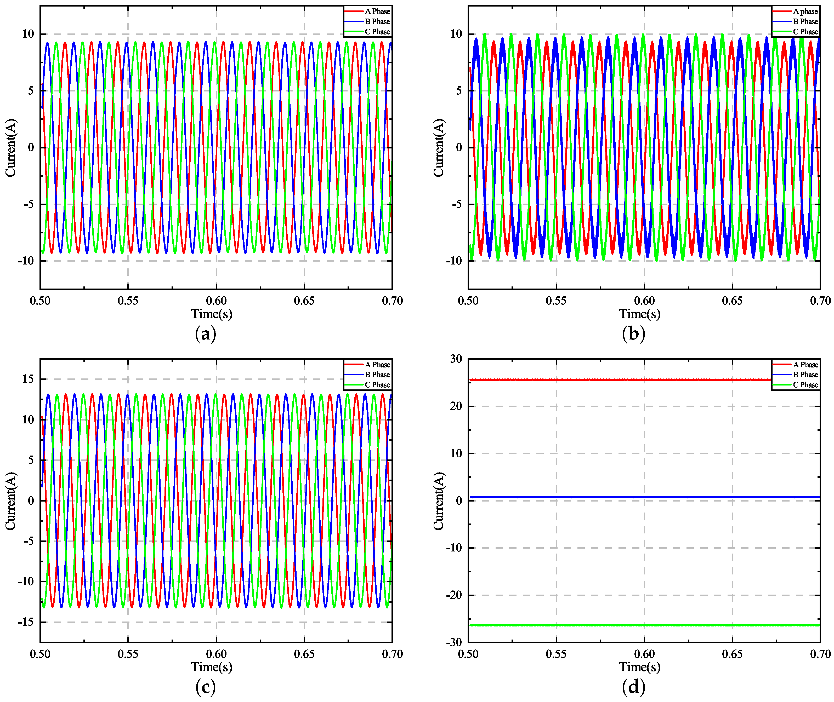
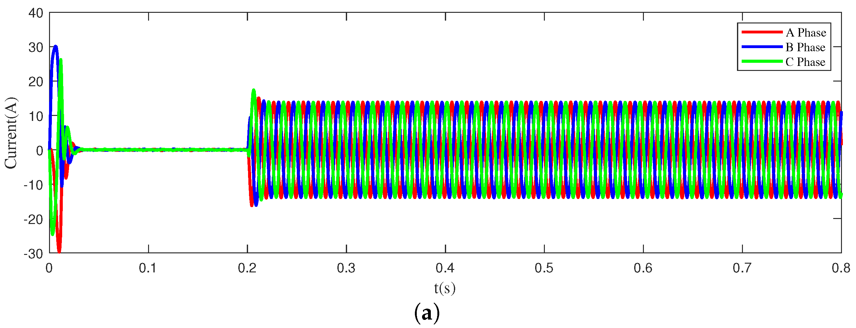
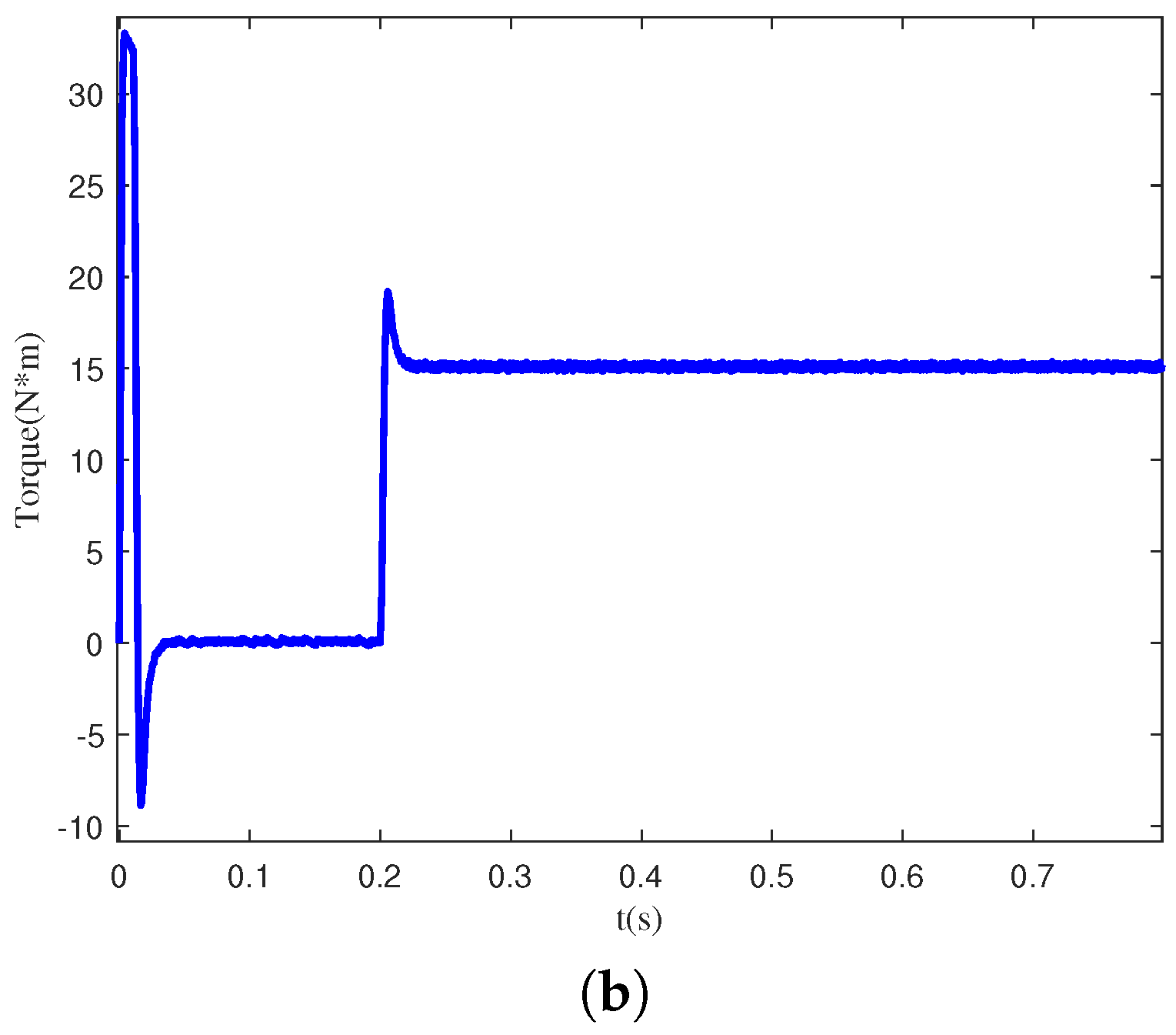
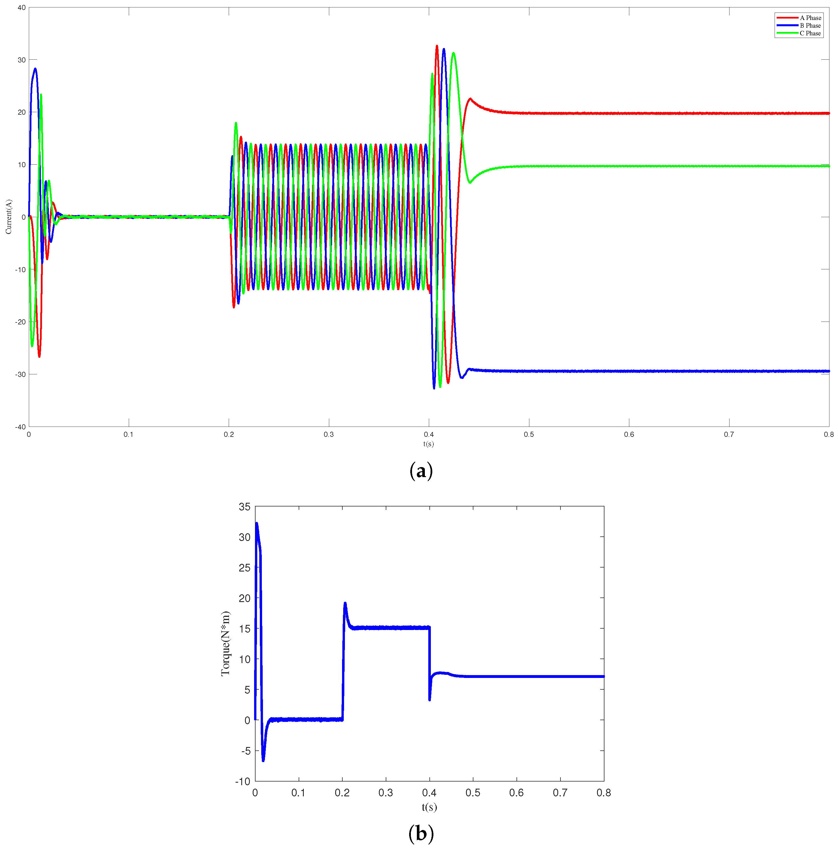
Figure 5 shows the current signals of PMSM in four different states: normal, inter-turn short circuit, light demagnetization, and heavy demagnetization. From
Figure 5, it is evident that the current signals in the normal state are sinusoidal waves with balanced three-phase output. However, the inter-turn short circuit fault signal exhibits a significant imbalance among the three phases, and the amplitude of this signal varies over time. Additionally, the difference between the light demagnetization fault signal and the normal state signal of the motor is not readily apparent to the naked eye, involving only changes in amplitude. For the heavy demagnetization fault signal, due to heavy demagnetization faults in the motor affecting normal operation, the current waveform no longer changes.
3.3. Image Discrepancy Optimization
This paper employs the HPO algorithm to refine the parameters of PCCDP images, utilizing the image degree of difference function as the evaluation criterion for the optimization process. This section explains the fundamental principles of PCCDP images, the HPO algorithm, and the image degree of difference function.
3.3.1. PCCDP
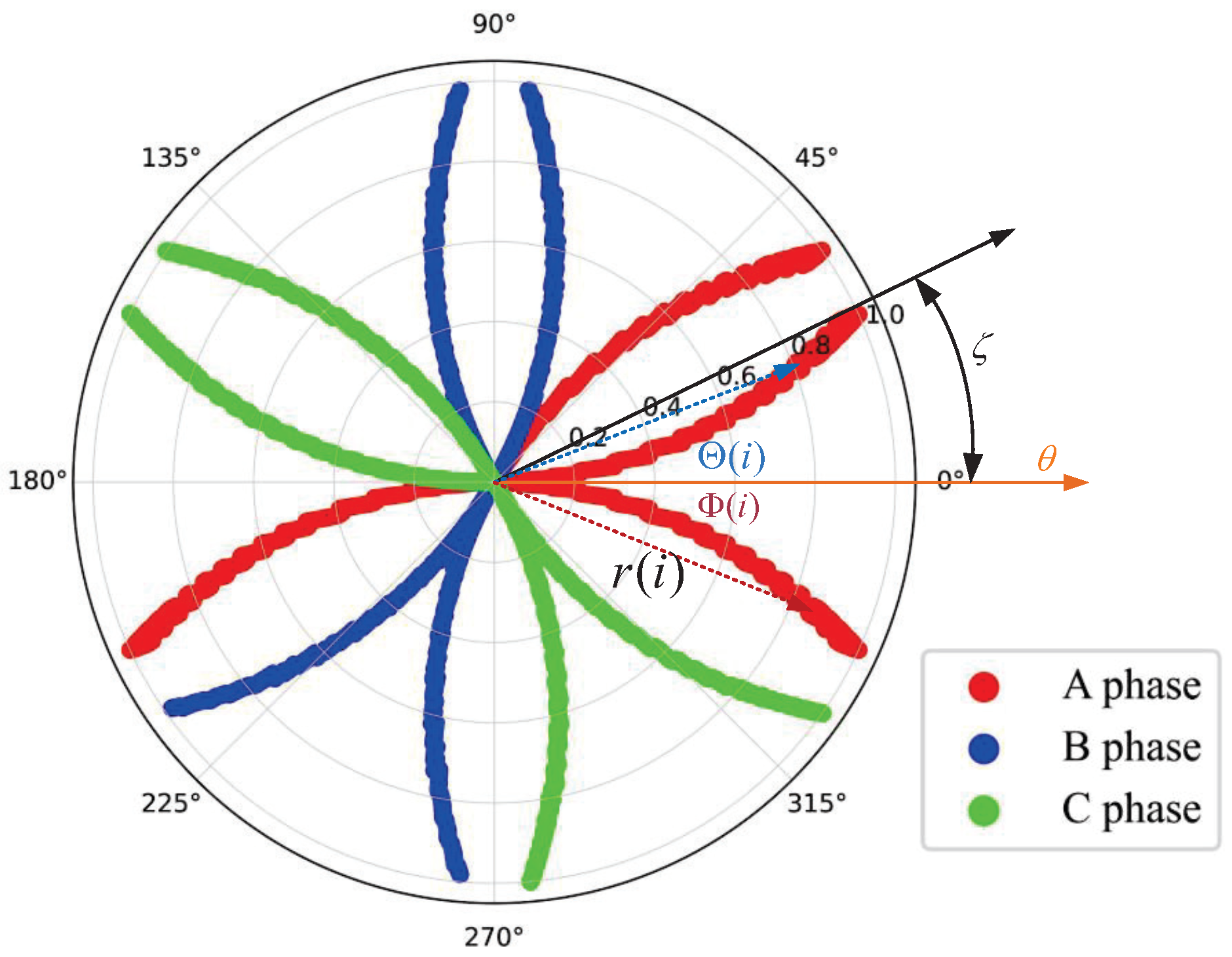
The PCCDP image method is a visualization technique for three-phase current signals, with its implementation process shown in
Figure 6. It divides the entire polar coordinate plane into six 60° sectors, mapping two-phase current signals in each sector [
11]. Three-phase current information is mapped onto two convex and two concave lobes. Each phase’s current data point corresponds to each point on the lobes. Thus, in the polar coordinate system, each point maps to four points with the same radius but different angles. For each sampling point in each phase of the current, its radius is expressed as:
where
denotes the
ith sampling point of each phase current signal,
and
denote the minimum and maximum values of the current, respectively.
The angles of the convex and concave lobes have been calculated as variables. The angle of the convex pleated lobe is expressed as:
where
denotes the angular amplification factor and
denotes the predefined time interval factor.
The angle of the concave pleated leaf is denoted as:
The visualization of three-phase current signals can be achieved by using the above method, which can intuitively reflect the frequency and amplitude changes of the signals.
When creating PCCDP images, to minimize the overlap of the three-phase current signals, appropriate upper and lower bound parameters can be set.
is used as the angular amplification coefficient, and the upper boundaries should not exceed 30°. Beyond this range, part of the signal will overlap, considering the drawing process will produce errors, the range can be set at [5, 28],
is generally set to [1, 10] [
8].
3.3.2. HPO
Drawing inspiration from the interactions between predators and their prey, the HPO algorithm is used to optimize two parameters [
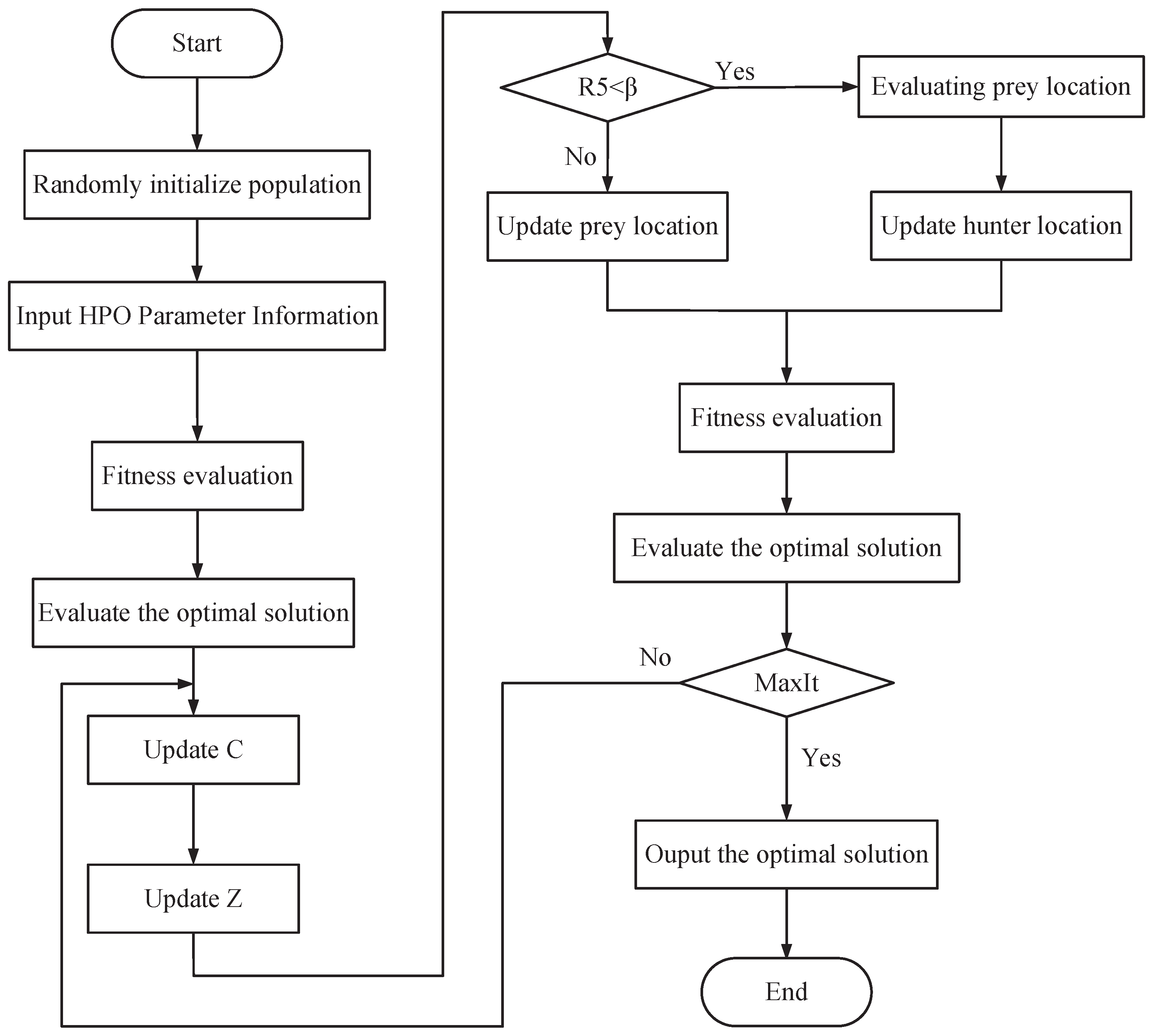
22]. In this algorithm, the prey represents solutions within the problem space, while the predators act as search agents. To ensure its safety, the prey continually seeks the global optimum to evade predators. Predators target prey that strays from the group and strive to find the optimal solution through continuous iterations and strategy updates, as shown in
Figure 7. The specific optimization process of the HPO algorithm involves the following three parts:
- (1)
Initialization of population positions. The random positions of the initialized populations are distributed as shown below:
where
denotes the initial position of the hunter or prey,
d denotes the dimension,
denotes the upper limit of the solution space vector, and
denotes the lower limit of the solution space.
- (2)
Hunter position update. Utilizing the distance to the prey’s position from the mean position, the hunter can dynamically modify their own location. The mechanism for the hunter’s search strategy is detailed as follows:
where
is the current position of the hunter,
is the position of the hunter in the next iteration, and
is the position of the prey;
is the average of the positions of all populations; and
Z is the fitness parameter computed from Equation (
35):
where
and
are random vectors between
and
is a random value of
.
is the index at which
satisfies condition
.
C is the balance parameter between exploration and exploitation, and its value decreases from 1 to 0.02 during the iteration process. The formula is as follows:
where
is the current iteration value and
denotes the maximum number of iterations. The prey’s position is determined based on the individual’s distance from the mean position within the population, with the individual farthest from the mean being designated as the prey. Firstly, the mean value of each all positions should be calculated as:
Next, the distance from the prey to that average position is calculated as:
Finally, the one with the largest distance is captured as the prey with the formula:
When a hunter captures a prey, the prey dies and next time, the hunter moves to a new prey. To address the issue, we implement a diminishing mechanism, namely:
where
N is the number of hunters. Substituting Equation (
40) into Equation (
39) yields the recalculated hunter position as:
- (3)
Prey position update. When the prey is discovered by the hunter and started to be caught, the prey will move to the safe position, which is called the global optimal position. its position update formula is as follows:
where
,
j, and
denote the current and next prey positions, respectively,
is the currently obtained best position, and
is a random value in between
.
3.3.3. Image Degree of Difference Function
In this study, we utilize a fusion of Euclidean distance and cosine similarity as the degree of difference function, which fully considers the distance and angle differences between the data. The detailed process is as follows:
First, assume that the pixel matrix of a grayscale image can be represented as:
where
m denotes the number of rows and
n denotes the number of columns of the pixel matrix. For a certain fault state information, it can be represented by the average value
of the pixel matrix of all sample information contained in that state.
Secondly, a fusion of Euclidean distance [
23] and cosine similarity [
24] is used as the degree of difference function. The representation difference between state
k and state
u can be defined based on the cosine similarity as:
where
is the cosine similarity between the data, with smaller values indicating less similarity.
The difference in representation between state
k and state
u can be defined based on the Euclidean distance as:
where
is the Euclidean distance between the data, with larger values indicating less similarity.
From the above analysis and fully considering the distance and angle differences between the data. From this, the degree of difference function between state
k and state
u is obtained as:
where
is the moderating factor, the smaller
is, the smaller the similarity is. Then the degree of difference function of the
N-class PCCDP image is:
3.4. Based on IResNet Diagnostic Models
In this section, we introduce an IResNet as a model for fault diagnosis in PMSM. This model enhances the pre-activated residual module and integrates the SE channel attention module, thereby improving the performance and generalization capabilities of the diagnostic model.
3.4.1. Basic Components
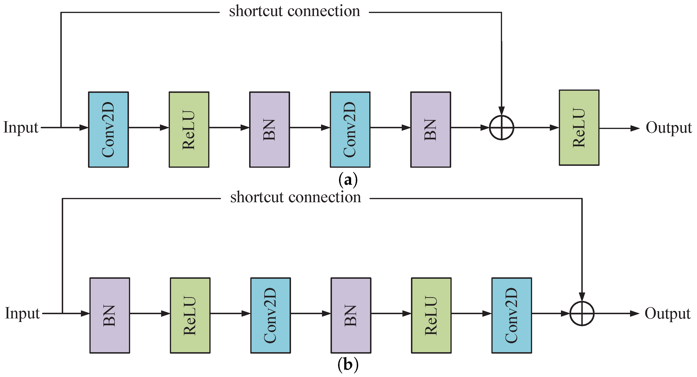
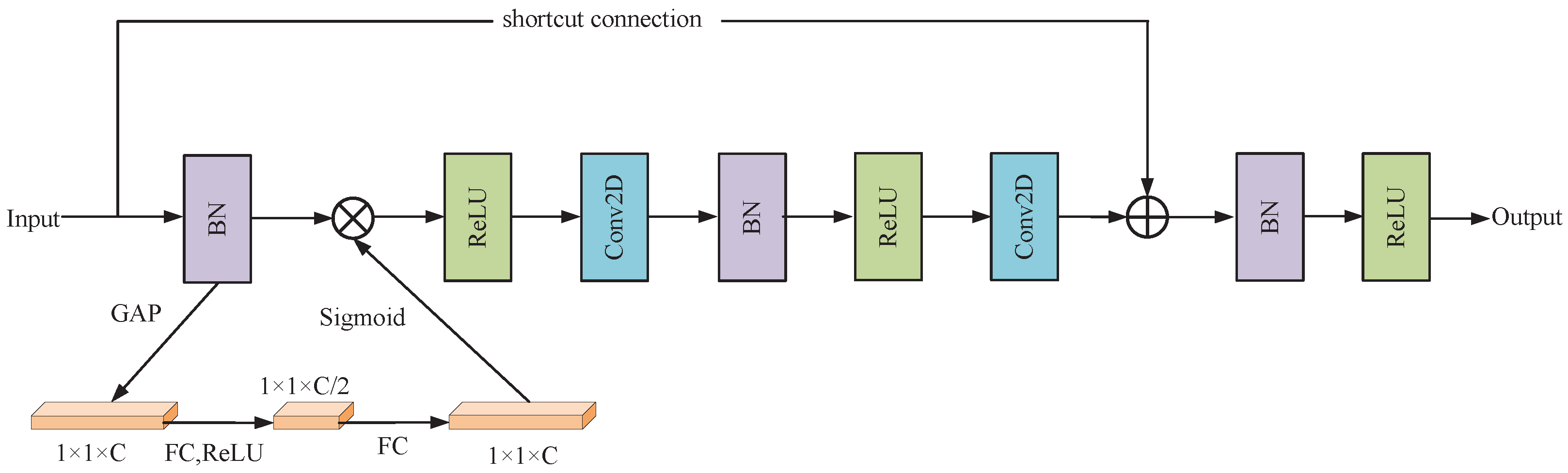
The fault diagnosis model will use the pre-activated residual unit as the basic building block, and the common residual module structure is shown in
Figure 8.
Figure 8a represents the original residual module and
Figure 8b represents the pre-activated residual module. As depicted in the figure, each residual module comprises two Batch Normalization (BN) layers, two Rectified Linear Unit (ReLU) activation functions, two convolutional layers, and a shortcut connection. In the original network structure of the basic residual block, the signals are not normalized before entering the branches, and the distribution of each layer gradually shifts or changes as the network is superimposed, which causes difficulties in network learning. However, the pre-activated ResNet highlights more advantages, structurally simplifying the ResNet structure compared to the original basic residual block. Moreover, the pre-activation unit improves the model is regularization, which makes the model easy to optimize by stabilizing the distribution of input values.
3.4.2. SE Networks
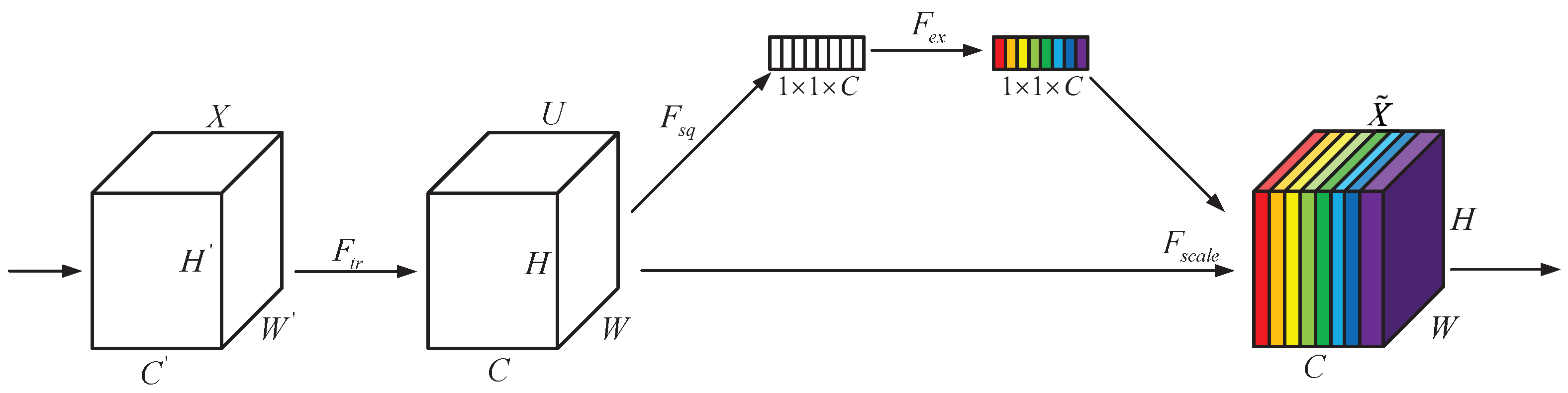
Singular residual connections fail to learn channel importance, diminishing attention to crucial features and degrading feature extraction performance. The SE channel attention mechanism adaptively learns the significance of each channel, enabling the network to concentrate more on pivotal features. The core idea is to compress and excite input features; specifically, it includes two primary steps: squeezing and excitation, as illustrated in
Figure 9. In the process of feature compression, the input feature map undergoes reduction through global average pooling to form a vector, which is subsequently downsized into a more compact vector by a dense layer. In the subsequent excitation phase, a sigmoid function is applied to scale each component of the vector between 0 and 1. The scaling vector is utilized to weight and modulate the original input feature map, thereby creating a feature map that emphasizes the most significant features.
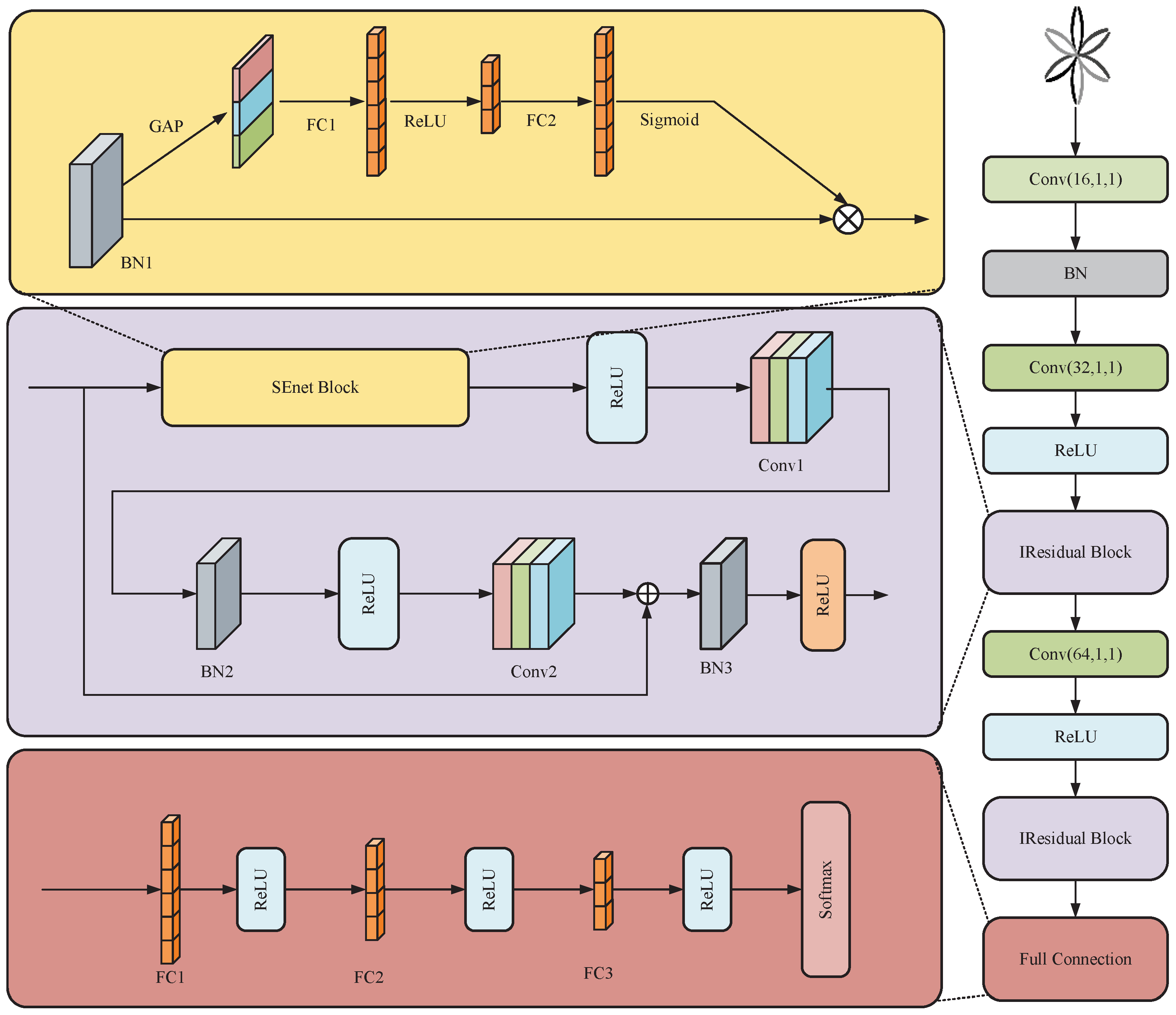
3.4.3. IResNet Architecture Design
The architectural design of the ResNet model developed in this research is depicted in
Figure 10. This model structure has two main differences compared with the original pre-activated residual block: first, the original pre-activated block information propagation is also not applied regularization on the path of the most direct unit constant mapping, which is prone to over-fitting phenomenon. In this regard, a BN layer needs to be added after the addition operation to regularize the signal output. Then activation is performed through the ReLU layer to avoid over-fitting phenomenon and improve the feature learning ability of the model. Secondly, to enhance the ability of the network to recognize important fault features, the SE module is integrated into the residual unit, and this integration suppresses less relevant fault features, thus improving the sensitivity and robustness of fault diagnosis.
In the
Figure 10, Conv is mainly responsible for the convolution operation [
25], equation:
where * denotes the convolution operation,
k denotes the index of the layer,
i denotes the index of the convolution kernel, and
and
denote the bias and weight of the first layer, respectively.
denotes batch normalization, which makes the input values become standard normal distribution [
26]. It can effectively avoid the disappearance of low-level gradients during back-propagation and prevent over-fitting. The calculation process is as follows:
where
m denotes the training batch size,
denotes the input sample,
denotes the sample mean,
denotes the sample standard deviation, and
denotes the normalized sample.
denotes very small constant,
and
denote learnable parameters.
ReLU is a prevalent nonlinear activation function that efficiently mitigates the issue of vanishing gradients, making it a staple in deep learning applications. The ReLU activation function is mathematically defined as:
GAP is a common pooling operation that computes the average of each feature map, providing a holistic representation of that feature. Utilizing the GAP technique can streamline the model’s architecture, decrease the parameter count, enhance the network’s generalization capabilities, and to a certain extent, curb the over-fitting phenomenon.
Within the SE channel attention mechanism, the input tensor undergoes global average pooling to condense the spatial dimensions of the feature map into a 1 × 1 × C tensor, with C representing the channel count. Subsequently, the channel dimension is reduced to C/2 by a dense layer. This intermediate representation is then subjected to a ReLU activation function to introduce nonlinearity. Following this, the channel dimension is expanded back to C channels via another dense layer. Ultimately, a sigmoid activation function is applied to produce attention weights ranging between 0 and 1. These weights are used to scale the elements of the original input tensor, yielding a feature representation that reflects the learned importance of each feature.
The overall structure is shown in
Figure 11. The input to the network is a grayscale PCCDP image with dimensions of 64 × 64 × 1 pixels. The core structure of the network is composed of a preprocessing layer, an SE module, and a cascade of residual blocks that are stacked together.
5. Conclusions and Future Works
In this study, a novel method for motor fault diagnosis is introduced. Initially, the fundamental principles behind inter-turn short circuit and demagnetization faults in PMSM are examined, and stator current data are gathered through a Simulink simulation. Subsequently, the HPO algorithm is deployed to optimize the PCCDP parameters, aiming to enhance the distinguish ability of different fault states. Ultimately, an advanced diagnostic model based on a residual network is proposed, enhancing the diagnostic accuracy and enabling the identification of four distinct fault states in PMSM. The experimental outcomes demonstrate that this method not only offers superior diagnostic performance across various PMSM fault states but also boasts rapid convergence and effective fault detection capabilities. The conclusions drawn from this paper are as follows:
- (1)
The HPO algorithm is used to determine the optimal parameters within the PCCDP technique. The maximization of the combined metrics of Euclidean distance and cosine similarity serves as the objective function, aiming to enhance the differentiation between varying degrees of faults.
- (2)
The pre-activated ResNet module has been enhanced by incorporating the SE attention mechanism, which significantly boosts the model’s capacity to extract fault-related features.
- (3)
For practical engineering applications, this paper introduces an innovative fault diagnosis method, steering towards more intelligent fault diagnostics.
The fault diagnosis method proposed in this paper only investigates two types of faults, inter-turn short circuit and demagnetization, in the PMSM stator winding, which can provide high diagnostic accuracy but still has some limitations, mainly in the fact that there are fewer types of faults, and further adjustment and optimization may be required to adapt to different types of faults or under different conditions. This may affect its generalizability to different propulsion systems. Secondly, the long experimental period for the whole diagnosis of our method may require a relatively long time for data processing and model training. In the future, we will conduct more extensive experimental studies on other fault types of PMSM to expand the dataset, and at the same time, we need to consider how to simplify the model in order to reduce the computational complexity while maintaining sufficient accuracy, and finally apply the fault diagnosis method in reality.


