Article

Research on the Ignition Strategy of Diesel Direct Injection Combined with Jet Flame on the Combustion Character of Natural Gas in a Dual-Fuel Marine Engine

College of Power and Energy Engineering, Harbin Engineering University, Harbin 150001, China
*
Author to whom correspondence should be addressed.
J. Mar. Sci. Eng. 2024, 12(6), 857; https://doi.org/10.3390/jmse12060857
Submission received: 19 April 2024 / Revised: 16 May 2024 / Accepted: 19 May 2024 / Published: 22 May 2024

Abstract

:
In large-bore two-stroke diesel/nature gas dual-fuel marine engines, a certain quantity of diesel is injected into the cylinder to satisfy the full-power output engine rated power of the gas mixture. However, the ignition and flame propagation process based on the injection strategy of diesel direct injection combined with diesel jet flame on the ignition and combustion of natural gas is unclear, which directly affects the power and the thermal efficiency of engine and emissions. Therefore, this work numerically investigates the flame propagation characteristic under the strategy of the main and pilot diesel modes. The influence of the injection timing and proportion of diesel on combustion and emission performance are further analyzed. The results show that the influence of the injection timing of main diesel (MDIT) on the combustion process and emission performance is more obvious than that of the injection timing of pilot diesel (PDIT). The results indicate that the MDIT increased from −2°CA to −8°CA, the power increased by 316 kW, and the thermal efficiency improved by 1.5%. However, the CO2 emissions increased by 10.5 g/kWh, and the NOx emissions increased by 0.7 g/kWh. Additionally, an early PDIT is not conducive to the rapid organization of combustion, resulting in decreased engine power and thermal efficiency. Furthermore, it was found that the power improved by 50 kW and the thermal efficiency improved by 0.6%, with a decrease in the main diesel ratio (MDR) from 100% to 90%. Meanwhile, the CO2 emissions decreased by 4 g/kWh, although there was no obvious change in NOx emissions with the advance of MDR.

1. Introduction

Recently, greenhouse gas emissions from marine engines have increased, owing to the development of the ocean transportation industry [1]. According to the Fourth International Maritime Organization (IMO) GHG Study 2020, greenhouse gas emissions from the global shipping industry reached 1.07 billion in 2018 [2]. Therefore, governments and organizations have imposed strict environmental protection requirements [3]. The IMO sets out a plan to reduce greenhouse gas emissions from ships. The total greenhouse gas emissions should be decreased by over 40% from 2008 levels by 2030 and by 70% by 2050 [4]. The IMO focuses on measures that can be taken to meet the 2030 shipping emissions reduction targets. An effective strategy to meet emission regulations and control global warming is to reduce CO2 emissions by seeking low-carbon fuels to replace fossil fuels in marine engines [5]. Natural gas (NG) is widely recognized as having great potential to reduce CO2 emissions [6]. Theoretically, Liquefied Natural Gas (LNG) can decrease CO2 emissions by approximately 25% in comparison to other fuel oils [7]. Therefore, natural gas has been adopted as a fuel in marine engines in recent years, and LNG has been extensively used as a marine fuel in ocean transportation ships [8].
Currently, compared with high-pressure gas injection, low-pressure natural gas/air dual-fuel marine engines have become the preferred choice for large-bore marine transportation owing to their lower NOx emissions and equipment costs [9,10]. To extend ignition energy and ensure combustion stability, diesel jet ignition is widely recognized as an ignition technology for large-bore dual-fuel marine engines. Therefore, to obtain the influence law of diesel combustion on the flame propagation and development in a cylinder, researchers conducted relevant experimental and simulation studies on the effects of pilot fuels on ignition and combustion [11,12,13]. Simpson [14] and Shin [15] investigated the influence of pre-combustion chamber structural parameters and nozzle design on the development of flame. They found that the nozzle parameters have a direct impact on the combustion stability and NOx emissions. In 2020 and 2022, Ju et al. [16] found that adjusting the aperture size of a pre-combustion chamber jet could improve the uniformity of flame development in the cylinder and increase the heat release rate. The same conclusion was obtained in a study by Wei et al. [17], they reported that the mass flow rate is obviously affected by the decrease in the injector nozzle hole size, which affects the spray atomization and combustion process.
Other studies have been conducted to research the impact of the pilot fuel on flame propagation and engine power. By studying the influence of pilot diesel parameters on flame propagation, Li et al. [18] concluded that combustion stability is improved by decreasing the injection interval and pressure. Meanwhile, they found that the fuel economy is improved when the injection timing is properly advanced. Yousefi et al. [19] and Cong et al. [20] studied pre-main-post diesel injection and proposed a reasonable strategy for dual-fuel combustion through experiments and simulations. They found that this strategy could significantly reduce greenhouse gas and NOx emissions by 10% and 47%, compared to the original fuel injection strategy. Liu et al. [21] and Liu et al. [22] analyzed the influence of pilot fuel consumption on the flame propagation and pressure oscillation in the cylinder of a dual-fuel marine engine. The results showed that the ratio of pilot diesel was more sensitive to combustion in the cylinder when the equivalence ratio was lower, and that decreasing the quantity of the pilot fuel could effectively reduce the knock intensity. This conclusion was confirmed in a study conducted by Wang et al. [23]. Other studies have concentrated on investigating the effects of the pre-chamber structural parameters on flame development in the main combustion chamber [24,25]. They found that the position of the pre-chamber and the arrangement of holes were the keys to the pre-chamber design, which influenced the flame propagation of the main combustion chamber.
According to the literature reviewed above, it can be deduced that the technology of diesel jet ignition effectively improves the ignition energy, and the timing and quantity of the pilot fuel injection significantly influence spray development and flame propagation in the pre-chamber. At the same time, it can be found from previous studies that optimizing injection timing and injector parameters can effectively reduce pollutant emissions from marine engines. Hence, it can be concluded that the pilot fuel injection strategy and injector parameters have a direct impact on the engine performance of dual-fuel marine engines. However, knocking occurs in the cylinder under high load conditions for some large-bore marine dual-fuel engines when only diesel as the pilot fuel is injected to ignite the natural gas in the main combustion chamber. Therefore, the strategy of a certain quantity of diesel injected into the main combustion chamber was adopted to achieve full power output. However, previous studies have focused on small and medium-sized engines or diesel only, as the pilot fuel is injected to ignite the natural gas in the main combustion chamber for the low-speed marine engine. The flame propagation and combustion processes under a strategy of main and pilot diesel have an obvious difference compared to those of previous studies, and the influence of the diesel injection strategy in the large-bore marine dual-fuel engine on combustion and emission performance is not certain.
Therefore, the main content of this study is to further research the influence of the injection strategy of diesel direct injection combined with diesel jet flame on the ignition and combustion of natural gas in a large-bore, two-stroke marine engine. Meanwhile, the appropriate injection parameters of this strategy on engine power and thermal efficiency in dual-fuel marine engines are proposed for improving engine combustion performance and reducing emissions, which provides theoretical support for the selection of ignition strategy and diesel injection parameters and will expand the application of natural gas in marine engines. First, a 3D computational fluid dynamics model was set up for calculating the combustion process in a low-speed dual-fuel marine engine. Subsequently, the flame propagation characteristics of diesel direct injection combined with diesel jet flame in the cylinder were analyzed by different injection timings and quantities of main and pilot diesel. Finally, the influence of different timing and ratios of diesel injection on diesel jet flame propagation, combustion process, emission, and engine performance were investigated.

2. Model Description and Validation

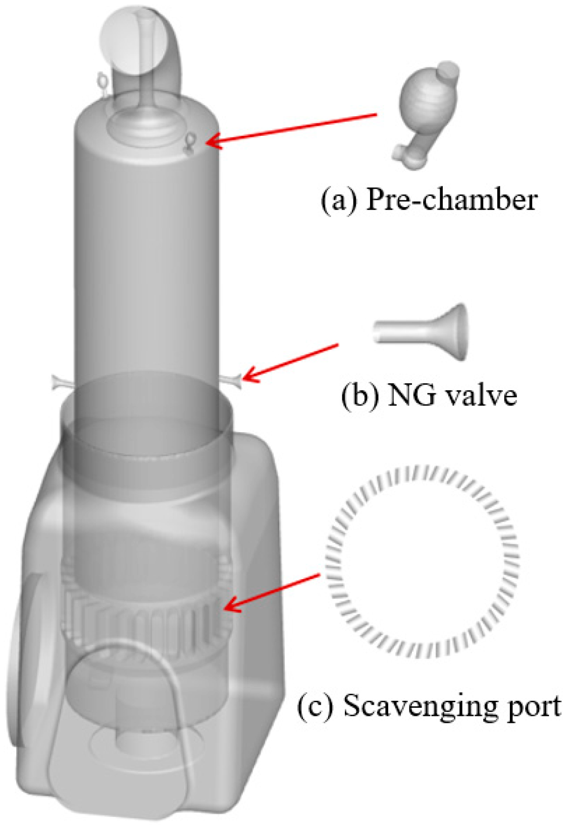
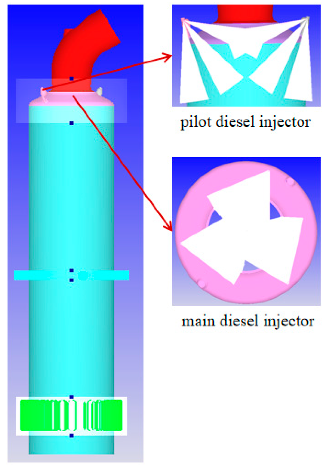
2.1. Computational Fluid Dynamics (CFD) Model

In this study, a CFD model was implemented within CONVERGE 3.0 to research the combustion process and engine performance of the X92DF engine, which is a two-stroke dual-fuel engine used in ultra-large container vessels. Further details regarding the main parameters of the engine are listed in Table 1. Figure 1 shows that the geometric model of the X92DF engine includes a scavenge box, cylinder, two NG nozzles, two pre-chambers, and an exhaust port. Meanwhile, the main diesel injection and flame jet formed by the pre-chamber flame jet were applied as the ignition strategies in this work. Therefore, three main diesel injectors are set on the cylinder head, and two pilot diesel injectors are set in the pre-chamber. The arrangements of the pilot injectors and main injectors are also shown in Figure 2.
The RNG k–ε model was adopted in this work, which has been validated to accurately simulate complex turbulent flow fields in the previous research literature for marine engines [26,27]. To accurately simulate the atomization process, the Kelvin-Helmholtz/Rayleigh-Taylor (KH-RT) model was used for calculating the process of spray atomization and breakup [28]. The SAGE model was applied in this study for calculating diesel/nature gas combustion, which has been widely applied in dual-fuel engines [23,29]. The extended Zeldovich NOx model was applied for calculating the emission in this work [30]. Meanwhile, the 100% load case has been selected for calibrating the model and further work, and the data of modeling inputs and pressure curves were obtained from the experiment. The temperature and pressure of the intake are 301.0 K and 4.7 bar. The temperature and pressure of the exhaust were set at 690 K and 4.55 bar, respectively. The initial temperature and pressure of the cylinder region were set at 930 K and 1.215 MPa. The mass of the main and pilot diesels was 16.8 g and 0.45 g per cycle. The start of injection timing and quantity of gas fuel were −118.8°CA and 151 g, respectively. The simulation starts before the exhaust valve is opened (90°CA) and runs throughout the cycle. The main boundaries and initial parameters are listed in Table 2.

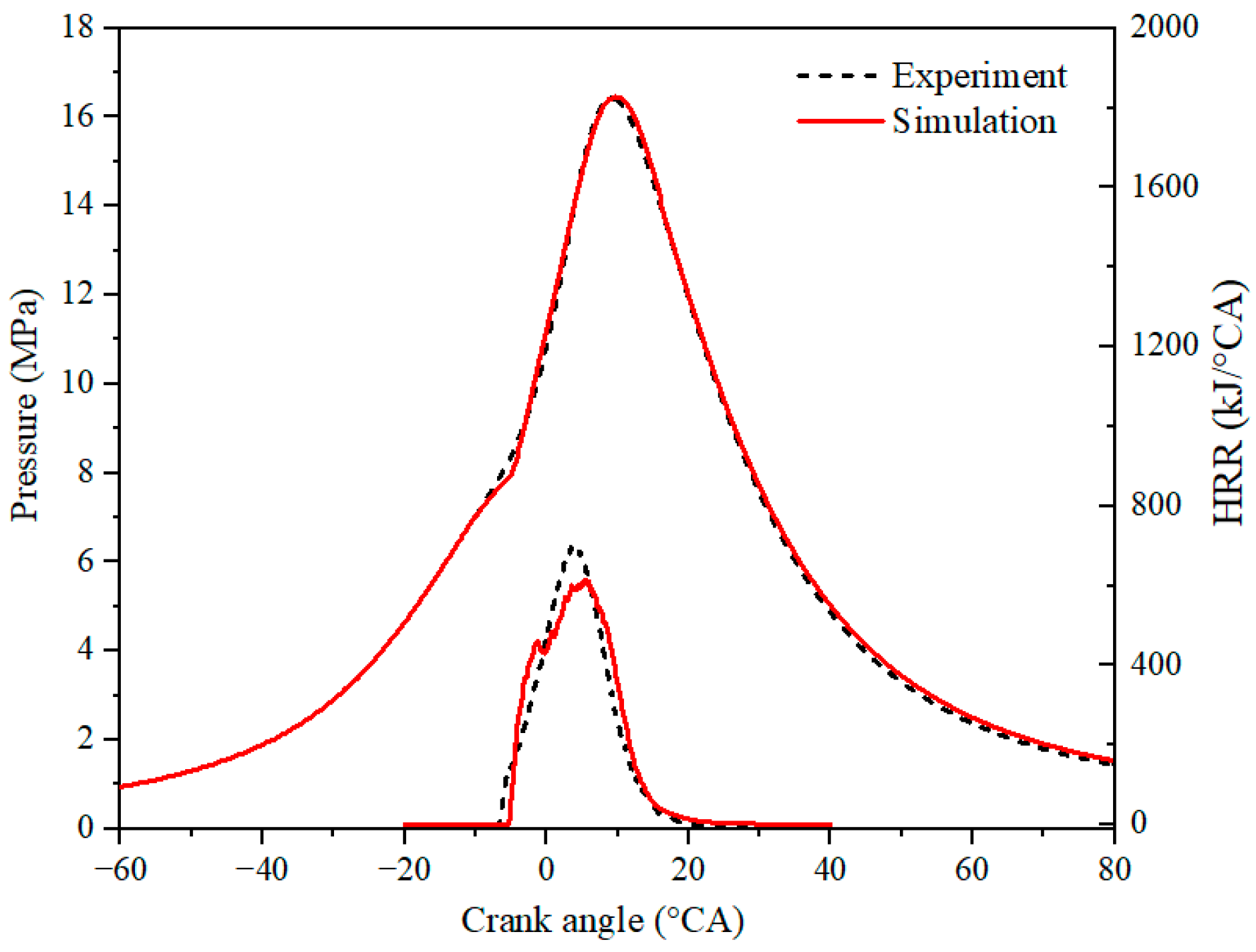
2.2. Model Validation

Figure 2 shows the mesh strategy used for simulating the ignition and combustion processes in this study. The model grid strategy includes the base grid, adaptive mesh refinement, and fixed embedding for the period of gas injection and combustion. To improve the accuracy of gas flow and combustion processes for simulating, the grid of the main component and important areas of the engine are embedded in the calculation process. Figure 3 shows that the compression and combustion pressure curves under a base grid of 0.04 m, 0.05 m, and 0.06 m. Figure 3 shows the effect of the base mesh size on the cylinder pressure was evident in the combustion process. With a decreasing grid size, the computational accuracy increased gradually. Considering the significant increase in computation time when using a finer grid, a base grid of 0.04 m is used to calculate compression and combustion in the cylinder. The spray model in this study has been validated in our previous research [31]. The reduced mechanism developed by Rahimi [32], which includes 76 chemical species and 464 reactions, has been extensively used for calculating cylinder pressure and emissions in dual-fuel engines [33]. Figure 4 shows a comparison between the experimental and calculated in-cylinder pressure and heat release rate (HRR) profiles. It can be seen that the error in average pressure is less than 3%, although the maximum difference occurs in the initial stage of combustion. Therefore, it is determined that the model established could be capable of simulating the compression and combustion processes within the cylinder accurately.

3. Results and Discussion

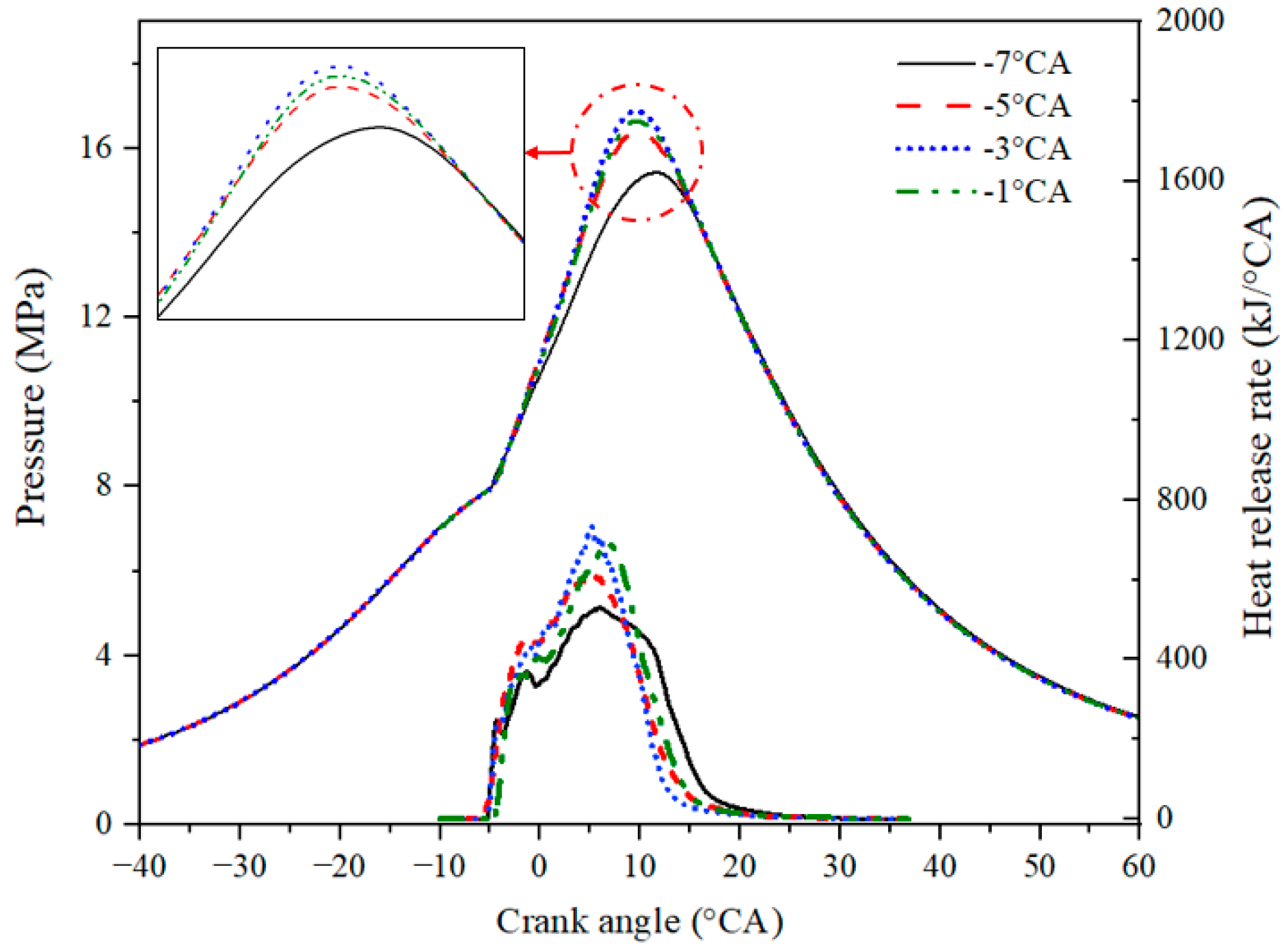
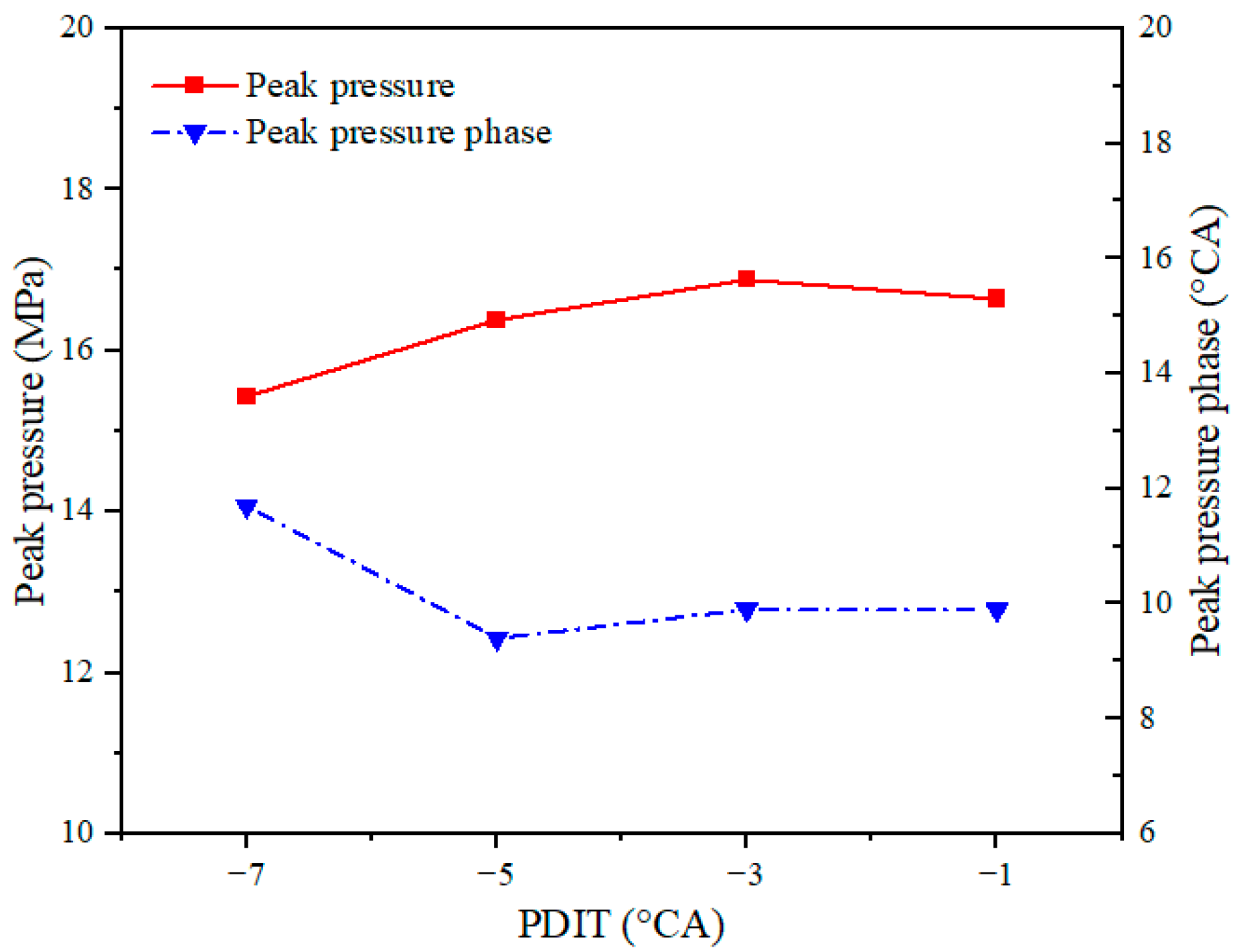
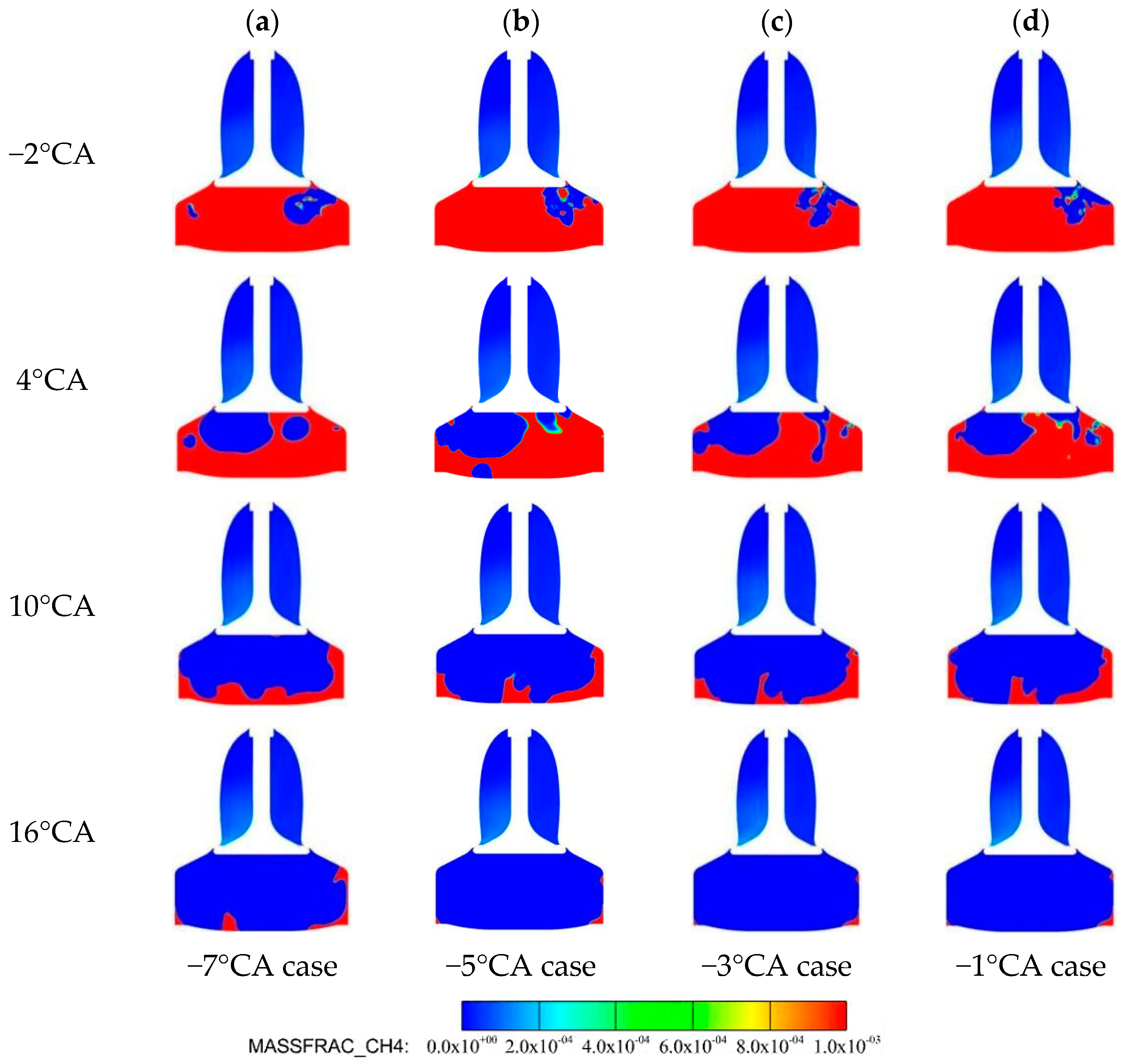
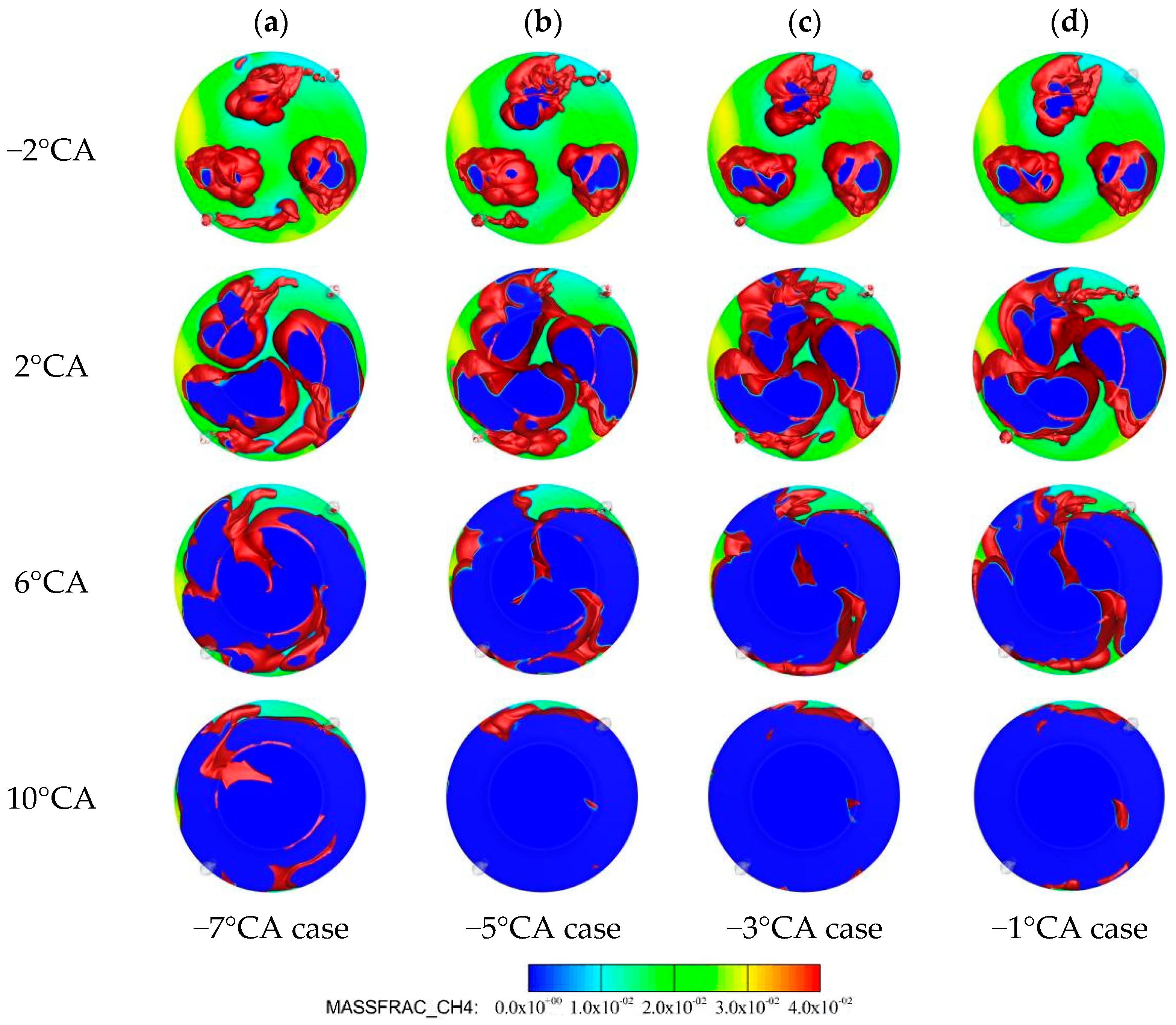
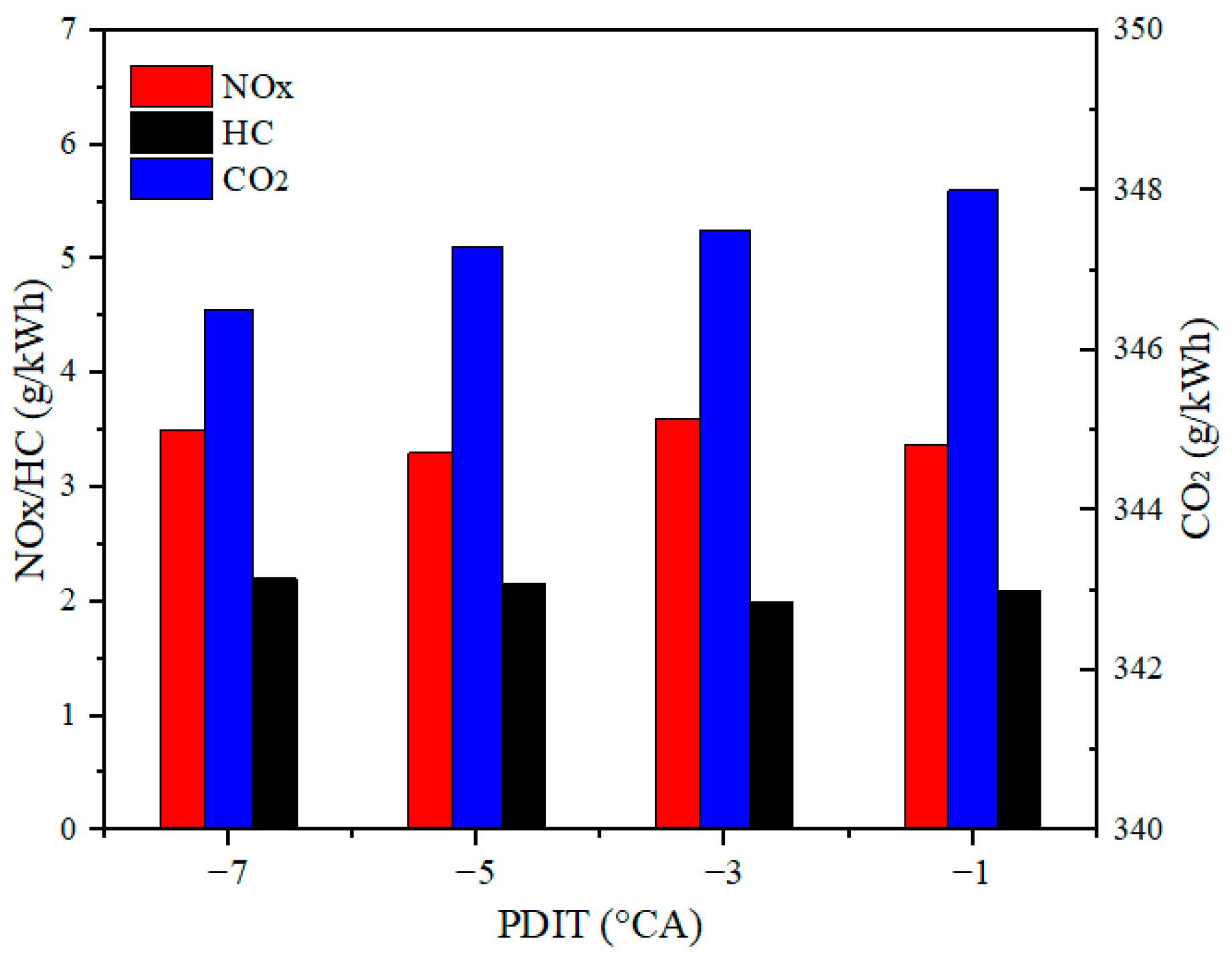
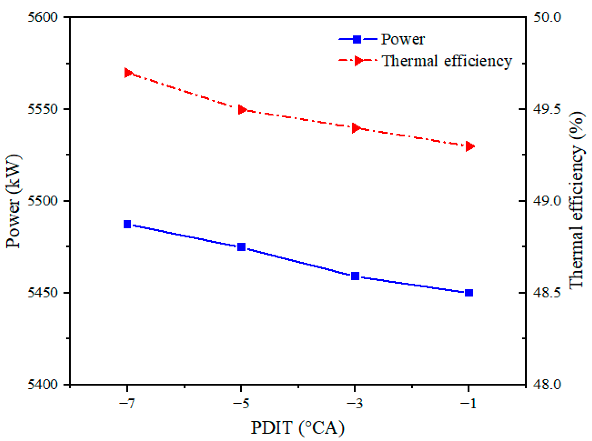
3.1. The Pilot Diesel Injection Timing

Although the quantity of diesel injection in the pre-chamber is 3% of the diesel and 0.28% of the total fuel, the injection timing of pilot diesel (PDIT) directly impacts the swirl movement and flame development. Therefore, in this section, the influence of PDIT on flame development and emissions under high loads is presented. During the analysis of the influence of different PDIT on combustion and emission, −9°CA, −7°CA, −4°CA, and −1°CA top dead center (TDC) was selected as the PDIT, and MDIT was fixed at −6°CA.
Figure 5 depicts the average pressure in the cylinder and HRR based on different PDITs. With the advance of PDIT, the maximum value of the pressure curve increases first and then decreases. When PDIT advances from −1°CA to −5°CA. the difference in the in-cylinder pressure curve between the different PDITs cases is decreases gradually. Meanwhile, Figure 6 shows that the maximum value of pressure first approaches the TDC and then away from the TDC, illustrating that the combustion rate increases when PDIT advances from −1°CA to −5°CA. Additionally, Figure 5 shows that the change in the heat release rate curves is resemblance to that of the average pressure in the cylinder. However, when PDIT is −7°CA, the average cylinder pressure and the peak HRR decrease compared to other cases. This is due to the fact that the timing of diesel injection of the main combustion chamber (−6°CA) is earlier than that of the pre-chamber, resulting in a short ignition delay period, and diesel is promoted to ignite the surrounding natural gas. However, because the quantity of pilot diesel was far less than that of main diesel, changing the PDIT had a comparatively small impact on the in-cylinder pressure, except that the PDIT is −7°CA.
Figure 7 depicts the distribution of in-cylinder CH4 under different PDITs. As observed in Figure 7a–d, the consumption rate of CH4 has no obvious differences with PDIT from −5°CA to −1°CA, except −7°CA. This means that PDIT has little effect on the combustion rate in the cylinder when PDIT approaches TDC, owing to the little diesel fuel from the pre-chamber. However, the area of unburned CH4 is larger than that of other cases, from −4°CA to 16°CA when PDIT is −7°CA. It indicates that PDIT is too early, making it difficult to ignite the surrounding NG under the condition of a small quantity of pilot diesel, which makes NG ignition slower and causes a decrease in the combustion pressure in the cylinder.
Figure 8a–d depicts the propagation of the flame and the distribution of CH4 in the cross-section of the cylinder under different PDITs. At −2°CA, the propagation of the jet flame formed by the pre-chamber in the cylinder increases with the advance of PDIT from −7°CA to −1°CA. Additionally, when PDIT is −7°CA, the area of the iso-surface is increased at 6°CA and 10°CA compared to other, different PDIT cases. This indicates that the combustion and consumption rate of CH4 are lower than those of the other cases, leading to lower in-cylinder pressure and peak HRR than those of the other PDIT cases. This is because when the pilot diesel of the pre-chamber is injected prematurely, the combustion performance of the main injection diesel bundle deteriorates owing to the absorption of too many combustion products formed by the jet flame.
Figure 9 shows the variations in the in-cylinder temperature and phase for different PDITs. The cylinder peak temperature first increases and then decreases as PDIT advances, which is less obvious than the difference in the average pressure in the cylinder. Meanwhile, Figure 9 also shows that the influence of PDIT on the maximal temperature coincides with the influence of the cylinder’s maximal pressure. However, when PDIT advanced from −1° to −7°, the advance of PDIT kept the maximal temperature away from the TDC, indicating that it was harmful to the organization of combustion in the cylinder as PDIT advanced too fast.
Figure 10 depicts that the quantity of NOx in the cylinder first increases and then decreases with the advance of PDIT in the range from −1°CA to −5°CA. This is mainly due to the fact that the temperature in the cylinder is the highest when PDIT is −3°CA, leading to the highest NOx emissions. However, NOx emissions increased when PDIT advanced from −5°CA to −7°CA. The main reason for this may be that although the in-cylinder temperature is lower than that of other PDIT cases, the HRR is higher than that of the other PDIT cases at the later stage of combustion, resulting in an increase in NOx emissions. As seen in Figure 10, the quantity of HC and CO2 changed slightly with the advancement of PDIT. The CO2 emissions decreased by 0.5 g/kWh. When the advance of PDIT is every 2°CA, illustrating that the advance of PDIT is beneficial to CO2 emissions reduction. In addition, the HC emissions have not shown any obvious change with the advance of PDIT, indicating that the consumption of in-cylinder CH4 is consistent as PDIT advances. Figure 11 shows that the power and thermal efficiency slightly increased with the advancement of PDIT. The power increased gradually from 5450 kW at −1°CA to 5487 kW at −7°CA. When PDIT changed from −1°CA to −7°CA, the thermal efficiency increased from 49.3% to 49.7%.

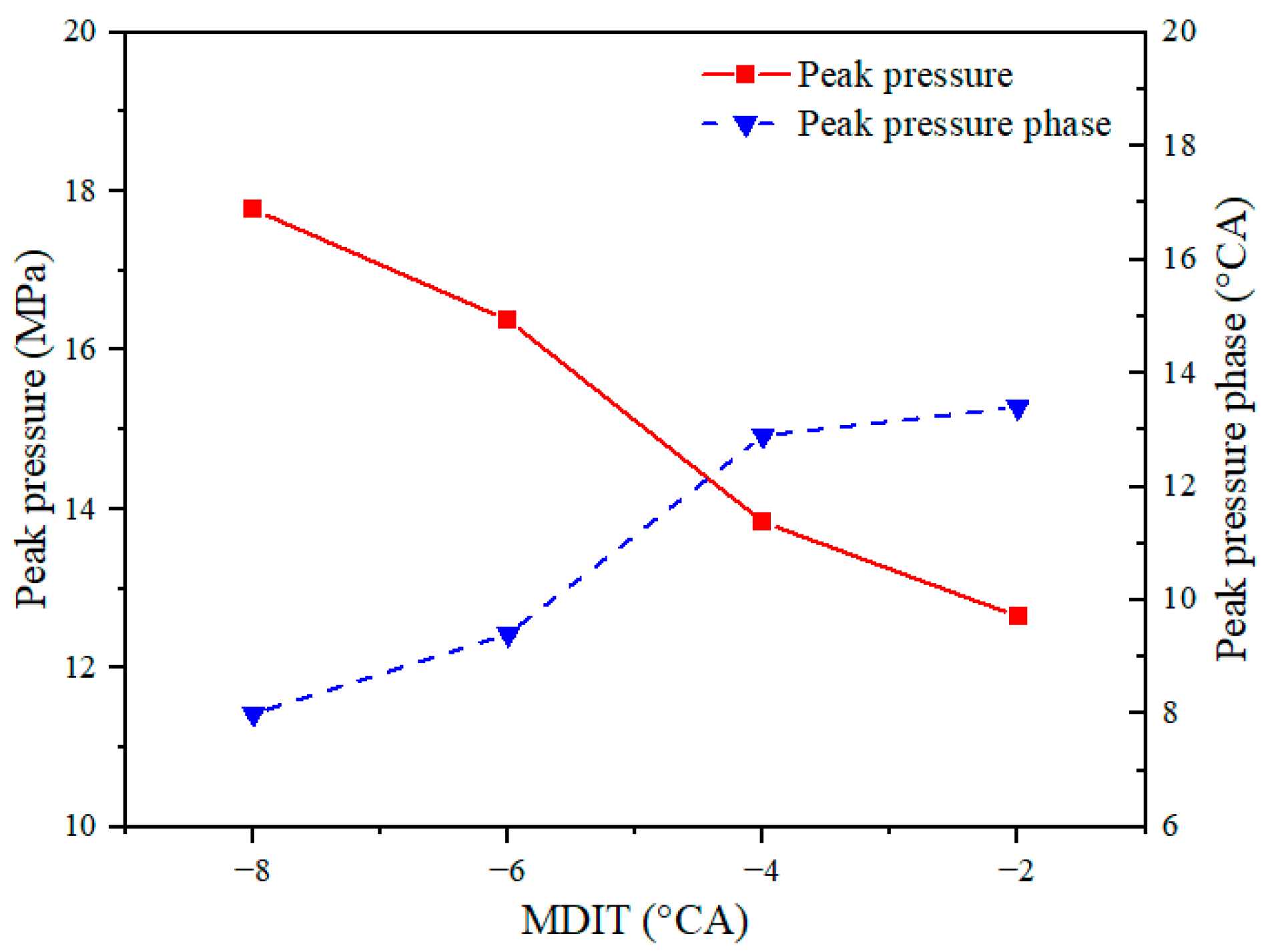
3.2. The Main Diesel Injection Timing

Owing to the quantity of diesel in the main combustion chamber, which accounts for 10% of the total fuel quantity and 97% of the total diesel, the injection timing of the main diesel injector has an important influence on the combustion process and engine performance. Therefore, in this section, the influence of MDIT on engine performance at high loads is presented. During the analysis of the influence of different injection times of the main injector on combustion and emission, −8°CA, −6°CA, −4°CA, and −2°CA were selected as the start of MDIT, and the start of PDIT was fixed at −5°CA.
Figure 12 shows the changes in the mean pressure and HRR curves for different MDITs. As depicted in Figure 12, the cylinder maximum pressure increases and approaches TDC as MDIT advances. This is because the quantity of the mixture deteriorated before TDC when MDIT was retarded, resulting in less fuel burning before TDC and lower in-cylinder pressure. Moreover, the change in the heat release rate curves bears resemblance to that of the mean pressure in the cylinder, and the peak HRR increased significantly as MDIT advanced from −4°CA to −6°CA, indicating that earlier ignition increases flame propagation in the cylinder. Furthermore, as depicted in Figure 13, the advance of MDIT led to an increase in the pressure peak and a decrease in the combustion phase, illustrating that the combustion rate is faster with the advance of MDIT from −2°CA to −8°CA.
Figure 14 depicts the distribution of in-cylinder CH4 under different MDITs. As shown in Figure 14a–d, the consumption rate of CH4 accelerated with the advancement of MDIT, and CH4 was consumed from the center to the wall and bottom of the cylinder. With the delay in MDIT, the flame propagation speed decreases and the combustion duration increases. Meanwhile, MDIT was delayed, leading to the CH4 in the cylinder increasing after the end of combustion. Therefore, CH4 emissions are reduced by the advancement of MDIT.
To analyze the influence of different MDITs on the in-cylinder combustion process, the effect of the flame jet generated by the main diesel and pre-chamber on the flame propagation and the consumption of CH4 were analyzed in depth. Figure 15 shows the distribution of the temperature iso-surface at T = 1400 K and the distribution of CH4 in the Z-direction in the cylinder. As shown in Figure 15a–d, the area of the temperature iso-surface formed by the main diesel increases with the advancement of MDIT at −2°CA, indicating that the flame propagation in the cylinder mainly results from the main diesel burned and the combustion rate is improved as MDIT advances. Furthermore, it can be seen that the jet flame formed by the pre-chambers ignites the CH4 on the cross-section of the cylinder after 2°CA, indicating that the propagation rate of the flame from the pre-chambers is lower than that from the main diesel. Therefore, it can be concluded that the CH4 in the cylinder was mainly ignited by the main diesel.
Figure 16 shows the variation in the mean temperature in the cylinder for different MDITs. As depicted in Figure 16, the in-cylinder peak temperature significantly increases as MDIT advances and increases by 0.7% as MDIT advances every 2°CA. Additionally, the MDIT advance caused the maximal temperature in the curve move to TDC, indicating the combustion rate is increased and the entire combustion stage is completed before TDC. Meanwhile, as shown in the red circle enlarged plot in Figure 16, the combustion duration was extended owing to the delay in ignition when MDIT was delayed, leading to a rise in the mean temperature after the TDC.
Figure 17 shows the variations in HC, NOx, and CO2 emissions under different MDITs. As observed from Figure 17, the quantity of HC in the cylinder decreased gradually between −8°CA and −2°CA as MDIT advanced, leading to an increase in the maximal pressure and an improvement in the combustion process. However, as the temperature is highest when MDIT is −8°CA, excessive cylinder temperature may result in increasing NOx emissions and the NOx emissions increased by 0.7 g/kWh. Meanwhile, the advancement of MDIT leads to the increase in CO2 emissions, which increased by 10.5 g/kWh from −2°CA to −8°CA. The result illustrates that the advancement of MDIT is harmful to CO2 emission reduction. Figure 18 shows the power and thermal efficiencies of different MDITs. As observed in Figure 18, the engine power improved by degrees from 5200 kW to 5516 kW as MDIT advanced, and the engine power improved by 316 kW from −2°CA to −8°CA. The thermal efficiency improved from 48.7% to 50.2% with the advancement of MDIT.

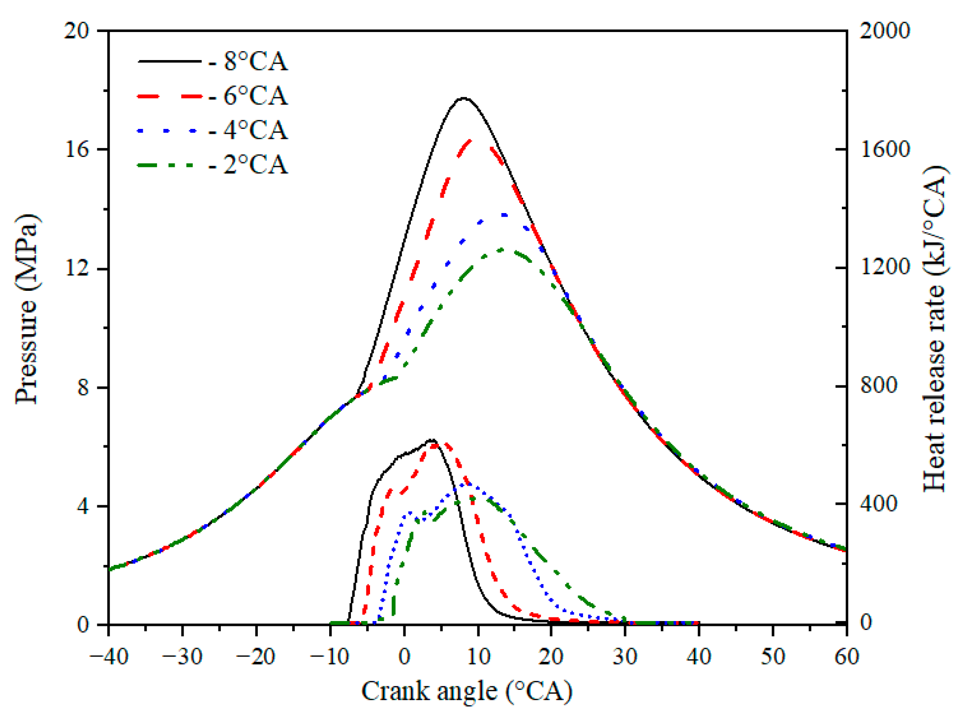
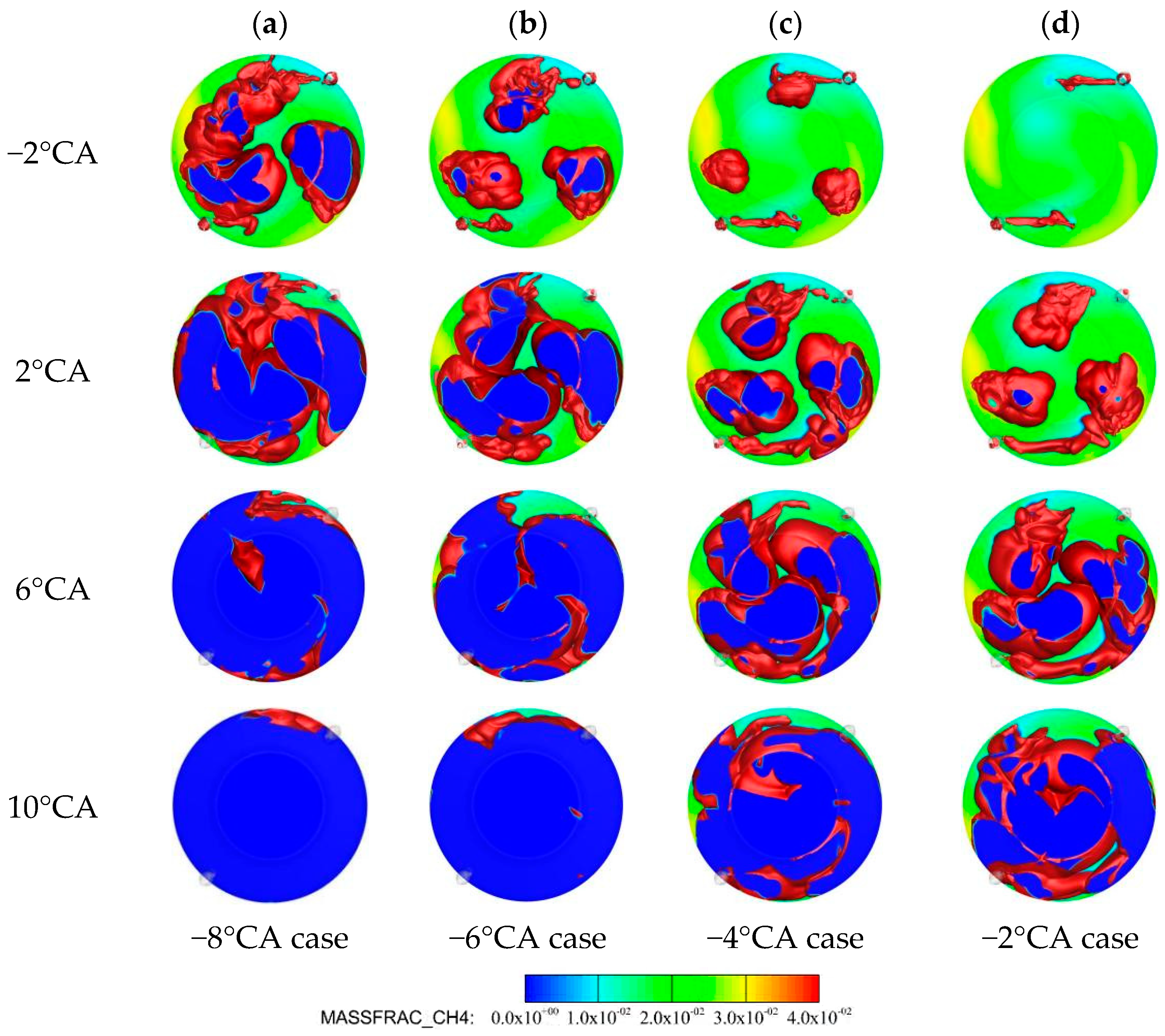
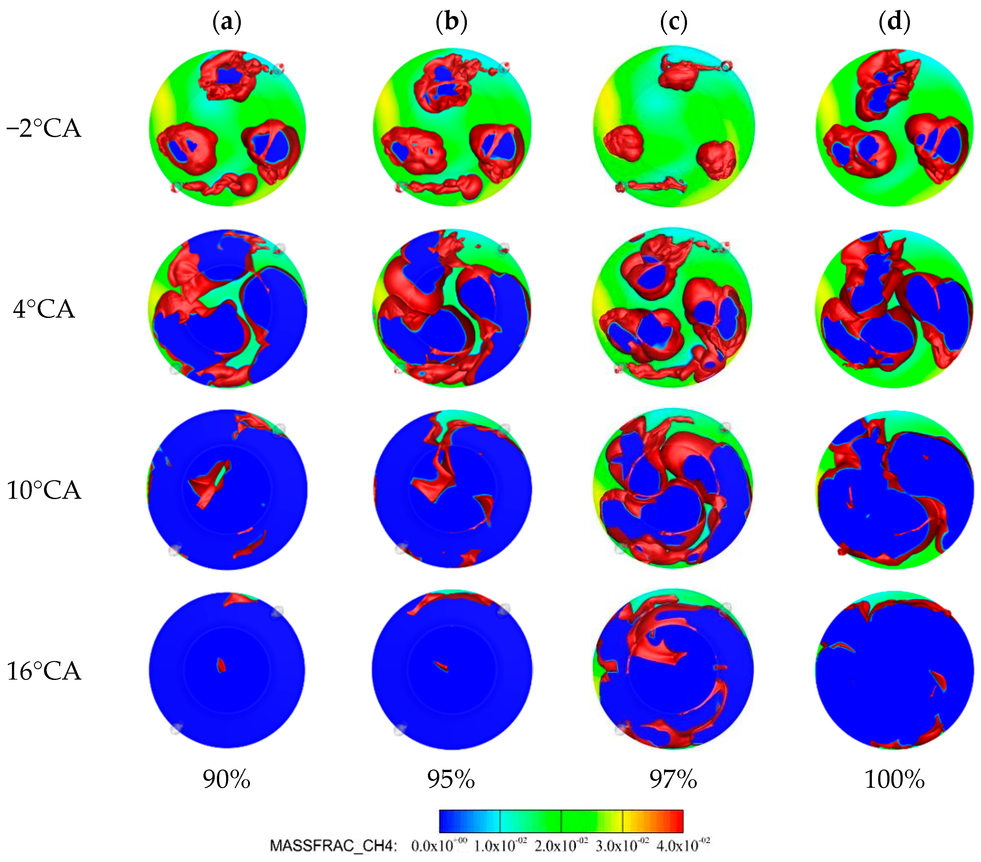
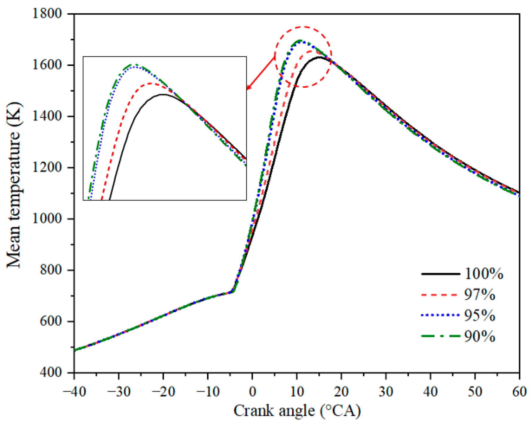
3.3. The Ratio of Main and Pilot Diesel

In this section, the effects of the proportion of the ratio of different main diesel and pilot diesel on the flame propagation and combustion process are analyzed. During the analysis of the influence of different main diesel ratios (MDRs) on combustion and emissions, 90%, 95%, 97%, and 100% of the total diesel were selected as the proportion of the main diesel, and the proportion of the pilot decreased correspondingly. In all calculative cases, the quantity of nature gas and total diesel remained unchanged.
The variations in cylinder average pressure and HRR for different MDRs are depicted in Figure 19. As observed in Figure 19, as MDR decreases from 100% to 95%, the in-cylinder maximum pressure increases significantly from 15.8 MPa to 17.55 MPa, and the combustion phasing advances. The peak pressure and phase with different MDRs are shown in Figure 20. Furthermore, the ratio of main diesel decreased from 100% to 95%. The range of pressure change in the cylinder was greater than that in the range of 95–90%, indicating that the combustion of nature gas in the cylinder has an obvious influence when the MDR is high. Meanwhile, the HRR curves show that MDR is lower than 95%, which is not conducive to the formation of jet flames and the development of the cylinder, as the MDR is too little to make the mixture concentration of the pre-chamber too high.
Figure 21a–d show that with an increase in the MDR, the consumption rate of CH4 is increased and the duration is gradually decreased. Meanwhile, the distribution of in-cylinder CH4 in the case of 90% has no obvious difference compared to the case of 95%. The main reason for this is that the quantity of diesel in the pre-chamber increases with a decrease in the proportion of the main diesel. Thus, it can be deduced that the influence of the pilot diesel on the jet flame formed by the pre-chamber and nature gas combustion are suppressed by the quantity of diesel in the pre-chamber.
Figure 22a–d show that the 1400 K iso-surface of the flame formed by the main diesel gradually decreased in the cylinder as the MDR decreased at −2°CA, indicating that the ignition area caused by diesel combustion is increased and the flame propagation rate of the nature gas is faster. Meanwhile, it can be observed from the flame propagation that the flame surface formed by a part of the flame jet formed by the pilot diesel and the main diesel injection has a certain interference at the upper end of the slice. This explains why the flame formation and propagation in the main combustion chamber are affected by the time interval between the main and pilot diesel injections at different injection timings.
Figure 23 shows the variations in in-cylinder temperature and phase for different MDRs. The in-cylinder mean temperature increased gradually, and the time of the maximum temperature advanced towards the TDC with a decrease in the MDR, which was beneficial for completing the entire combustion process approach to the TDC. Meanwhile, the amplitude of the variation in the peak temperature phase was larger in the range of 97% to 95% compared to the range from 95% to 90%. Figure 24 shows that the HC emission in the cylinder gradually increased with an increase in the MDR, indicating that the level of swirl movement was lower owing to the flame area of the jet formed by the pre-chamber decreasing, which led to a reduction in the rate of combustion and incomplete combustion. Furthermore, NOx emissions in the cylinder decreased first and then increased with the decrease in the MDR, which has an obvious difference for different MDRs compared to the HC emissions. The main reason for this was that an increase in the pilot diesel ratio enhanced the combustion rate and led to a higher mean temperature, resulting in an increase in NOx emissions in the combustion process. In addition, the CO2 emissions decreased by 4 g/kWh when the MDR decreased from 100% to 90%, which suggests that the decrease in the MDR is beneficial to CO2 emissions reduction.
Figure 25 shows the power and thermal efficiencies for different MDRs. The engine power improved by degrees from 5450 kW to 5500 kW as MDR decreased from 100% to 90%. Additionally, the thermal efficiency improved from 49.5% to 50.1% as MDR decreased. This indicates that changing the ratio of the main diesel has a significant effect on engine performance, although it has no obvious change when MDR is beyond 95%.

4. Conclusions

In this work, the effects of the injection strategy of diesel direct injection combined with diesel jet flame on the ignition and combustion of natural gas in a large-bore two-stroke marine engine were investigated. The main conclusions are as follows:
  • The difference in injection time and quantity affected the development process of the main injection flame and jet flame formed by the pilot diesel. We found that the change in the main diesel in the main combustion parameters had a greater influence on combustion, emission, and power than that of the pilot diesel in the pre-chamber.
  • Changing PDIT has a smaller effect on engine performance when PDIT advances from −1°CA to −5°CA. However, when PDIT is −7°CA, the peak pressure and consumption rate of CH4 decreases. This is because it is difficult to ignite the gas in the cylinder rapidly using the jet flame formed by the pre-chamber with a small quantity of diesel, leading to slow propagation of the flame in the cylinder and deterioration of combustion.
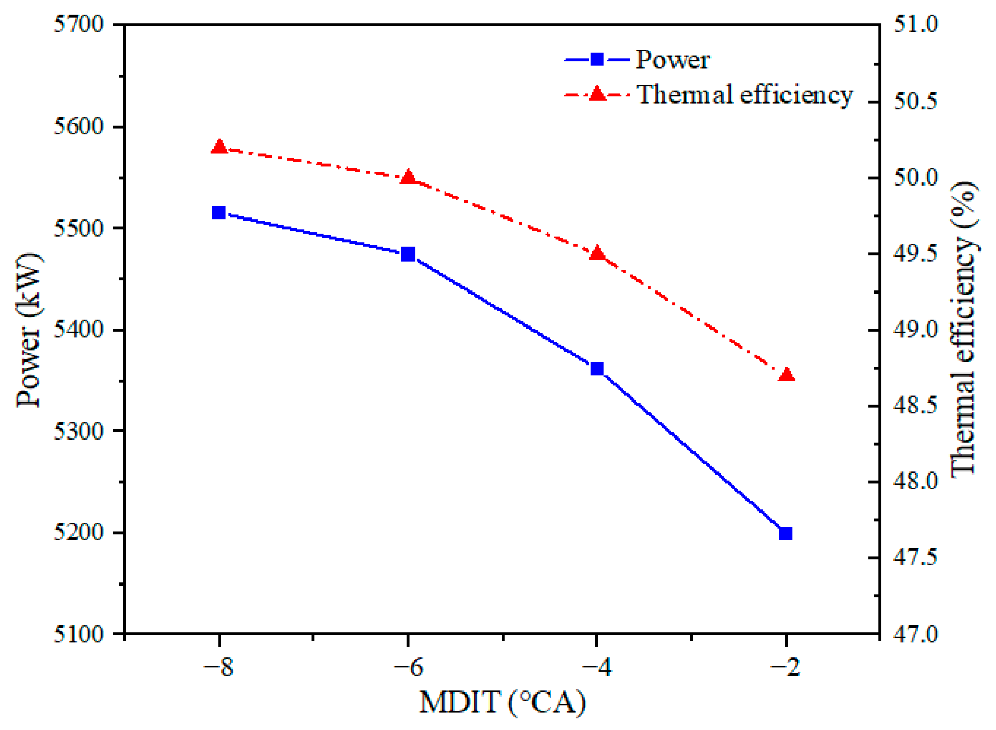
  • With the advance in MPIT, the peak pressure increased, and the consumption rate of CH4 accelerated. Meanwhile, the unburned CH4 and HC emissions in the cylinder reduced as MDIT advanced, leading to an increase in engine power by 316 kW, and the thermal efficiency improved by 1.5% when MPIT advanced from −8°CA to −2°CA. However, CO2 emissions increased by 10.5 g/kWh, and NOx emissions increased by 0.7 g/kWh.
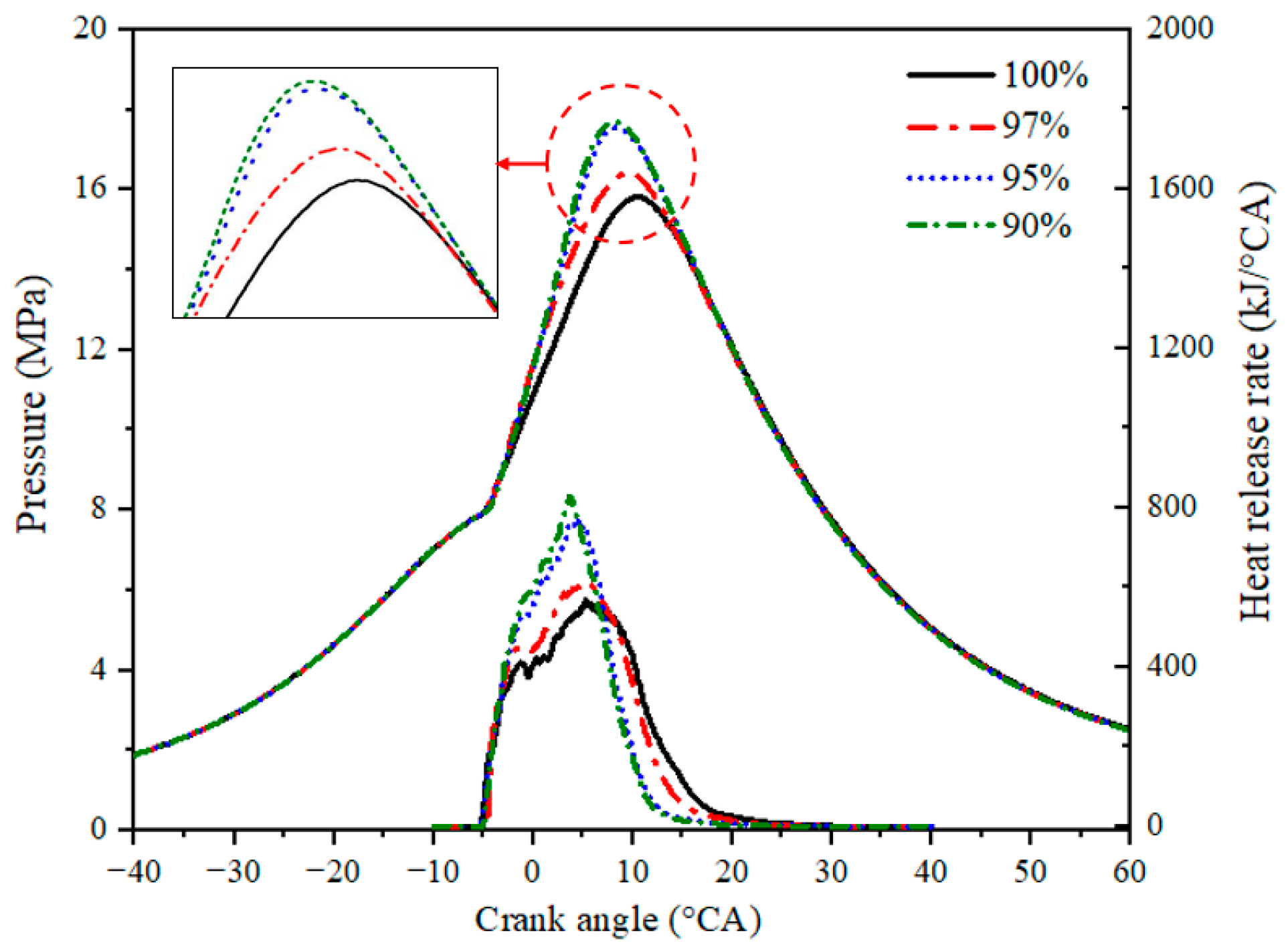
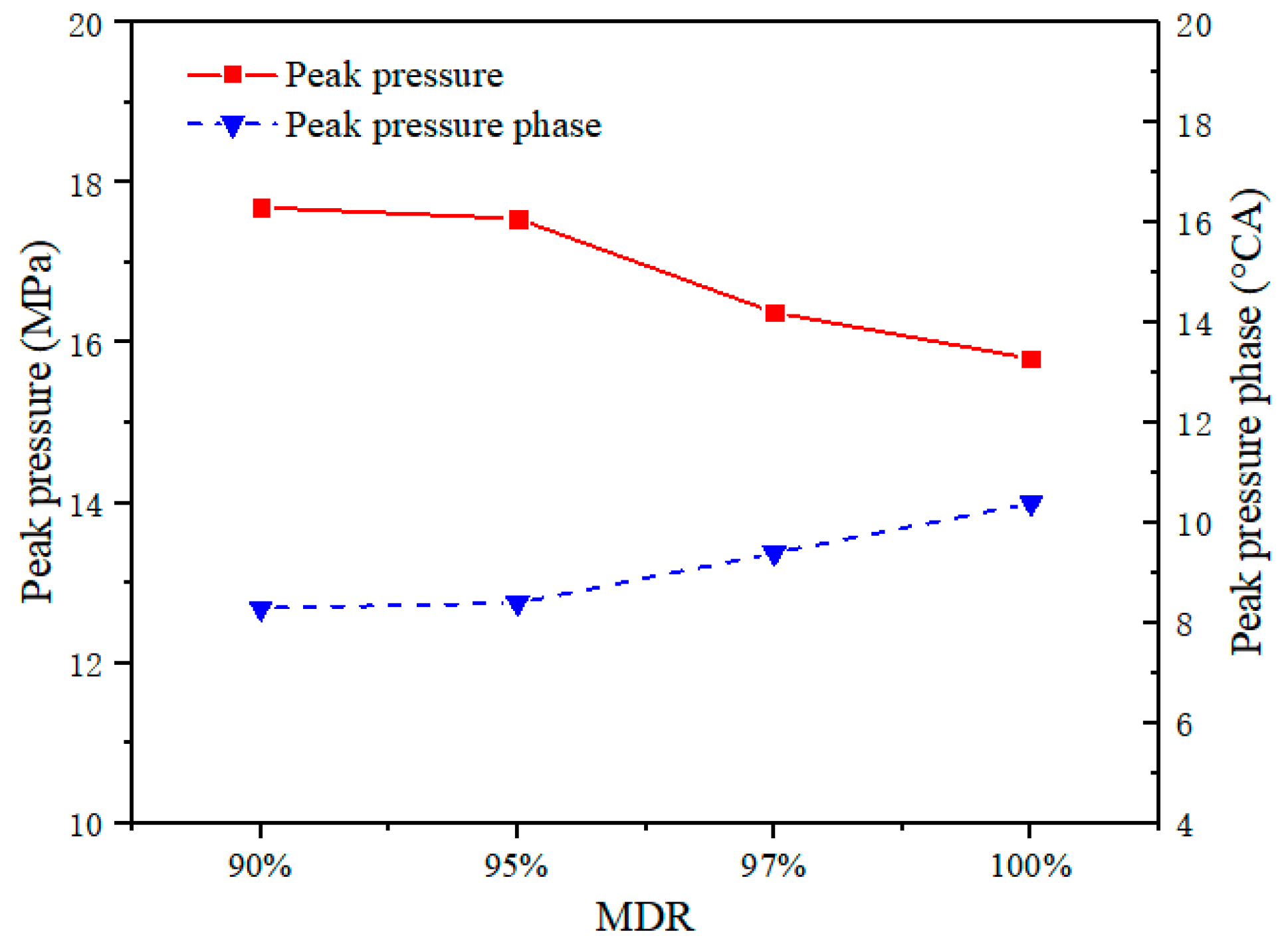
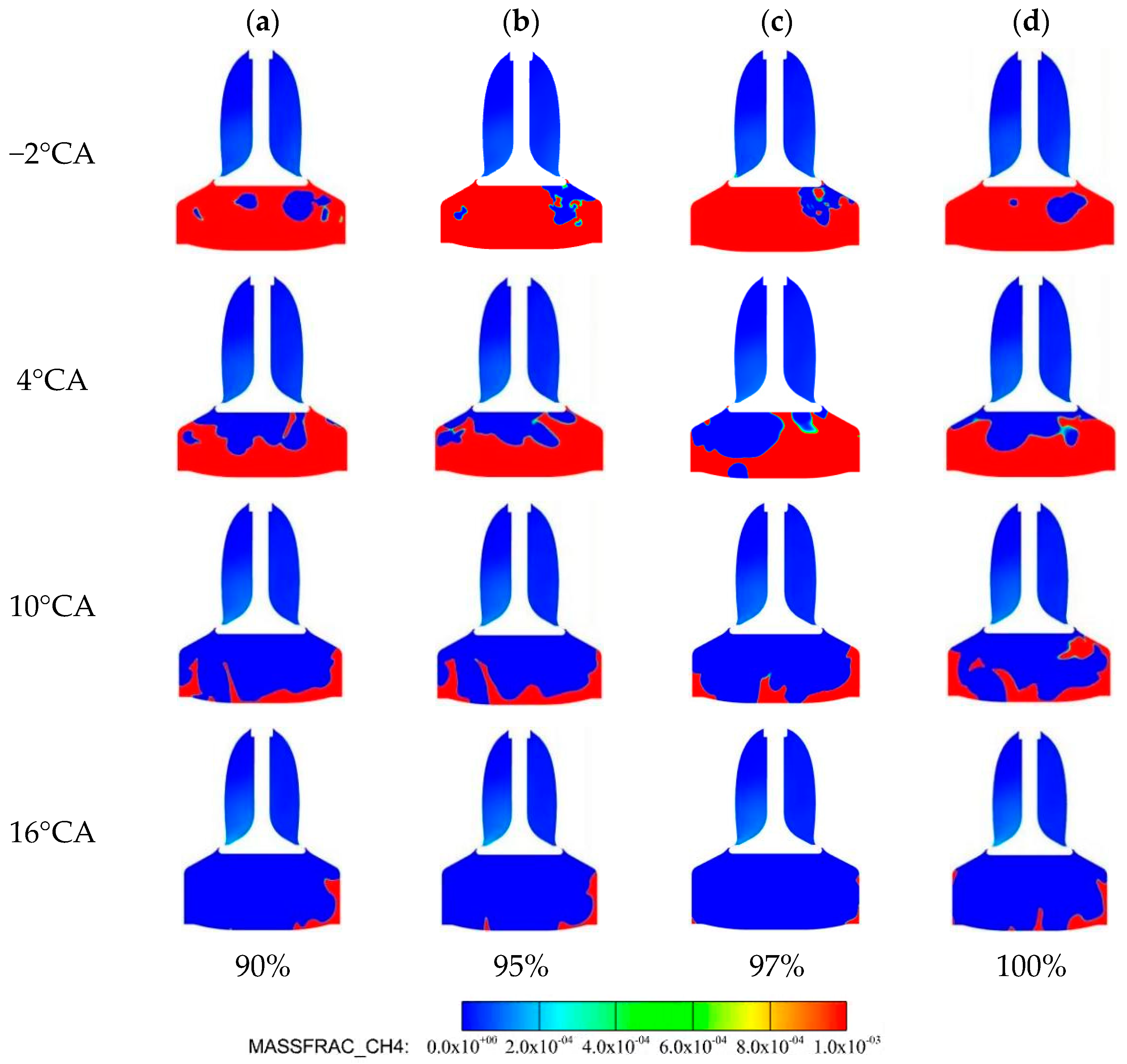
  • As the main diesel ratio decreased from 100% to 90%, the maximum pressure and combustion rate of CH4 increased. Meanwhile, the engine power improved by 50 kW and the thermal efficiency improved by 0.6% as the decrease in main diesel from 100% to 90%, leading to HC emissions decreased. The CO2 emissions decreased by 4 g/kWh when MDR decreased. However, the NOx emissions decreased first and increased then with the decrease in MDR, which has no obvious change.

Author Contributions

Conceptualization, L.L. and S.L.; funding acquisition, L.L. and D.L.; investigation, S.L.; methodology, S.L.; software, S.L.; writing—original draft preparation, S.L.; writing—review and editing, L.L. and D.L.; supervision, L.L. and D.L.; All authors have read and agreed to the published version of the manuscript.

Funding

This research was funded by the National Key Research and Development Program (2022YFB3504104), High-Tech Ship Scientific Research Project of the Ministry of Industry and Information Technology (CBG5N21-1-1).

Institutional Review Board Statement

Not applicable.

Informed Consent Statement

Not applicable.

Data Availability Statement

All data generated or analyzed during this study are included in this published article.

Conflicts of Interest

The authors declare no conflicts of interest.

Abbreviations

3-DThree-Dimensional
CFDComputational Fluid Dynamics
CH4Methane
CO2Carbon Dioxide
DFDual Fuel
IMOInternational Maritime Organization
LNGLiquefied Natural Gas
MDITInjection Timing of Main Diesel
MDRMain Diesel Ratio
NGNatural Gas
NOxNitrogen Oxides
PDITInjection Timing of Pilot Diesel
TDCTop Dead Center

References

  1. Xing, H.; Spence, S.; Chen, H. A comprehensive review on countermeasures for CO2 emissions from ships. Renew. Sustain. Energy Rev. 2020, 134, 110222. [Google Scholar] [CrossRef]
  2. IMO. Fourth Greenhouse Gas Study 2020; International Maritime Organization: London, UK, 2020. [Google Scholar]
  3. Serra, P.; Fancello, G. Towards the IMO’s GHG Goals: A Critical Overview of the Perspectives and Challenges of the Main Options for Decarbonizing International Shipping. Sustainability 2020, 12, 3220. [Google Scholar] [CrossRef]
  4. IMO. Greenhouse Gas Emissions; International Maritime Organization: London, UK, 2018. [Google Scholar]
  5. Karczewski, M.; Chojnowski, J.; Szamrej, G. A Review of Low-CO2 Emission Fuels for a Dual-Fuel RCCI Engine. Energies 2021, 14, 5067. [Google Scholar] [CrossRef]
  6. Ampah, J.D.; Yusuf, A.A.; Afrane, S.; Jin, C.; Liu, H. Reviewing two decades of cleaner alternative marine fuels: Towards IMO’s decarbonization of the maritime transport sector. J. Clean. Prod. 2021, 320, 128871. [Google Scholar] [CrossRef]
  7. Elkafas, A.G.; Elgohary, M.M.; Shouman, M.R. Numerical analysis of economic and environmental benefits of marine fuel conversion from diesel oil to natural gas for container ships. Environ. Sci. Pollut. Res. 2021, 28, 15210–15222. [Google Scholar] [CrossRef]
  8. Fernández, I.A.; Gómez, M.R.; Gómez, J.R.; Insua, Á.B. Review of propulsion systems on LNG carriers. Renew. Sustain. Energy Rev. 2017, 67, 1395–1411. [Google Scholar] [CrossRef]
  9. Degiuli, N.; Martić, I.; Farkas, A.; Gospić, I. The impact of slow steaming on reducing CO2 emissions in the Mediterranean Sea. Energy Rep. 2021, 7, 8131–8141. [Google Scholar]
  10. Iannaccone, T.; Landucci, G.; Tugnoli, A.; Salzano, E.; Cozzani, V. Sustainability of cruise ship fuel systems: Comparison among LNG and diesel technologies. J. Clean. Prod. 2020, 260, 121069. [Google Scholar] [CrossRef]
  11. Duan, X.; Liu, J.; Yao, J.; Chen, Z.; Wu, C.; Chen, C.; Dong, H. Performance, combustion and knock assessment of a high compression ratio and lean-burn heavy-duty spark-ignition engine fuelled with n-butane and liquefied methane gas blend. Energy 2018, 158, 256–268. [Google Scholar] [CrossRef]
  12. Mavrelos, C.; Gerasimos, T. Numerical investigation of a premixed combustion large marine two-stroke dual fuel engine for optimising engine settings via parametric runs. Energy Convers. Manag. 2018, 160, 48–59. [Google Scholar] [CrossRef]
  13. Ju, D.; Huang, Z.; Li, X.; Zhang, T.; Cai, W. Comparison of open chamber and pre-chamber ignition of methane/air mixtures in a large bore constant volume chamber: Effect of excess air ratio and pre-mixed pressure. Appl. Energy 2020, 260, 114319. [Google Scholar] [CrossRef]
  14. Simpson, D.J.; Olsen, D.B. Precombustion Chamber Design for Emissions Reduction from Large Bore NG Engines. J. Eng. Gas Turbines Power 2010, 132, 122802. [Google Scholar] [CrossRef]
  15. Shin, J.; Choi, J.; Seo, J.; Park, S. Pre-chamber combustion system for heavy-duty engines for operating dual fuel and diesel modes. Energy Convers. Manag. 2022, 255, 115365. [Google Scholar] [CrossRef]
  16. Zhou, L.; Song, Y.; Hua, J.; Liu, F.; Liu, Z.; Wei, H. Effects of different hole structures of pre-chamber with turbulent jet ignition on the flame propagation and lean combustion performance of a single-cylinder engine. Fuel 2022, 308, 121902. [Google Scholar] [CrossRef]
  17. Guan, W.; He, Z.; Zhang, L.; EL-Seesy, A.; Wen, L.; Zhang, Q.; Yang, L. Effect of asymmetric structural characteristics of multi-hole marine diesel injectors on internal cavitation patterns and flow characteristics: A numerical study. Fuel 2021, 283, 119324. [Google Scholar] [CrossRef]
  18. Li, M.; Zhang, Q.; Li, G.; Shao, S. Experimental investigation on performance and heat release analysis of a pilot ignited direct injection natural gas engine. Energy 2015, 90, 251–1260. [Google Scholar] [CrossRef]
  19. Yousefi, A.; Guo, H.; Birouk, M.; Liko, B.; Lafrance, S. Effect of pre-main-post diesel injection strategy on greenhouse gas and nitrogen oxide emissions of natural gas/diesel dual-fuel engine at high load conditions. Fuel 2021, 302, 121110. [Google Scholar] [CrossRef]
  20. Cong, Y.; Gan, H.; Wang, H. Parameter investigation of the pilot fuel post-injection strategy on performance and emissions characteristics of a large marine two-stroke natural gas-diesel dual-fuel engine. Fuel 2022, 323, 124404. [Google Scholar] [CrossRef]
  21. Liu, Z.; Zhou, L.; Liu, B.; Zhao, W.; Wei, H. Effects of equivalence ratio and pilot fuel mass on ignition/extinction and pressure oscillation in a methane/diesel engine with pre-chamber. Appl. Therm. Eng. 2019, 158, 113777. [Google Scholar] [CrossRef]
  22. Liu, L.; Wu, Y.; Wang, Y. Numerical investigation on knock characteristics and mechanism of large-bore natural gas dual-fuel marine engine. Fuel 2022, 310, 122298. [Google Scholar] [CrossRef]
  23. Wang, H.; Gan, H.; Theotokatos, G. Parametric investigation of pre-injection on the combustion, knocking and emissions behavior of a large marine four-stroke dual-fuel engine. Fuel 2020, 281, 118744. [Google Scholar] [CrossRef]
  24. Guo, H.; Zhou, S.; Zou, J.; Shreka, M. A Numerical Study on the Pilot Injection Conditions of a Marine 2-Stroke Lean-Burn Dual Fuel Engine. Processes 2020, 8, 1396. [Google Scholar] [CrossRef]
  25. Tang, Q.; Ramgopal, S.; Manuel, E.M.; Priybrat, S.; Ponnya, H.; Moez, B.H.; Emre, C.; Junseok, C.; Gaetano, M.; Bengt, J. Optical diagnostics on the pre-chamber jet and main chamber ignition in the active pre-chamber combustion (PCC). Combust. Flam 2021, 228, 218–235. [Google Scholar] [CrossRef]
  26. Cao, Z.; Wang, T.; Sun, K.; Cui, L.; Gui, Y. Numerical Analysis of Scavenging Process in a Large Marine Two-Stroke Diesel Engine; SAE Technical Paper 2017-01-2201; SAE International: Warrendale, PA, USA, 2017. [Google Scholar]
  27. Wang, G.; Yu, W.; Li, X.; Su, Y.; Yang, R.; Wu, W. Experimental and numerical study on the influence of intake swirl on fuel spray and in-cylinder combustion characteristics on large bore diesel engine. Fuel 2019, 237, 209–221. [Google Scholar] [CrossRef]
  28. Patterson, M.A.; Reitz, R.D. Modeling the effects of fuel spray characteristics on diesel engine combustion and emission. SAE Trans. 1998, 107, 27–43. [Google Scholar]
  29. Zhu, L.; Li, B.; Li, A.; Ji, W.; Qian, Y.; Lu, X.; Huang, Z. Effects of fuel reforming on large-bore low-speed two-stroke dual fuel marine engine combined with EGR and injection strategy. Int. J. Hydrog. Energy 2020, 45, 29505–29517. [Google Scholar] [CrossRef]
  30. Özgül, E.; Şimşek, M.; Bedir, H. Use of thermodynamical models with predictive combustion and emission capability in virtual calibration of heavy duty engines. Fuel 2020, 264, 116744. [Google Scholar] [CrossRef]
  31. Liu, L.; Liu, S.; Xia, Q.; Liu, B.; Ma, X. Numerical Investigation on Mixing Characteristics and Mechanism of Natural Gas/Air in a Super-Large-Bore Dual-Fuel Marine Engine. Atmosphere 2022, 13, 1528. [Google Scholar] [CrossRef]
  32. Rahimi, A.; Fatehifar, E.; Saray, R.K. Development of an optimized chemical kinetic mechanism for homogeneous charge compression ignition combustion of a fuel blend of n-heptane and natural gas using a genetic algorithm. Proc. Instit. Mech. Eng. Part D J. Automob. Eng. 2010, 224, 1141–1159. [Google Scholar] [CrossRef]
  33. Liu, H.; Li, J.; Wang, J.; Wu, C.; Liu, B.; Dong, J.; Liu, T.; Ye, Y.; Wang, H.; Yao, M. Effects of injection strategies on low-speed marine engines using the dual fuel of high-pressure direct-injection natural gas and diesel. Energy Sci. Eng 2019, 7, 1994–2010. [Google Scholar] [CrossRef]
Figure 1. Three-dimensional geometric structure.
Jmse 12 00857 g001
Figure 2. Mesh refinement regions.
Jmse 12 00857 g002
Figure 3. The effect of the grid on the pressure.
Jmse 12 00857 g003
Figure 4. Cylinder pressure and HRR of the simulation and experiment.
Jmse 12 00857 g004
Figure 5. Mean pressure and HRR in the cylinder for different PDITs.
Jmse 12 00857 g005
Figure 6. Peak pressure and phase for different PDITs.
Jmse 12 00857 g006
Figure 7. Distribution of CH4 along the Y-direction for different PDITs.
Jmse 12 00857 g007
Figure 8. Iso-surface temperature of 1400 K and CH4 distribution along Z-direction for different PDITs.
Jmse 12 00857 g008
Figure 9. Mean temperature for different PDITs.
Jmse 12 00857 g009
Figure 10. NOx, HC/CO2 emissions for different PDITs.
Jmse 12 00857 g010
Figure 11. The power and thermal efficiency for different PDITs.
Jmse 12 00857 g011
Figure 12. Mean pressure and HRR for different MDITs.
Jmse 12 00857 g012
Figure 13. Peak pressure and phase for different MDITs.
Jmse 12 00857 g013
Figure 14. Distribution of CH4 along the Y-direction for different MDITs.
Jmse 12 00857 g014
Figure 15. Iso-surface temperature of 1400 K and CH4 distribution along Z-direction for different MDITs.
Jmse 12 00857 g015
Figure 16. Mean temperature for different MDITs.
Jmse 12 00857 g016
Figure 17. NOx and /HC/CO2 emissions for different MDITs.
Jmse 12 00857 g017
Figure 18. The power and thermal efficiency for different MDITs.
Jmse 12 00857 g018
Figure 19. Mean pressure and HRR for different MDRs.
Jmse 12 00857 g019
Figure 20. Peak pressure and phase for different MDRs.
Jmse 12 00857 g020
Figure 21. Distribution of CH4 along the Y-direction for different MDRs.
Jmse 12 00857 g021
Figure 22. Iso-surface temperature of 1400 K and CH4 distribution along Z-direction for different MDRs.
Jmse 12 00857 g022
Figure 23. Mean temperature in the cylinder for different MDRs.
Jmse 12 00857 g023
Figure 24. NOx, HC and CO2 emissions for different MDRs.
Jmse 12 00857 g024
Figure 25. The power and thermal efficiency for different MDRs.
Jmse 12 00857 g025
Table 1. Engine specifications.
ParametersValue
Engine X92DF
Cylinder number12
Bore × Stroke (mm)920/3468
Compression ratio12.4
Speed (rpm)80
Power (kW)63,840
Brake mean effective pressure (bar)17.3
FuelNG/diesel
Table 2. Boundaries and initial parameters.
ParametersValue
Engine load (%)100%
Initial pressure (bar)12.1
Initial temperature (K)930
Inlet pressure (bar)4.7
Outlet pressure (bar)4.55
SOI of pilot diesel (°CA)−7/−5/−3/−1
SOI of main diesel (°CA)−8/−6/−4/−2
SOI of natural gas (°CA)−118.8
Exhaust valve open-close (°CA)92.6–290
Disclaimer/Publisher’s Note: The statements, opinions and data contained in all publications are solely those of the individual author(s) and contributor(s) and not of MDPI and/or the editor(s). MDPI and/or the editor(s) disclaim responsibility for any injury to people or property resulting from any ideas, methods, instructions or products referred to in the content.

