Article

Distributed Formation Maneuvering Quantized Control of Under-Actuated Unmanned Surface Vehicles with Collision and Velocity Constraints

1
Navigation College, Dalian Maritime University, Dalian 116026, China
2
School of Automation Engineering, University of Electronic Science and Technology of China, Chengdu 611731, China
3
Yangtze Delta Region Institute at Huzhou, University of Electronic Science and Technology of China, Guangzhou 313000, China
*
Author to whom correspondence should be addressed.
J. Mar. Sci. Eng. 2024, 12(5), 848; https://doi.org/10.3390/jmse12050848
Submission received: 27 April 2024 / Revised: 14 May 2024 / Accepted: 15 May 2024 / Published: 20 May 2024
(This article belongs to the Special Issue Modeling and Control of Marine Craft)

Abstract

:
This paper focuses on a distributed cooperative time-varying formation maneuvering issue of under-actuated unmanned surface vehicles (USVs). A fleet of USVs is guided by a parameterized path with a time-varying formation while avoiding collisions and preserving the connectivity in the environment with multiple obstacles. In some surface missions, due to the obstacles in the external environment, the bandwidth limitations of the communication channel, and the hardware components/performance constraints of the USVs themselves, each vehicle is considered to be subject to model uncertainty, actuator quantization, sensor dead zone, and velocity constraints. During the control design process, the radial basis function (RBF) neural networks (NNs) are utilized to deal with nonlinear terms. Based on a nonlinear decomposition method, the relationship between the control signal and the quantization one is established, which overcomes the difficulty arising from actuator quantization. A Nussbaum function is introduced to handle the unknown output dead zone problem caused by reduced sensor sensitivity. Moreover, a universal-constrained function is employed to satisfy both the constrained and unconstrained requirements during formation keeping and obstacle avoidance. The Lyapunov stability theory confirmed that the error signals are uniformly ultimately bounded (UUB). The simulation results demonstrate the effectiveness of the proposed distributed formation control of multiple USVs.

1. Introduction

Owing to its small size, high speed, and flexible maneuverability, unmanned surface vehicles (USVs) not only show great potential in commercial and military widespread applications, but also attract more and more attention in scientific and industrial fields. The cooperative control of USVs is a crucial technology for the reliable and efficient completion of a given task. The cooperative control of USVs is divided into three architectures, i.e., centralized control, decentralized control, and distributed control. According to the communication bandwidth and sensing capability, different control architectures are selected in the control design. Specifically, for centralized control [1], there is a strong central command center to obtain all USV information. Decentralized control [2,3] has the advantages of modularity, expansibility, and individual fault tolerance, and in distributed control [4,5], there is no need for a central station. Over the past decade, the issue of cooperative control of USVs has attracted the research and attention of many scholars, and researchers are mainly devoted to distributed formation control [4,6,7,8,9], consensus tracking control [10,11], and so on [12,13,14,15]. As is known to all, distributed formation control is deemed as a branch of cooperative control problems for USVs, which will greatly improve the work efficiency. Due to its important practical application value, the distributed formation control of autonomous marine surface vehicles has become a more active research topic in the field of motion control. In the recent twenty years, a variety of formation control strategies have been devised, such as leader–follower, virtual structure, and behavior-based ones [16,17,18,19].
Thereinto, the leader–follower formation control method has been widely applied to USVs [16,19], and its main advantages are simplicity and scalability. Cui et al. in [16] proposed an elegant leader–follower formation control scheme based on the leader’s position and predetermined formation. A novel fault-tolerant leader–follower formation control scheme was proposed by [19], where the line-of-sight range and angle tracking errors are required to be constrained. The above leader–follower formation control results generally only consider one target in the formation setting. According to the type of motion control scenario, it can be generally divided into dynamic positioning [20], path following [21], trajectory tracking [22], target tracking control [15], and target enclosing [23]. Particularly, in the path following strategy, multiple vehicles can be guided by a predefined parameterized path and direct the dynamic behavior required by the group to maintain the expected formation. Many scholars have devoted themselves to the research of the cooperative path following problem of USVs, including single-path [7,22] and multi-path [24], and considered full [25,26] and partial [18] knowledge of the parameterized paths.
It should be stressed that although the above results can solve various leader–following problems, they cannot deal with some nonsmooth nonlinear characteristics of actuators, sensors, and other components. When the actuator and sensor under consideration have nonsmooth nonlinear characteristics, the existing lead–following control strategies are no longer applicable. Meanwhile, the achievements mentioned above of leader–following control mainly focus on the design of the control architecture, while the problem of control design with a quantization input is more practical. In the design of the leader–following control scheme, it will be more challenging to ensure certain control performance under a low communication rate in the complex marine environment. In addition, quantization is ineluctable in many control systems with low communication rates while ensuring sufficient accuracy. Affected by some physical factors, actuators and sensors often have nonsmooth nonlinear characteristics such as saturation, hysteresis, and dead zones. A dead zone is one of the most important nonsmooth nonlinear problems in many controlled systems. Dead zone phenomena that exist in a USV are caused by its complex internal structure factors, such as the temperature change of the motor, the dry friction of the gears, and so on. This phenomenon will cause the oscillation of the system to limit the performance of the system and even cause the system to become unstable. In recent years, many satisfactory results [27,28,29,30,31,32,33] have been proposed to solve this problem. For instance, by using the backstepping technique, an asymptotic stabilization problem of USVs with actuator dead zones was solved by [32]. An effective scheme [33] was presented to overcome the effect of an unknown dead zone for USVs. It should be noted that the achievements mentioned above on the issue of dead zones are focused on the actuator, but there are few studies on the dead zone problem of the sensor. However, the output dead zone problem caused by the reduced sensor sensitivity will affect the information interaction between USVs, thus affecting mission execution. Therefore, it is a challenge for USVs to handle the problem of output dead zones. At the same time, in the quantization control, the original signal output by the control module is first converted into a discrete sequence by the quantizer and then transmitted to the actuator. The change of the control signal can effectively reduce the communication burden. Pioneering works addressing quantization feedback control schemes based on USVs include [20,34,35,36]. Although the above quantization scheme design for USVs is effective, other nonlinear characteristics present in the quantization process are still a burden for controller design. Nevertheless, how to deal with sensor dead zones with the quantized signal transmission is a challenging problem in the formation control scheme designs for USVs.
Constraints are often divided into input, output, state, and error constraints. Some considerations of the inherent constraints are more practical for autonomous marine surface vehicles. For example, actuation power, complex marine environments, limited sensing and communication capabilities, and limited velocity should be considered in the control design. In addition to the previously mentioned bandwidth limitations and sensor constraints, velocity constraints and collision avoidance are closely related to the safety of USVs. To avoid collisions between USVs and obstacles, as well as among USVs themselves, in recent years, many substantial formation collision avoidance control schemes have been proposed by researchers for different practical problems (including unmeasurable state, limited resource-saving, model uncertainty, precision control, actuator nonlinearity, robust control, etc.). To mention a few, the output feedback formation control problem [37,38] is studied for USV fleets in the presence of unmeasurable states while considering collision avoidance and maintaining connectivity. Based on the onboard sensor systems, Dai et al. in [39,40,41] studied precise formation control strategies for multiple USVs using prescribed performance techniques to ensure collision avoidance and connectivity maintenance. Lin et al. in [42] studied formation collision avoidance control under finite time stability for multiple USVs based on prescribed performance techniques. Considering the limited communication, computational resource-saving, and rational use of limited communication resources, a formation collision avoidance scheme based on an event-triggered mechanism was designed in [43]. Also, He et al. in [44] investigated the model uncertainty estimation and disturbance compensation problems for a group of USVs with limited computational resources. However, the above results only consider collision constraints and not velocity constraints simultaneously. It is worth noting that, apart from collision avoidance, constraints on the velocities of USVs may also be imposed in various scenarios. Moreover, almost no related results can deal with both collision avoidance and velocity constraints. To address the velocity constraints in different situations, a novel position-velocity-constrained control strategy for an unmanned underwater vehicle via a nonlinear transformation function method was designed in [22]. In [45], Yu and Liu considered limiting the vehicle linear velocity between two positive constants and proposed a distributed-control law. Although velocity constraints can ensure the navigation safety to a certain extent, it may be counterproductive to restrict the velocity during obstacle avoidance. Therefore, it is necessary to design a unified strategy that can involve both requirements with and without velocity constraints.
Motivated by the above discussions, the motivation for this article is threefold. First, for a USV, if the nonsmooth nonlinear characteristic of the sensor dead zone is ignored in the control design stage, the tracking accuracy of the USV will be reduced, and the stability and accuracy of the formation pattern should be explicitly considered. For the actuators, when considering the communication bandwidth limitations in practice, it is necessary to consider reducing the data transmission rate. Second, for the USVs with velocity constraints, this paper studies the formation control problem of USVs under the condition of velocity constraints, which ensures the safety and reliability of USVs in the process of collision avoidance and obstacle avoidance. Third, collision avoidance and obstacle avoidance has always been a critical topic in the formation control of USVs.
The main contributions of the formation control scheme are summarized as follows.
(1) Most formation control research is based on the fact that the communication bandwidth is unrestricted, and it does not mention quantized problems. Hence, the existing formation control schemes [4,5,6,7,11,14] are unsuitable for USVs with a quantization input. Compared with the existing results [32], although the dead zone effect was considered, the studied component is the actuator. Due to the complexity caused by information interaction, it cannot be directly used to solve the sensor dead zone problem of USVs. Therefore, to the best of our knowledge, the formation control problem of USVs in the presence of actuator quantization and sensor dead zones still needs to be addressed.
(2) Different from the existing velocity constraint schemes, a universal constrained function is introduced, which can handle constrained and unconstrained cases (i.e., formation keeping and obstacle avoidance) in a unified manner. From a practical perspective, this is due to the fact that many systems operate under the alternation of constrained and unconstrained cases. Furthermore, for the formation control of USVs, it is highly desirable to consider a unified analysis and design approach with and without constraints without changing the control structure.
(3) Compared to the existing formation control schemes with collision avoidance [37,38,39,40,41,42,43,44], the contributions of this paper are threefold. Firstly, the formation collision avoidance process can be carried out under low-accuracy data after the quantization of the control signals. Secondly, it is feasible to implement collision avoidance among USVs even in the presence of sensor dead zones. Thirdly, when velocity constraints exist, collision avoidance and obstacle avoidance demands can still be met.
The rest of this paper is organized as follows. The problem formulation and preliminaries are given in Section 2. The cooperative formation maneuvering control scheme design is presented in Section 3. The stability analysis is presented in Section 4. The simulation example is given in Section 5, followed by Section 6, which concludes the work.

2. Problem Formulation and Preliminaries

2.1. Collision Avoidance and Obstacle Avoidance

In the cooperative formation maneuvering control process, the potential function [4] is introduced to avoid the collision problem between USVs.
J i j c ( p i j ) = { ( l ¯ c 2     p i j 2 p i j 2     l c _ 2 ) 2 ,   l c _ p i j l ¯ c 0 , p i j > l ¯ c   or   p i j < l c _
where p i j = p i p j = [ x i x j ,   y i y j ] T . l ¯ c > l c _ > 0 denotes the smallest safe radius and detection range of collision avoidance. Collision avoidance is performed when p i j l c _ . The partial derivative of J i j c ( p i j ) with respect to p i j is expressed as:
J i j c p i = { 4 ( l ¯ c 2     l c _ 2 ) ( p i j 2     l ¯ c 2 ) ( p i j 2     l c _ 2 ) 3 ,   l c _ p i j l ¯ c 0 2 , p i j > l ¯ c   or   p i j < l c _
where 0 2 = [ 0 ,   0 ] T .
Similarly, the potential function introduced by [4] is used to avoid collisions between USVs and static obstacles:
J i k o ( p i k ) = { ( l ¯ o 2     p i k 2 p i k 2     l o _ 2 ) 2 ,   l o _ p i k l ¯ o 0 , p i k > l ¯ o   or   p i k < l o _
where p i k = p i p k . l ¯ o > l o _ > 0 denotes the radii of the area of detection and avoidance. Note that the distances between the obstacles are assumed to be greater than 2 l ¯ o . Taking the differentiation of J i k o ( p i k ) yields:
J i k o p i = { 4 ( l ¯ o 2     l o _ 2 ) ( p i k 2     l ¯ o 2 ) p i k ( p i j 2     l o _ 2 ) 3 ,   l o _ p i k l ¯ o 0 2 , p i k > l ¯ o 2   or   p i k < l o _

2.2. Connectivity Preservation

In order to ensure the connectivity of the communication links between USVs, the potential function of maintaining connectivity in [4] is introduced:
J i j m ( p i j ) = { 1 2 ( l m _ 2     p i j 2 ) ,   l m _ p i j l ¯ m 0 , p i j > l ¯ m   or   p i j < l m _
where l ¯ m > l m _ > 0 denotes the maximal and minimal connectivity range. Taking the differentiation of J i j m ( p i j ) yields:
J i j m ( p i j ) p i = { p i j ( l ¯ m 2     p i j 2 ) 2 ,   l m _ p i j l ¯ m 0 2 , p i j > l ¯ m   or   p i j < l m _

2.3. Systems Description

For a USV with an unknown dead zone output and input quantization, the kinematics and kinetics dynamics of the i -th USV are given by:
{ p ˙ i = R i ( ψ i ) [ u i v i ] ψ ˙ i = r i η i = [ D z ( p i ) ψ i ]
and
M i v ˙ i = f i ( v i ) + Q ( τ i ) + τ i w ( t )
where p i = [ x i ,   y i ] T 2 denotes the mass center position of the i -th USV in the earth-fixed reference frame, and η i is the output of a USV with a dead zone. M i = M i T 3 × 3 = diag { m i u ,   m i v ,   m i r } is the inertial matrix, where m i u ,   m i v   and   m i r are the mass and moment of inertia. v i = [ u i ,   v i ,   r i ] T 3 is the vector of the surge velocity, sway velocity, and yaw rate in the body-fixed frame. f i ( v i ) = [ f i u ,   f i v ,   f i r ] T 3 × 1 denotes the nonlinear term of the USV. Q ( τ i ) = [ Q ( τ i u ) ,   0 ,   Q ( τ i r ) ] T represents the control signal to be quantized, where Q ( τ i u ) and Q ( τ i r ) are inputs of the system and take the quantized values. τ i w ( t ) = [ τ i w u ( t ) ,   τ i w v ( t ) ,   τ i w r ( t ) ] T is the bounded environmental disturbances induced by the waves and ocean currents. R i ( ψ i ) 2 × 2 is a rotate matrix defined as:
R i ( ψ i ) = [ cos ( ψ i ) sin ( ψ i ) sin ( ψ i ) cos ( ψ i ) ]
Remark 1.
Different from the general USV motion dynamics model, the USV motion dynamics model is transformed in this paper. Since the output dead zone and input quantization problems are considered, in order to facilitate the study of such issues, a different USV kinematics and kinetics dynamics model (7) that meets the needs of such practical situations is considered.
In (7), η i = [ D z ( x i ) ,   D z ( y i ) ,   ψ i ] T is the dead zone output. For the first element D z ( x i ) , the symmetric dead zone nonlinearity is described by the following dead zone model [39]:
D z ( x i ) = { k x i ( x i b x i ) , x i > b x i 0 , b x i x i b x i k x i ( x i + b x i ) , x i < b x i
where k x i > 0 and b x i > 0 denote the slope and width of the dead zone, which are unknown constants. D z ( y i ) is the same as D z ( x i ) .
Remark 2.
The sensor dead zone problem is classified as a kind of sensor soft fault in this paper, i.e., the sensitivity reduction problem of the sensor output of the position information of the USV. The accuracy of sensor measurement is an important prerequisite to ensure the safety and reliability of USVs. In order to reduce the influence of the dead zone, this paper obtains the actual position information through the inverse decomposition method of the dead zone, which effectively solves the dead zone problem.
Equation (9) can be rewritten as follows:
x i = D z 1 ( η i ( 1 ,   1 ) ) = 1 k x i η i ( 1 ,   1 ) + 2 b x i π arctan ( ϵ i η i ( 1 ,   1 ) )
where ϵ i is a positive constant, π represents Pi, and η i ( 1 ,   1 ) denotes the first element in the first row of the η i . Differentiating x i with respect to η i ( 1 ,   1 ) yields:
d x i d η i ( 1 ,   1 ) = 1 k x i + 2 b x i π ϵ i 1 + ( ϵ i η i ( 1 ,   1 ) ) 2
which implies that 0 < 1 k x i < d x i d η i ( 1 ,   1 ) and η ˙ i ( 1 ,   1 ) = k x i ( t ) x ˙ i with k x i ( t ) = d η i ( 1 ,   1 ) d x i and 0 < k x i ( t ) < K x i with K x i being a constant.
Remark 3.
The presence of unknown control coefficients can cause difficulties in the controller design for control systems. Similar to [33], this paper also used a class of Nussbaum functions to deal with the unknown control gains  k x i ( t )  and  k y i ( t )  caused by the unknown output dead zone.
Definition 1
([33]). An even smooth Nussbaum-type function  N ( ξ )  is introduced, which satisfies:
lim s + sup 1 s 0 s N ( ξ ) d ξ = + lim s inf 1 s 0 s N ( ξ ) d ξ =
We can list the functions which meet the definition, such as ξ 2 cos ( ξ ) ,   ξ 2 sin ( ξ ) , and exp ( ξ 2 ) cos ( ξ ) .
In addition, the following Lemma is given to make the Nussbaum function sufficiently guarantee the boundedness of the Lyapunov function.
Lemma 1
([33]). Let  V ( t )  and  ξ ( t )  be smooth functions defined on  [ 0 ,   t f )  with  V ( t ) 0 ,  t [ 0 ,   t f ) . If there exist the constants  C > 0  and  E > 0 , the following inequality holds for  t [ 0 ,   t f ) , and one has: 
V ˙ ( t ) D V ( t ) + i = 1 N γ i [ κ ¯ i N ( ξ i ) + 1 ] ξ ˙ i + E
where  γ i  is a suitable positive constant, and  κ ¯ i  will be given below. Then,  V ( t ) ,   ξ ( t )  and  i = 1 N γ i [ κ ¯ i N ( ξ i ) + 1 ] ξ ˙ i  are bounded on  [ 0 ,   t f ) .
Furthermore, a hysteresis quantization model is given to describe the quantization process in the actuator of the i -th USV.
The system input Q ( τ i k ) under the quantization action is defined as follows by [46]:
Q ( τ i k ) = { ς i j k sgn ( τ i k ) , ς ijk 1   +   λ ik < | τ ik | ς ijk ,   τ ˙ ik < 0 ,   or ς ijk < | τ ik | ς ijk 1     λ ik , τ ˙ ik > 0 , ς i j k ( 1 + λ i k ) sgn ( τ i k ) ,   ς i j k < | τ i k | ς i j 1     λ i k ,   τ ˙ i k < 0 ,   or ς ijk 1     λ ik < | τ ik | ς ijk ( 1   +   λ ik ) 1     λ ik ,   τ ˙ ik > 0 , 0 , 0 | τ ik | < τ min ik 1   +   λ ik ,   τ ˙ ik < 0 ,   or τ min ik 1   +   λ ik | τ ik | < τ min ik ,   τ ˙ ik > 0 , Q ( τ i k ( t ) ) , otherwise ,
where k stands for u or r , ς i j k = χ i k 1 j τ min i k ( j = 1 ,   2   ) and χ i k = [ ( 1 λ i k ) / ( 1 + λ i k ) ] with parameters τ min i k > 0 and 0 < λ i k < 1 , and the positive parameter λ i k can be viewed as a measure of quantization density. Q ( τ i k ) belongs to the set U = { 0 ,   ± ς i j k ,   ± ς i j k ( 1 + λ i k ) } . The parameter τ min i k > 0 represents the dead zone scope of Q ( τ i k ) .
Lemma 2
([46]). The hysteretic quantizer Q ( τ i k )  can be decomposed into the following form:
Q ( τ i k ) = H ( τ i k ) τ i k ( t ) + L i k ( t ) ,
where  H ( τ i k )  and  L i k ( t )  satisfy the following inequalities:
1 λ _ i k < H ( τ i k ) < 1 + λ ¯ i k ,   | L i k ( t ) | L * i k
with  λ _ i k = min { λ i k } ,   λ ¯ i k = max { λ i k }  and  L * i k = max { τ min i k } .
Consider a virtual leader moving along a parameterized path:
p 0 d ( θ ) = [ x 0 d ( θ ) ,   y 0 d ( θ ) ] T
where θ denotes a path variable. The partial differentiation of p 0 d ( θ ) is represented as:
p θ 0 d ( θ ) = p 0 d ( θ ) θ
Assumption 1.
The trajectories of  p 0 d ( θ )  and  p 0 d ( θ ) θ  are bounded.
The information exchange of USVs is represented by a directed graph G = ( V ,   E ) , where V = { 1 ,   ,   N } and E = { ( i ,   j ) V × V ,   i j } denote the nodes set and edges ones, and ( i ,   j ) means that node i could receive information from the node j .
Define a relevant adjacency matrix A = [ a i j ] N × N of the graph G . If ( i ,   j ) E , then a i j > 0 and zero otherwise. The degree matrix D = diag ( d 1 ,   ,   d N ) N × N of the graph G is a diagonal matrix, where d i is simply the degree of the node i with d i = j = 1 N a i j . A 0 = diag ( a 10 ,   ,   a N 0 ) denotes a path information adjacency matrix, and a i 0 = 1 means that the i -th USV can receive the path information; otherwise, a i 0 = 0 .
Assumption 2.
The directed graph  G  exists as a spanning tree, assuming that path information can be obtained through the root node.
The control scheme designed can accomplish formation maneuvering for USVs subject to input quantization, output dead zone and velocity constraints, thereby achieving the following control objectives:
  • Geometric Objective: for each USV there follows the time-varying formation pattern with the following relative positions and orientations:
    lim t p i ( t ) p i d ( t ) p 0 d ( θ ( t ) ) < h 1
    where η i d ( t ) denotes a time-varying deviation between the i -th USV and the virtual leader; h 1 > 0 is a small constant.
  • Dynamic Objective: force θ ˙ ( t ) to converge to a desired velocity:
    lim t θ ˙ ( t ) v d ( t ) < h 2
    where v d ( t ) denotes a desired path update velocity and θ ˙ ( t ) = v d w k with w k being a variable to be designed to achieve the synchronization of virtual leaders; h 2 > 0 is a constant.
  • Collision and Obstacle Avoidance: the following inequalities describe collision avoidance:
    p i ( t ) p j ( t ) > l c _   and   p i ( t ) p k ( t ) > l ¯ o
  • Connectivity Preservation: the communication ranges between neighboring UAVs will not violate:
    p i ( t ) p j ( t ) < l ¯ m
    assuming that the agents are initially connected, and l ( ) represents the associated distance.

2.4. Velocity Constraints

In order to achieve a unified velocity constraint, inspired by the work of [47], the following function is constructed to limit the surge velocity of the USV. First, the distance between u i and the constraint bounds g i 1 and g i 2 is described by:
g i 1 ( u i ,   C i 1 ) = { ( u i ( t ) C i 1 ( t ) ) 2 𝓁 + 1 ,   C i 1 ( t ) < u i ( t ) 0 1 , 0 < u i ( t ) C i 2 ( t )
g i 2 ( u i ,   C i 2 ) = { 1 , C i 1 ( t ) < u i ( t ) 0 ( u i ( t ) C i 2 ( t ) ) 2 𝓁 + 1 , 0 < u i ( t ) C i 2 ( t )
where C i 1 and C i 2 are strictly positive and time-varying smooth functions, and 𝓁 is a positive integer. Note that the constraint bound functions g i 1 ( u i ,   C i 1 ) and g i 2 ( u i ,   C i 2 ) are assumed to be bounded C n functions.
Similar to [47], to implement variable constraints, the following universal constrained function is constructed:
ζ ¯ i ( u i ) = u i ( t ) g i 1 ( u i ,   C i 1 ) g i 2 ( u i ,   C i 2 )
Note that ζ ¯ i ( u i ) has the following three properties:
(i) when there is no constraint requirement on u i ( t ) , it follows from: C i 1 ( t ) = C i 2 ( t ) = + and g i 1 ( u i , C i 1 ) = g i 2 ( u i , C i 2 ) = 1  i.e.,  ζ ¯ i ( u i ) = u i ( t ) .
(ii) ζ ¯ i ( u i ) as u i ( t ) C i 1 ( t ) or u i ( t ) C i 2 ( t ) .
(iii) ζ ¯ i ( 0 ) = 0 if and only if u i = 0 .
Remark 4.
In most of the existing literature using prescribed performance control schemes such as [48,49], the following transformed error function is commonly used:
ζ ( t ) = 1 2 ln C + δ min δ max C
Note that lim C + ζ ( t ) = 0 , which is not equivalent to the general unconstrained case; thus, ζ ( t ) has no generic property stated if the system has no constraint requirement, that is, C ζ ( t ) for t [ 0 ,   + ) . When C i 1 ( t ) = C i 2 ( t ) = + , it leads to ζ ¯ i ( u i ) which is u i ( t ) , which corresponds to the general unconstrained case. Therefore, the universal constrained function introduced in this paper can be applied both with and without constraints.
Lemma 3
([47]). For any initial condition satisfying  C i 1 ( 0 ) < u i ( 0 ) C i 2 ( 0 ) , if  ζ ( u i ) L , then  C i 1 ( t ) < u i ( t ) C i 2 ( t )  holds for all  t [ 0 , + ) .
Based on the above lemma, the problem of satisfying the prespecified constraint bound boils down to ensuring the bounty of ζ ¯ i ( u i ) for all t > 0 . The following defines a transformed velocity variable:
ζ ˙ i ( v ¯ i ) = ϖ i [ M ¯ i 1 f i ( v ¯ i ) + M ¯ i 1 Q ( τ ¯ i ) + M ¯ i 1 τ ¯ i w ( t ) ] + c i
where τ ¯ i w ( t ) = [ τ i w u ( t ) , τ i w r ( t ) ] T , Q ( τ ¯ i ) = [ Q ( τ i u ) ,   Q ( τ i r ) ] T and
c i = [ b i 2 u i g i 1 2 g i 2 2 0 ]
and
ϖ i = [ g i 1 g i 2     b i 1 u i g i 1 2 g i 2 2 0 0 1 ]
with
b i 1 = 2 𝓁 u i 2 𝓁 1 w ( u i ) C i 1 2 𝓁 2 𝓁 u i 2 𝓁 1 ( 1 w ( u i ) ) C i 2 2 𝓁
b i 2 = 2 𝓁 u i 2 𝓁 C ˙ i 1 w ( u i ) C i 1 2 𝓁 + 1 + 2 𝓁 u i 2 𝓁 C ˙ i 2 ( 1 w ( u i ) ) C i 2 2 𝓁 + 1
and
w ( u i ) = { 1 ,   C i 1 ( t ) < u i ( t ) 0 0 , 0 < u i ( t ) C i 2 ( t )
All of them are computable and continuously differentiable for control design, and it is assumed that ϖ i ϖ ¯ i .
Lemma 4
([50]). For any  z i 2 , k  and  ϑ i > 0 , the following inequality holds: 
0 | z i , 2 k | z i , 2 k tanh ( z i , 2 k ϑ i ) 0.2785 ϑ i

2.5. Function Approximation Using RBF-NNs

In this paper, the RBFNNs [11] are utilized to approximate an unknown nonlinear term, and it is denoted by:
F ¯ ( Z ) = W T φ ¯ ( Z )
where Z Ω Z is the input vector; W l × m represents the weight vector, and φ ¯ ( Z ) = [ φ 1 ( Z ) ,   ,   φ l ( Z ) ] T is the basis function vector, with φ i ( Z ) chosen commonly as a Gaussian function, i.e.,
φ i ( Z ) = exp [ ( Z ϵ ¯ i ) T ( Z ϵ ¯ i ) r ¯ i 2 ] ,   i = 1 ,   ,   l ,
where ϵ ¯ i is the center of the receptive field, and r ¯ i is the width of the Gaussian function.
According to the universal approximation theorem, any continuous function F ( Z ) in an arbitrary compact set Ω Z can be expressed as:
F ( Z ) = W T φ i ( Z ) + ε ,   Z Ω Z
where W is the ideal constant weight.
Let W ^ be the estimate of the ideal weight W , and the weight estimation error is defined as W ˜ = W ^ W . Then, the estimation of F ( Z ) is given by:
F ^ ( Z ) = W ^ T φ ¯ ( Z )
Assumption 3.
The RBFNN approximation error  ε  is upper bounded such that  | ε | ε ¯ , where  ε ¯  is an unknown positive constant.

3. Time-Varying Formation Maneuvering Control Scheme Design

This section will design a time-varying formation control strategy for USVs with input quantization, dead zone output, and velocity constraints. The control scheme design is divided into three steps, which are delineated below. First of all, the corresponding error variables are proposed for each step of the i -th USV:
z i , 1 = R T ( ψ i ) [ j = 1 N a i j ( D z ( p i ) D z ( p j ) p i j d )                                                 + a i 0 ( D z ( p i ) p 0 d ( θ ) p i 0 d ) ]
z i 2 = ζ i ( v ¯ i ) v i r  
where v i r is the estimation of the virtual control law by the second-order tracking differentiator, ζ i ( v ¯ i ) = [ ζ ¯ i ( u i ) , r i ] T and p i j d = p i d p j d 2 × 1 ( i = 1 , , N ) .
Remark 5.
The original velocity error  z i 2 = v ¯ i v i r  is transformed into the constrained velocity error  z i 2 = ζ i v i r , i.e., the constrained velocity function  ζ i ( v ¯ i )  is introduced into the unconstrained velocity error  z i 2 , and a new velocity error  z i 2 = ζ i ( v ¯ i ) v i r  is obtained via the unified constrained velocity. Similar to that in [47], it can be known from the property (iii) of  ζ ¯ i ( u i )  that if the  ζ i ( 0 ) = 0  is followed, the tracking of the path information can be realized. We only need to design controller  τ i  to stabilize the USV system with velocity constraints.
Step 1: Taking the time derivative of z i 1 and using (7) and (28), one has:
z ˙ i , 1 = R T ( ψ i ) [ j = 1 N a i j ( D ˙ z ( p i ) D ˙ z ( p j ) p ˙ i j d ) + a i 0 ( D ˙ z ( p i ) p 0 d θ ( θ ) θ ˙ p ˙ i 0 d ) ] r i S z i 1 = r i S z i 1 + d i κ ¯ i [ u i v i ] j N ¯ a i j R T ( ψ i ) p ˙ i j d j = 1 N a i j R T ( ψ i ) R ( ψ j ) κ ¯ j [ u j v j ] a i 0 R T ( ψ i ) p 0 d θ ( v d w k )
where κ ¯ i = diag { k x i ,   k y i } and the fact that R ˙ T ( ψ i ) = r i R T ( ψ i ) S with S = [ 0 1 ; 1   0 ] . Let z ¯ i 1 = z i 1 δ ¯ i 0 , δ ¯ i 0 = [ δ i 0 , 0 ] T and v ¯ i = [ u i , r i ] T , we have:
z ¯ ˙ i 1 = r i S z ¯ i 1 r i κ ¯ i S δ ¯ i 0 j N ¯ a i j R T ( ψ i ) p ˙ i j d j = 1 N a i j R T ( ψ i ) R ( ψ j ) κ ¯ j [ u j v j ] + d i κ ¯ i [ u i v i ] a i 0 R T ( ψ i ) p 0 d θ ( v d w k )
Choose a Lyapunov function candidate as:
V i 1 = 1 2 z ¯ i 1 T z ¯ i 1 + 1 2 γ i 1 W tr ( W ˜ i 1 T Γ W i 1 1 W ˜ i 1 )
where γ i 1 W and Γ W i 1 are positive designed parameters. Differentiating V i 1 with respect to time t alone with (30) results in:
V ˙ i 1 = z ¯ i 1 T z ¯ ˙ i 1 = z ¯ i 1 T κ ¯ i G i v ¯ i z ¯ i 1 T j = 1 N a i j R T ( ψ i ) R ( ψ j ) κ ¯ j [ u j v j ] z ¯ i 1 T j N ¯ a i j R T ( ψ i ) p ˙ i j d z ¯ i 1 T j = 1 N a i j R T ( ψ i ) p 0 d θ v d + z ¯ i 1 T a i 0 R T ( ψ i ) p 0 d θ w k + z ¯ i 1 T d i κ ¯ i [ 0 v i ] z ¯ i 1 T r i S z ¯ i 1 + 1 γ i 1 W tr ( W ˜ i 1 T Γ W i 1 1 W ^ ˙ i 1 ) = z ¯ i 1 T κ ¯ i G i ( v ¯ i ζ i ( v ¯ i ) + z i 2 + l i 1 + α i )   z ¯ i 1 T j = 1 N a i j R T ( ψ i ) R ( ψ j ) κ ¯ j [ u j v j ] z ¯ i 1 T r i S z ¯ i 1   j N ¯ a i j R T ( ψ i ) p ˙ i j d + z ¯ i 1 T a i 0 R T ( ψ i ) p 0 d θ w k   + z ¯ i 1 T d i κ ¯ i [ 0 v i ] z ¯ i 1 T a i 0 R T ( ψ i ) p 0 d θ v d   + 1 γ i 1 W tr ( W ˜ i 1 T Γ W i 1 1 W ^ ˙ i 1 )
where G = diag { d i ,   δ i 0 } . Define:
F i 1 = κ ¯ i G ( v ¯ i ζ i ( v ¯ i ) ) + d i κ ¯ i [ 0 v i ] r i S z ¯ i 1 j = 1 N a i j R T ( ψ i ) R ( ψ j ) κ ¯ j [ u j v j ] = W i 1 * T φ i 1 + ε i 1 , ε i 1 * ε ¯ i 1
where ε ¯ i 1 = [ ε ¯ i 1 u , ε ¯ i 1 r ] T . Note that k x i and k y i are unknown. Therefore, the Nussbaum-type function of Definition 1 is invoked to avoid the difficulty of control design caused by unknown gain. Define:
α i = N ( ξ ) α ¯ i
where α ¯ i represents the auxiliary virtual controller. Define N ( ξ ) and ξ ˙ :
N ( ξ ) = [ ( ξ x ) 2 cos ( ξ x ) 0 0 ( ξ y ) 2 cos ( ξ y ) ]   ξ ˙ = z ¯ i 1 T G i α ¯ i γ
where ξ x and ξ y are the auxiliary Nussbaum parameters, and then z ¯ i 1 T κ ¯ i G α i can be rewritten as:
z ¯ i 1 T κ ¯ i G α i = z ¯ i 1 T κ ¯ i G N ( ξ ) α ¯ i z ¯ i 1 T G α ¯ i + z ¯ i 1 T G α ¯ i = z ¯ i 1 T κ ¯ i G ( N ( ξ ) + I ) α ¯ i + z ¯ i 1 T G α ¯ i
Then, the auxiliary virtual control signal and the adaptive law are chosen as:
α ¯ i = G 1 ( K i 1 q i β i 1 + j N ¯ a i j R T ( ψ i ) p ˙ i j d + a i 0 R T ( ψ i ) p 0 d θ v d W ^ i 1 T φ i 1 ) W ^ ˙ i 1 = Γ W i 1 ( ρ i 1 W W ^ i 1 + γ i 1 W φ i 1 z ¯ i 1 T )
where K i 1 = diag { k i 11 ; k i 12 } 2 × 2 ,   k i 11 , 2 > 0   and   ρ i 1 W > 0 represents a constant and β i 1 = q i 2 + i 1 2 with i 1 > 0 is a constant, and q i = z ¯ i 1 + R T ( ψ i ) z i f with z i f = j = 1 N J i j c p i + k = 1 N J i k o p i + j = 1 N J i j m ( p i j ) p i .
Combining (33) and (34) with (31), we have:
V ˙ i 1 z ¯ i 1 T κ ¯ i G i ( z i 2 + l i 1 ) + z ¯ i 1 T ε ¯ i 1 z ¯ i 1 T K i 1 q i β i + 2 ι i 1 z ¯ i 1 2 + ρ i 1 W   +   2 l ι i 1 2 W i 1 * 2 ( ρ i 1 W     2 l ι i 1 ) 2 W ˜ i 1 2 + z ¯ i 1 T a i 0 R i T p d θ w k + γ κ ¯ i N ( ξ i ) + I ξ ˙ i
A filtering method is introduced to update w k as follows:
w ˙ k = λ ( w k λ i = 1 N a i 0 ( η 0 d θ ( θ ) ) T R i ( ψ i ) q i )
where λ and λ are positive constants. See [4] for a detailed explanation.
To obtain a smooth motion trajectory for a USV, let the α i 1 pass through a second-order linear tracking differentiator (TD) identical to [24]:
{ v ˙ i r = v i r d v ˙ i r d = χ T D , i 2 ( v i r α i 1 ) 2 χ T D , i v i r d
where v i r and v i r d denote the estimates of α i 1 and α ˙ i 1 , and χ T D , i is a designed positive constant. According to [24], there exist positive constants l i 1 and l i 2 such that:
v i r α i 1 l i 1   and   v i r d α ˙ i 1 l i 2
Step 2: The equation of z i 2 can be obtained based on (21) and (37):
M ¯ i z i , 2 = M ¯ i ζ ˙ i ( v ¯ i ) M ¯ i v i , r d = M ¯ i ϖ i ( M ¯ i 1 f i ( v ¯ i ) + M ¯ i 1 Q ( τ ¯ i ) + M ¯ i 1 τ ¯ i , w )     + M ¯ i c i M ¯ i v i , r d = ϖ i ( f i ( v ¯ i ) + H ( τ ¯ i k ) τ ¯ i ( t ) + L ¯ i k ( t ) + τ ¯ i , w )     + M ¯ i c i M ¯ i v i , r d
where M ¯ i = diag { m i u , m i r } , L ¯ i k ( t ) = [ L i u , L i r ] T , H ( τ ¯ i k ) = diag { H ( τ i u ) , H ( τ i r ) } , and the same as [43], assume that τ i , w u τ i , w u * ,   τ i , w r τ i , w r * and τ ¯ i w τ ¯ * i w .
Define the following Lyapunov function candidate:
V i 2 = V i 1 +   1 2 z i 2 T M ¯ i z i 2 + 1 2 γ i 2 W tr ( W ˜ i 2 T Γ W i 2 1 W ˜ i 2 ) +   1 2 γ i ς tr ( ς ˜ i T Γ ς i 1 ς ˜ i )
where γ i 2 W , Γ W i 2 , γ i ς and Γ ς i are positive designed parameters; ς ˜ i = ς ^ i ς i ; ς i = ϖ i [ τ i , w u * , τ i , w r * ] T and assume ς i ϖ ¯ i ς i * . Differentiating V i 2 along with (35) and (38) yields:
V ˙ i 2 V ˙ i 1 + z i 2 T M ¯ i z ˙ i 2 + 1 γ i 2 W tr ( W ˜ i 2 T Γ W i 2 1 W ^ ˙ i 2 )                                     + 1 γ i ς tr ( ς ˜ i T Γ ς i 1 ς ^ ˙ i )             z ¯ i 1 T K i 1 q i β i + z ¯ i 1 T κ ¯ i G i ( z i 2 + l i 1 ) + z ¯ i 1 T ε ¯ i 1 + 2 ι i 1 z ¯ i 1 2                         + ρ i 1 W + 2 l ι i 1 2 W i 1 * 2 ( ρ i 1 W 2 l ι i 1 ) 2 W ˜ i 1 2 + z ¯ i 1 T a i 0 R i T p d θ w k                         + γ κ ¯ i N ( ξ i ) + I ξ ˙ i + z i 2 T ϖ i f i ( v ¯ i ) + z i 2 T ϖ i L ¯ i k ( t )                         + z i 2 T ϖ i ( 1 λ _ i ) τ ¯ i ( t ) + z i 2 T ς i + z ¯ i 2 T M ¯ i c i z ¯ i 2 T M ¯ i v i , r d                         + 1 γ i 2 W tr ( W ˜ i 2 T Γ W i 2 1 W ^ ˙ i 2 ) + 1 γ i ς tr ( ς ˜ i T Γ ς i 1 ς ^ ˙ i )
By employing RBFNNs in (26) to approximate some of the variables in (40), we have:
F i 2 = ϖ i f i ( v ¯ i ) + ϖ i L ¯ i k ( t ) = W i 2 * T φ i 2 + ε i 2 * ,   ε i 2 * ε ¯ i 2
where ε ¯ i 2 = [ ε ¯ i 2 u , ε ¯ i 2 r ] T . And then, (40) can be changed into:
V ˙ i 2 z ¯ i 1 T K i 1 q i β i + z ¯ i 1 T κ ¯ i G ( z i 2 + l i 1 ) + z i 2 T ϖ i ( 1 λ _ i ) τ ¯ i ( t ) + ρ i 1 W + 2 l ι i 1 2 W i 1 * 2 ( ρ i 1 W 2 l ι i 1 ) 2 W ˜ i 1 2 + z ¯ i 2 T F i 2 + γ κ ¯ i N ( ξ i ) + I ξ ˙ i + z ¯ i 1 T ε ¯ i 1 + z i 2 T ς i + 2 ι i 1 z ¯ i 1 2 + z i 2 T M ¯ i c i z i 2 T M ¯ i v i , r d + q i T a i 0 R T ( ψ i ) p 0 d θ w k + 1 γ i 2 W tr ( W ˜ i 2 T Γ W i 2 1 W ^ ˙ i 2 ) + 1 γ i ς tr ( ς ˜ i T Γ ς i 1 ς ^ ˙ i )
The control signal, the NN adaptive law, and the robust adaptive law at the kinetic level are proposed as follows:
τ ¯ i ( t ) = ϖ i 1 ( 1 λ _ i ) ( K i 2 z i 2 β i 2 M ¯ i c i + M ¯ i v i , r d W ^ i 2 T φ i 2 Tan h ( z i 2 ) ς ^ i )
W ^ ˙ i 2 = Γ W i 2 ( ρ i 2 W W ^ i 2 + γ i 2 W φ i 2 z i 2 T )
ς ^ ˙ i = Γ ς i ( ρ i 2 ς ς ^ i + γ i ς Tan h ( z i 2 ) z i 2 )
where τ ¯ i ( t ) = [ τ i u , τ i r ] T is a design parameter. K i 2 = diag { k i 21 ; k i 22 } 2 × 2 with k i 21 , 2 > 0 represents a constant, and β i 2 = z i 2 2 + i 2 2 with i 2 > 0 is a constant, and Tan h ( z i 2 ) = diag { tanh ( z i 2 , u ϑ i ) , tanh ( z i 2 , r ϑ i ) } , ρ i ς > 0   , ρ i 2 W > 0 .
Substituting (42) and (43) into (41), one has:
V ˙ i 2 z ¯ i 1 T K i 1 q i β i + z ¯ i 1 T κ ¯ i G ( z i 2 + l i 1 ) + z ¯ i 1 T ε ¯ i 1 z i 2 T K i 2 z i 2 + z i , 2 T ε ¯ i 2 + 0.2785 ϑ i ϖ ¯ i ς i * + q i T j = 1 N a i j R T ( ψ i ) p 0 d θ w k + ρ i 1 W + 2 l ι i 1 2 W i 1 * 2 + 2 ι i 1 z ¯ i 1 2 ( ρ i 1 W 2 l ι i 1 ) 2 W ˜ i 1 2 + γ κ ¯ i N ( ξ i ) + I ξ ˙ i ρ i 2 W tr ( W ˜ i 2 T W ^ i 2 ) ρ i ς tr ( ς ˜ i T ς ^ i )

4. Stability Analysis

Theorem 1.
Considering the closed-loop system consisting of the multi-USVs subject to input quantization, output dead zone, and velocity constraints, preceded by the TD in (41), the distributed guidance law in (32), the control signal in (42), the adaptive law (43), and the potential functions in (1), (3), and (5), under Assumptions 1–3, then the error signals are UUB and all the closed-loop signals of USVs are bounded, and the distributed path maneuvering can be achieved in a finite time when USVs are outside/inside the collision avoidance and connectivity preservation region.
Proof. 
Construct a Lyapunov function candidate V  for  i = 1 ,   ,   M  as: 
  V = 1 2 i = 1 M ( V i 2 + d i j = 1 M ( J i j c ( p i j ) + J i j m ( p i j ) )                       + d i k = 1 N 0 J i k o ( p i k ) ) + w k 2 2 λ λ
 whose derivative along systems (2), (4), (6), (36), and (40) is: 
V ˙ i = 1 M ( z ¯ i 1 T K i 1 q i + z ¯ i 1 T κ ¯ i G z i 2 + z ¯ i 1 T κ ¯ i G l i 1 z i 2 T K i 2 z i 2 + z ¯ i 1 T ε ¯ i 1             + 0.2785 ϑ i ϖ ¯ i ς i * ( ρ i 1 W 2 l ι i 1 ) 2 W ˜ i 1 2 + ρ i 1 W + 2 l ι i 1 2 W i 1 * 2             + q i T j = 1 M a i j R T ( ψ i ) p 0 d θ w k ρ i 2 W tr ( W ˜ i 2 T W ^ i 2 ) ρ i ς tr ( ς ˜ i T ς ^ i )         + 2 ι i 1 z ¯ i 1 2 + z i 2 T ε ¯ i 2 + d i i = 1 M ( J i j c p i + J i k o p i ) + d i k = 1 N 0 J i j m ( p i j ) p i             + γ κ ¯ i N ( ξ i ) + I ξ ˙ i ) + w k w ˙ k λ λ
 where  K i 1 = K i 1 β i 1 ,   K i 2 = K i 2 β i 2 . Then, one has: 
V ˙ i = 1 N ( 1 2 ( λ i min ( K i 1 ) 7 2 ι i 1 ) z ¯ i 1 2 ( λ i min ( K i 2 ) 1 2 ι i 1 ) z i 2 2 + ρ i 1 W + 2 l ι i 1 2 W i 1 * 2 ( ρ i 1 W 2 l ι i 1 ) 2 W ˜ i 1 2 ρ i 2 W 2 W ˜ i 2 2 + ρ i 2 W 2 W i 2 2 + 0.2785 ϑ i ϖ ¯ i ς i * + γ κ ¯ i N ( ξ i ) + I ξ ˙ i ρ i ς 2 ς ˜ i 2 + ρ i ς 2 ϖ ¯ 2 i ς i * 2 + 1 2 ( λ i min ( K i 1 ) + 1 ι i 1 ) z ¯ i f 2 + ι i 1 2 κ ¯ i G i 2 l i 1 * 2 + d i 2 ι i 1 2 + ι i 1 2 ε ¯ i 1 2 + ι i 1 2 ε ¯ i 2 2 ) w k 2 λ
When collision avoidance, obstacle avoidance, and connectivity preservation are not performed, one has z ¯ i f = 0 . □
Set D = min 1 i N { ( λ i min ( K i 1 ) 7 2 ι i 1 ) ,   2 ( λ i min ( K i 2 ) 1 2 ι i 1 ) ,   ρ i 1 W l ι i 1 ,   ρ i 2 W ,   2 λ } and
E = ι i 1 2 κ ¯ i G 2 l i 1 * 2 + d i 2 ι i 1 2 + ρ i 1 W + l ι i 1 2 W i 1 2 + 0.2785 ϑ i ϖ ¯ i ς i * + ρ i 2 W 2 W i 2 2 + ρ i ς 2 ϖ ¯ 2 i ς i * 2 + 1 2 ( λ i min ( K i 1 ) + 1 ι i 1 ) z ¯ i f 2 + ι i 1 2 ε ¯ i 1 2 + ι i 1 2 ε ¯ i 2 2
Thus, (45) becomes:
V ˙ D V + E + i = 1 M γ κ i N ( ξ i ) + I ξ . i
According to the work of [27,51], the definition of V ( t ) and (46) indicate that the error signals are UUB in the sense that the overall closed-loop system is stable.
Further, one can confirm that all signals are bounded. Then, one has:
z i 1 2 2 V e D t ( V ( 0 ) E D ) + E D + i = 1 M 0 t γ κ ¯ i N ( ξ i ) + I ξ ˙ i e D t d ψ
Invoking Lemma 1,  V ( t ) ,   ξ i ( t ) and i = 1 M κ ¯ i N ( ξ i ) + I ξ ˙ i are bounded on [ 0 , t f ) . Moreover, we have:
0 t γ κ ¯ i N ( ξ i ) + I ξ ˙ i e D ( t ψ ) d ψ 0 t γ κ ¯ i N ( ξ i ) + I ξ ˙ i d ψ
Based on [33], one can confirm that the term   0 t γ κ ¯ i N ( ξ i ) + I ξ ˙ i e D ( t ψ ) d ψ is bounded on [ 0 , t f ) . Let:
Δ = max t [ 0 , t f ) | 0 t γ κ ¯ i N ( ξ i ) + I ξ ˙ i e D ( t ψ ) d ψ |
Then, one has:
z i 1 2 2   V e D t ( V ( 0 ) + E D ( 1 e D t ) + i = 1 M γ Δ )
where z i 1 = [ z 11 ,   ,   z N 1 ] .
According to the work of [52], it is clear that all signals in the USV are bounded. Specifically, it follows from (46) that the error signals z ¯ i 1 , z i 2 , and W ˜ i 2 are UUB. Using Equations (14) and (27), one can confirm that the USV output η i is bounded. Subsequently, the boundedness of z ¯ i 1 ensures the boundedness of the virtual control α i in (32), and guarantees the boundedness of v i r in (37), which yields the bounded state v i via the corresponding error (28). Similarly, the boundedness of W ^ i 2 can be guaranteed by the boundedness of W ˜ i 2 . Thus, we can confirm that the controller τ ¯ i is also bounded, and then all the signals in USV are bounded. The proof is completed.
Remark 6.
As shown in the references [53,54], the use of the non-quadratic Lyapunov function leads to the improved convergence rate of the system error signal to zero. This property is particularly important in ensuring tracking performance.

5. Simulation Result

This section considers five USVs to verify the effectiveness of the designed distributed cooperative time-varying formation maneuvering control strategy. Taking the Cybership II ship model of the Norwegian University of Science and Technology as the USV, the relevant model parameters can be found in [4].
The communication topology of the USVs is shown in Figure 1.
We consider a reference trajectory with an inverted L-shape. Additionally, the formation manoeuvres along the inverted L-shaped path are accompanied by four formation pattern transformations, namely as follows:
(i) a sinusoidal time-varying structure formation pattern;
(ii) a fixed-distance horizontal formation pattern;
(iii) a turn in the formation manoeuvre;
(iv) an extended manoeuvre in the horizontal formation distance.
The reference trajectory is generated by a parameterized path, which is described as:
{ η 0 d ( θ ( t ) ) = [ 0.15 θ + 2 , 0.15 θ + 2 , arctan 1 ] ,   t 500 η 0 d ( θ ( t ) ) = [ 0.15 θ + 2 , 61 , 0 ] ,   else
The desired formation pattern is set as η 1 d = [ 0 ,   0 ,   0 ] T ,   η 2 d = [ ϱ ,   ϱ ,   0 ] T η 3 d = [ ϱ ,   ϱ ,   0 ] T , η 4 d = [ 2 ϱ ,   2 ϱ ,   0 ] T ,   η 5 d = [ 2 ϱ ,   2 ϱ ,   0 ] T , where:
{ ϱ = 3.5 cos ( 0.03 t + 1 ) ,   t < 400 ϱ = 2.5 ,                       400 t 800 ϱ = 2.8 ,                             else
The external disturbances are set to τ i w v = 0.01 sin ( 0.1 t ) , τ i w r = 0.1 sin ( 0.9 t ) cos ( 0.4 t ) and τ i w u = 0.245 sin ( 0.5 t ) sin ( 0.4 t ) + 0.196 sin ( 0.3 t ) cos ( 0.4 t ) .
The initial position and yaw angle of USVs are chosen as: η 1 = [ 3.8 ,   4.8 ,   π 3 ] T ,   η 2 = [ 3.9 ,   5 ,   π 3 ] T ,   η 3 = [ 4 ,   0 ,   0 ] T ,   η 4 = [ 4 ,   5 ,   π 5 ] T ,   η 5 = [ 6 ,   5 ,   π 2 ] T . Other variables not given have an initial value of 0.
The USV model utilized in this simulation is identical to that of [24]. Thus, the same inertia matrix and model uncertainty parameters were adopted, which are not repeated here. Please see [24] for details.
To achieve the desired control objectives, the controller parameters K i 1 = diag { 0.02 ,   0.02 } ,   K i 2 = diag { 8 ,   6 } ,   i 1 = i 2 = 2 , δ i 0 = 0.2 , the path update-related parameters λ = 10 ,   λ = 10 , the NN adaptive law parameters Γ W i = 15 ,   γ i W = 1 ,   ρ i W = 50 , and the robust adaptive law parameters Γ ς i = 20 ,   γ i ς = 1 ,   ρ i ς = 10 ,   ϑ i = 2 are selected via parameter tuning.
Based on the parameter settings for TD in [24], the same parameter is chosen in this paper for the simulations χ T D , i = 10 .
The relevant parameters for the sensor dead zone are the same as for [33], and the slope and width of the dead zone are k x i = k y i = 1 ,   b x i = b y i = 0.35 , respectively.
According to the requirements for setting the quantization parameters in [46], which is χ i k = [ ( 1 λ i k ) / ( 1 + λ i k ) ] , τ min i k > 0 and 0 < λ i k < 1 , we set the quantization density and quantization dead zone range to τ min i u = τ min i r = 0.2 and λ i u = λ i r = 2 / 3 implying χ i k = 0.5 .
Considering the constraint problem of velocity u i , a predefined symmetric constraint boundary is set as C i 1 = C i 2 = 0.8 e 0.04 t + 0.2 and the constant 𝓁 = 2 .
We have taken into account four distinct scenarios involving obstacle avoidance requirements:
(i) when an obstacle is present between two USVs during formation manoeuvring (as indicated by dashed box c in Figure 2);
(ii) when a formation needs to pass through a narrow path formed by two obstacles (as indicated by dashed box d in Figure 2);
(iii) when an obstacle is present on a parameterized path (as indicated by dashed box e in Figure 2);
(iv) when there is a dynamic obstacle (as indicated by dashed box e in Figure 2).
The four static obstacles with radii of 0.8, 1.5, and 3 are [ 20 ,   8 ] T ,   [ 34 ,   56 ] T ,   [ 56 ,   34 ] T   and   [ 80 ,   62 ] T . The initial position of a dynamic obstacle with a radius of 0.8 is [ 124 ,   47 ] T moving in the direction of the point [ 116 ,   52 ] T .
A USV is equipped with sensors that are used to sense the distance information to other USVs and obstacles, perform collision avoidance between USVs, and obstacle avoidance between USVs and obstacles. Therefore, the sensing range for collision avoidance between USVs is set to p i j [ 3 ,   4 ] (i.e., the values of the potential functions are selected as l c _ = 3 and l ¯ c = 4 ) with a maximum value of 4. The sensing ranges for different obstacles are p i , k [ 1.5 ,   3 ] (for k = 1 ), p i , k [ 7 ,   10 ] (for k = 2 ,   3 ) and p i , k [ 0.8 ,   1.5 ] (for k = 4 ,   5 ), (i.e., the values of the potential functions are selected l o _ = 0.8 ,   1.5   or   7 and l ¯ o = 1.5 ,   3   or   10 ) with the maximum values of 1.5, 3, and 10, respectively. When p i j and p i k exceed the maximum range, it means that the collision avoidance and obstacle avoidance operations are not performed.
The ability to communicate between neighboring USVs is considered a connectivity preservation problem, and the connectivity preservation range is set to p i , j [ 5.5 ,   7 ] (i.e., the values of the potential functions are selected as l m _ = 5.5 and   l ¯ m = 7 ) with the maximum value of 7, outside of which means that the communication is broken.
Remark 7.
In this paper, USVs and obstacles as considered to be a simplified circle; we have chosen this simplification to facilitate the control design. Since the parameters in the potential function for collision avoidance and obstacle avoidance depend on the position center of the obstacle and the USV, as well as the decision radius for collision avoidance and obstacle avoidance. That is, the safety distance in any direction will not be less than the radius of the circle, resulting in a circle with the center coordinates as the origin and the decision distance as the radius, so this simplification is reasonable.
The hidden layer of the RBFNN has nine nodes, and the width of the Gaussian function width r ¯ i = 2 , and the center ϵ ¯ i is set to zero.
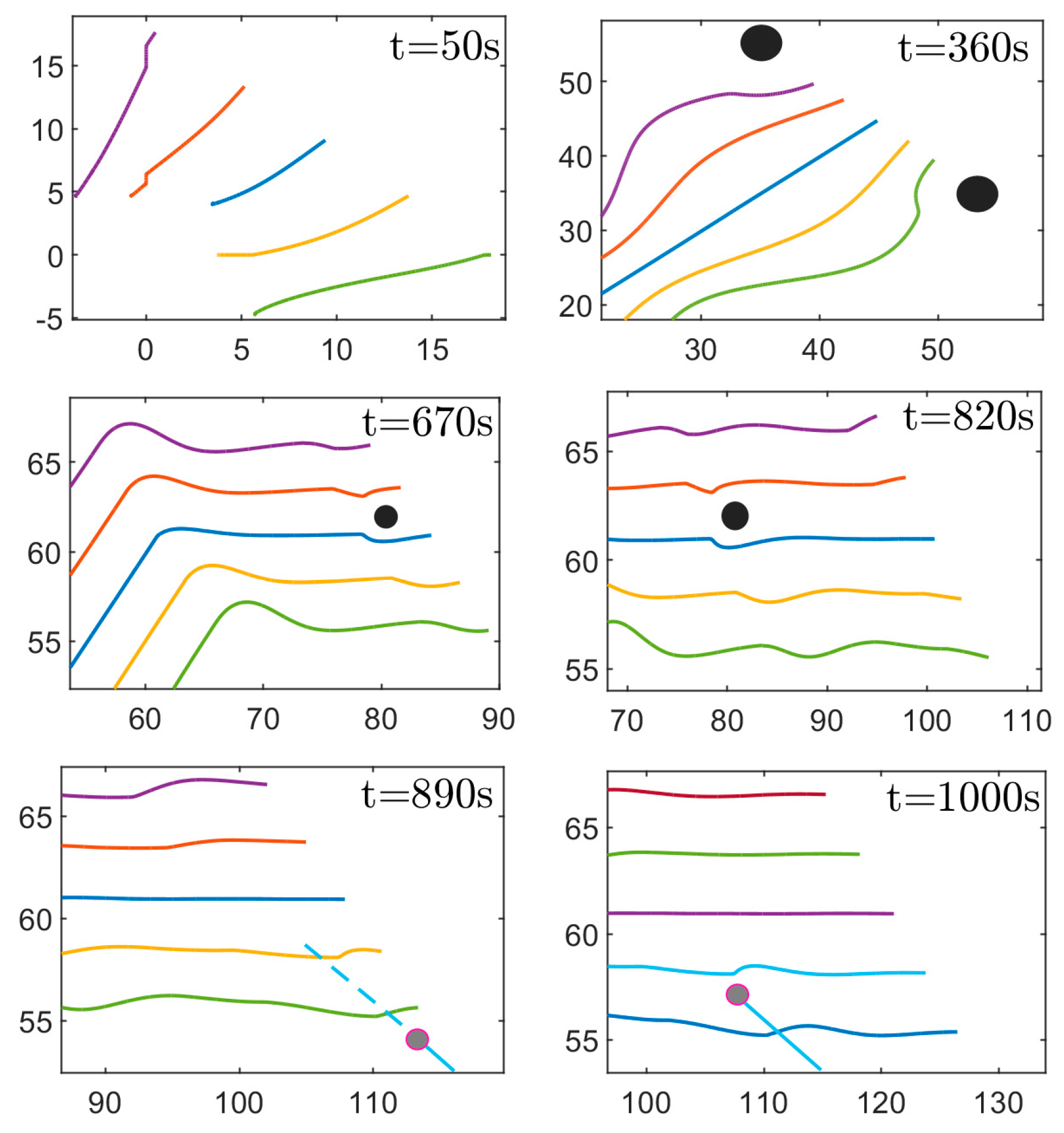
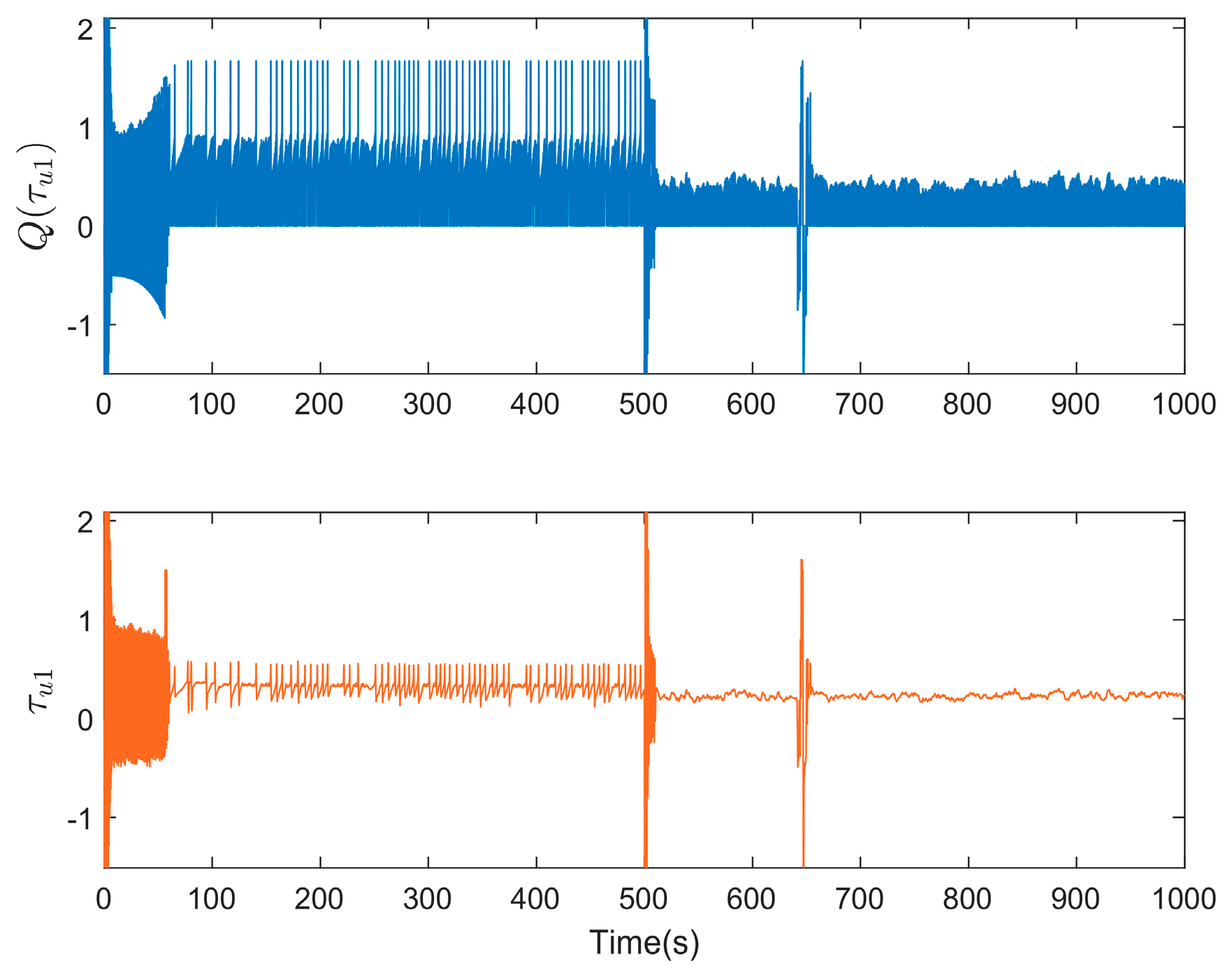
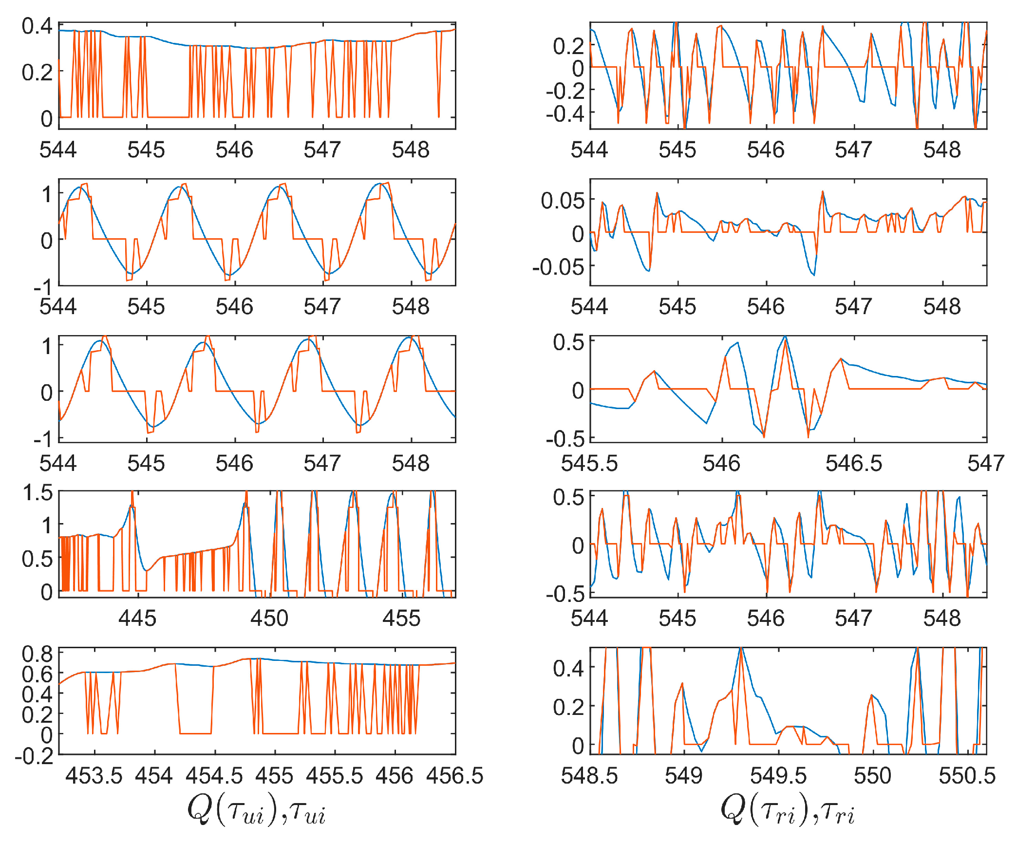
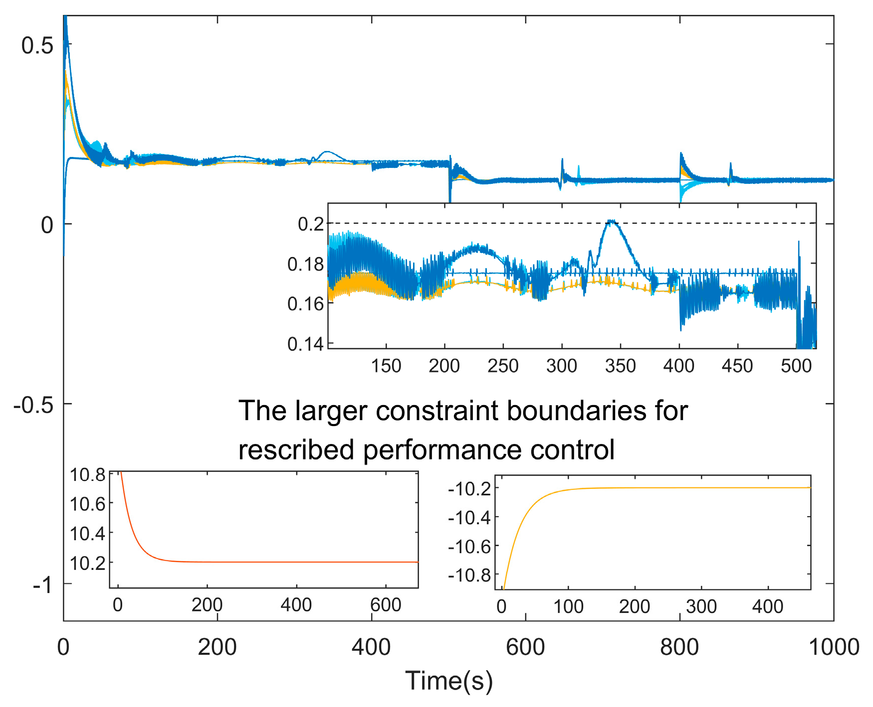
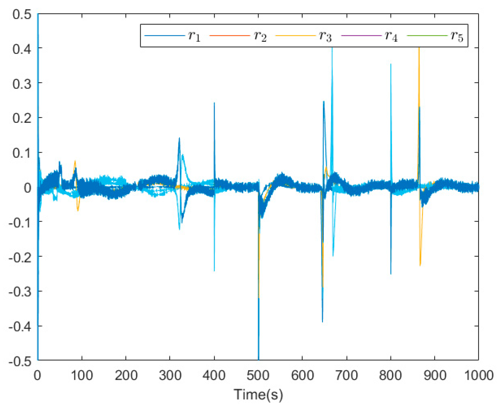
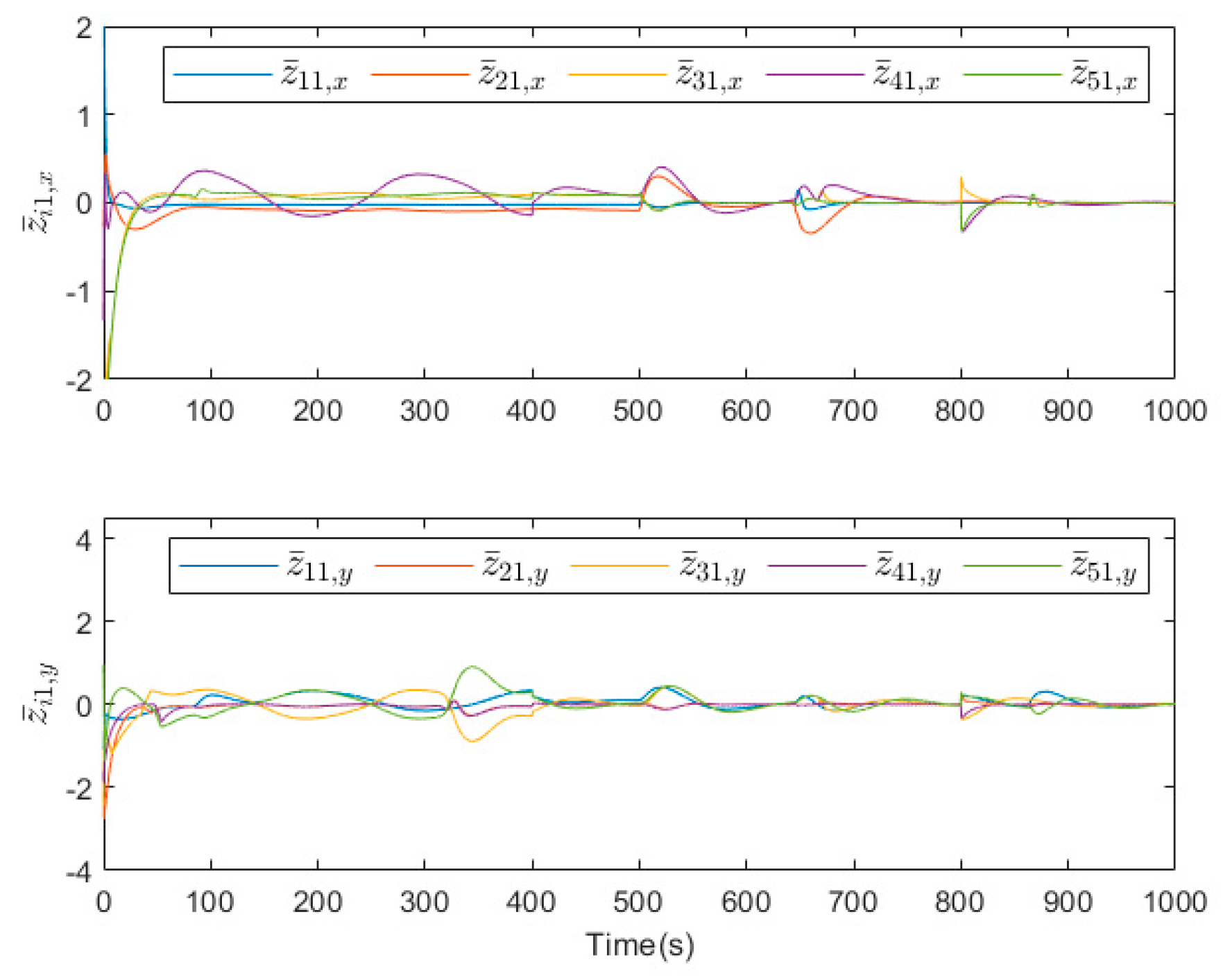
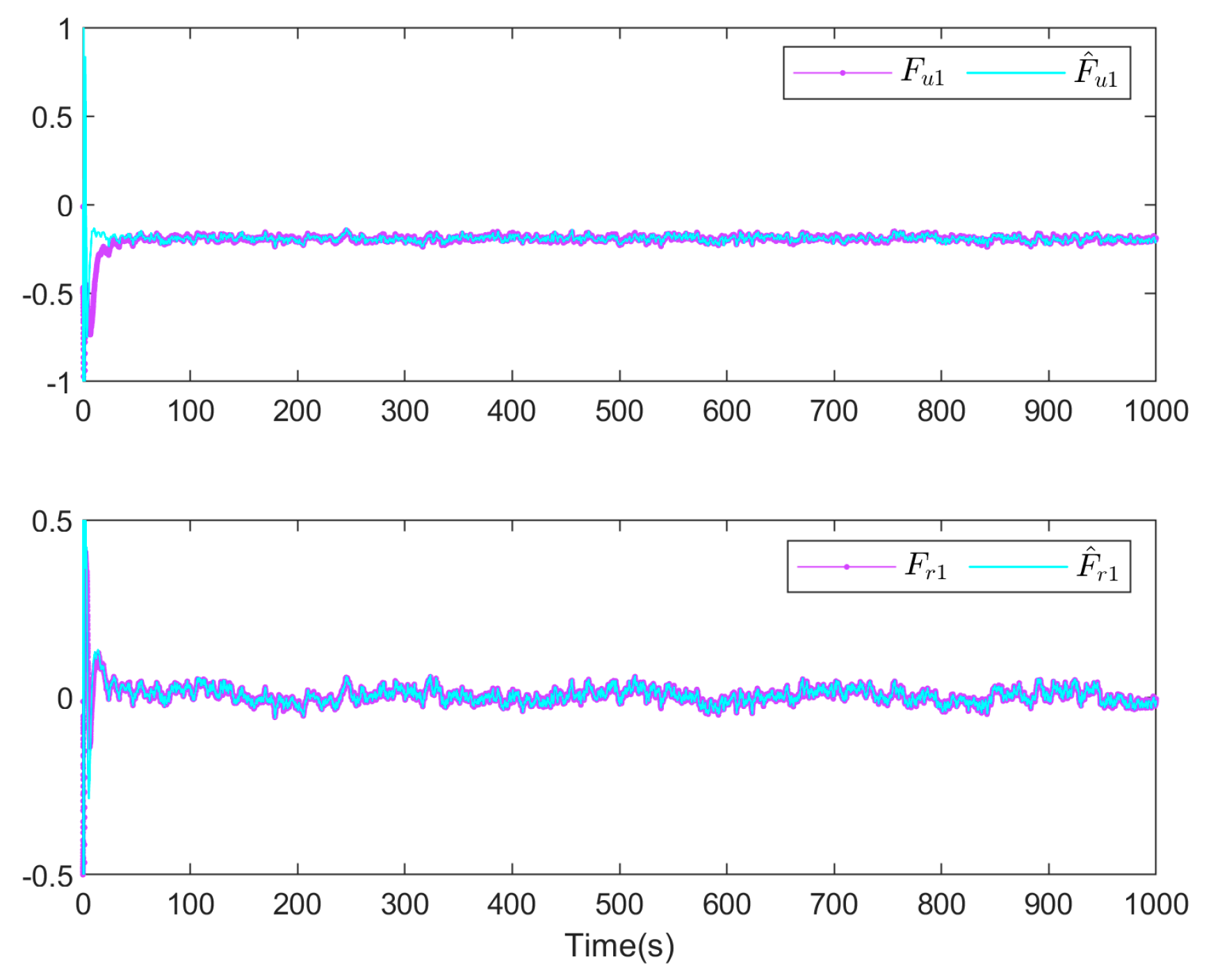
Figure 2, Figure 3, Figure 4, Figure 5, Figure 6, Figure 7, Figure 8, Figure 9, Figure 10, Figure 11 and Figure 12 display the simulation results. Figure 2 depicts that the control scheme designed realizes a time-varying formation pattern consisting of five vehicles guided by a virtual leader providing a parameterized path. Among them, it can be observed that the proposed control scheme can effectively avoid collisions between vehicles and between obstacles. Meanwhile, it can be seen in the dashed boxes a and b in Figure 5 that the motion positions of USV2, USV4, and USV5 in the X or Y direction during the initial formation of the formation do not change with the control signal and are equal to 0 (i.e., exhibiting a dead zone effect). Since the Nussbaum function effectively compensates for the adverse factor caused by the dead zone in the control design process, it enables achieving the desired formation pattern despite the dead zone effect for multi-USV formations. As seen in the dashed box c, USV3 and USV5 effectively avoided obstacles during the time-varying formation pattern. The formation motion trajectory of USV3 could move away from the obstacle, resulting in only a minor deviation from its motion trajectory. As can be seen from the dashed box d, although the dashed trajectory of USV4 and USV5 does not result in a collision with the obstacle, it exceeds the predetermined safe distance between the USVs and the obstacle, thus requiring an obstacle avoidance operation. Unlike in the case of a single obstacle, when two obstacles create a narrow path, the USV formation can effectively cross them. As can be seen in dashed box e, USV1 and USV2 can effectively avoid obstacles when they are present on the parametrized path and do not affect USV1’s tracking of the parametrized path. As can be seen from the dashed box f, unlike the static obstacles considered in the three cases above, not only is USV5 able to avoid dynamic obstacles, but USV3 is able to avoid collisions with USV5 during obstacle avoidance. Figure 3 shows five USVs forming a formation pattern while avoiding collisions and obstacles. Initially, five USVs suffered from a dead zone effect during formation, and then they started forming a predefined formation pattern (i.e., time-varying formation). Then, the USVs reach an environment that contains obstacles with different sizes and positions. The USVs avoid all of the obstacles completely, and finally by passing the obstacles (including dynamic and static obstacles), they form the predefined formation pattern again. The control signals τ u 1 , τ r 1 and quantized signals Q ( τ u 1 ) and Q ( τ r 1 ) are depicted in Figure 4 and Figure 5. It is obvious that the designed control strategy ensures the smoothness and boundedness of the system input. As can be seen from the comparison in Figure 6, there are still control requirements that can be achieved with the accuracy of the quantized signal compared to the control signal. The surge velocities and angular rates of USVs are shown in Figure 7, Figure 8 and Figure 9. Figure 7a shows the surge velocity curves under constrained and obstacle avoidance conditions. It can be seen that the surge velocity u i is well constrained within the predefined constraints. In Figure 7b, the velocity constraint is ignored. It can be seen that during part of the avoidance operation, the surge velocities exceed the constraint boundaries in Figure 7a. As can be seen from the comparison of Figure 7b and Figure 8, Figure 7b shows the unconstrained velocity curves. Based on the results of the prescribed performance technique in Figure 8, there is still a constraint on the velocity even though a sufficiently large constraint boundary is selected. Therefore, it can be shown that the velocity constraint method considered in this paper is able to satisfy both needs with/without velocity constraints. Figure 9 shows the angular rates of USVs, where the large angular rates occur during collision avoidance and formation switching, and then are stabilized. Figure 10 depicts the bounded formation pattern errors of the USVs. It can be seen that larger errors arise as the USV avoids collisions with obstacles and performs formation pattern switching. Subsequently, as the formation pattern errors tend to stabilize, it is able to converge to a small neighborhood around zero. Figure 11 gives the auxiliary Nussbaum parameter ξ i p and the corresponding Nussbaum gain N ( ξ i p ) . It can be seen that the Nussbaum function provides a bounded control gain, which effectively solves the problem of unknown gain parameters arising from the output dead zone. Figure 12 shows the approximation of RBFNN to uncertainty, and it shows that the uncertainties are effectively approximated.
Remark 8.
Note that as collision avoidance and connectivity preservation between USVs are essential in achieving the formation control objectives, we have not ignored collision avoidance and connectivity maintenance, but have compared them only under the no obstacles condition.
Remark 9.
To simulate the effect of dead zones in simulations, a dead zone model is constructed based on parameters  k x i ,   k y i ,   b x i  and  b y i .  It should be noted that unknown gain  k x i  and  k y i , and parameters  b x i  and  b y i  are not used directly in the control process and controller design.
Remark 10.
To adjust these design parameters in the simulation process, the control variable method and trial and error method are usually used, in the order of system parameters > controller parameters > performance parameters > analysis parameters, and according to the trajectory evolution of the tracking error and its maximum/minimum value in the MATLAB 2022a workspace, the feasible range of the design parameters is determined. Finally, appropriate parameters are determined so as to achieve satisfactory control performance.

6. Conclusions

In this article, the distributed cooperative time-varying formation maneuvering control issue has been studied for a fleet of USVs with actuator quantization and the sensor dead zone. A parameterized path has been utilized to achieve the desired formation. To save the restricted communication bandwidth, hysteretic quantization has been utilized. The universal constrained function has been introduced to limit the velocity. By employing RBFNNs in the proposed scheme, the technical difficulty of the unknown nonlinear term has been resolved. Furthermore, a Nussbaum-type function has been introduced to solve the unknown gain issue of the output dead zone. Finally, the simulation results have been presented to demonstrate the validity of the theoretical results.
In the future, we will explore more precise ways to represent the shapes of USVs and obstacles, such as rectangles and triangles. Also, the chattering rejection problem in the control design will be considered, and its impact on the practical application of USVs. In addition, we will explore the application of non-quadratic Lyapunov functions in future work and refer to [53,54] for more in-depth analysis. This will help us to further improve the performance of the system and extend the applicability of the control scheme.

Author Contributions

W.W.: Conceptualization, Writing—original draft, Data curation, Formal analysis. Y.W.: Writing—review & editing. T.L.: Methodology, Formal analysis, Validation, Writing—review & editing, Supervision, Funding acquisition. All authors have read and agreed to the published version of the manuscript.

Funding

This work is supported in part by the National Natural Science Foundation of China (under Grant Nos. 51939001, 61976033, 62173172); The Liaoning Revitalization Talents Program (under Grant No. XLYC1908018).

Institutional Review Board Statement

Not applicable.

Informed Consent Statement

Not applicable.

Data Availability Statement

Data available in a publicly accessible repository.

Conflicts of Interest

The authors declare that they have no known competing financial interests or personal relationships that could have appeared to influence the work reported in this paper. The article includes reprints, photographic reproductions, microfilm, and any other reproductions of a similar nature and translations. The authors are responsible for obtaining from the copyright holder the permission to reproduce any figures for which copyright exists.

Nomenclature

SymbolDescriptionSymbolDescription
USV model ( i = 1 ,   ,   N )
x i x -axis coordinate p i x i , y i T
y i y -axis coordinate D z ( p i ) output of dead zone
ψ i yaw angle f i u
f i v
f i r
Uncertainties including Coriolis,
centripetal, damping force
u i surge velocity
v i sway velocity
r i yaw rate m i u
m i v
m i r
mass and moment of inertia
R i ( ψ i ) rotate matrix
τ i u control inputs
τ i r τ i w u
τ i w v
τ i w r
environmental disturbances
Q ( τ i u ) quantified control inputs
Q ( τ i r )
Virtual leader
θ path variable x 0 d ( θ ) x -axis coordinate
p 0 d ( θ ) parameterized path y 0 d ( θ ) y -axis coordinate
Potential function
l c _ smallest safe radius and collision avoidance detection range J i j c ( p i j ) collision avoidance potential function
l ¯ c
l o _ smallest detection radius and obstacle avoidance detection range J i j o ( p i j ) obstacle avoidance potential function
l ¯ o
l ¯ m maximal and minimal of connectivity range J i j m ( p i j ) connectivity preservation potential function
l m _

References

  1. Burlutskiy, N.; Touahmi, Y.; Lee, B.H. Power efficient formation configuration for centralized leader–follower AUVs control. J. Mar. Sci. Technol. 2012, 17, 315–329. [Google Scholar] [CrossRef]
  2. Sahu, B.K.; Subudhi, B. Flocking control of multiple AUVs based on fuzzy potential functions. IEEE Trans. Fuzzy Syst. 2017, 26, 2539–2551. [Google Scholar] [CrossRef]
  3. Liang, H.; Kang, F.; Hui, C.; Fu, Y. Two-layer virtual leader-following:An adaptive cooperative path following control for crowded uuv swarm subjected to constraints. Ocean Eng. 2022, 257, 111494. [Google Scholar] [CrossRef]
  4. Peng, Z.; Wang, D.; Li, T.; Han, M. Output-feedback cooperative formation maneuvering of autonomous surface vehicles with connectivity preservation and collision avoidance. IEEE Trans. Cybern. 2019, 50, 2527–2535. [Google Scholar] [CrossRef] [PubMed]
  5. Yan, X.; Jiang, D.; Miao, R.; Li, Y. Formation control and obstacle avoidance algorithm of a multi-USV system based on virtual structure and artificial potential field. J. Mar. Sci. Eng. 2021, 9, 161. [Google Scholar] [CrossRef]
  6. Sun, X.; Wang, G.; Fan, Y.; Mu, D.; Qiu, B. A formation autonomous navigation system for usv with distributed control strategy. IEEE Trans. Intell. Transp. Syst. 2020, 22, 2834–2845. [Google Scholar] [CrossRef]
  7. He, S.; Dong, C.; Dai, S.L. Adaptive neural formation control for underactuated unmanned surface vehicles with collision and connectivity constraints. Ocean Eng. 2021, 226, 108834. [Google Scholar] [CrossRef]
  8. Gong, X.; Liu, L.; Peng, Z. Safe-critical formation reconfiguration of multiple unmanned surface vehicles subject to static and dynamic obstacles based on guiding vector fields and fixed-time control barrier functions. Ocean Eng. 2022, 250, 110821. [Google Scholar] [CrossRef]
  9. Yang, Y.; Xiao, Y.; Li, T. A survey of autonomous underwater vehicle formation:Performance, formation control, and communication capability. IEEE Commun. Surv. Tutor. 2021, 23, 815–841. [Google Scholar] [CrossRef]
  10. Xu, Y.; Wu, Z.G.; Pan, Y.J. Observer-based dynamic event-triggered adaptive control of distributed networked systems with application to ground vehicles. IEEE Trans. Ind. Electron. 2022, 70, 4148–4157. [Google Scholar] [CrossRef]
  11. Liu, L.; Wang, D.; Peng, Z.; Han, Q.L. Distributed path following of multiple under-actuated autonomous surface vehicles based on data-driven neural predictors via integral concurrent learning. IEEE Trans. Neural Netw. Learn. Syst. 2021, 32, 5334–5344. [Google Scholar] [CrossRef] [PubMed]
  12. Wang, D.; Kong, M.; Zhang, G.; Liang, X. Adaptive second-order fast terminal sliding-mode formation control for unmanned surface vehicles. J. Mar. Sci. Eng. 2022, 10, 1782. [Google Scholar] [CrossRef]
  13. Sun, Z.; Sun, H.; Li, P.; Zou, J. Formation control of multiple underactuated surface vessels with a disturbance observer. J. Mar. Sci. Eng. 2022, 10, 1016. [Google Scholar] [CrossRef]
  14. Wang, S.; Dai, D.; Wang, D.; Tuo, Y. Nonlinear Extended State Observer-Based Distributed Formation Control of Multiple Vessels with Finite-Time Prescribed Performance. J. Mar. Sci. Eng. 2023, 11, 321. [Google Scholar] [CrossRef]
  15. Liu, L.; Wang, D.; Peng, Z.; Chen, C.P.; Li, T. Bounded neural network control for target tracking of underactuated autonomous surface vehicles in the presence of uncertain target dynamics. IEEE Trans. Neural Netw. Learn. Syst. 2018, 30, 1241–1249. [Google Scholar] [CrossRef] [PubMed]
  16. Cui, R.; Ge, S.S.; How, B.V.E.; Choo, Y.S. Leader–follower formation control of underactuated autonomous underwater vehicles. Ocean Eng. 2010, 37, 1491–1502. [Google Scholar] [CrossRef]
  17. Consolini, L.; Morbidi, F.; Prattichizzo, D.; Tosques, M. Leader–follower formation control of nonholonomic mobile robots with input constraints. Automatica 2008, 44, 1343–1349. [Google Scholar] [CrossRef]
  18. Balch, T.; Arkin, R.C. Behavior-based formation control for multirobot teams. IEEE Trans. Robot. Autom. 1998, 14, 926–939. [Google Scholar] [CrossRef]
  19. Jin, X. Fault tolerant finite-time leader–follower formation control for autonomous surface vessels with los range and angle constraints. Automatica 2016, 68, 228–236. [Google Scholar] [CrossRef]
  20. Hao, L.; Zhang, H.; Li, T.; Lin, B.; Chen, C.P. Fault tolerant control for dynamic positioning of unmanned marine vehicles based on T-S fuzzy model with unknown membership functions. IEEE Trans. Veh. Technol. 2021, 70, 146–157. [Google Scholar] [CrossRef]
  21. Liu, L.; Wang, D.; Peng, Z.; Li, T.; Chen, C.P. Cooperative path following ring-networked under-actuated autonomous surface vehicles:Algorithms and experimental results. IEEE Trans. Cybern. 2018, 50, 1519–1529. [Google Scholar] [CrossRef]
  22. Hua, C.; Zhang, J.; Luo, X.; Pei, W. Position-velocity constrained trajectory tracking control for unmanned underwater vehicle with model uncertainties. Ocean Eng. 2022, 266, 112784. [Google Scholar] [CrossRef]
  23. Jiang, Y.; Peng, Z.; Wang, D.; Chen, C.P. Line-of-sight target enclosing of an underactuated autonomous surface vehicle with experiment results. IEEE Trans. Ind. Inform. 2019, 16, 832–841. [Google Scholar] [CrossRef]
  24. Gu, N.; Wang, D.; Peng, Z.; Liu, L. Distributed containment maneuvering of uncertain under-actuated unmanned surface vehicles guided by multiple virtual leaders with a formation. Ocean. Eng. 2019, 187, 105996. [Google Scholar] [CrossRef]
  25. Cui, R.; Yan, W.; Xu, D. Synchronization of multiple autonomous underwater vehicles without velocity measurements. Sci. China Inf. Sci. 2012, 55, 1693–1703. [Google Scholar] [CrossRef]
  26. Park, B.S.; Yoo, S.J. An error transformation approach for connectivity-preserving and collision-avoiding formation tracking of networked uncertain underactuated surface vessels. IEEE Trans. Cybern. 2018, 49, 2955–2966. [Google Scholar] [CrossRef] [PubMed]
  27. Zhou, Q.; Zhao, S.; Li, H.; Lu, R.; Wu, C. Adaptive neuralnetwork tracking control for robotic manipulators with dead zone. IEEE Trans. Neural Netw. Learn. Syst. 2018, 30, 3611–3620. [Google Scholar] [CrossRef] [PubMed]
  28. Ren, H.; Cheng, Z.; Qin, J.; Lu, R. Deception attacks on event-triggered distributed consensus estimation for nonlinear systems. Automatica 2023, 154, 111100. [Google Scholar] [CrossRef]
  29. Ren, H.; Ma, H.; Li, H.; Wang, Z. Adaptive fixed-time control of nonlinear MASs with actuator faults. IEEE/CAA J. Autom. Sin. 2023, 10, 1252–1262. [Google Scholar] [CrossRef]
  30. Li, Y.; Min, X.; Tong, S. Adaptive fuzzy inverse optimal control for uncertain strict-feedback nonlinear systems. IEEE Trans. Fuzzy Syst. 2020, 28, 2363–2374. [Google Scholar] [CrossRef]
  31. Tong, S.; Sun, K.; Sui, S. Observer-based adaptive fuzzy decentralized optimal control design for strict-feedback nonlinear large-scale systems. IEEE Trans. Fuzzy Syst. 2018, 26, 569–584. [Google Scholar] [CrossRef]
  32. Guo, G.; Zhang, P. Asymptotic stabilization of USVs with actuator dead-zones and yaw constraints based on fixed-time disturbance observer. IEEE Trans. Veh. Technol. 2019, 69, 302–316. [Google Scholar] [CrossRef]
  33. Dong, G.; Cao, L.; Yao, D.; Li, H.; Lu, R. Adaptive attitude control for multi-muav systems with output dead-zone and actuator fault. IEEE/CAA J. Autom. Sin. 2021, 8, 1567–1575. [Google Scholar] [CrossRef]
  34. Hao, L.Y.; Zhang, H.; Guo, G.; Li, H. Quantized sliding mode control of unmanned marine vehicles: Various thruster faults tolerated with a unified model. IEEE Trans. Syst. Man Cybern. Syst. 2019, 51, 2012–2026. [Google Scholar]
  35. Hao, L.Y.; Zhang, H.; Li, H.; Li, T.S. Sliding mode fault-tolerant control for unmanned marine vehicles with signal quantization and time-delay. Ocean Eng. 2020, 215, 107882. [Google Scholar] [CrossRef]
  36. Huang, B.; Zhou, B.; Zhang, S.; Zhu, C. Adaptive prescribed performance tracking control for underactuated autonomous underwater vehicles with input quantization. Ocean Eng. 2021, 221, 108549. [Google Scholar] [CrossRef]
  37. Peng, Z.; Gu, N.; Zhang, Y.; Liu, Y.; Wang, D.; Liu, L. Path-guided time-varying formation control with collision avoidance and connectivity preservation of under-actuated autonomous surface vehicles subject to unknown input gains. Ocean Eng. 2019, 191, 106501. [Google Scholar] [CrossRef]
  38. Lv, G.; Peng, Z.; Wang, H.; Liu, L.; Wang, D.; Li, T. Extendedstate-observer-based distributed model predictive formation control of under-actuated unmanned surface vehicles with collision avoidance. Ocean Eng. 2021, 238, 109587. [Google Scholar] [CrossRef]
  39. Dai, S.; He, S.; Cai, H.; Yang, C. Adaptive leader-follower formation control of underactuated surface vehicles with guaranteed performance. IEEE Trans. Syst. Man Cybern. Syst. 2020, 52, 1997–2008. [Google Scholar] [CrossRef]
  40. He, S.; Wang, M.; Dai, S.L.; Luo, F. Leader–follower formation control of USVs with prescribed performance and collision avoidance. IEEE Trans. Ind. Inform. 2018, 15, 572–581. [Google Scholar] [CrossRef]
  41. He, S.; Dong, C.; Dai, S.L.; Zou, T. Cooperative deterministic learning and formation control for underactuated USVs with prescribed performance. Int. J. Robust Nonlinear Control 2022, 32, 2902–2924. [Google Scholar] [CrossRef]
  42. Lin, J.; Liu, H.; Tian, X. Neural network-based prescribed performance adaptive finite-time formation control of multiple underactuated surface vessels with collision avoidance. J. Frankl. Inst. 2022, 359, 5174–5205. [Google Scholar] [CrossRef]
  43. Chen, G.; Yao, D.; Zhou, Q.; Li, H.; Lu, R. Distributed event-triggered formation control of USVs with prescribed performance. J. Syst. Sci. Complex. 2022, 35, 820–838. [Google Scholar] [CrossRef]
  44. He, S.; Dai, S.; Zhao, Z.; Zhou, T.; Ma, Y. UDE-Based Distributed Formation Control for MSVs With Collision Avoidance and Connectivity Preservation. IEEE Trans. Ind. Inform. 2024, 20, 1476–1487. [Google Scholar] [CrossRef]
  45. Yu, X.; Liu, L. Distributed formation control of nonholonomic vehicles subject to velocity constraints. IEEE Trans. Ind. Electron. 2015, 63, 1289–1298. [Google Scholar] [CrossRef]
  46. Niu, B.; Li, H.; Qin, T.; Karimi, H.R. Adaptive NN dynamic surface controller design for nonlinear pure-feedback switched systems with time-delays and quantized input. IEEE Trans. Syst. Man Cybern. Syst. 2017, 48, 1676–1688. [Google Scholar] [CrossRef]
  47. Cao, Y.; Wen, C.; Song, Y. A unified event-triggered control approach for uncertain pure-feedback systems with or without state constraints. IEEE Trans. Cybern. 2019, 51, 1262–1271. [Google Scholar] [CrossRef] [PubMed]
  48. Cui, G.; Xu, S.; Ma, Q.; Li, Y.; Zhang, Z. Prescribed performance distributed consensus control for nonlinear multi-agent systems with unknown dead-zone input. Int. J. Control 2018, 91, 1053–1065. [Google Scholar] [CrossRef]
  49. Hua, C.; Zhang, L.; Guan, X. Decentralized output feedback adaptive nn tracking control for time-delay stochastic nonlinear systems with prescribed performance. IEEE Trans. Neural Netw. Learn. Syst. 2015, 26, 2749–2759. [Google Scholar] [CrossRef] [PubMed]
  50. Polycarpou, M.M. Stable adaptive neural control scheme for nonlinear systems. IEEE Trans. Autom. Control 1996, 41, 447–451. [Google Scholar] [CrossRef]
  51. Cao, L.; Li, H.; Dong, G.; Lu, R. Event-triggered control for multiagent systems with sensor faults and input saturation. IEEE Trans. Syst. Man Cybern. Syst. 2019, 51, 3855–3866. [Google Scholar] [CrossRef]
  52. Zhang, T.; Xia, M.; Yi, Y. Adaptive neural dynamic surface control of strict-feedback nonlinear systems with full state constraints and unmodeled dynamics. Automatica 2017, 81, 232–239. [Google Scholar] [CrossRef]
  53. Hosseinzadeh, M.; Yazdanpanah, M.J. Performance enhanced model reference adaptive control through switching non-quadratic Lyapunov functions. Syst. Control Lett. 2015, 76, 47–55. [Google Scholar] [CrossRef]
  54. Tao, G. Model reference adaptive control with L1+α tracking. Int. J. Control 1996, 64, 859–870. [Google Scholar] [CrossRef]
Figure 1. Communication graph.
Jmse 12 00848 g001
Figure 2. Trajectories of time-varying formation pattern with collision avoidance and connectivity preservation (Dashed boxes a–f indicate different operations).
Jmse 12 00848 g002
Figure 3. Real-time maneuvering snapshots of the USV formation trajectories.
Jmse 12 00848 g003
Figure 4. Trajectories of control signal τ u 1 and the quantized signal Q ( τ u 1 ) .
Jmse 12 00848 g004
Figure 5. Trajectories of control signal τ r 1 and quantized signal Q ( τ r 1 ) .
Jmse 12 00848 g005
Figure 6. Comparison of quantized signals Q ( τ u i ) and Q ( τ r i ) with control signals τ u i and τ r i . (The blue lines represent quantization signals and the red lines represent control signals).
Jmse 12 00848 g006
Figure 7. Trajectories of surge velocities u i .
Jmse 12 00848 g007
Figure 8. Prescribed performance control with large constraint boundaries.
Jmse 12 00848 g008
Figure 9. Trajectories of angular rates r i .
Jmse 12 00848 g009
Figure 10. Trajectories of formation pattern errors.
Jmse 12 00848 g010
Figure 11. Trajectories of Nussbaum parameters.
Jmse 12 00848 g011
Figure 12. RBFNN approximation to uncertainty.
Jmse 12 00848 g012
Disclaimer/Publisher’s Note: The statements, opinions and data contained in all publications are solely those of the individual author(s) and contributor(s) and not of MDPI and/or the editor(s). MDPI and/or the editor(s) disclaim responsibility for any injury to people or property resulting from any ideas, methods, instructions or products referred to in the content.