
Roadmap for Recommended Guidelines of Leak Detection of Subsea Pipelines


 ,
,  and
and 
Abstract
1. Introduction
- Balancing of pipeline mass or volume input versus output.
- Pressure and/or flow analysis.
- Dynamic models.
- Monitoring of characteristic signals generated by a leak.
- Off-line leak detection.
2. Assessment of Subsea Leak Detection Requirements
3. Key Performance Indicators of Leak Detection System
3.1. System Sensitivity
3.2. Reliability
3.3. Accuracy
3.4. Robustness
3.5. Measured Value Pre-Processing
3.6. Transients
3.7. Criteria for Selecting Leak Detection and Location Technology
- Soil Conditions: Can affect the performance of LDL technology. Tracer gas, for example, migrates faster in dry, porous soil than in moist soil. Acoustic approaches may be influenced by the type of soil surrounding the pipeline. Salt-water areas impacted by tides give unique corrosion challenges for pipelines. Always keep the soil conditions in mind when looking for leak-detecting equipment.
- Water Table: If the pipeline runs below the water table or the high tide level, several LDL procedures will not function. If the pipeline is beneath the water, tracer approaches are less successful because leaking tracer gas may be washed away before reaching a sensor. Alternatively, the tracer could migrate and be detected by a different sensor, suggesting a leak in the incorrect area.
- Pipeline Condition: When choosing leak detection equipment, the age and condition of a pipeline are key factors to consider. To separate a leaking pipeline from a leaky valve, static pressure testing procedures necessitate contemporary, high-quality valves. Pigging may not be possible in older small-diameter pipes with abrupt bends.
- Operations: Routine operations can have an impact on some LDL approaches. Temperature-compensated pressure tests, for example, must be performed while a pipeline is quiet, which may necessitate a brief halt in operations. Heavy traffic in the nearby region can cause acoustic techniques to be disrupted. Facility activities may obstruct pressure point analysis procedures.
- Time Monitoring: Some LDL systems can identify leaks 24 h a day, seven days a week (continuous monitoring). Other techniques provide a snapshot, or assessment, of the pipeline’s current state. To implement a successful leak control program, regulators may demand that a snapshot technique be used at specific time intervals.
- Spatial Resolution: Different levels of spatial resolution are provided by leak detection and locating systems. Pigging, cables, and acoustic techniques, when used correctly, can precisely find leaks. The accuracy of tracer leak localization, on the other hand, is a function of the spacing between sample points, whereas static pressure testing approaches do not detect leaks at all. Identifying a leak with one approach, such as pressure testing, and then locating it with another technique, such as tracers, is sometimes the best way to tackle leak detection difficulties.
- Volumetric Measurement of Leak Rate: This leak detection technique offers a volumetric measure of the hydrocarbon leak rate. An example of this technique is temperature-compensated pressure testing. There are additional methods, such as product-sensitive cables. These additional methods indicate where the hydrocarbon has been identified but not how much is there.
- Ease of Retrofit: Most piping systems have been in use for a long time. As a result, it is critical to consider whether LDL technology can be implemented into an existing pipeline. Some procedures, such as temperature-compensated pressure testing, can be used on most pipelines, new or old, with little difficulty. The hardware required for these approaches is not built into the pipeline system and can be brought in by the contractor doing the test. These systems, on the other hand, can be integrated into the system if it is proven to be cost-effective.
4. Leak Detection Methods and Current Industry Practice
4.1. External Leak Detection Systems
- Active Acoustic Leak Detection: This technique uses sonar detectors that send out sound pulses, which pass through water and reflect upon contact with mediums such as gas or oil. The sound pulse deflects and returns to the sensor if the acoustic impedance of the medium (or leaking fluid) is different from that of water. The most used sensors are ROV deployable. It should be noted that using acoustic transmitters and receivers is common on a liquid pipeline. The acoustic transmitters and receivers are installed on a liquid pipeline at specific distances. The correlation between the signals transmitted and received is calculated to determine if a leak exists and its possible location. This method is since the acoustic properties will be changed due to the presence of an opening in the pipeline. The distance between the transmitter and receiver is very short, usually a few hundred meters only. This leak detection system is highly sensitive to gas due to its impedance contrast with water, hence, a gas leak in water can be easily detected. Also, high gas rates and background noise can produce false leak detection.
- Passive Acoustic Leak Detection: This method uses acoustic sensors that are either clamped onto the pipeline or deployed using an ROV. The clamp-on sensors are usually pre-installed on the pipeline at critical points such as joints, valves, flanges etc. or mounted on subsea structures such as manifolds, subsea trees, PTS etc., while the deployable sensors are brought in as part of the pipeline inspection service. The sensors detect the high-frequency sound produced by the leak and transmit signals via cable to the subsea control system (in the case of clamp-on sensors) or a receiver onboard the ROV (in the case of deployable sensors). This system detects leak rates as low as 0.1 L/min; Produces uninterrupted while monitoring for leakage; and Sensors are not affected by current, turbidity or visibility. High gas rates and background noise can mask the high-frequency sound of leaks; Deployable sensors cannot be used for continuous pipeline monitoring.
- Capacitance: The capacitance method involves the use of sensors that can detect and measure changes in an electric property called capacitance in the medium surrounding the sensors. The capacitance varies for different fluids such as water, gas and oil and gives specific values for each of these fluids. In the event of a gas leak into the surrounding water, the sensors will indicate a change in the capacitance value. The sensors can be placed onto subsea structures or critical points on the pipeline such as valves, joints, flanges etc. This system provides high sensitivity when in contact with the leaking medium. It also needs to be in direct contact with the leaking fluid to detect it; the leaking medium can be affected by the surrounding current and move away from the sensor, therefore, a “hat” arrangement next to the sensor may be needed to capture the leaking hydrocarbons; and Positioning of the leak is difficult since the leak could have reached the sensor through drifting currents.
- Fluorometry: Subsea pipeline leaks can be detected by inserting dyes into the hydrocarbon stream and the use of ROV-deployed sensors that use “special” light sources to detect the dyes that come out from the location of a leak. The system provides uninterrupted production during leakage inspection. It is also limited to a detection range of up to 10 m; cannot be used for continuous pipeline monitoring; requires ROV and so poor tidal conditions can make it difficult for ROV operations.
- Fiber Optics: This technology uses a continuous optic fiber cable that runs parallel to the main hydrocarbon pipeline to help detect leaks along the pipeline. The fibers are noise-sensitive and can detect high-frequency noises created by leaks enabling them to locate the position of the leak along the pipeline. The optic fiber, depending on its type, can also detect leaks by comparing the temperature deviation of the surrounding environment against field-verified data. However, this type is considered less suitable for subsea applications since the accuracy of this method will vary with ambient current conditions [22,23]. This system detects leakage rates as low as 0.01 L/min; Identifies the location of the leak within the 1.0 m range; early detection of leaks can help reduce adverse environmental impacts; continuous pipeline monitoring without production interruption; and can be installed on buried pipeline section. It also represents expensive technology and therefore high CAPEX (Capital Expenditures).
4.2. Internal Software-Based Leak Detection Systems
- Pressure (only) Monitoring: This is the simplest technique for leak detection. The pressure is monitored at the inlet and outlet of the pipeline using pressure transmitters and a rate of change of pressure beyond the expected threshold during a steady-state operation indicates a leak in the system. This system does not require any additional instrumentation, hence overall system reliability is not affected; and early detection of large leaks is possible, as it is immediately reflected in the system outlet pressure. It also detects only large leaks; and cannot determine the size of the leak; the accuracy of measurement is heavily reliant on the accuracy of the pressure transmitter; and is not ideal for transient operations and multiphase flow due to large pressure fluctuations. In other words, if the acoustic pressure waves and real-time transient techniques are used for leak location in the leak detection system, the pressure transmitters should be fast-acting in the order of 0.1 s including any time delay for the diaphragm seals. The time stamping of the Integrated Control and Safety Systems (ICSS) controller shall be 0.1 s or faster or the location error will increase. Operators must differentiate between deliberate changes in operating conditions and leaks. The pressure monitoring cannot estimate the leak location. Pressure monitoring is not very good at detecting small leaks, especially in long pipelines that produce only a slow variation in pressure or flow. The pressure monitoring cannot detect steady-state leaks.
- Mass or Volume Balance: This method typically checks the mass balance over various time windows to detect large, medium, and small leaks, respectively. The method may use pressure and temperature measurements to compensate for inventory changes. The main drawback of this method is that long averaging times are needed to indicate leaks without generating false alarms. This technique involves monitoring the fluid flow rate at the inlet and outlet of the pipeline and a leak is evident when the mass rate exiting the pipeline is lower than that at the inlet. The flow rate is measured using flowmeters at either end of the pipeline and the data are transmitted to the Integrated Control and Safety System (ICSS) system on the platform or the onshore plant. This system relies on existing instrumentation such as flowmeters and PT transmitters, therefore, additional instrumentation is not required, and relatively cheaper technology. It also works well only for steady-state operations; the accuracy of measurements is heavily reliant on the accuracy of flowmeters and leaks could be undetected if the quantity of the leak is smaller than the measurement error (i.e., 1% error in the flowmeter measurement will not be able to detect a leak smaller than 1% of the total flow when producing at steady state); and requires sufficient measuring instruments both subsea and topsides to accurately track transient conditions. The minimum requirements for the overall performance of a multiphase flowmeter with respect to accuracy and repeatability of measured/computed flow rates of individual components shall be as below or better:
- Uncertainty: Liquid flow rate +/−10%, Gas flow rate +/−10%, Water cut +/−10%.
- Repeatability: Oil flow rate +/−2%, Water flow rate +/−2%, Gas flow rate +/−2%.
- Real-Time Transient Modeling: The real-time transient modelling (RTTM) method uses a dynamic software model to track the transient conditions (mainly pressure and flow rate) of the subsea pipeline. The derivation of the principal equations of fluid dynamics for the dynamical behavior of a fluid is determined by the following conservation laws, namely [29]:
- Conservation of mass.
- Conservation of momentum.
- Conservation of energy.
- Equation of state for the fluid.
The above conservation laws can be collected into one system of equations (i.e., conservation of momentum and conservation of energy are not independent) to a better overview of the various terms involved. For instance, a flow field is characterized by balance in mass, momentum, and total energy described by the continuity equation, the Navier-Stokes and Euler equations. The model is tuned with numerous simulated operation scenarios and compares the real-time measured flow conditions against the predicted values for any particular operation. A mismatch between the measured and predicted values indicates a leak in the system. This technique is an advancement of the mass balance method. The dynamic model method uses equations of state to mathematically emulate the fluid flow within the pipeline. The deviation between modelled variables and measured pipeline variables is theoretically indicative of a leak condition. This method, however, has historically proved difficult to successfully implement for online applications. This is due to the complexity of the modelling variables and calculations required. Typically, problems with tuning and high false alarm rates have prevented the successful implementation of a reliable system of this type. The system spans a wide range of applications apart from leak detection, such as hydrate formation risk analysis, pig tracking, slug tracking, pipeline blockage, corrosion rate, etc. It also provides a leak detection rate that varies widely from 1% to 10% of the maximum production throughout depending on:- Trained personnel required to use and maintain the RTTM software.
- Instrumentation accuracy.
- Accuracy of detecting leak rates, which vary depending on the accuracy of flowmeters and PT transmitters.
- The complexity of the system, which:
- -
- May not detect very small leaks such as that capable with hardware-based LDS.
- -
- May not accurately identify the location of the leak.
- -
- May require extensive additional instrumentation for real-time data tracking.
- -
- The system is based on driven data that are completely dependent on qualitative and quantitative data available from the pipeline systems.
- -
- RTTM system makes it difficult to anticipate all possible operating scenarios that might occur during pipeline operations.
- Statistical Pipeline Leak Detection System (SPLD): Dynamic models have proved to be of high initial cost with a high cost of ownership and no great improvement of sensitivity over that of the Statistical Pipeline Leak Detection (SPLD) system. In other words, SPLD requires a high initial cost and is additionally difficult to implement for online applications. This is because the calculation and modelling required are quite complex and this approach is not reliable for implementation due to the high false alarm rate [30]. SPLD applies a mass balance principle; over a small interval of time, the difference between the mass entering and the mass leaving the pipeline should be equal to the change in the inventory. The mass flows in and out of the pipeline are obtained from the flow meter readings and the inventory changes are estimated from the pressure measurements at the ends of the pipeline. At each sample time, t, a mass imbalance, τ(t), is calculated. In general, τ(t) is non-zero due to instrument errors. Over a while when there are no leak alarms, the mean (m) and variance (σ2) of τ(t) are calculated. Then, at each sample time, the latest series of values of the mass imbalance {τ(1), τ(2), …, τ(t)} is subjected to analysis to determine whether or not the fluctuations are statistically significant. The leak-free hypothesis H0 is that τ(t) is Gaussian with mean m and variance σ2. The leak-present hypothesis H1 is that τ(t) is Gaussian with a mean (m + Δm) and variance σ2. By repeating the statistical significance tests for different values of Δm, checks can be made for the presence or absence of leaks of different sizes. The rules applied for decision-making are developed to give desired values of the false alarm probability and the missed alarm probability. At any sample time, the current decision will be to accept hypothesis H0 (no leak), to accept hypothesis H1 (leak), or to accept neither of these hypotheses. SPLD is tuned to interpret a non-zero mass imbalance as an instrument error. A small leak that is growing with time (e.g., a corrosion pinhole) could therefore be misinterpreted as increasing instrument drift. After a leak is detected, its location can be estimated using the SPLD. The SPLD is claimed to be able to detect leaks of 0.5–2% of the design flow rate and to locate them with a typical accuracy of ±15% of the pipeline length [24]. The accuracy of location could be worse than this for small leaks that are only just detectable or for very large leaks that upset the pipeline dynamics. The performance of the SPLD will be judged mainly on the following system attributes:
- Accuracy of detecting leaks of different sizes.
- False alarm rate.
- Missed alarm rate.
Lesser factors to be considered in selecting a system would be:- Capital cost.
- Operating cost.
- Reliability, availability, and maintainability under conditions of continuous use.
- Level of technical expertise required to maintain the system.
4.3. Off-Line Leak Detection Methods
- Aerial/Ground Line Patrol: The subsea pipelines can be visually inspected for leaks during regular inspection services throughout production life. This is conducted with the help of an aircraft or boat, which goes along the pipeline route inspecting for bubbles on the surface of the sea. If supply vessels travel along the trunkline route, this will allow regular inspection. This method can detect only large leaks of gas, but condensate leaks will be visible.
- Static Pressure Test: It is well known that the pressure in a pressurized pipeline drops if there is a leak in a pipeline. Every pipeline normally undergoes a hydrostatic pressure test to prove the strength of the pipeline materials following construction and before operation. The hydrostatic test pressure and test segments of the pipeline are usually selected to achieve certain stress within the pipe walls during the hydrostatic test that is close to, but not exceeding the specified minimum yield strength of the pipe material as defined by the design code. The test media is usually water, although in some limited cases (e.g., dedicated aviation facilities with no facility for flushing/drying), the product itself might be used as the test media. As a condition of the regulatory process, many liquid pipelines are required to be pressure tested regularly. This may be annually, bi-annually, or at some other specified interval. This pressure test would normally be undertaken with the conveyed fluid, under static conditions at a pressure typically around 110% of the maximum allowable operating pressure. Most pipelines are not subjected to periodic in-service pressure tests. The use of the static pressure test can assist in identifying the location of the leak easily. However, the use of the static pressure test can result in enlarging an existing defect and activating it to grow. During the pressure test, a biodegradable tracer dye may be injected to provide visual evidence of a leak to aid leak location. The environmental impact of such dyes shall be assessed and confirmed as acceptable before use.
- Shutdown and Monitor Pressure Decay: This method is simpler than the previous method and simply monitors for pressure loss in the pipeline once the pipeline is shut at both ends. The pipeline is not pressurized but is generally at the normal operating pressure before a shut-in.
- Pipeline Survey by ROV: A survey of trunkline, flowline, and subsea structures by ROV will be carried out regularly and will detect leaks.
- RADAR Detection: This technique can be used for the detection of oil or condensate on the surface of the sea.
- Satellite Detection: Detection of oil on the surface of the sea can be performed from satellites.
- Acoustic Techniques: The “acoustic pressure waves” or “real-time transient” model technologies can be included in the LDS. Acoustic pressure waves give a quick result but can miss the initial pressure spike that is generated when the leak first occurs (i.e., the spike pressures generated when the liquid flow is suddenly stopped). It requires fast-acting pressure transmitters and a fast scan time on the applicable Integrated control and safety system nodes. To overcome propagation delays, the recommended practice would be to trap the detection “event” within the local controller, exploiting its fast-scanning capability. Each event, together with its accurate time stamp, would then be transmitted to the master leak detection system for analysis. Real-time transient models take longer to determine the leak location and may not reach an accurate conclusion before block valves are closed. If the leak location is of prime importance, both acoustic pressure wave and real-time transient models shall be employed.
- Leak Detection by Dye Injection: If the leak is so large that the pipeline has flooded and the gas emission has stopped before the leak has been located, then it is possible in principle to pump inhibited seawater and dye into the pipeline. During pumping, an ROV fitted with a color camera, ultraviolet light, flow meter, and hydrophone can fly along the pipeline to locate the leak.
- Intelligent Pigging: Leak detection may in principle be carried out with the use of pigs, though only if the line is still piggable. The commonly used pigging methods include:
- Acoustic Pig: This is used in liquid-filled pipelines. Tracked by a surface vessel, the pig is inserted into the pig launcher end and driven down the pipeline. If the isolation valve on the receiver end is closed then the only route of escape for the fluid in the pipeline is through the leak. When the pig reaches the source of the leakage, the liquid ahead of it is incompressible and stops. A diver or ROV may then locate the pig within the pipeline accurately with an acoustic tracker.
- Hydrophone Pig: A hydrophone pig contains a data storage and tracking unit. The sound of escaping fluid at the leak is picked up by the hydrophone and stored electronically together with the instrument running time. After the arrival of the pig at the receiver end, a plot of the noise level or frequency versus the real-time can be obtained. This plot shows the time at which a leak was located. The location of the leak is determined from the accurate record of fluid flow. Alternatively, the pig may be fitted with an acoustic pinger and tracked as it travels down the pipeline by a surface vessel to produce a plot of the pig’s position in real-time.
- Barrier Pig: This is designed to provide a high-pressure temporary blockage that can be set at any desired location in the pipeline. Leak detection is carried out by hydrostatic pressurization of the pipeline section between the pump and the barrier pig (which would be a major operation for a long pipeline). If no pressure drop occurs, the pig is pumped further along the pipeline and set. Pressurization and checks for leaks are carried out again. This process is repeated until the pig has moved past the leak; at which time the pressure drop will indicate the presence of the leak. The approximate location of the leak is, therefore, between the latest and the previous pig position.
- Constraints on Use of Leak Detection Pigs: This includes the following:
- The risk that the inspection pig (or any preceding gauging pig) may become jammed at the damaged section of the pipeline or on hydrates in deepwater sections of the pipeline.
- The difficulty of controlling a pig in a gas pipeline with great changes of elevation unless an adequate backpressure exists in the pipeline.
- The availability of suitable pigs.
4.4. Survey, Inspection, and Damage Investigation
- Helicopter or fixed-wing aircraft.
- Towed fish.
- Remote-operated towed vehicle (ROTV).
- Autonomous underwater vehicle (AUV).
- ROV/diver.
- Pigging.
- Fixed-wing Aircraft and Helicopters: Due to their speed and long range, fixed-wing aircraft are the preferred means of confirming the location of a leak and for making estimates of the bubble plume diameter, from which the leak rate and size may be inferred. Helicopters could also be used but have limited flight time due to refueling needs. The average round trip for a helicopter is only about 260 miles so for example, the whole gas export pipeline could not be covered by a single helicopter flight. However, the emergency controller may check the availability of helicopters in the field and may use them if it seems that they might have adequate capabilities for the task at hand. Fixed or rotary-wing aircraft envisaged for use in a leak detection operation should be provided with the pipeline route coordinates as a series of waypoints for navigation. Where an aerial detection of a suspected leak has failed, or where the size of the leak is believed to fall below that suitable for aircraft search and detection, then underwater search techniques must be considered.
- Towed Fish: Towed fish deployed sensors can be mobilized onto standard-sized survey vessels (50–60 m length), supply vessels or other vessels of opportunity, dependent on availability and urgency. The use of towed fish allows a faster rate of pipeline search than an ROV inspection/search and can be conducted without the need for a dynamically positioned support vessel. Tow speeds of up to 6 knots may be achieved, enabling up to 200 km of pipeline to be covered in 24 h.
- Remotely Operated Towed Vehicles: Remotely operated towed vehicles (ROTV) comprise a box-kite construction tow vehicle, with maneuverability achieved via vertical and horizontal flaps on the leading edge of the vehicle, controlled by pilot joystick operation, with any gross position changes being made in conjunction with vessel helm action. The detection of any leak would be enhanced by the ability to control with precision the sensor platform for the pipeline. The use of ROTV deployment combined with Ultra-Short Baseline (USBL) acoustic positioning would enable this level of confidence to be obtained at relatively high speeds of line-kilometer coverage. If the ROTV was fitted with side-scan sonar, then the fish could be maintained at the correct offset to the pipeline, irrespective of USBL quality, sufficient to allow the search to continue.
- Autonomous Underwater Vehicle: The development of autonomous underwater vehicles (AUV) in recent years, if the potential can be fully realized, should lead to survey and inspection applications which would obviate the need for tethered ROV and DP support vessels. The AUV concept involves a mobile, self-propelled instrumentation platform fitted with actuators, sensors, and onboard intelligence designed to complete tasks autonomously. The navigation for an AUV mission entails the vehicle following a pre-programmed route, using a combination of positioning techniques, appropriate to the task. It is conceivable that an AUV could be stationed at the offshore platform from where it could be deployed for both structure and pipeline inspection, being fitted with acoustic, visual, CP, NDT, and leak detection sensors. Given the known coordinates of the pipeline and the associated terrain model, the AUV would navigate using Doppler velocity-aided DGPS in conjunction with terrain-following techniques and/or pre-installed acoustic reference beacons. This is the case for at least for the early stages of the Malampaya field life; however, it is unlikely that such technology would represent a viable leak location tool [17].
- ROV/Diver Operations: The mobilization of a diving support vessel for diver range survey and investigation would normally include a Remote-Operated Vehicle (ROV) spread for the initial search. The use of ROV can be severely limited by low visibility and high seabed currents. Operational limitations need to be balanced against the inspection data required. Once the leak or damage has been located, a full diver/ROV survey may need to be carried out to detail the actual leak or damage. The type and size of the ROV would be dictated by the actual location of the leak (water depth, current regimeb etc.). The positioning of the leak by other methods is considered a cost-effective solution before the mobilization of an ROV of size and power sufficient to cover the complete range of depth and current scenarios that exist on the pipeline routes.
- Leak Detection by Pigging: Leak detection may in principle be carried out with the use of pigs, though only if the line is still piggable. The risk is that the inspection pig (or any preceding gauging pig) may become jammed at the damaged section of the pipeline or on hydrates in deepwater sections of the pipeline. The difficulty of controlling a pig in a gas pipeline may lead to great changes in elevation unless an adequate backpressure exists in the pipeline. In addition, it is considered that less complex methods (namely PIMS and visual observation) are available for leak detection for the gas export pipeline. Pigging methods include:
- Acoustic Pig: This is used in liquid-filled pipelines. Tracked by a surface vessel, the pig is inserted into the pig launcher end and driven down the pipeline. If the isolation valve on the receiver end is closed then the only route of escape for the fluid in the pipeline is through the leak. When the pig reaches the source of the leakage, the liquid ahead of it being incompressible will stop. A diver or ROV may then locate the pig within the pipeline accurately with an acoustic tracker [35,36].
- Hydrophone Pig: A hydrophone pig contains data storage and a tracking unit. The sound of escaping fluid at the leak is picked up by the hydrophone and stored electronically together with the instrument running time. After the arrival of the pig at the receiver end, a plot of the noise level or frequency versus the real-time can be obtained. This plot shows the time at which a leak was located. The location of the leak is determined from an accurate record of fluid flow. Alternatively, the pig may be fitted with an acoustic pinger and tracked as it travels down the pipeline by a surface vessel to produce a plot of the pig’s position in real-time.
- Barrier Pig: A barrier pig is designed to provide a high-pressure temporary blockage that can be set at any desired location in the pipeline. Leak detection is carried out by hydrostatic pressurization of the pipeline section between the pump and the barrier pig (which would be a major operation for a long pipeline). If no pressure drop occurs, the pig is pumped further along the pipeline and set. Pressurization and checks for leaks are carried out again. This process is repeated until the pig has moved to pass the leak, at which time the pressure drop will indicate the presence of the leak. The approximate location of the leak is, therefore, between the latest and the previous pig position. Constraints to the use of leak detection pigs include:
- Photography: Underwater photographs of 35 mm of the damage will be more useful than videotape alone, because of the higher resolution. These photographs should be taken with an underwater scale in each shot. Video can be used to provide supplementary information. This technique applies only to gas leaks.
- Impressions and Castings: Castings and impressions of dents, gouges, scratches, and cracks can be made by diver or ROV, although accessibility in some locations will deny ROV access.
- Measurement: This includes the taut wire measurement of deflections; scale measurement from datum points; and straight edge measurements of dents and deflections.
- NDT Methods: Divers or an ROV can perform non-destructive testing techniques, subject to limits on access by ROV, including:
- -
- Ultrasonic A scan UT with angle probe, or radiography with localized gamma source, for surface and sub-surface crack detection.
- -
- Magnetic particle inspection, or eddy current technique, for surface defect detection.
- Engineering Assessment: An engineering assessment of the pipeline damage, together with the relevant as-built data and previous inspection data, is required to determine whether a repair is required. The aim here should be to avoid overreaction and unnecessary repairs. If a repair is required, the important factor will be to plan the repair to minimize production downtime. The repair costs themselves will be a secondary consideration.
4.5. Damage/Leak Classification and Reporting
- Water depth and Transverse Mercator (PTM) coordinate the damage.
- Damage assessment.
- The number of the nearest field joint.
- Distance of the damage from the nearest field joint.
- Details of the seabed conditions.
- Burial status of the pipeline.
- Concrete coating.
- Debris in the surrounding area.
- Clock position of the longitudinal seam weld.
- Whether the pipeline remains piggable.
4.6. Machine Learning and Data Acquisitions
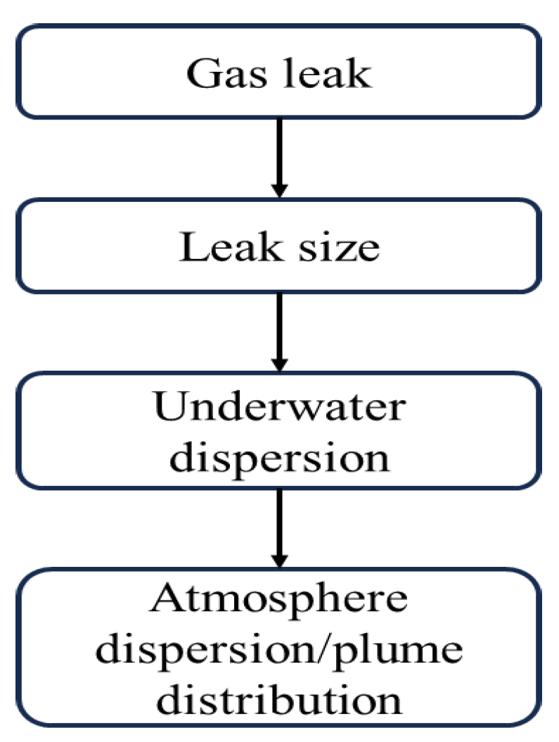
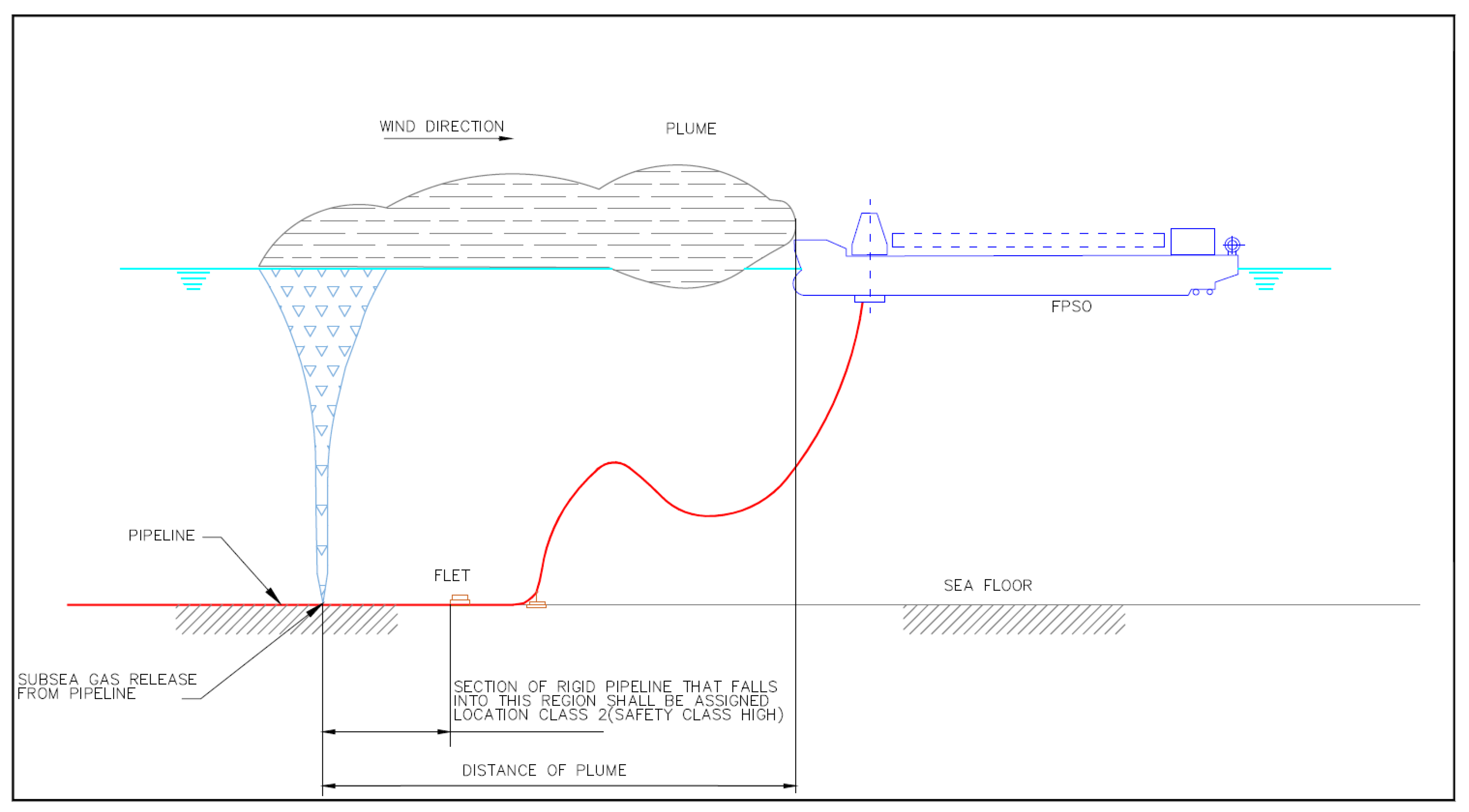
4.7. Underwater Gas Release and Dispersion from Subsea Gas Pipeline Leak
- Although, this section and subsections focus only on a gas pipeline leak. In the case of a multiphase (i.e., gas, oil, and water) pipeline leak, the time needed by the oil to reach the surface is longer than the gas. Consequently, a higher spread occurs for the oil and oil slick dimensions are higher than the bubbling area (for the gas). For the multiphase pipeline, the analysis of the vaporization process following the pool/slick formation during the leakage transients should be conducted; this is to determine the following:
- The source term definition for the Pool Fire impact evaluation in case an immediate ignition occurs.
- The potential contribution to the Flash Fire impact evaluation in case of delayed ignition.
4.7.1. Hazard Description
- External impact from the following sources:
- -
- objects dropped from the offshore facility.
- -
- objects dropped from the mobile offshore drilling unit (MODU).
- -
- shipping including anchor, anchor chain impact and dragged anchors.
- -
- future construction.
- -
- inspection, monitoring or maintenance, and repair (IMR) campaigns.
- Corrosion (internal and external).
- Natural hazards.
- Structural damages.
4.7.2. Leak Size
- Minimum detectable leak size.
- Effect of pipeline pressures and flow rates.
- Bubble plume diameter.
- Flame height for ignited bubble plume.
- Sufficiently small leak size that can be regarded as non-hazardous.
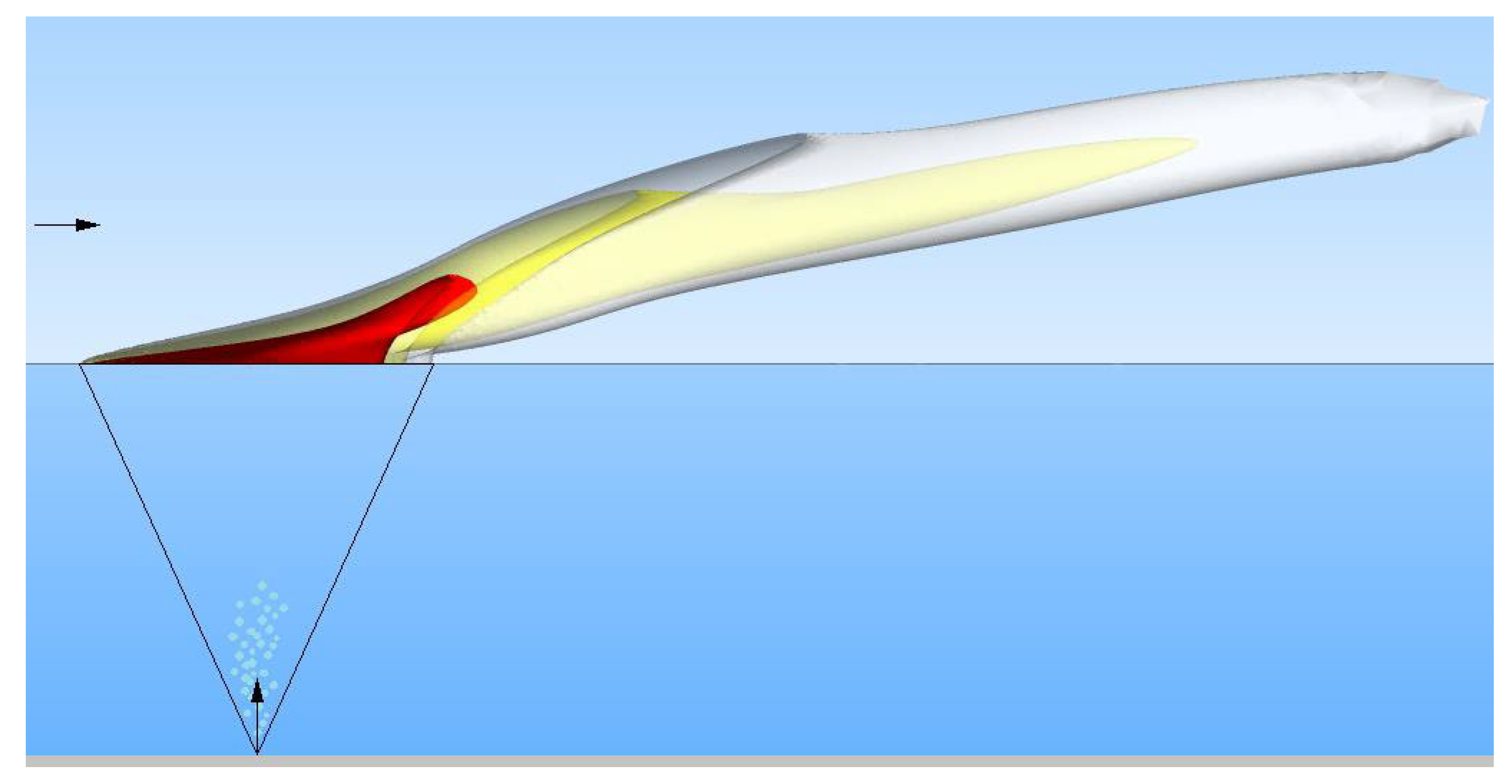
4.7.3. Underwater Dispersion
- Flow Establishment (ZOFE).
- Established Flow (ZOEF)
- Surface Flow (ZOFS).
4.7.4. Atmosphere Dispersion
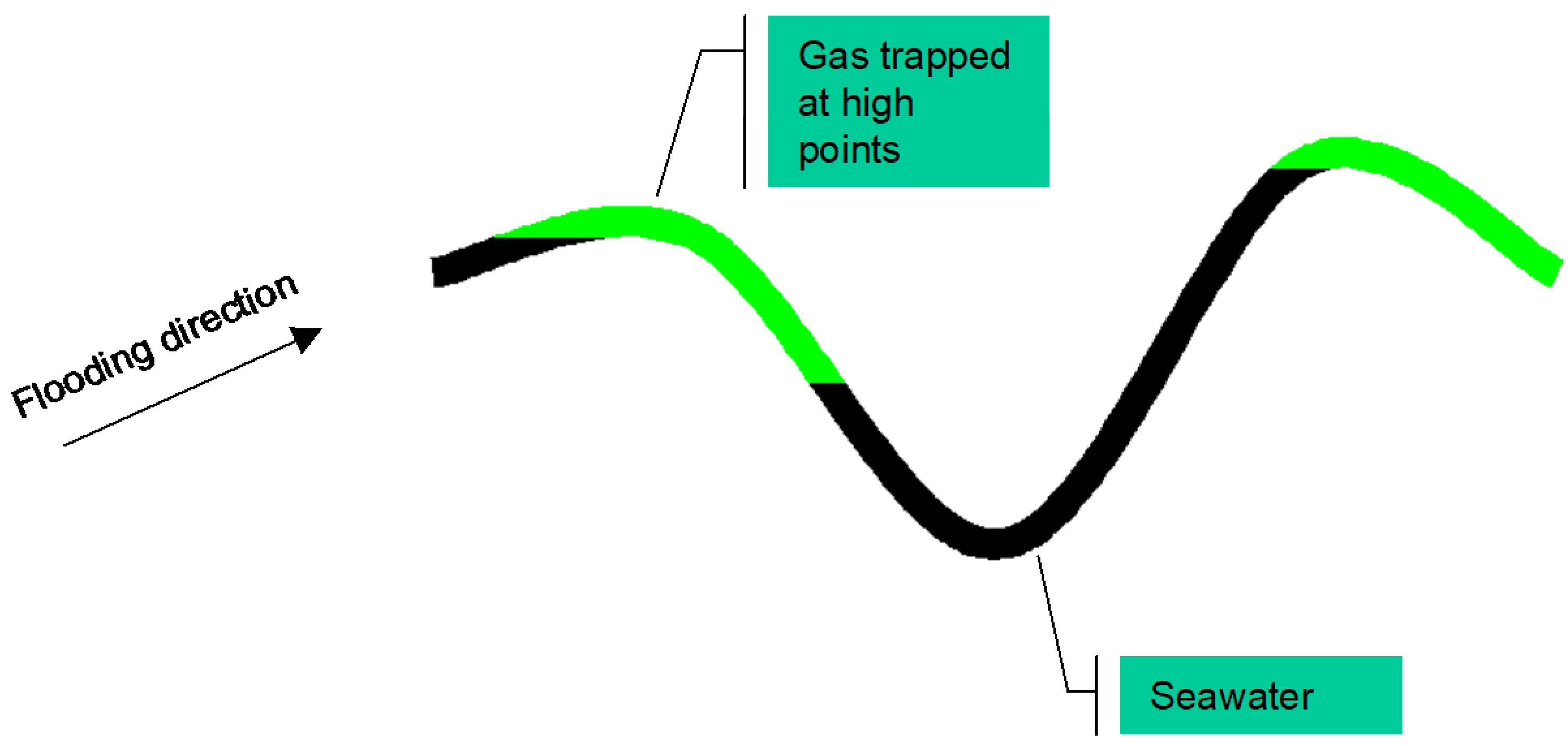
4.7.5. Anti-Hydrate Strategies
- Purge gas from the pipeline before seawater enters the pipeline: This strategy is to maintain sufficient pressure to prevent seawater ingress while mobilizing for further actions. Then hydrocarbons would be displaced using a flooding pig train, consisting (sequentially) of pig, nitrogen, pig, methanol, pig, and seawater. This approach is feasible for small leaks with no associated denting.
- Isolate the pipeline on one or both sides of the leak as necessary to prevent water from running down to depths where hydrate can form: This approach could be applied for a small leak with no associated denting near the landfall. Isolation could be made utilizing a high differential pig train (primary isolation) and an inflatable sphere (secondary isolation). This would prevent seawater from reaching depths in the pipeline where hydrates might form, and it would have the added advantage of avoiding flooding of most of the pipeline. The isolations could be removed following repair by pigging them out with gas when the pipeline is repressurized.
- Maintain as much gas pressure at the pipeline ends as possible to limit flooding: This strategy amounts to simply avoiding unnecessary depressurization at the two ends of the pipeline. This will minimize flooding. This then gives the possibility of (a) sealing the leak in some way and (b) venting the gas trapped at the pipeline ends. In some cases, the venting process may reduce the pipeline pressure sufficiently to dissociate any hydrates that may have formed. This strategy is not an alternative to the others but is considered a generally sensible initial response, for all leak sizes. Other strategies may be applied as well if applicable.
- Reduce pressure (but not below hydrostatic) if the leak is coming from a flange to see whether the leak stops: If the leak from the flange stops on reduction of pressure, then retighten bolts and repressurize the pipeline. This may in some cases resolve the problem; if not, Strategies (1) or (2) should be applied depending on the flange location. Strategies (1) and (2) involve tolerating the leak while mobilizing for repair. A small leak may be hazardous to a small vessel that enters the bubble plume. However, if an effective guard zone arrangement could be rapidly put into place to prevent vessels from approaching the leak site, then relatively large leaks could be tolerated whilst mobilizing for the repair.
5. Conclusions
- Definition of the capabilities of the system.
- Operating manuals for the LDS.
- Roles and responsibilities for operating, maintaining, and testing the leak detection system.
- Requirements for maintenance and testing of the LDS including tasks and frequency.
- What are the expected operational features of the pipeline?
- What are the safety and environmental requirements?
- What risks apply in the case of leaks and what is the role of the LDS in minimizing the consequences of an unexpected leak?
- What are the physical properties of the pipeline and transported fluids?
- Where is the metering located? (Start and end)
- What is the accuracy and location of instrumentation along the pipeline?
- Which is the most appropriate (cost-efficient) LDS for the pipeline?
- What will then be the responsibilities of the operator/user?
- For the Pipeline Monitoring Systems Criteria, the leak detection system should:
- Have acceptable coverage of the entire pipeline system being monitored. There should be no “dead zones” that are not monitored.
- Allow good localization definition of a failure. The resolution of the system should be sufficient to direct repair crews to the failure site.
- Be essentially an “alarm” type system that activates only when a failure has occurred. The monitoring and support crew should be small.
- Installation and operational costs should be acceptable to undersea pipeline users.
- Include a subsea interception system at the riser base (i.e., subsea isolation valve, check valve).
- Design Emergency Shut-Down Valve (ESDV) actuation systems accelerating the system isolation.
Author Contributions
Funding
Informed Consent Statement
Conflicts of Interest
References
- Reda, A.; Shahin, M.A.; Sultan, I.A.; Lagat, C.; McKee, K.K. Incident Case Study of Baseline Pigging During In-Line Inspections for Corrosion Resistant Alloy Clad Pipelines. J. Press. Vessel Technol. 2022, 144, 064503. [Google Scholar] [CrossRef]
- Reda, A.; Sultan, I.A.; Shahin, M.A.; McKee, K.K.; Lagat, C. Fitness-for-service analysis for corrosion-resistant alloy clad pipeline damaged due to lodged intelligent pig. Int. J. Press. Vessel. Pip. 2022, 198, 104683. [Google Scholar] [CrossRef]
- Amaechi, C.V.; Hosie, G.; Reda, A. Review on Subsea Pipeline Integrity Management: An Operator’s Perspective. Energies 2022, 16, 98. [Google Scholar] [CrossRef]
- Agbakwuru, A.J.; Gudmestad, T.O.; Bilstad, T. Experimental study of oil pipeline leak processes. J. Environ. Prot. 2012, 3, 597–604. [Google Scholar]
- Wang, D.; Guo, W.; Kong, S.; Xu, T. Estimating offshore exposure to oil spill impacts based on a statistical forecast model. Mar. Pollut. Bull. 2020, 156, 111213. [Google Scholar] [CrossRef]
- Lu, Y.; Wang, J.; Wei, W.; Yang, Y.; An, W. Development and application of oil-spill risk assessment model for offshore pipeline. J. Ocean Univ. China 2014, 13, 415–420. [Google Scholar] [CrossRef]
- Anderson, C.M.; LaBelle, R.P. Update of comparative occurrence rates for offshore oil spills. Spill Sci. Technol. Bull. 2000, 6, 303–321. [Google Scholar] [CrossRef]
- Offshore Petroleum and Greenhouse Gas Storage (Safety) Regulations; Selective Legislative Instrument No. 382; Department of Industry, Science and Resources: Canberra, Australia, 2009.
- Petroleum (Submerged Lands) (Management of Safety on Offshore Facilities) Regulations; Western Australia: Osborne Park, Australia, 2007.
- Meniconi, S.; Brunone, B.; Tirello, L.; Rubin, A.; Cifrodelli, M.; Capponi, C. Transient tests for checking the Trieste subsea pipeline: Towards the field tests. J. Mar. Sci. Eng. 2024, 12, 374. [Google Scholar] [CrossRef]
- Meniconi, S.; Brunone, B.; Tirello, L.; Rubin, A.; Cifrodelli, M.; Capponi, C. Transient tests for checking the Trieste subsea pipeline: Diving into fault detection. J. Mar. Sci. Eng. 2024, 12, 391. [Google Scholar] [CrossRef]
- AS/NZS 2885.4,2016; Pipelines, Gas and Liquid Petroleum—Part 4: Submarine Pipelines. Standards Australia Store: Sydney, Australia, 2016.
- Rajtar, J.M.; Muthiah, R. Pipeline Leak Detection System for Oil and Gas Flowlines. ASME J. Manuf. Sci. Eng. Febr. 1997, 119, 105–109. [Google Scholar] [CrossRef]
- Kulkarni, M.G.; Buitrago, J.; Arslan, H.; Bardi, F.C. Offshore pipeline leak detection system concepts and feasibility study. In Proceedings of the ISOPE International Ocean and Polar Engineering Conference, ISOPE, Rhodes, Greece, 17–22 June 2012; p. ISOPE-I. [Google Scholar]
- Henrie, M.; Carpenter, P.; Nicholas, R.E. Pipeline Leak Detection Handbook; Gulf Professional Publishing: Houston, TX, USA, 2016. [Google Scholar]
- Turkowski, M.; Bratek, A.; Słowikowski, M. Methods and systems of leak detection in long-range pipelines. J. Autom. Mob. Robot. Intell. Syst. 2007, 1, 39–46. [Google Scholar]
- Gajbhiye, R.N.; Kam, S.I. Leak detection in the subsea pipeline: A mechanistic modelling approach with fixed pressure boundaries. In Proceedings of the Offshore Technology Conference, OTC, Houston, TX, USA, 5–8 May 2008; p. OTC-19347. [Google Scholar]
- Ho, M.; El-Borgi, S.; Patil, D.; Song, G. Inspection and monitoring systems subsea pipelines: A review paper. Struct. Health Monit. 2020, 19, 606–645. [Google Scholar] [CrossRef]
- Hillier, A.; Imtiaz, S.; Khan, F.; Thodi, P. Risk-based evaluation of subsea pipeline leak detection technologies. In Proceedings of the International Conference on Offshore Mechanics and Arctic Engineering, St. John’s, NL, Canada, 31 May–5 June 2015; American Society of Mechanical Engineers: New York, NY, USA, 2015; Volume 56529, p. V05BT04A051. [Google Scholar]
- Cramer, R.; Shaw, D.; Tulalian, R.; Angelo, P.; van Stuijvenberg, M. Detecting and correcting pipeline leaks before they become a big problem. Mar. Technol. Soc. J. 2015, 49, 31–46. [Google Scholar] [CrossRef]
- Davis, P.; Brockhurst, J. Subsea pipeline infrastructure monitoring: A framework for technology review and selection. Ocean Eng. 2015, 104, 540–548. [Google Scholar] [CrossRef]
- Adegboye, M.A.; Fung, W.K.; Karnik, A. Recent advances in pipeline monitoring and oil leakage detection technologies: Principles and approaches. Sensors 2019, 19, 2548. [Google Scholar] [CrossRef]
- Tabella, G.; Paltrinieri, N.; Cozzani, V.; Rossi, P.S. Wireless sensor networks for detection and localization of subsea oil leakages. IEEE Sens. J. 2021, 21, 10890–10904. [Google Scholar] [CrossRef]
- Boaz, L.; Kaijage, S.; Sinde, R. An overview of pipeline leak detection and location systems. In Proceedings of the 2nd Pan African International Conference on Science, Computing and Telecommunications (PACT 2014), Arusha, Tanzania, 14–18 July 2014; pp. 133–137. [Google Scholar] [CrossRef]
- Baroudi, U.; Al-Roubaiey, A.A.; Devendiran, A. Pipeline Leak Detection Systems and Data Fusion: A Survey. IEEE Access 2019, 7, 97426–97439. [Google Scholar] [CrossRef]
- Hu, S.; Feng, A.; Shi, J.; Li, J.; Khan, F.; Zhu, H.; Chen, J.; Chen, G. Underwater gas leak detection using an autonomous underwater vehicle (robotic fish). Process Saf. Environ. Prot. 2022, 167, 89–96. [Google Scholar] [CrossRef]
- DNV-ST-F101; Submarine Pipeline Systems. DNV: Høvik, Norway, 2021.
- DNV-RP-F302; Offshore Leak Detection. Recommended Practice; DNV: Høvik, Norway, 2021.
- Shama, A.M.; Bady, A.; El-Shaib, M.N.; Kotb, M.A. Review of leakage detection methods for subsea pipeline. In Proceedings of the 17th International Congress of the International Maritime Association of the Mediterranean, Lisbon, Portugal, 9–11 October 2017; pp. 9–11. [Google Scholar]
- Odusina, E.; Akingbola, J.; Mannel, D. Software-Based Pipeline Leak Detection; Advanced Chemical Engineering Design CHE 4273; University of Oklahoma: Norman, OK, USA, 2008; Volume 77, p. 13. [Google Scholar]
- Joaristi, M.; Serra, E.; Spezzano, F. Detecting suspicious entities in offshore leak networks. Soc. Netw. Anal. Min. 2019, 9, 62. [Google Scholar] [CrossRef]
- Lukonge, A.B.; Cao, X. Leak detection system for long-distance onshore and offshore gas pipelines using acoustic emission technology. A review. Trans. Indian Inst. Met. 2020, 73, 1715–1727. [Google Scholar] [CrossRef]
- Sulaima, M.F.; Abdullah, F.; Bukhari, W.M.; Ali, F.A.; Nasir, M.N.M.; Yahya, A.B. Oil and gas offshore pipeline leak detection system: A feasibility study. Appl. Mech. Mater. 2015, 699, 891–896. [Google Scholar] [CrossRef]
- Zhiltsov, S.S.; Zonn, I.S.; Kostianoy, A.G. (Eds.) Oil and Gas Pipelines in the Black-Caspian Seas Region; Springer International Publishing: New York City, NY, USA, 2016. [Google Scholar]
- Song, X.; Jian, Z.; Zhang, G.; Liu, M.; Guo, N.; Zhang, W. New research on MEMS acoustic vector sensors used in pipeline ground markers. Sensors 2014, 15, 274–284. [Google Scholar] [CrossRef]
- Bernasconi, G.; Giunta, G. Acoustic detection and tracking of a pipeline inspection gauge. J. Pet. Sci. Eng. 2020, 194, 107549. [Google Scholar] [CrossRef]
- Kim, J.; Chae, M.; Han, J.; Park, S.; Lee, Y. The development of leak detection model in subsea gas pipeline using machine learning. J. Nat. Gas Sci. Eng. 2021, 94, 104134. [Google Scholar] [CrossRef]
- Kammoun, M.; Kammoun, A.; Abid, M. Leak detection methods in water distribution networks: A comparative survey on artificial intelligence applications. J. Pipeline Syst. Eng. Pract. 2022, 13, 04022024. [Google Scholar] [CrossRef]
- Yang, J.; Mostaghimi, H.; Hugo, R.; Park, S.S. Pipeline leak and volume rate detections through Artificial intelligence and vibration analysis. Measurement 2022, 187, 110368. [Google Scholar] [CrossRef]
- Akinsete, O.; Oshingbesan, A. Leak detection in natural gas pipelines using intelligent models. In Proceedings of the SPE Nigeria Annual International Conference and Exhibition, SPE, Lagos, Nigeria, 5–7 August 2019; p. D023S009R001. [Google Scholar]
- ATMOS International Ltd. ATMOS Pipe Software Reference List, Case Studies and Supporting Documents; ATMOS International Ltd.: Manchester, UK, 2010. [Google Scholar]
- Seol, D.-G.; Bhaumik, T.; Bergman, C.; Socolofsky, S.A. Particle Image Velocimetry measurements of the Mean Flow Characteristics in a Bubble Plume. J. Eng. Mech. 2007, 133, 665–676. [Google Scholar] [CrossRef]
- Bettelini, M.S.; Fanneløp, T.K. Underwater plume from an instantaneously started source. Appl. Ocean Res. 1993, 15, 195–206. [Google Scholar] [CrossRef]
- Fannelop, T.; Sjoen, K. Hydrodynamics of underwater blowouts. In Proceedings of the 18th Aerospace Sciences Meeting, Pasadena, CA, USA, 14–16 January 1980; p. 219. [Google Scholar]
- Fanneløp, T.K. Fluid Mechanics for Industrial Safety and Environmental Protection; Industrial Safety Series; Elsevier: Amsterdam, The Netherlands, 1994; Volume 3, pp. 296–305. [Google Scholar]
- Johansen, Ø. DeepBlow—A Lagrangian Plume Model for Deep Water Blowouts. Spill Sci. Technol. Bull. 2000, 6, 103–111. [Google Scholar] [CrossRef]
- Milgram, J.H.; Burgess, J.J. Measurements of the surface flow above round bubble plumes. Appl. Ocean Res. 1984, 6, 40–44. [Google Scholar] [CrossRef]
- Korlapati, N.V.S.; Khan, F.; Noor, Q.; Mirza, S.; Vaddiraju, S. Review and analysis of pipeline leak detection methods. J. Pipeline Sci. Eng. 2022, 2, 100074. [Google Scholar] [CrossRef]
- Cloete, S.; Olsen, J.E.; Skjetne, P. CFD modelling of the plume and free surface behaviour resulting from a sub-sea gas release. Appl. Ocean Res. 2009, 31, 220–225. [Google Scholar] [CrossRef]
- Li, X.; Chen, G.; Zhang, R.; Zhu, H.; Fu, J. Simulation and assessment of underwater gas release and dispersion from subsea gas pipeline leak. Process Saf. Environ. Prot. 2018, 119, 46–57. [Google Scholar]
- API. RP 1175 Pipeline Leak Detection—Program Management; API: Washington, DC, USA, 2015. [Google Scholar]


Disclaimer/Publisher’s Note: The statements, opinions and data contained in all publications are solely those of the individual author(s) and contributor(s) and not of MDPI and/or the editor(s). MDPI and/or the editor(s) disclaim responsibility for any injury to people or property resulting from any ideas, methods, instructions or products referred to in the content. |
© 2024 by the authors. Licensee MDPI, Basel, Switzerland. This article is an open access article distributed under the terms and conditions of the Creative Commons Attribution (CC BY) license (https://creativecommons.org/licenses/by/4.0/).
Share and Cite
Reda, A.; Mahmoud, R.M.A.; Shahin, M.A.; Amaechi, C.V.; Sultan, I.A. Roadmap for Recommended Guidelines of Leak Detection of Subsea Pipelines. J. Mar. Sci. Eng. 2024, 12, 675. https://doi.org/10.3390/jmse12040675
Reda A, Mahmoud RMA, Shahin MA, Amaechi CV, Sultan IA. Roadmap for Recommended Guidelines of Leak Detection of Subsea Pipelines. Journal of Marine Science and Engineering. 2024; 12(4):675. https://doi.org/10.3390/jmse12040675
Chicago/Turabian StyleReda, Ahmed, Ramy Magdy A. Mahmoud, Mohamed A. Shahin, Chiemela Victor Amaechi, and Ibrahim A. Sultan. 2024. "Roadmap for Recommended Guidelines of Leak Detection of Subsea Pipelines" Journal of Marine Science and Engineering 12, no. 4: 675. https://doi.org/10.3390/jmse12040675
APA StyleReda, A., Mahmoud, R. M. A., Shahin, M. A., Amaechi, C. V., & Sultan, I. A. (2024). Roadmap for Recommended Guidelines of Leak Detection of Subsea Pipelines. Journal of Marine Science and Engineering, 12(4), 675. https://doi.org/10.3390/jmse12040675