Article

Sensitivity of Dynamic Response of Truss-Type Aquaculture Platform to Floating Body Arrangement

1
College of Engineering Science and Technology, Shanghai Ocean University, Shanghai 201306, China
2
State Key Laboratory of Structural Analysis for Industrial Equipment, Dalian University of Technology, Dalian 116081, China
3
Shanghai Engineering Research Center of Marine Renewable Energy, Shanghai 201306, China
4
School of Civil Engineering and Architecture, Taizhou University, Taizhou 318000, China
*
Author to whom correspondence should be addressed.
J. Mar. Sci. Eng. 2024, 12(3), 431; https://doi.org/10.3390/jmse12030431
Submission received: 23 January 2024 / Revised: 22 February 2024 / Accepted: 26 February 2024 / Published: 28 February 2024
(This article belongs to the Section Ocean Engineering)

Abstract

:
Aquaculture equipment is moving from offshore areas to the deep sea to obtain a cleaner farming environment, but will suffer from a worse marine environment. Truss-type aquaculture floating platforms have gradually gained the favor of deep-sea and ocean aquaculture due to being resistant to corrosion, lightweight, easy to move, having modular assembly characteristics, and so on. Here, a modular aquaculture floating platform that is mainly composed of high-density polyethylene non-metallic pipes as a floating body, a truss structure support and a single-point mooring system is designed. The three-dimensional potential flow theory and Morison equation are applied to the motion and force prediction of discontinuous and open structures, and an evaluation method for analyzing the hydrodynamic performance of the platform system is proposed. Then, a sensitivity analysis of the dynamic response is conducted on the density and length of the bottom floating pipe arrangement of the truss-type aquaculture floating platform. The results show that the pitch motion of the heading direction and the roll motion of the beam direction have a remarkable effect on the hydrodynamics of the truss-type aquaculture floating platform, and the maximum amplitude is 12.9 deg and 10.8 deg, respectively. The effective tension under the heading direction is greater than that under the Beam direction. And the sparser the arrangement of the floating pipe is and the longer the length of the floating pipe is, the more improved the hydrodynamic performance of the floating platform will be, but the effective tension is greatly affected by the wavelength and period, so it is necessary to design the appropriate floating pipe length according to the actual marine environment. This study could provide an engineering reference for the design, analysis, and application of an aquaculture floating platform.

1. Introduction

The demand for shellfish and algae aquatic products such as oysters is increasing with the improvement of living standards, and the increase in the output of aquatic products mainly depends on marine fisheries [1,2,3,4]. However, in recent years, the offshore environment has been severely polluted, with the excessive concentration of aquaculture leading to a gradual decline in the quality and production of aquatic products [5,6,7,8]. Therefore, moving towards the deep sea and developing new models of open marine aquaculture to accelerate large-scale food production are effective methods to address these problems. Currently, most deep-sea aquaculture equipment comprise net cages [9], and most of them are designed for the large structure and high capacity of aquaculture fish products. For small-scale aquatic products such as shellfish and algae, oyster cages and hanging ropes are generally used for offshore aquaculture [10]. For example, a suspended aquaculture system was designed in Belgium early on to promote mussel farming; this comprised a 200 m long extension rope with a buoy, two anchors, and 20 polypropylene ropes, each of which was 5 m long and 12 mm thick, as shown in Figure 1. In addition, an IMTA platform was designed by the University of New Hampshire for marine fish, shellfish, and seaweeds; this uses the truss structure, as shown in Figure 2. At present, there is a lack of deep-sea aquaculture equipment specially designed for shellfish and algae [11].
Research on the motion and mooring force of deep-sea aquaculture equipment is the premise of its safe application in the ocean, and theoretical and experimental methods are commonly used to check [12]. Regarding the motion research of offshore platforms, three-dimensional potential flow theory is one of the theories frequently used to analyze hydrodynamic performance [13]. Zan et al. [14] calculated the additional mass, damping coefficient, and ship motion response of a deepwater-pipeline-laying ship under the condition of regular waves by utilizing three-dimensional potential flow theory and three-dimensional non-velocity frequency domain Green’s function. Kristiansen et al. [15] found, through experimental research on aquaculture equipment in waves and currents, that the wave-induced forces on the model were counteracted in many wave cycles. James et al. [16] conducted research on the force and motion of seawater on aquaculture equipment through model and prototype tests. Shuo and Zhi [17] proposed a multi-objective optimization model and calculation method for trimaran motion response under regular waves based on potential flow theory and the Monte Carlo method. Based on the potential flow theory, Dombre et al. [18] introduced the boundary element method to study the development and verification of the wave–structure interaction in a three-dimensional numerical wave flume. Based on the arbitrary Lagrangian–Euler method, which is based on the fully nonlinear potential flow theory, Zhang et al. [19] imitated the wave–structure interaction under extreme sea conditions in a three-dimensional hybrid model and found that highly nonlinear nondestructive water waves can be accurately simulated in a large range with high computational efficiency. Liu et al. [20] applied the boundary element method, combining the Morison equation with potential flow theory, to the hydrodynamic response analysis of aquaculture facilities. Saincher and Sriram [21] established a three-dimensional hybrid fully nonlinear potential flow and Navier Stokes model for wave–structure interactions that was suitable for simulating complex interactions between waves and large-scale moving objects. Tao et al. [22] used experimental and computational fluid dynamics (CFD) methods to study the hydrodynamic performance of a new type of deep-sea aquaculture ship. However, research on the hydrodynamic performance of a truss-type aquaculture floating platform in the deep sea is still limited.
For the safe production and operation of the aquaculture platform, the wind, waves, and current of the deep sea are severe challenges, so a mooring system for the aquaculture equipment is strictly required. A single-point mooring system is generally used because of its drift effect, which significantly reduces the amount of seafloor sediment waste in aquaculture and plays a positive role in protecting the marine environment. Kim et al. [23] proposed the use of the time-domain analysis method to study the coupling of the mooring system of the Floating Production Storage and Offloading, obtained the hydrostatic force parameters and the motion response amplitude operator of the platform, and studied the motion response and dynamic characteristics of mooring ropes. Huang et al. [24] used numerical simulation and experimental methods to set up sensors on a single-point mooring cage system to study the dynamic response, and used the lumped mass method and mesh plane elements to simulate dynamic motion to study the tension response of mooring rope. Rudman and Cleary [25] introduced the time domain analysis method to work out the mooring force of the mooring lines of floating structures and studied the dynamic response. Ja et al. [26] found that the material properties of the mooring system have a remarkable effect on the behavior of the mooring system, and that the restoring force of the mooring system increases with the increase in the mooring stiffness. Duan et al. [27] built a fully coupled dynamic analysis model for the mooring system of an underwater production platform and analyzed its coupling effect, dynamic response characteristics, and safety risks; they found that its dynamic response to internal solitary waves had the significant characteristics of surge and heave motion, and that its mooring tension fluctuated significantly. Wu et al. [28] conducted a series of studies on ship motion and mooring rope tension by employing the numerical simulation method and found that mooring line failure can have a notable influence on ship performance, potentially threatening the safety of the floating system. Based on the slender structure of the cage array, Zhongchi et al. [29] used the Morison equation to calculate the hydrodynamic load and evaluated the mooring force of the system under different sea conditions. Yu et al. [30] suggested a numerical evaluation method for hydrodynamic loads on aquaculture platforms based on traditional potential flow theory and the Morison equation. It was discovered that there are many studies on the hydrodynamic performance and mooring calculation of offshore equipment, but in practical application, most research only focuses on floating structures with a closed continuous water surface. However, there are relatively few studies on the motion and force of discontinuous and open structures. For this kind of waterplane discontinuous and open floating structure with large-scale longitudinal members and small-scale transverse members, if the three-dimensional potential flow theory is used alone, the calculation will be time consuming if the element is too small due to the limitation of small-scale components. However, the result is not convergent due to the excessive size of the element.
In this paper, a modular aquaculture floating platform that is mainly composed of high-density polyethylene non-metallic pipes, a truss structure support and a single-point mooring system is designed. And a dynamic response evaluation method for the truss-type aquaculture platform is proposed. The three-dimensional potential flow theory and Morison equation theory are applied to the motion and force prediction of discontinuous and open structures. Therefore, the truss structure in this paper is composed of a longitudinal continuous three-dimensional potential flow surface element and a transverse Morrison beam, and the calculation method is innovative. Then, the hydrodynamic performance and anchoring characteristic of the floating platform under the operation sea conditions are obtained based on numerical simulation. Finally, a sensitivity analysis is conducted on the density and length of the bottom floating pipe arrangement of the truss-type aquaculture floating platform. This study could afford a reference for the design and application of related truss-type aquaculture equipment.

2. Theory and Methodology

2.1. Motion Responses

The potential flow theory has achieved satisfactory results in studying wave forces, and so has rapidly developed in ocean engineering. For the motion response of large-scale components, it will have a significant impact on incident waves in seawater, with the most significant effects being diffraction and reflection effects [31].
(1)
Basic assumption
The following assumptions are given: The fluid is an ideal fluid, being inviscid, uniform, and incompressible, with no rotation in motion; the incident wave adopts the linear small-amplitude wave theory, and the wave motion on the free surface and the motion of the structure are micro amplitude.
(2)
Velocity potential
The water depth h remains constant, the O X Y plane of the coordinate system O X Y Z concurs with the static water surface, and the O Z axis is vertically upward; the free surface can be represented as follows:
z = η ( x , y , t )
where t is time, x , y , z are the 6DOF motion vectors, and η is the wavefront fluctuation. Under the assumed condition of the small-amplitude wave, the wavefront fluctuation η is a small quantity; this is used to linearize the kinematic and dynamic conditions of the free surface.
Using the velocity potential Φ ( x , y , z , t ) to depict the flow field, it satisfies the following conditions.
Laplace’s equation is satisfied in the basin:
Δ Φ = 0
Impermeability of the seabed:
Φ z = Φ z = 0 , ( z = h )
Dynamic conditions of free surface:
Φ t + 0.5 ( Φ ) 2 + p p a ρ + g z = 0 , ( z = η ( x , y , t ) )
Kinematics conditions of free surface:
η t + Φ x η x + Φ y η y = Φ z , ( z = η ( x , y , t ) )
Under the condition of the small-amplitude wave, the wavefront fluctuation η is small, and the velocity of fluid particles in the wave is also small, so the high-order small quantity containing η can be omitted. According to the conservation theorem of a continuous fluid line, the velocity of a point on the free surface is equal to that of the fluid particle on the free surface, and the pressure on the free surface must be equal to the pressure of the atmosphere above the free surface, so it satisfies the following equation:
2 Φ t 2 + g Φ t = 0 , ( z = 0 )
Because the wave motion of the free surface and the motion of the floating body are small, the velocity potential of the flow field with a floating rigid body in the wave with harmonic propagation can be regarded as linear, so the velocity potential in the flow field can be expressed by the superposition of three parts:
Φ x , y , z , t = Φ I + Φ D + Φ R
where Φ I is the incident potential of the wave disturbed by a floating body, Φ D is the wave diffraction potential caused by the wave passing through the floating body, and Φ R is the radiation potential, which is produced by the oscillating motion of the floating body.
If it is assumed that the structure oscillates slightly around the equilibrium position, the above velocity potential can be broken down into the product of the space velocity potential ϕ ( x , y , z ) and the time factor e i ω t :
Φ x , y , z , t = Re { ϕ ( x , y , z ) e i ω t }
Similarly, the incident potential, the diffraction potential and the radiation potential can be expressed as follows:
Φ I x , y , z , t = Re { ϕ I ( x , y , z ) e i ω t }
Φ D x , y , z , t = Re { ϕ D ( x , y , z ) e i ω t }
Φ R x , y , z , t = Re { ϕ R ( x , y , z ) e i ω t }
That is, after separating the time factor, the spatial velocity potential can be expressed as the linear superposition of the incident potential, diffraction potential and radiation potential, as follows:
ϕ x , y , z = ϕ I x , y , z + ϕ D x , y , z + ϕ R x , y , z
Green’s function method can also be used to solve the Laplace equation under definite boundary conditions, as shown in Formulas (2)–(5) above. The free surface source potential is selected as the Green function, and the total velocity potential can be obtained by calculating the above boundary conditions using Green’s Theorem; then, the pressure distribution on the surface of the object can be obtained, and finally the wave force and moment acting on the object can be obtained, as follows:
Wave force:
F t o t a l =   s ρ Φ I t + Φ D t + Φ R t + g z γ d s = F I + F D + F R + F S
And moment:
M t o t a l = M I + M D + M R + M S
where s is the wet surface of the floating body and γ is directed to the fluid load from inside the floating body. F R and M R are the radiation loads caused by the forced vibration of the floating body, F I and M I are the loads caused by the incident waves, F D and M D are the loads caused by the diffracted waves, and F S and M S are hydrostatic loads.
The dynamic equations of the culture platform under free movement in the frequency domain are as follows:
M + Δ M X + B X + K X = 0
where X is the displacement of the floating body, M is the mass or inertia mass of the culture platform, Δ M is the additional mass or inertia mass, B is the damping, and K is the restoration stiffness.
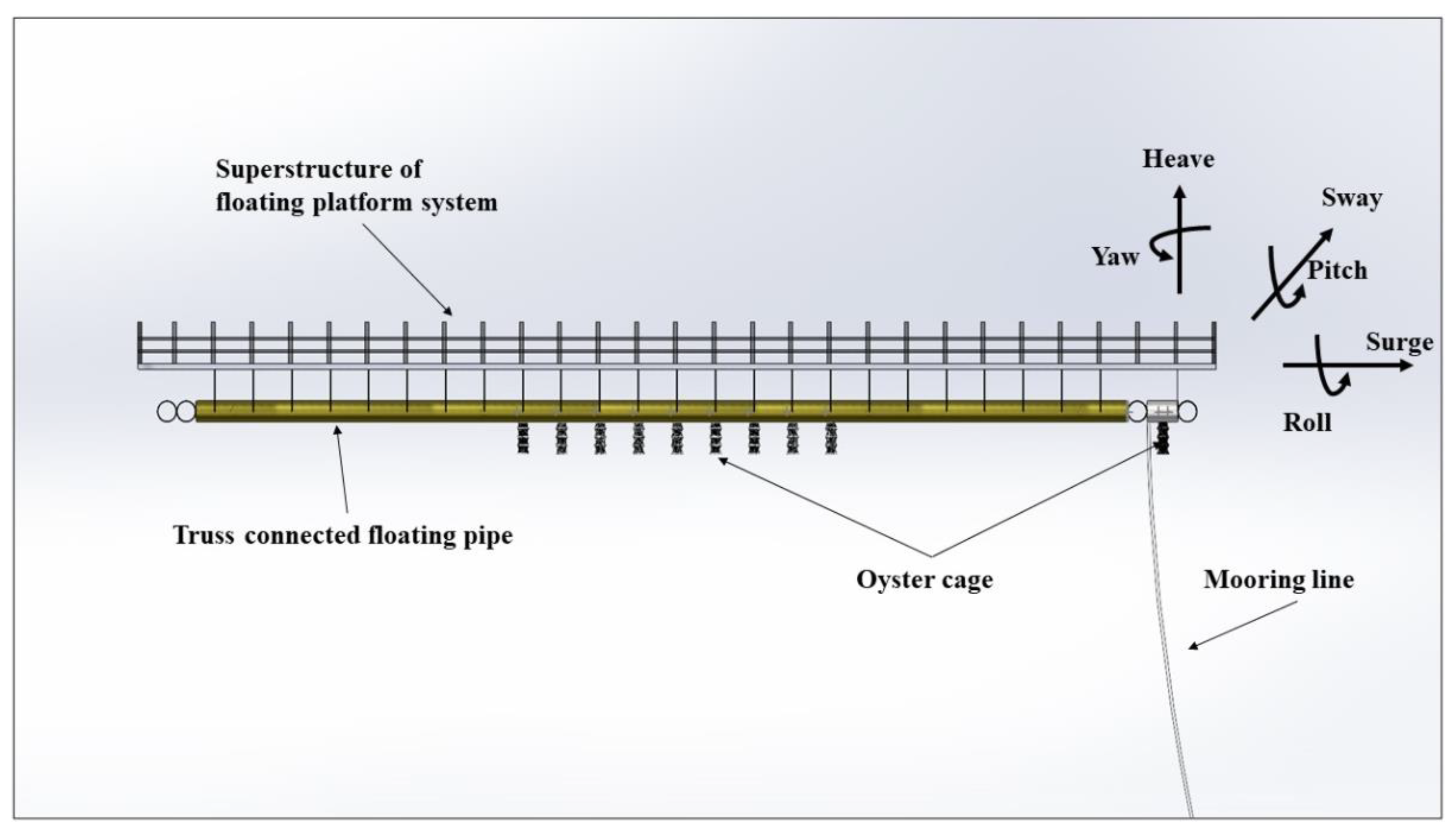
The floating platform motion response amplitude operator (RAO) refers to the rate of the displacement of the floating body in the direction of freedom degree to the wave amplitude, which represents the floating body’s motion response characteristics based on the action of linear waves. Mathematically, the formula is as follows:
R = d / a cos ω t ϕ
where d is the displacement of the floating body (in length units for surge, sway, heave, in degrees for roll, pitch, yaw), a is the wave amplitude, ω is the frequency, t is time, R is the response amplitude operator (RAO) amplitude and ϕ is the RAO phase.

2.2. Environmental Loads

The wave-induced loads acting on the platform structure are caused by the pressure field generated by waves [32,33]. For the convenience of subsequent calculations, the wave-induced load is divided into three parts in this paper. For small-scale structures, the drag and inertia forces of waves are the main components. The wave loads on such structures can usually be calculated using the Morison equation, where the total wave force acting on a slender rigid body can be expressed as the sum of resistance F Re and inertia forces F I n , and the resistance term is taken as a function of velocity.
According to Marine Structural Design [34] and Wu et al. [35], the Bretschneider wave spectrum was used to display the random wave characteristics and analyze the response of flexible pipes in the marine environment. The Bretschnerder spectrum is a two-parameter spectrum composed of a period and wave height, and the two parameters can be specified, respectively. Its form is as follows:
S ω = 0.6187 H s 2 ω s 4 ω 5 exp 0.675 ω s / ω 4
ω s = 2 π T s , T s = 0.946 T 0
where T s , and T 0 are the significant wave period and the peak period, respectively. H s is the significant wave height.
For small-scale structures, the drag and inertia forces of waves are the main components. The wave loads on such structures can usually be calculated using the Morison equation [30], where the total wave force acting on a slender rigid body can be expressed as the sum of resistance F Re and inertia forces F I n , and the resistance term is taken as a function of velocity.
F T = F Re + F I n
Among them,
F Re = 1 2 ρ C D A u u
F I n = ρ C M V u ·
where A is the projected area of the object, V is the volume of the object, ρ is the density of the object, u is the velocity of the fluid, a dot u · is the acceleration of the fluid, C D is the resistance coefficient, and C M is the coefficient of inertia.
Based on the assumption of the small-amplitude wave, the value of the second-order wave force is much smaller than that of the first-order wave force, so the effect of the second-order wave force is not considered in the subsequent calculation. The time domain motion equation of a floating body is as follows [12,36,37]:
m + Δ m x · · t + t K t τ x · t d τ + C x t = F ω t + F w i n d + F c + F s n t + F m t
where m , Δ m are the inferred mass matrix and additional mass matrix of the floating body, respectively; K (   t τ ) is the delay function matrix of the system; C is the hydrostatic restoring force coefficient matrix of the floating body; F ω t is the first-order wave force; F w i n d is the wind resistance; F c is the current flow force; F s n t is the second-order wave force; and F m t is the mooring force.
The effect is assumed to be linear superposition. Currently, the empirical formula for the wind force F w i n d calculation is as follows:
F w i n d = 0.5 ρ w A w C d w u w   2
where F w i n d is the wind resistance; ρ w is the air density; A w is the upwind area; u w is the relative velocity between the pipe section and the wind; and C d w is the wind resistance coefficient.
The formula for calculating the current flow force F c is as follows:
F c = 0.5 ρ c A c C d c v 2
where F c is the current flow force; ρ c is the sea water density; A c is the area of the upstream; v is the relative velocity between the floating body and the current; and C d c is the water resistance coefficient.
Please refer to the book OFFSHORE HYDROMECHANICS [37] for detailed theoretical derivation.

2.3. Performance Evaluation Method

The three-dimensional potential flow theory and Morison equation theory are applied to the motion and force prediction of discontinuous and open structures. And a performance evaluation method of a truss-type floating platform designed for deep-sea shellfish and algae aquaculture is proposed, as shown in Figure 3. Firstly, a design scheme based on the technical requirements is provided. Secondly, the numerical model is established in Ansys-APDL (version 18.0) software, and the corresponding initial condition and boundary conditions are set. The model is inputted into the Ansys-AQWA module, and the frequency domain motion of the model is solved by the AQWA module, and the RAOS value of the floating platform is calculated. Then, the model and the results of the frequency domain analysis are input into OrcaFlex (version 9.7) software for the mooring force analysis, and the time domain analysis results for the mooring force are obtained. In this paper, the time domain calculation method is mainly used, and the RAOS value calculated in the frequency domain is input into the time domain calculation as the initial motion. Finally, the performance of the floating platform is evaluated. To optimize the design scheme, it is necessary to execute hydrodynamic analysis and mooring line force analysis on the floating platform and summarize the motion response of the floating platform system and the variation law of the mooring force of the cable under different sea conditions.

3. Case Study

The designed truss-type floating platform for shellfish and algae culture is mainly made of HDPE, which can effectively shorten the construction dead weight of the floating platform. Utilizing the application of three-dimensional potential flow theory on the wet surfaces of large longitudinal continuous structures such as ships, combined with research on the beam structure forces of deep-sea equipment under the Morison equation, the aquaculture floating platform adopts a truss structure to ensure the hydrodynamic performance and reduce the mooring force.

3.1. Scheme Design

According to design requirements of DNV-ST-F119 (Det Norske Veritas-Standard-document code F119, the standard of thermoplastic composite pipes) [38] and DNV-OS-E301 (Det Norske Veritas-Offshore Standard-document code E301, the offshore standard of position mooring) [39], the designed floating platform scheme parameters are given based on the technical indicators outlined in Table 1.
The bending resistance of this new type of composite pipe (HDPE) is stronger than that of the traditional PE pipe, and the hydroelasticity problem caused by large deformation is not considered in this paper.
The global structural design diagram is shown in Figure 4; this keeps the lift port of the underwater aquaculture tank in the middle, with the water part equipped with the production equipment system and the studio, so the floating aquaculture platform can be used alone or for large-scale aquaculture, making it suitable for various scale aquaculture needs. The local structure diagram of the floating platform is given in Figure 5, and the oyster cage layout diagram is given in Figure 6.
After multiple modifications and optimizations of the floating bottom pipe, design case 1 is shown in Figure 7.

3.2. Numerical Model

According to design case 1 (Figure 7), a floating pipe model of the bottom layer of the aquaculture floating platform is established. And the weight of the superstructure, the operating load, the weight of the floating pipe and the additional weight above the floating pipe are evenly distributed on the floating pipe, with oyster cages as mass points distributed in the working area. The center of gravity position and mass matrix data are considered and calculated in AQWA (version 18.0) software based on the model mass distribution. Among them, the transversal beams are set as Morison beams with a diameter of 200 mm and the longitudinal beams with a diameter of 500 mm are set as three-dimensional potential flow surface elements. And the mesh size of 3D potential flow panels is set to 0.3 m, with a center of gravity of (0, −0.418 mm, 0.707 mm). The numerical model of the bottom floating pipe structure is shown in Figure 8.

3.3. Experimental Data vs. Numerical Model

In order to ensure the accuracy of the numerical model calculation, it is necessary to verify and analyze the numerical model combined with the experimental results according to the motion and mooring force of the truss floating platform. Many scholars have carried out research on the effectiveness of hydrodynamics software to predict the motion and mooring force of floating structures. For example, Wang et al. [40] calculated the floating body model in the frequency domain by using the hydrodynamic software AQWA, and analyzed the hydrodynamic response of floating offshore equipment. Tongphong et al. [41] used the finite element analysis software Ansys-AQWA to simulate the wave energy converter under the condition of regular waves, analyzed its motion characteristics and optimized its performance. Pang et al. [42] developed a new type of single-point moored semi-submersible ship-shaped truss fish farm platform, and analyzed the dynamic response of the platform under different wave conditions based on the verified numerical model. The results show that the new semi-submersible boat-shaped fish culture platform has good adaptability to extreme sea conditions. In a prediction study of the elastic mooring force and dynamic motion of a multi-floating hinged WEC in a nonlinear mooring system, through a comparison of the results of OrcaFlex and the experimental scale model, Chenyu et al. [43] found that the results were in good agreement. This shows that various nonlinear modes of mooring cables can be simulated accurately by using OrcaFlex simulation. These studies show that it is feasible and effective to use the numerical simulation method to study the hydrodynamic response and mooring force of floating platform systems.
Here, the tank model test is carried out to verify the feasibility of the model composed of longitudinal continuous three-dimensional potential flow surface elements and a transverse Morrison beam in Ansys-AQWA and OrcaFlex software. And the material density and wall thickness are adjusted to ensure the similarity of the principal scale, weight and center of gravity of the model. The similarity between the experimental model and the new numerical model is 1:30. The parameters of the experimental model and the numerical model are shown in Table 2 below.
The dimensions of the test tank are as follows: 70 m in length, 40 m in width, and 1.5 m in depth. The maximum flow velocity and wave height are 1.25 m/s and 0.30 m, respectively, and the wave period range is from 0.3 to 5.0 s.
The field experiment is shown in Figure 9. Three points are fixed on the experimental model by using image recognition technology to analyze the motion amplitude. The experimental conditions are given in Table 3. By using the waterproof dynamometer with a measuring range of 5 N, the drag force acting on the truss structure is measured and the sampling time of the working condition data is 60 s. The numerical model is shown in Figure 10.
The comparison method for calculating the single maximum peak in the time interval is used. In the comparison between the experiment and the model, the maximum rotation angle and mooring force variables are selected for comparison. The relationship between the experimental and numerical results of the pitch motion and mooring force of Test 1 (flow velocity is 0.04 m/s), Test 2 (flow velocity is 0.05 m/s) and Test 3 (flow velocity is 0.06 m/s) is shown in Figure 11.
It can be seen that, with the increase in the environmental parameters, the mooring force of the floating platform increases, while the rotation angle in the pitching direction decreases. The experimental data are in good agreement with the numerical values. The relative error between the numerical and the experimental values is less than 20%. This shows that the performance evaluation method that is given in this paper could be used to analyze the sensitivity of the dynamic response of the truss-type aquaculture platform to the floating body arrangement.

4. Result Analysis

In this paper, the total calculation time is 3600 s, and the time step size test is carried out by using time steps of 10 s, 1 s and 0.1 s. It is found that the results of 10 s and 1 s are divergent; the results converge and there is no peak leakage under the step size of 0.1 s. The time step size is set as 0.1 s.

4.1. Motion Response Result

The more significant time–history curves of surge, heave and pitch in the heading direction and heave and roll in the beam direction are shown in Figure 12 and Figure 13, and the movements of other degrees of freedom are very small.
(1)
Heading direction
Figure 12. The time history curves of the surge, heave, and pitch in the heading direction (180°).
Jmse 12 00431 g012aJmse 12 00431 g012b
(2)
Beam direction
Figure 13. The time history curves of the heave and roll in the beam direction (90°).
Jmse 12 00431 g013
As shown in Figure 12 and Figure 13, under the heading condition, the variation ranges of the surge, heave and pitch of the floating platform are 6.2 m, 3.7 m and 12.9 deg. And under the beam condition, the variation ranges of the heave and roll of the floating platform are 3.8 m and 10.8 deg. The motion of surge, heave and pitch in the heading direction and heave and roll in the beam direction have a great impact on the hydrodynamic performance of the floating platform. And the corresponding results provide input data for the mooring force calculation.

4.2. Force Result of Mooring Rope

The single-point mooring system is adopted in this paper, and the water depth is approximately 30 m. The mooring line is connected to the seabed anchor, with a horizontal length of 97 m and a mooring rope length of 103 m. The model diagram is shown in Figure 14.
Here, three kinds of sea conditions and two types of incoming flow directions are considered, namely sea state 2, sea state 4 and sea state 7, as well as the directions of incoming flow: heading direction and beam direction. The specific sea condition parameters are obtained from on-site monitoring data, as shown in Table 4. The random and irregular wave fields under different sea conditions are simulated using the Bretschneider spectrum. According to DNV-RP-C205 (Det Norske Veritas-Recommended Practice-document code C205, the recommended practice of environmental conditions and environmental loads) [44], the relevant parameters of the floating platform and mooring rope are selected; the typically added mass coefficient is 1, the average drag mass coefficient is 1.2, and so on.
The calculated results for the mooring forces are shown in Figure 15, Figure 16 and Figure 17.
(1)
Effective tension results of sea state 2
Figure 15. (a) Sea state 2—heading direction. (b) Sea state 2—beam direction.
Jmse 12 00431 g015
(2)
Effective tension results of sea state 4
Figure 16. (a) Sea state 4—heading direction. (b) Sea state 4—beam direction.
Jmse 12 00431 g016
(3)
Effective tension results of sea state 7
Figure 17. (a) Sea state 7—heading direction. (b) Sea state 7—beam direction.
Jmse 12 00431 g017
The maximum effective tensions of the mooring system are given in Table 5 below.
As shown in Table 5, it can be found that the floating truss-type platform could operate normally below sea state 4 (DNV-OS-E301, 2021) and that the maximum effective tension of the mooring system does not exceed 14.2 kN. Under the same sea state, the effective force of the heading direction is greater than that of the beam direction. Specifically, there is a maximum effective force of up to 200 kN under the heading direction condition of sea state 7. According to the bearing capacity parameters of the mooring rope given in Table 1, the cable of the floating truss platform will not be broken under sea state 7, meeting the requirements for safe operation.

5. Sensitivity of Dynamic Response to Floating Body Arrangement

To study the hydrodynamic performance of the truss aquaculture floating platform in a complex marine environment, the performance of different floating platform design schemes is analyzed according to the motion amplitude and mooring force, and the effects of the sparse density and length of the bottom floating pipe arrangement are compared.

5.1. Comparison of Sparse Density in Pipe Layout

The effects of the same principal scale but different pipe sparse densities on the hydrodynamic performance and mooring force are studied. Each scheme is left and right symmetrical, in which case 1, case 2 and case 3 are the average distribution of five pipes per side, six pipes per side, and seven pipes per side, respectively. The arrangement of different sparse densities is shown in Figure 18 below.
As shown in Figure 18, the sparse density of the bottom floating pipe layout in three cases complies with the buoyancy requirements. The maximum time domain response results of the three cases under the 7th sea state are shown in Figure 19 below.
As seen from Figure 19, the motion of the case 1 which is the average distribution of five pipes per side is the smallest; under the condition of the heading wave, the angle change of the three schemes is quite different, in which the angle of the sparse density with five pipes is the smallest. Meanwhile, under the condition of the beam wave, the angle change of the three schemes is relatively small. Therefore, the hydrodynamic performance of the floating platform decreases with the increase in pipeline density.
According to the mooring force results in Table 6, it is shown that under the heading direction of sea state 7, the maximum effective tension of case 1 (sparse density of five pipes) is the smallest and the effect is the best.
The results illustrate that the sparser the floating pipe arrangement is, the smaller the translation and rotation angle of the floating platform is. Similarly, the maximum effective tension of case 1 on the floating platform is also the minimum, so that the performance of the mooring system is the best.

5.2. Comparison of Length in Pipe Layout

The effects of the same principal scale but different design lengths on the hydrodynamic performance and mooring force are studied. Case 1 has a total length of 23 m, case 4 has a total length of 24 m, case 5 has a total length of 25 m, case 6 has a total length of 26 m, and case 7 has a total length of 27 m. The arrangement of different total lengths in the pipe layout is shown in Figure 20 below.
As shown in Figure 20, the design lengths of the five types of floating platforms meet the buoyancy requirements. The maximum time domain response results of the three cases under the 7th sea state are given in Figure 21.
As shown in Figure 21, the translation and rotation angle of case 7 are relatively small under the condition of the heading wave and beam wave. Therefore, with the increase in the pipeline length, the translation distance and rotation angle of the floating platform decrease as a whole, indicating that the hydrodynamic performance of the floating platform increases with the increase in the pipeline length.
According to the mooring force results shown in Table 7, under the beam direction of sea state 7, the maximum effective tension of case 5 is the smallest, at 175.35 kN. Case 1 is at a moderate level, at 200 kN.
By comparing the motions and forces under the conditions of the heading and beam direction, it is concluded that when the design length of the floating pipe is longer, the hydrodynamic performance of the floating platform is improved. As the effective tension of longitudinal structures with different lengths is greatly affected by the wavelength and period when heading waves, the selection of an appropriate floating pipe length needs to be comprehensively considered in conjunction with practical engineering.

6. Conclusions

In this paper, truss-type equipment for deep-sea shellfish and algae aquaculture is designed; this is a structural innovation design based on a suspension aquaculture system and aquaculture raft. The three-dimensional potential flow theory and Morison equation are adopted as a combination of theoretical research and numerical simulation methods to study the motion and force prediction of discontinuous and open structures. Then, an evaluation method for analyzing the hydrodynamic performance of the platform system is proposed, and a sensitivity analysis is conducted on the sparse density and length of the bottom floating pipe from the perspectives of the hydrodynamic performance and mooring force. The main conclusions are as follows.
(1)
The truss structure consists of the transversal Morison beam and the longitudinal three-dimensional potential flow surface element. And the oyster cage is distributed as the mass point in the working area. Compared with the experimental data, the performance evaluation method that is given in this paper could be used to analyze the sensitivity of the dynamic response of the truss-type aquaculture platform to the floating body arrangement.
(2)
The aquaculture floating platform could operate normally under level 4 sea conditions, and the rope will not be broken under level 7 sea conditions. The maximum amplitude of the pitch and roll angles are 12.9 deg and 10.8 deg, respectively. And the effective tension of the floating platform structure under the heading direction is greater than that under the beam direction, and the effective tension under the heading direction of sea state 7 is as high as 200 kN.
(3)
The sparsity and design length of the floating pipe arrangement are the key factors affecting the dynamic response of the floating platform. The sparser the floating pipe arrangement is, the smaller the translation and rotation angle of the floating platform are. And when the length of the floating pipe is longer, the hydrodynamic performance of the floating platform is better; however, its maximum effective tension is greatly influenced by the wavelength and period, so the appropriate length should be selected based on the actual engineering requirements.

Author Contributions

Conceptualization, Y.C. and Z.L.; methodology, software, validation, Z.L.; formal analysis, K.W.; investigation, Y.C. and Z.L.; resources, Q.Y.; data curation, Y.C. and Z.L.; writing—original draft preparation, Y.C. and Z.L.; review, editing, and project administration, Y.C., Z.L. and K.W.; funding acquisition, Y.C. All authors have read and agreed to the published version of the manuscript.

Funding

This research was support by the National Key R&D Program of China (No.2021YFC2802300), and the National Natural Science Foundation of China (Grant No. 52371282), and the Open Fund of State Key Laboratory of Structural Analysis for Industrial Equipment (Dalian University of Technology, No. GZ22113), and the Open Fund of Zhejiang Key Laboratory of Marine Geotechnical Engineering and Materials (Zhejiang University, No. OGME21002).

Institutional Review Board Statement

Not applicable.

Informed Consent Statement

Not applicable.

Data Availability Statement

The data used to support the findings of this study are included in the article.

Conflicts of Interest

The authors declare no conflict of interest.

References

  1. Liu, H.H.; Peng, D.M.; Yang, H.J.; Mu, Y.T.; Zhu, Y.G. Exploring the evolution of sustainable fisheries development: Focusing on ecological, environmental and management issues. Ecol. Inform. 2023, 75, 102004. [Google Scholar] [CrossRef]
  2. Nenciu, M.; Nita, V.; Lazar, L.; Spinu, A.; Vlasceanu-Mateescu, E. Fostering the Development of Western Black Sea Aquaculture: A Scientific Case Study for Finfish Cage Farming Allocated Zone Designation. Fishes 2023, 8, 104. [Google Scholar] [CrossRef]
  3. Pholchan, M.; Kaewseesuk, K.; Klayraung, S.; Sompong, U. Effect of Light Intensities and Atmospheric Gas Conditions on Biohydrogen Production of Microalgae Isolated from Fisheries Wastewater. Environ. Nat. Resour. J. 2017, 15, 21–29. [Google Scholar] [CrossRef]
  4. Zhao, Q.L.; Chen, X.J.; Chen, G.Y.; Qi, S.Q. Understanding the development of recreational fisheries with an industry competitiveness framework: Evaluation of a case study from China. Mar. Policy 2022, 143, 105121. [Google Scholar] [CrossRef]
  5. Wanja, D.W.; Mbuthia, P.G.; Waruiru, R.M.; Mwadime, J.M.; Bebora, L.C.; Nyaga, P.N.; Ngowi, H.A. Fish Husbandry Practices and Water Quality in Central Kenya: Potential Risk Factors for Fish Mortality and Infectious Diseases. Vet. Med. Int. 2020, 2020, 6839354. [Google Scholar] [CrossRef] [PubMed]
  6. Li, Y.T.; Kong, J.J.; Ji, J.Y. Environmental Regulation, Technological Innovation and Development of Marine Fisheries-Evidence from Ten Coastal Regions in China. Fishes 2022, 7, 20. [Google Scholar] [CrossRef]
  7. Ma, Z.; Qin, J. New Techniques in Marine Aquaculture. J. Mar. Sci. Eng. 2023, 11, 2239. [Google Scholar] [CrossRef]
  8. Cahill, B.V.; McCulloch, K.L.; DeGroot, B.C.; Bassos-Hull, K.; Ajemian, M.J. Breaking bags and crunching clams: Assessing whitespotted eagle ray interactions with hard clam aquaculture gear. Aquac. Environ. Interact. 2023, 15, 59–71. [Google Scholar] [CrossRef]
  9. Besson, M.; de Boer, I.J.M.; Vandeputte, M.; van Arendonk, J.A.M.; Quillet, E.; Komen, H.; Aubin, J. Effect of production quotas on economic and environmental values of growth rate and feed efficiency in sea cage fish farming. PLoS ONE 2017, 12, e0173131. [Google Scholar] [CrossRef] [PubMed]
  10. Cheney, D.P. Bivalve Shellfish Quality in the USA: From the Hatchery to the Consumer. J. World Aquac. Soc. 2010, 41, 192–206. [Google Scholar] [CrossRef]
  11. Buck, B.H.; Langan, R. Aquaculture Perspective of Multi-Use Sites in the Open Ocean; Springer: Berlin/Heidelberg, Germany, 2017. [Google Scholar]
  12. Zeng, F.X.; Zhang, N.C.; Huang, G.X.; Pan, W.B.; He, M. An effective bidirectional solving method for the motion and mooring tension of moored floaters. Ocean Eng. 2022, 259, 111924. [Google Scholar] [CrossRef]
  13. Yuchen, Z.; Zhaode, Z. Calculation and analysis of fatigue strength of truss-floating box aquaculture vessels. J. Phys. Conf. Ser. 2023, 2455, 012014. [Google Scholar] [CrossRef]
  14. Zan, Y.F.; Dong, Z.H.; Yuan, L.H.; Wang, B.T. Motion Performance Analysis of Deep Water Pipe-laying Vessel in Regular Wave. In Proceedings of the 4th International Conference on Advances in Materials and Manufacturing (ICAMMP 2013), Kunming, China, 18–19 December 2013; pp. 546–550. [Google Scholar]
  15. Kristiansen, D.; Lader, P.; Jensen, O.; Fredriksson, D. Experimental study of an aquaculture net cage in waves and current. China Ocean Eng. 2015, 29, 325–340. [Google Scholar] [CrossRef]
  16. James, J.G.; Kumar, S.; Dharmasree, K.K.; Nagarajan, V.; Mukherjee, C.K.; Dash, B. Observation on Forces and Motions of a Mariculture Cage From Model and Prototype Experiments. Ieee J. Ocean. Eng. 2016, 41, 552–568. [Google Scholar] [CrossRef]
  17. Shuo, W.; Zhi, Z. Optimizing of trimaran motion response based on Monto Carlo method. Zhongguo Jianchuan Yanjiu 2019, 14, 122–128. [Google Scholar] [CrossRef]
  18. Dombre, E.; Harris, J.C.; Benoit, M.; Violeau, D.; Peyrard, C. A 3D parallel boundary element method on unstructured triangular grids for fully nonlinear wave-body interactions. Ocean Eng. 2019, 171, 505–518. [Google Scholar] [CrossRef]
  19. Zhang, N.B.; Yan, S.Q.; Zheng, X.; Ma, Q.W. A 3D Hybrid Model Coupling SPH and QALE-FEM for Simulating Nonlinear Wave-structure Interaction. Int. J. Offshore Polar Eng. 2020, 30, 11–19. [Google Scholar] [CrossRef]
  20. Liu, H.F.; Bi, C.W.; Zhao, Y.P. Experimental and numerical study of the hydrodynamic characteristics of a semisubmersible aquaculture facility in waves. Ocean Eng. 2020, 214, 107714. [Google Scholar] [CrossRef]
  21. Saincher, S.; Sriram, V. A three dimensional hybrid fully nonlinear potential flow and Navier Stokes model for wave structure interactions. Ocean Eng. 2022, 266, 112770. [Google Scholar] [CrossRef]
  22. Tao, Y.W.; Zhu, R.Q.; Gu, J.Y.; Li, Z.Y.; Zhang, Z.Y.; Xu, X.S. Experimental and numerical investigation of the hydrodynamic response of an aquaculture vessel. Ocean Eng. 2023, 279, 17. [Google Scholar] [CrossRef]
  23. Kim, M.H.; Koo, B.; Mercier, R.M.; Ward, E.G. Vessel/mooring/riser coupled dynamic analysis of a turret-moored FPSO compared with OTRC experiment. Ocean Eng. 2005, 32, 1780–1802. [Google Scholar] [CrossRef]
  24. Huang, C.C.; Tang, H.J.; Wang, B.S.; Yang, R.Y.; Kuo, L.A.; Jan, S.J. Numerical simulation and field study of a single-point-mooring marine cage. In Proceedings of the 16th International Offshore and Polar Engineering Conference (ISOPE 2006), San Francisco, CA, USA, 28 May–2 June 2006; pp. 292–296. [Google Scholar]
  25. Rudman, M.; Cleary, P.W. The influence of mooring system in rogue wave impact on an offshore platform. Ocean Eng. 2016, 115, 168–181. [Google Scholar] [CrossRef]
  26. Ja’e, I.A.; Ali, M.O.A.; Yenduri, A.; Nizamani, Z.; Nakayama, A. Effect of Various Mooring Materials on Hydrodynamic Responses of Turret-Moored FPSO with Emphasis on Intact and Damaged Conditions. J. Mar. Sci. Eng. 2022, 10, 453. [Google Scholar] [CrossRef]
  27. Duan, Q.Y.; Zhen, X.W.; Huang, Y.; Yao, J.J.; Guo, W.; Liu, G. Experiment-based coupled dynamic analysis of submerged production platform-mooring system in internal solitary waves. Ocean Eng. 2022, 260, 112044. [Google Scholar] [CrossRef]
  28. Wu, H.T.; Zhang, Z.Y.; Liu, W.X. Dynamic Behavior Analysis of an Engineering Ship With Mooring Line Failure. Mar. Technol. Soc. J. 2022, 56, 20–34. [Google Scholar] [CrossRef]
  29. Zhongchi, L.; Shan, W.; Soares, C.G. Numerical Study on the Mooring Force in an Offshore Fish Cage Array. J. Mar. Sci. Eng. 2022, 10, 331. [Google Scholar] [CrossRef]
  30. Yu, J.; Cheng, X.M.; Fan, Y.L.; Ni, X.Y.; Chen, Y.; Ye, Y.L. Mooring design of offshore aquaculture platform and its dynamic performance. Ocean Eng. 2023, 275, 114146. [Google Scholar] [CrossRef]
  31. Hu, J.P.; Zhu, L.; Liu, S.H. Analysis and Optimization on the Flow Ability of Wave Buoy Based on AQWA. In Proceedings of the 5th International Conference on Coastal and Ocean Engineering (ICCOE), Shanghai, China, 27–29 April 2018. [Google Scholar]
  32. Chu, B.; Chen, Y.R.; Zhang, Y.; Zhang, G.M.; Xiang, X.; Zhang, X.S. Numerical study on wave-induced hydro-elastic responses of a floating raft for aquaculture. Ocean Eng. 2021, 240, 109869. [Google Scholar] [CrossRef]
  33. Rijnsdorp, D.P.; Wolgamot, H.; Zijlema, M. Non-hydrostatic modelling of the wave-induced response of moored floating structures in coastal waters. Coast. Eng. 2022, 177, 15. [Google Scholar] [CrossRef]
  34. Yong Bai, W.J. Marine Structural Design; Butterworth-Heinemann: Oxford, UK, 2015. [Google Scholar]
  35. Wu, L.J.; Wang, Y.Z.; Xiao, Z.; Li, Y. Hydrodynamic response for flexible connectors of mobile offshore base at rough sea states. Pet. Explor. Dev. 2016, 43, 1089–1096. [Google Scholar] [CrossRef]
  36. Hisamatsu, R.; Utsunomiya, T. Coupled response characteristics of cold water pipe and moored ship for floating OTEC plant. Appl. Ocean Res. 2022, 123, 19. [Google Scholar] [CrossRef]
  37. Journée, J.M.J.; Massie, W.W. Offshore Hydromechanics; Delft University of Technology: Delft, The Netherlands, 2001. [Google Scholar]
  38. DNV-ST-F119; (Det Norske Veritas-Standard-Document Code F119). Thermoplastic Composite Pipes. DNV-ST-F119 Thermoplastic Composite Pipes-DNV. Det Norske Veritas Group: Oslo, Norway, 2021.
  39. DNV-OS-E301; (Det Norske Veritas-Offshore Standards-Document Code E301). Position Mooring. Norway. Offshore Technical Guidelines-DNV. Det Norske Veritas Group: Oslo, Norway, 2021.
  40. Wang, S.M.; Shi, B.F.; Lin, Z.N.; Zou, W. A Hydrodynamic Analysis of Offshore Platform Based on the AQWA. Appl. Mech. Mater. 2014, 3372, 301–304. [Google Scholar] [CrossRef]
  41. Tongphong, W.; Kim, B.-H.; Kim, I.-C.; Lee, Y.-H. A study on the design and performance of ModuleRaft wave energy converter. Renew. Energy 2021, 163, 649–673. [Google Scholar] [CrossRef]
  42. Pang, G.L.; Zhang, S.; Liu, H.Y.; Zhu, S.Y.; Yuan, T.P.; Li, G.; Han, X.X.; Huang, X.H. Hydrodynamic response analysis for a new semi-submersible vessel-shaped fish farm platform based on numerical simulation. Front. Mar. Sci. 2023, 10, 1135757. [Google Scholar] [CrossRef]
  43. Chenyu, Z.; Peter, S.; Lars, J. OrcaFlex predictions for a multi-float hinged WEC with nonlinear mooring systems: Elastic mooring force and dynamic motion. Ocean Eng. 2023, 286, 115504. [Google Scholar] [CrossRef]
  44. DNV-RP-C205; (Det Norske Veritas-Recommended Practice-Document Code C205). Environmental Conditions and Environmental Loads. DNV-RP-C205 Environmental Conditions and Environmental Loads DNV. Det Norske Veritas Group: Oslo, Norway, 2021.
Figure 1. Suspended aquaculture system.
Jmse 12 00431 g001
Figure 2. Integrated multi-trophic aquaculture raft.
Jmse 12 00431 g002
Figure 3. The performance evaluation method for the truss-type floating platform system.
Jmse 12 00431 g003
Figure 4. Diagram of the overall design structure.
Jmse 12 00431 g004
Figure 5. The local structure diagram of the floating platform.
Jmse 12 00431 g005
Figure 6. Layout of oyster cages.
Jmse 12 00431 g006
Figure 7. Design case 1 for the bottom floating pipe of a new floating truss-type aquaculture platform.
Jmse 12 00431 g007
Figure 8. Numerical model of bottom floating pipe structure.
Jmse 12 00431 g008
Figure 9. The experiment on site.
Jmse 12 00431 g009
Figure 10. Numerical model.
Jmse 12 00431 g010
Figure 11. Comparison of the pitch motion and mooring force of truss floating platform.
Jmse 12 00431 g011
Figure 14. Mooring system diagram.
Jmse 12 00431 g014
Figure 18. Arrangement of different sparse densities in pipe layout.
Jmse 12 00431 g018
Figure 19. Comparison of hydrodynamic performance under different pipe sparse densities.
Jmse 12 00431 g019
Figure 20. Arrangement of different total lengths in pipe layout.
Jmse 12 00431 g020
Figure 21. Comparison of hydrodynamic performance under different pipe lengths.
Jmse 12 00431 g021
Table 1. Designed floating platform scheme parameters.
Technical IndicatorsRequirements
Basic dimensionsThe length range is 23–27 m, and the width range is 16–17 m
Floating platform structureThree-body structure: reserve a 2 m × 10 m caisson lifting port in the middle; handrail tubes with a diameter of 75 mm; guardrails with a height of 1 m; PE pedal; square profiles with a size of 130 × 130 mm; DN500 PE bracket
Effective loadNot less than 10 tons
Main materialHDPE, DN500, wall thickness is 23.8 mm, density is 940 kg/m3; filled with polyurethane PU foam
ConnectionsDN500 elbow; DN500 cross; DN200 connections with a wall thickness of 20.0 mm
Mooring rope parametersUltra-high-molecular-weight polyethylene rope; diameter is 24 mm, density is 970 kg/m3, mass per meter is 324 g/m, breaking strength is 480 kN; elongation at break: 3–4%
Table 2. Parameters of experimental model and numerical model.
ParametersExperimental ModelNumerical Model
MaterialwoodHDPE
Density480 kg/m3940 kg/m3
Size900 mm × 533.33 mm27,000 mm × 16,000 mm
Longitudinal beams16.66 mm500 mm
Transversal beams13.33 mm400 mm
Center of gravity(0, −0.014 mm, 0.023 mm)(0, −0.42 mm, 0.69 mm)
Anchor chains material304 stainless steel304 stainless steel
Anchor chains length3.5 m105 m
Anchor chains diameter0.52 mm15.6 mm
Water length1 m30 m
Table 3. The experimental parameters.
ParametersTest 1Test 2Test 3
Wave angle (°)000
Wave height (m)0.040.050.06
Wave period (s)0.500.791.00
Flow velocity (m/s)0.040.050.06
Table 4. Sea state parameters.
Sea StateWave Height (m)Spectral Peak Wave Period (s)Flow Velocity (m/s)
2nd0.37.00.20
4th2.09.40.40
7th7.512.90.80
Table 5. Maximum effective tension of the mooring system.
Sea StateFlow DirectionMaximum Effective Tension (kN)
2ndHeading7.88
2ndBeam7.72
4thHeading14.20
4thBeam12.20
7thHeading200.02
7thBeam42.48
Table 6. Maximum effective tension under different sparse densities.
SchemeMaximum Effective Tension (kN)
Case 1200.02
Case 2206.34
Case 3220.32
Table 7. Maximum effective tension at different lengths.
SchemeTotal Length (m)Maximum Effective Tension (kN)
Case 123200.02
Case 424238.32
Case 525175.35
Case 626219.26
Case 727182.47
Disclaimer/Publisher’s Note: The statements, opinions and data contained in all publications are solely those of the individual author(s) and contributor(s) and not of MDPI and/or the editor(s). MDPI and/or the editor(s) disclaim responsibility for any injury to people or property resulting from any ideas, methods, instructions or products referred to in the content.

