Article

Man-in-the-Loop Control and Mission Planning for Unmanned Underwater Vehicles

1
AVIC China Aero-Polytechnology Establishment, Beijing 100028, China
2
College of Intelligent Systems Science and Engineering, Harbin Engineering University, Harbin 150001, China
*
Author to whom correspondence should be addressed.
J. Mar. Sci. Eng. 2024, 12(3), 420; https://doi.org/10.3390/jmse12030420
Submission received: 23 January 2024 / Revised: 21 February 2024 / Accepted: 26 February 2024 / Published: 27 February 2024
(This article belongs to the Section Ocean Engineering)

Abstract

:
UUVs (unmanned underwater vehicles) perform tasks in the marine environment under direction from a commander through a mother ship control system. In cases where communication is available, a UUV task re-planning system was designed to ensure task completion despite uncertain events faced by UUVs. First, the XML language standardizes the expression of UUV task elements. Second, considering the time sequence and spatial path planning requirements of human-supervised UUV control tasks, time sequence planning based on a genetic algorithm and spatial path planning based on an improved genetic algorithm were designed to plan near-optimal approximate spatial paths for control tasks. Third, uncertainties encountered during UUV task execution were classified so that the commander could adjust according to the situation or invoke the control task re-planning algorithm to re-plan. Finally, a simulation platform was built using the QT development environment to simulate human-supervised UUV control task planning and re-planning, verifying the algorithm’s design effectiveness.

1. Introduction

Marine resources are one of the four strategic spaces related to the future development of humanity, containing abundant and enormous energy, mineral resources, and a large amount of biological resources [1,2]. It is currently the most promising strategic space for development [3]. UUV (unmanned underwater vehicle) technology has emerged as an important technology for exploring the marine environment. With diving and transportation equipment, it can comprehensively investigate and study the marine environment in deep-sea environments that humans cannot reach while completing various tasks. The goal of human-in-the -loop UUV command task planning is to find the optimal path for a UUV to execute tasks in underwater environments under the constraints of its own energy and other factors so as to achieve a high task completion rate, minimal energy consumption, and the shortest task execution time possible [4]. Reasonable and effective command task planning and re-planning can enhance the operational capability of UUVs. Many scholars have conducted research in this area and have achieved good results in practical applications.
With the continuous development of technology, people have conducted research on mission planning problems at different levels. Both mission planning and autonomous task planning have been explored in depth and widely applied in various fields, such as aircraft mission planning, ground robot task planning, and ground unmanned combat command system task planning [5,6,7,8,9]. Compared with a simple planning problem, UUV mission planning research started recently, and it can learn from the more mature technology research in the fields of robots, aircraft, satellites, and so on.
For command and control planning, command and control is the hub of war, involving information transmission, information sharing, situation awareness, planning, decision execution, and many other aspects [10,11,12,13]. A new c2 interface (command and control interface, which is a critical component of various systems and networks) is proposed in a study that enables transmission using mission decomposition and hierarchical data formats, the operation of a UAS (an Unmanned Aerial System) at different levels of autonomy, and mission communication between ground control stations and airborne systems in a transparent and consistent manner in mission planning [14]. The authors’ devised a control and planning method for the real-time monitoring of oceanic data. They proposed the structure of an AUV (autonomous underwater vehicle) water quality monitoring task planning and control system and introduced behavior-based task planning [15]. The authors of another study developed a software called HuginOS, which is used for mission planning and command control monitoring. Its features include pre-mission control planning and testing, post-mission system and data validation, and an analysis of errors encountered during the process [16]. The authors’ another study conducted a requirements analysis of submarine control systems. Based on technologies such as multi-agent systems and interactive simulation, it combines intelligent human–machine interaction systems and information-based control expert systems to form a complete framework for the control system’s architecture [17]. Research was conducted on mobile robots, and based on their application requirements, a user-friendly Command and Control Task Planning and Execution System (HEPES) model and architecture were studied and established [18]. In terms of control planning, it generally focuses more on the efficient reorganization of combat resources and the rapid reconstruction of command and control relationships in order to distinguish them from pure manned combat systems and unmanned combat systems. This article conducts in-depth research on the difficulty of quickly reorganizing actions in various situations that arise in uncertain environments and combines command and control planning with autonomous task planning to solve the problem.
The mission planning problem is a complex decision-making and optimization problem, constrained by various factors such as the environment, equipment, and task requirements, facing challenges such as incomplete and uncertain information, computational complexity, and time urgency [19,20,21]. In recent years, significant progress has been made in addressing the above-mentioned problem. In a study, the authors achieved the shortest path and avoided restricted areas in task planning using a lawnmower model [22]. The authors proposed a multi-agent collaborative planning method for USVs, UUVs, and UAVs [23]. By setting task planning nodes for USVs, autonomous planning and the allocation of UUV and UAV tasks are achieved to realize centralized intelligent agent collaboration planning. In reference 25, the author adopts a hierarchical approach to accelerate the planning speed of UUV task planning [24]. In reference 26, the authors designed a reflective multi-layer task planner, which primarily consists of a foundational layer for global path planning, an inner layer for local path planning, and an environmental sub-layer. This planner effectively addresses the planning of long-duration tasks with dynamic variations in UUV operations [25]. Another study develops an innovative adaptive mission planning approach for the execution of WiMUST missions, integrating the perception–action interaction between robotic units and the environment, along with marine system dynamics modeling and acoustic communication constraints. The proposed method enables flexible and context-responsive mission planning [26]. Another study developed a task prioritization planning method which computes the system velocity to fulfill multiple prioritized equality-based and set-based tasks recursively while projecting out velocities that would conflict with higher-priority tasks using null-space projection [27]. Another paper presents an extended task priority control framework that hierarchically coordinates an intervention AUV’s redundant manipulator to achieve both grasping and inequality-based constraint tasks simultaneously [28].
For some developing countries, although research started relatively late, significant progress has been made in recent years, with most of the achievements concentrated in higher military academies with a military background [29]. Some authors proposed a mission and task coordination method for the AUV control system’s planning layer based on terrain reconnaissance tasks. They established a hierarchical Petri net to create a disconnected system model between the mission planning layer and the task planning layer [30,31]. Other authors conducted research on task planning and re-planning technology for underwater robots. They proposed a design concept for hierarchical planning and re-planning and further provided a system architecture for hierarchical planning and re-planning. Based on this, effective module functions were divided, and data information was represented [32,33]. Another author proposed a task planner based on Petri net theory modeling to assist multiple operators in coordinating robots. The author studied the task planning of unmanned aerial vehicles, which is of great significance for improving their survival and combat capabilities [34]. Another author conducted research on task planning for unmanned combat aircraft. Task planning is of great significance in improving its survivability and combat capabilities [35]. Another author proposed a benchmark framework for C2 (command and control) decision making in uncertain environments for task planning based on a reference case [36]. Another author proposed a quantum circuit solution based on the Quantum Approximate Optimization Algorithm (QAOA). By transforming task planning into a typical exact cover problem, the algorithm’s time complexity was reduced, and resource utilization was improved [37]. Another author designed an online adaptive planning method that dynamically selects mission objectives based on the operational environment and target information in real-time [38]. In general, UUV task planning also faces challenges such as uncertain environments, unforeseen circumstances, and communication disruptions. Many issues exist in task planning due to uncertainty, as seen across the literature. First, there is a lack of unified handling of uncertainty in planning. Second, existing planning approaches lack human involvement in real-time re-planning. Finally, some work fails to provide algorithm designs for both path planning and obstacle avoidance. To address this issue, this study investigates and designs a solution for UUVs to autonomously plan tasks in emergency situations by integrating their own status with the surrounding conditions.
This article focuses on the research and study of control task planning for unmanned underwater vehicles (UUVs). The article utilizes XML language to standardize the expression of tasks given by commanders. We design a genetic-algorithm-based UUV multi-task time-series planning approach to minimize the path length during task execution. After completing the time-series planning, an improved genetic algorithm is proposed for global path planning. In the case of unexpected events during task execution or upon receiving modified commands regarding task elements from the commander when communication is available, the UUV undergoes control task re-planning to better accomplish the mission. Additionally, simulation software for UUV control task planning is developed on the QT platform.
The expectations regarding mission planning are that the UUV ensures its own safety and takes the path length and energy consumption needed to reach the target point into account according to the impact degree of the event and the event processing method, the commander carries out fine tuning or uses the re-planning algorithm to convey the re-planning results to the UUV, and the UUV continues to complete the task.

2. Command and Control Task Elements Based on XML Language

As a markup language, XML allows users to construct and define the structure and types of data [39]. The main characteristics of XML include the following:
  • The unique manifestation of data semantics;
  • The automated definition of data types;
  • The free selection of elements and attributes.

2.1. UUV Command and Control Task Element Description Definition

This article describes the elements of a UUV’s command and control task using XML. In this context, the designation ‘environment’ is employed as a subsidiary node to convey the extent of the command and control task, while the term ‘entity’ is utilized to describe the composition of the control task. More detailed information can be found in the sub-nodes located under ‘environment’ and ‘entity’.
Based on the aforementioned content, the hierarchical structure of UUV command task elements aligns well with the characteristics of XML, a language designed for data description. Consequently, employing XML for describing UUV command and control task elements is highly suitable.

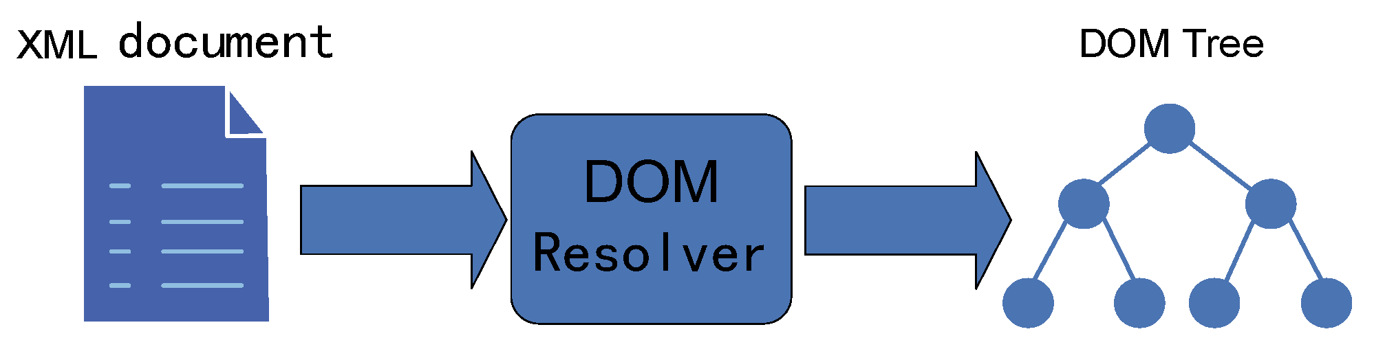
2.2. DOM Parsing of XML Documents

Following the aforementioned standard specifications, an XML document can be constructed to represent UUV command and control task elements. Upon completion of transmission, the XML document needs to be parsed to extract its data. In this study, the Document Object Model (DOM) is employed for this deconstruction process.
Initially, upon loading the XML document, the element nodes within the document are transformed into nodes within the DOM tree [40], enabling deconstruction. While this approach places certain demands on device performance and necessitates a complete pre-reading of the XML file before conversion, it offers a straightforward and efficient deconstruction method. The specific conversion process is outlined in Figure 1.

3. Mission Planning of UUV Command and Control Tasks

In this paper, the mission planning of UUV command and control tasks is subdivided into two sub-plans: temporal planning and spatial planning. The temporal planning aims to ensure that the planning of the task area is sequentially sorted to minimize the total distance traveled. The spatial planning aims to generate safe paths for the UUV, effectively avoiding obstacles.

3.1. Design of Time-Series Planning Algorithm for UUV Command and Control Tasks

As a TSP (typical Traveling Salesman Problem), this paper employs a genetic algorithm for the temporal optimization of UUV operations.
  • Encoding and population initialization
In this paper, the individuals in the genetic algorithm are defined as ‘feasible paths that traverse all task areas’. For the cities, a coding scheme of 0 to ( N 1 ) is adopted, where N represents the number of task areas to be traversed. A population of n individuals is represented by a 1 × N matrix, and a population consisting of n such individuals is stored in an N × n matrix, as shown below.
1 n 1 N p 11 p 1 n p N 1 P N n
2.
Fitness function
By selecting an origin and establishing a suitable coordinate system, each task area is represented using coordinates, facilitating the calculation of distances between any two task areas. In this paper, the total sum of distances covered by the UUV during traversal is used as a measure of fitness, where a smaller distance indicates a higher fitness. The fitness function is designed as follows:
f = 1 i = 1 N 1 x i x i 1 2 + y i y i 1 2
3.
Select operation
The selection method designed in this paper is defined based on the fitness function described earlier. If the fitness value is higher, the probability of selecting the corresponding individual will be correspondingly increased. Conversely, if the fitness value is very low, the probability of selection will be lower. The individual selection probability calculation method is as follows:
p ( i ) = f i i = 1 n f i
4.
Crossover operation
In the initial population, two chromosomes are randomly selected, and their alleles undergo crossover, resulting in the generation of new individuals that are added to the new population. This process leads to the emergence of new paths, which are then searched for potential optimal solutions.
5.
Mutation operation
Chromosomes are randomly selected from the population, and mutation operations are performed on them according to the predetermined mutation probability. In order to ensure global search optimization, this study employs a mutation operation that involves exchanging the positions of any two genes within a chromosome.
6.
Population renewal
To preserve the historical best solution and maintain a constant population size, the mutated solutions are also added to the population after the completion of the mutation operation.
7.
Termination criteria for population evolution.
A maximum number of iterations, T, is set and used as the termination condition.

3.2. Design of Spatial Path Planning Algorithm for UUV Command and Control Tasks

This paper employs an improved genetic algorithm to implement UUV spatial path planning. To avoid the premature convergence phenomenon of traditional genetic algorithms, an elitist strategy is added to the selection operation, and adaptive crossover and mutation probabilities are designed to accelerate the search speed.
  • Elitist selection strategy
The specific operation of the elitist selection strategy in this paper is as follows:
To implement the elitist selection strategy in this paper, we first find the maximum fitness value, f m a x , in the current population and calculate the average fitness value, f a v g , of the population. Given a boundary value, τ , if the maximum fitness value, f m a x , exceeds this boundary value, the elitist selection strategy is used to select the new population. Specifically, we first preserve the individual with the maximum fitness value in the population and then randomly select M individuals from the initial population. Among these M individuals, we select the one with the highest fitness value and preserve it for the next generation. We repeat this step until a new population is generated. If there are no super individuals in the population, a selection method is used to generate a new population. This paper sets τ = 2 f a v g and M = 5 .
2.
Adaptive crossover and mutation probabilities
In this paper, an adaptive design is used according to the following expectations: chromosomes with higher fitness are more likely to undergo crossover and mutations with smaller chromosomes, while chromosomes with lower fitness are more likely to undergo crossover and mutations with larger chromosomes. The following probabilities are given to adaptively design the crossover and mutation probabilities:
P c = P c 1 + P c 2 2 P c 1 P c 2 2 sin ( f f a v g f m a x f a v g × π 2 ) , f f a v g p c 1 , f < f a v g
P m = P m 1 + P m 2 2 P m 1 P m 2 2 sin ( f f a ν g f m a x f a ν g × π 2 ) , f f a ν g P m 1 , f < f a n g
Here, P c represents the crossover probability, and P m represents the mutation probability. P c 1 = 0.2 is the upper limit of the crossover probability, P c 2 = 0.01 is the lower limit of the crossover probability, P m 1 = 0.2 is the upper limit of the mutation probability, and P m 2 = 0.01 is the lower limit of the mutation probability. f m a x represents the maximum fitness value in the population, f a v g represents the average fitness value of the population, f is the fitness value of the individual to be mutated, and f is the fitness value of the individual with the minimum fitness value in the population after crossover.
3.
Constraints and optimization objectives.
We define a randomly generated path: R = ( P 0 , P 1 , P 2 , , P n ) . Among the points, P 0 represents the starting point of the path, P n denotes the destination point of the path, and the discrete points along the path are represented by n + 1 . The position of P i is represented by ( x i , y i ) .
In UUV spatial planning, the main constraint for the UUV is the safety distance and self-speed constraints for other objects except itself, while the optimization objectives are energy consumption, E(R), and path length, D(R).
The path length, D(R), is defined as follows:
D R = i = 1 n ( x i x i 1 ) 2 + ( y i y i 1 ) 2
In this paper, the influence of ocean currents on the UUV’s energy consumption is considered. A strategy is adopted to keep the ground speed fixed, and the UUV adjusts its water speed and direction in real time according to the following formula:
V = V G y V h sin ψ h 2 + V G x V h cos ψ h 2
Here, V G x represents the northward velocity of the UUV’s ground speed, V G y represents the eastward velocity of the ground speed, V h denotes the velocity of the ocean current, and ψ h represents the angle between the UUV’s heading direction and the northward direction.
The energy consumption, E(R), is defined based on the corresponding velocity as follows:
E R = i = 1 n 1 γ i j ( Γ V h cos α + V G ( i 1 i ) cos β ) D i j
In Equation (8): j = i 1 , n 1 represents the number of discrete path points. γ ij denotes the ocean current’s influence factor between two discrete path points, which is designed based on the angle between the ocean current direction and the UUV’s navigation direction. Γ represents a positive or negative sign, which is determined by the relationship between the UUV’s heading direction and the ocean current’s direction. When they are in the same direction, it is negative and generates a positive impact; when they are in opposite directions, it is positive and generates a negative impact. V h represents the velocity of the ocean current; the angle α denotes the angle between the direction from i to j and the direction of the ocean current; V G ( i 1 i ) denotes the ground speed along the i direction; and β represents the turning angle at path point i . D i j represents the path length along the direction from i to j . The following is the definition of γ i j :
γ i j = 2 0 ° < θ 30 ° 4 30 ° < θ 60 °   or   120 ° < θ 150 ° 5 60 ° < θ 120 ° 6 150 ° < θ 180 °
In Equation (9), the influence factor varies based on the different angles between the ocean current’s direction and the UUV’s heading direction.
4.
The fitness value and the degree of constraint violation
Here, we denote the objective functions of path R 1 and path R 2 as F ( R 1 ) and F ( R 2 ) , respectively.
F ( R 1 ) = F ( D ( R 1 ) E ( R 1 ) )
F ( R 2 ) = F ( D ( R 2 ) E ( R 2 ) )
If the following conditions are satisfied, it indicates that path R 1 is superior to path R 2 :
  • X { D , E } satisfies the condition min ( X ( R 1 ) ) min ( X ( R 2 ) ) , and X denotes the function D , E .
  • X { D , E } satisfies the condition min ( X ( R 1 ) ) min ( X ( R 2 ) ) .
The fitness value is defined as follows: s t r ( R i ) represents the number of individuals in the population that are inferior to the individual R i , and it is referred to as the fitness value of the individual R i .
The optimal path is the path with the highest fitness value among the feasible paths.
The degree of constraint violation is determined by the ratio of feasible paths to infeasible paths in the planning result. The formula defining the degree of constraint violation is as follows:
C ( R i ) = 1 s M = 1 s C M ( R i )
In the formula, S represents the number of constraint conditions, and C M ( R i ) represents the degree to which path R i violates the constraint condition M.
Under the constraint conditions, path R 1 is superior to path R 2 , satisfying one of the following conditions:
  • R 1 is feasible, while R 2 is infeasible;
  • Both R 1 and R 2 are feasible, but R 1 has a higher fitness value than R 2 ;
  • Both R 1 and R 2 are infeasible, but the degree of constraint violation for R 1 is lower than that of R 2 .
5.
Path encoding and initial population generation
The line segment L is obtained by connecting the starting point and the target point. L is then divided into n equal parts, marked as x i ( i = 1 , 2 , 3 , , n 1 ) . A perpendicular line, l i , is drawn through each point, x i , and a random point, p i , is selected on the line l i . This generates n − 1 path points, resulting in a randomly generated path represented as p 0 (starting point) and p 1 , p 2 , p n (target point). This simplifies the complex two-dimensional encoding method into a one-dimensional encoding method. Each path represents an individual in the population, and repeating the above method generates the required population.
The overall algorithm flow is as follows:
Step 1:
Perform population initialization to generate the required population size while setting the population size to t = 0.
Step 2:
Calculate the fitness value and degree of constraint violation for each individual in the population.
Step 3:
Select m individuals arbitrarily from the initial population as the parental population.
Step 4:
Based on the fitness values obtained in Step 2, choose n individuals from the parental population as the offspring path individuals.
Step 5:
With a certain probability, select k infeasible paths from the parental population to be added to the offspring population.
Step 6:
Among the selected n + k individuals, randomly choose two individuals. One individual is replaced by the one with the highest fitness value from the n individuals, and the other individual is replaced by the one with the least degree of constraint violation from the remaining n − 1 individuals.
Step 7:
Repeat Steps 3 to 5 until P s offspring individuals are generated.
Step 8:
With a certain probability, perform crossover and mutation operations on the offspring population generated in the previous step, and the resulting new individuals become the new generation of the population, while t = t + 1.
Step 9:
If the maximum number of iterations is reached, terminate the algorithm and output the optimal solution. If the maximum number of iterations is not reached, repeat Steps 2 to 8 until the algorithm terminates.

4. UUV Mission Re-Planning Method for Task Allocation

During its underwater operations, an UUV may encounter various uncertain events that can affect its task execution. In such cases, it is necessary to adjust or re-plan the task based on the mission, environment, and UUV’s own situation. Re-planning is a dynamic function of the mission planning system that can update the variables (target point, speed, heading, etc.) of the UUV, analyze the type of event, and provide a method of handling it [41]. This chapter analyzes the uncertainty of tasks, classifies uncertain events and their impacts, designs a detection and identification interface for re-planning events, proposes methods for handling uncertain events, describes the algorithmic process for re-planning, and considers the intervention of the commander to achieve task re-planning.

4.1. Uncertainty Analysis of UUV Operations

Uncertain factors can be divided into three categories:
  • Uncertainty about the marine environment;
  • Uncertainty about the UUV’s own state;
  • Uncertainty about unexpected events such as task execution or commander intervention.
By subdividing the above three categories and making predictions and impact analyses for different events, it is possible to provide references for triggering re-planning events and developing handling methods. The classification of events is shown in Table 1.
Based on the aforementioned detection information, the following situations are subject to detection:
  • A significant deviation between task execution and planning.
  • Real-time monitoring of UUV information reveals anomalies.
  • Changes in the UUV task environment.
In light of the aforementioned classification of uncertainty events and the analysis of their impact, appropriate measures are taken to address these events. The urgency of handling different events varies, leading to the determination of their respective priority levels.
During the execution of UUV tasks, task information, environment information, and status information should be detected; the event type should be determined; and thereby, re-planning trigger conditions should be generated. Then, a Bayesian analysis can be used to infer the degree of impact of the events. Based on the classification and impact analyses of uncertain events mentioned earlier, the events should be numbered and the degree of impact formatted in an organized manner. Different events also require different levels of urgency in terms of handling; thereby, certain events should be prioritized. Table 2 provides the detection data for the events.

4.2. Task Re-Planning Handling for Uncertain Events

Based on the aforementioned analysis of the impact of events, the following conclusions can be drawn regarding the handling of corresponding uncertainty events:
  • Uncertain appearance of obstacles
The appearance of unknown obstacles has a significant impact on UUV missions. In such cases, it is necessary to update the mission information, environmental information, and status information of the UUV. The global planning algorithm is invoked to perform mission re-planning in order to achieve better mission completion.
  • Deviation from the planned route: critical point unreachable:
When the UUV deviates from the planned route during mission execution, the commander issues instructions to adjust the UUV’s angle and speed. If the problem persists, the spatial planning algorithm is used for re-planning. If the issue remains unresolved, the global planning algorithm is invoked to re-plan the UUV mission.
  • Key point unreachable:
In the event of unreachable key points, the spatial path planning algorithm is invoked for re-planning. If it is found that spatial path re-planning fails to achieve global optimality, the global planning algorithm is used for re-planning.
  • Task parameter change:
In the case of task parameter changes, corresponding adjustments are made based on the task requirements and state conditions to complete global re-planning. Additionally, the commander supervises the UUV’s task execution and, based on the current task status, manually intervenes in the UUV’s task parameters. The commander can issue commands by writing an XML task document, invoking the global planning algorithm, and conveying the re-planning results to the UUV to facilitate subsequent tasks.
  • Task type change:
When the task type changes, the task information needs to be updated, and global re-planning is required to complete the subsequent tasks.
  • Energy shortage:
In the event of an energy shortage, if the task is almost complete, the operating speed can be appropriately accelerated to complete the task before the energy is depleted. If there are multiple pending tasks and an energy shortage occurs, they should be re-planned according to priority as constraints. When the energy shortage is severe, the commander orders the suspension of the task and for the UUV to float up to the water surface to wait for rescue.
  • Time window change:
When the time window changes, the UUV needs to perform global re-planning based on the actual task situation and status to ensure the successful completion of the task.
  • Propeller malfunction:
When the propeller fails, the next step of planning needs to be made based on the specific degree of the propeller failure and the current task requirements. If the impact is not significant, subsequent tasks can be performed first, and the repair can be carried out after the tasks are completed. If the failure affects the stability of the UUV, global re-planning is required to continue the mission. If the propeller has caused a significant impact on the UUV’s normal operation, subsequent tasks should be abandoned, and the commander should order the UUV to float up to the water surface and wait for rescue.
  • Navigation failure:
When a navigation failure event occurs during the UUV mission, the commander may issue instructions, in the absence of any immediate danger, based on the completion status of the mission and the requirements of subsequent tasks. These instructions will cause the UUV to ascend to an appropriate depth for navigation failure, and after updating the relevant information, the UUV can resume the mission.

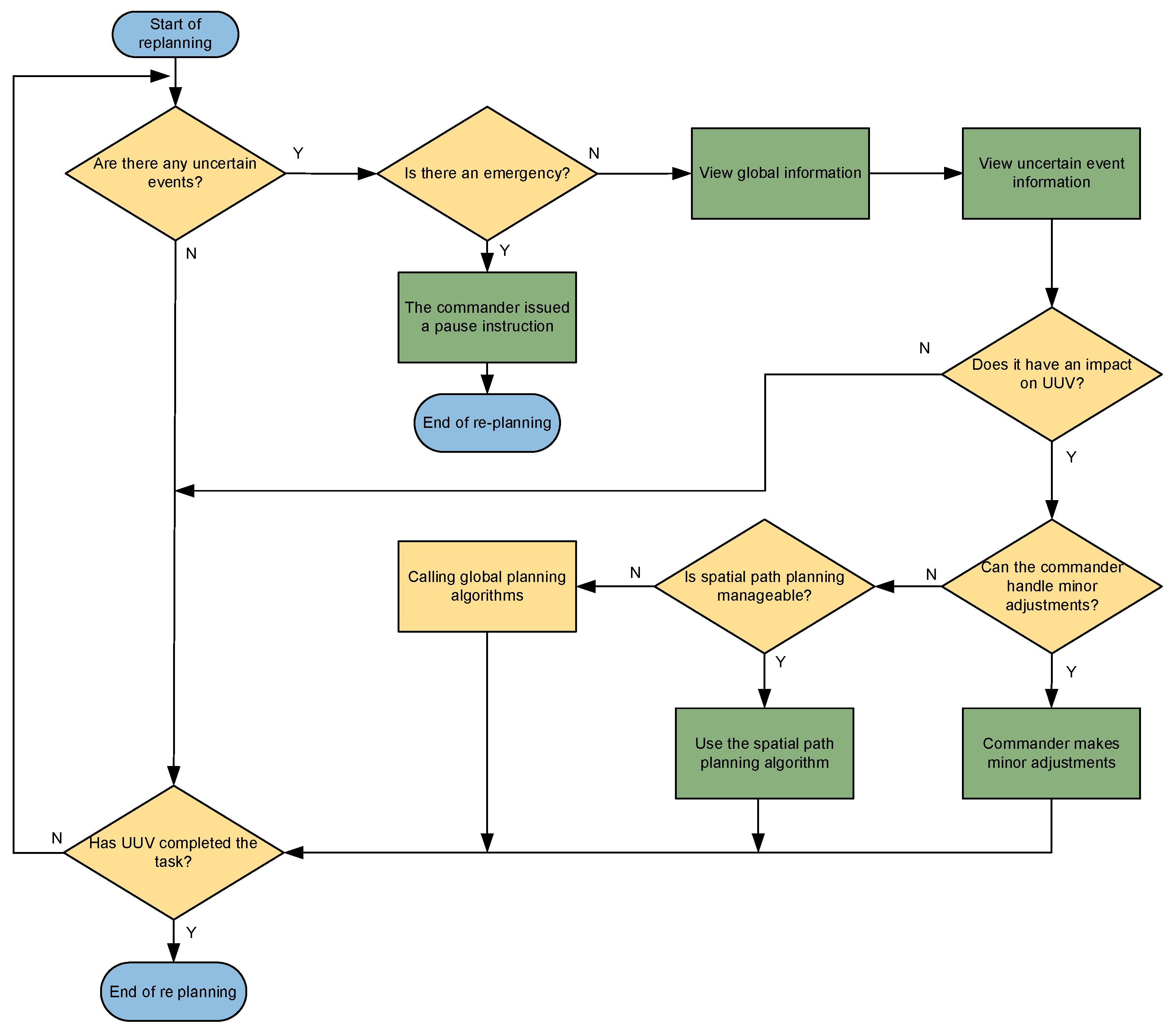
4.3. Design of Re-Planning Process for Command and Control Tasks

Based on the above analysis of uncertain events, the algorithmic process and specific steps for UUV mission re-planning are described in Figure 2.
  • Initiate UUV task re-planning and set relevant parameters.
  • Detect if an uncertain event has occurred. If yes, go to step 3. If not, go to step 13.
  • Determine if it is an emergency-triggering event. If yes, go to step 12 for special handling to ensure UUV safety. If not, go to step 4.
  • Review global information, including the environment, task, and UUV status.
  • Further review uncertain event information based on global and UUV information.
  • Assess the event’s impact on the UUV’s task. If there is no impact, go to step 13. If there is an impact, go to step 7.
  • Determine if the commander’s parameter adjustments can handle the event. If yes, go to step 8. If not, go to step 9.
  • The commander adjusts the initial plan’s parameters. Go to step 13.
  • Assess if spatial re-planning can handle the event. If yes, go to step 10. If not, go to step 11.
  • Perform spatial re-planning based on event and global information. Go to step 13.
  • Perform full task re-planning based on event and global information. Go to step 13.
  • The event requires special handling to ensure UUV safety as re-planning cannot resolve it. The commander issues an abandon task and surface for rescue order. End re-planning.
  • Check if the UUV completed the task. If yes, go to step 14. If not, go back to step 2 until no further re-planning is needed and the UUV completes the task successfully.
  • Task re-planning completed. Overall UUV task completed.

5. Results

5.1. Simulation Procedure of UUV Control Task Re-Planning with Human in the Loop

Below are the general steps involved in the simulation of UUV control task re-planning:
  • Firstly, the parameter setting needs to be completed. The commander sets the parameters required for the optimization algorithm, including the population size, the number of iterations, the crossover probability, and the mutation probability.
  • The commander sets the parameters for the UUV, task area, and obstacles based on the mission requirements.
  • After completing the configuration of the UUV mission parameters, the tasks to be performed by the UUV are planned. This includes determining the execution time sequence for various task areas, seeking the shortest and least energy-consuming paths, and displaying the planning information in the task planning results section.
  • After the completion of the UUV mission execution, the UUV will execute the planned tasks according to the generated plan.
  • In the event that the commander triggers an uncertainty event during the execution of the UUV control planning, the UUV must make further planning decisions based on the type of event, its impact level, and the appropriate event handling methods. If the uncertainty event does not affect the UUV’s ability to continue executing the mission, it may proceed with the initial planned trajectory. However, if the event impacts the UUV’s ability to continue the mission, it is imperative for the UUV to pause the execution of the tasks, conduct a situational analysis, and invoke either a re-planning algorithm or seek input from the commander for adjustments. Subsequently, the UUV resumes the mission based on the revised plan. If no uncertainty events are encountered during the mission, the UUV proceeds directly to the next step.
  • The UUV executes the mission according to the planned trajectory and returns to the designated recovery point upon completion, marking the successful accomplishment of the mission.

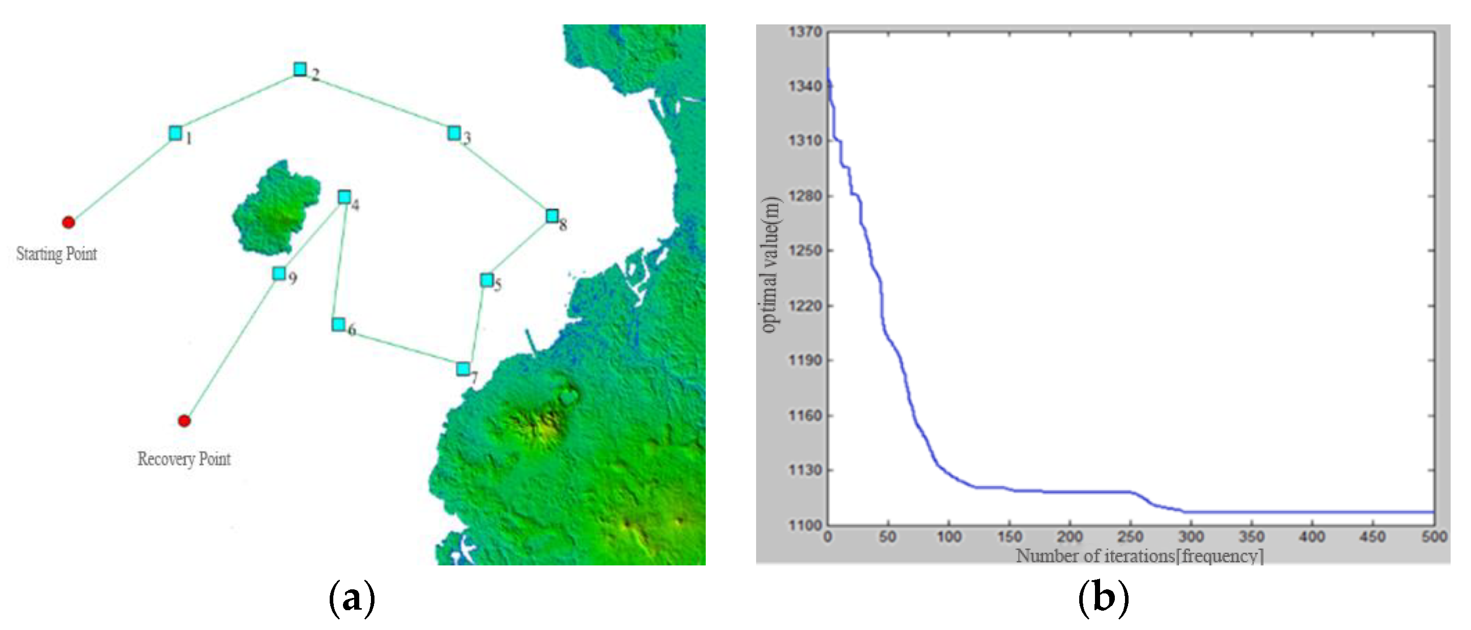
5.2. Simulation Procedure of Time-Series Planning Algorithm for UUV Command and Control Tasks

In Section 3 of this paper, a genetic algorithm-based UUV temporal sequence algorithm design is proposed. In order to validate its feasibility and effectiveness, the following section presents a simulation verification of this approach.
Within the simulation interface in Figure 3a, the UUV is represented as a particle. The task area is depicted as a blue rectangular region, while the recovery point is represented as a point. The green area represents the presence of terrain obstacles.
The parameter settings for the temporal sequence planning simulation are as follows. Within the UUV mission environment, the commander configures nine distinct task areas, as well as deployment and recovery points for the UUV, thereby establishing the conditions for the simulation tasks. The genetic algorithm’s parameter settings are as follows: a population size of N = 500, termination generation at T = 500, the crossover probability set to p c = 0.8 , and the mutation probability defined as p m = 0.1 . Figure 3 illustrates the optimized generated path and the iterative optimization curve.
The displayed results demonstrate that the algorithm designed in this paper exhibits rapid convergence, effectively addressing the challenges associated with temporal planning for UUVs.

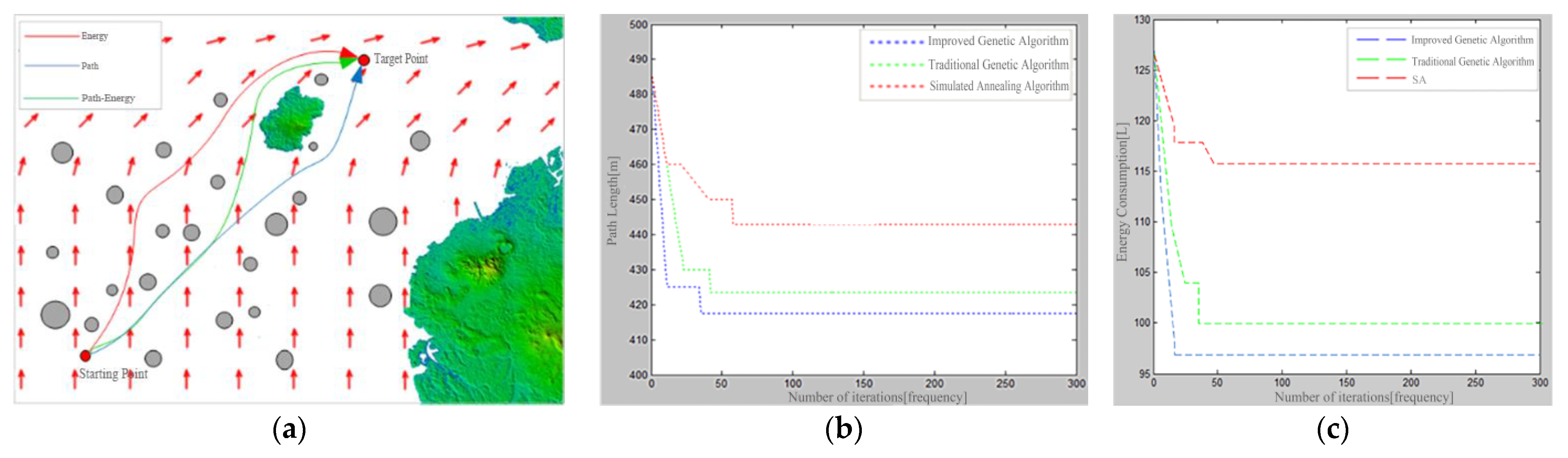
5.3. Simulation Procedure of Spatial Path Planning Algorithm for UUV Command and Control Tasks

The spatial planning for a UUV control task refers to the global path planning of the UUV, which plays a crucial role in the execution of these missions. The effectiveness of spatial path planning significantly influences the successful completion of UUV tasks. This paper proposes a global path planning approach based on an improved genetic algorithm. The following section presents a simulation experiment for spatial path planning.
Figure 4 shows the simulation results of spatial path planning for the UUV control task, the iterative optimization curve of the spatial path planning algorithm, and the iterative optimization curve of the energy consumption during spatial path planning.
In Figure 4a, the arrows represent ocean currents, with the size and direction of the arrows corresponding to the magnitude and direction of the current at each point. The three curves in different colors in the figure, respectively, represent the spatial path planning results of the genetic algorithm, the improved genetic algorithm, and a simulated annealing algorithm for optimizing UUV energy consumption and path length. At this point, the cost function of the path is defined as the path length and energy consumption of the UUV throughout the trajectory. It can be observed from the figure that all three algorithms can effectively utilize the effect of ocean currents, with the improved genetic algorithm performing particularly well in leveraging the effect of ocean currents. This leads to not only reduced energy consumption in the UUV but also shorter path lengths.
In Figure 4b,c, the iterative curves of the path and energy consumption clearly demonstrate the comparative results of optimization capabilities between the genetic algorithm, the improved genetic algorithm, and the simulated annealing algorithm. Furthermore, Table 3 provides a tabulated representation of the planning results for each algorithm depicted in Figure 4b, revealing that the improved genetic algorithm outperforms the other two algorithms in terms of its optimization capability. Not only does it converge faster towards the optimal solution, but it also achieves a more desirable optimal value. Through a comprehensive analysis, it can be concluded that the improved genetic algorithm exhibits significant advantages over the other algorithms in addressing spatial path planning problems.

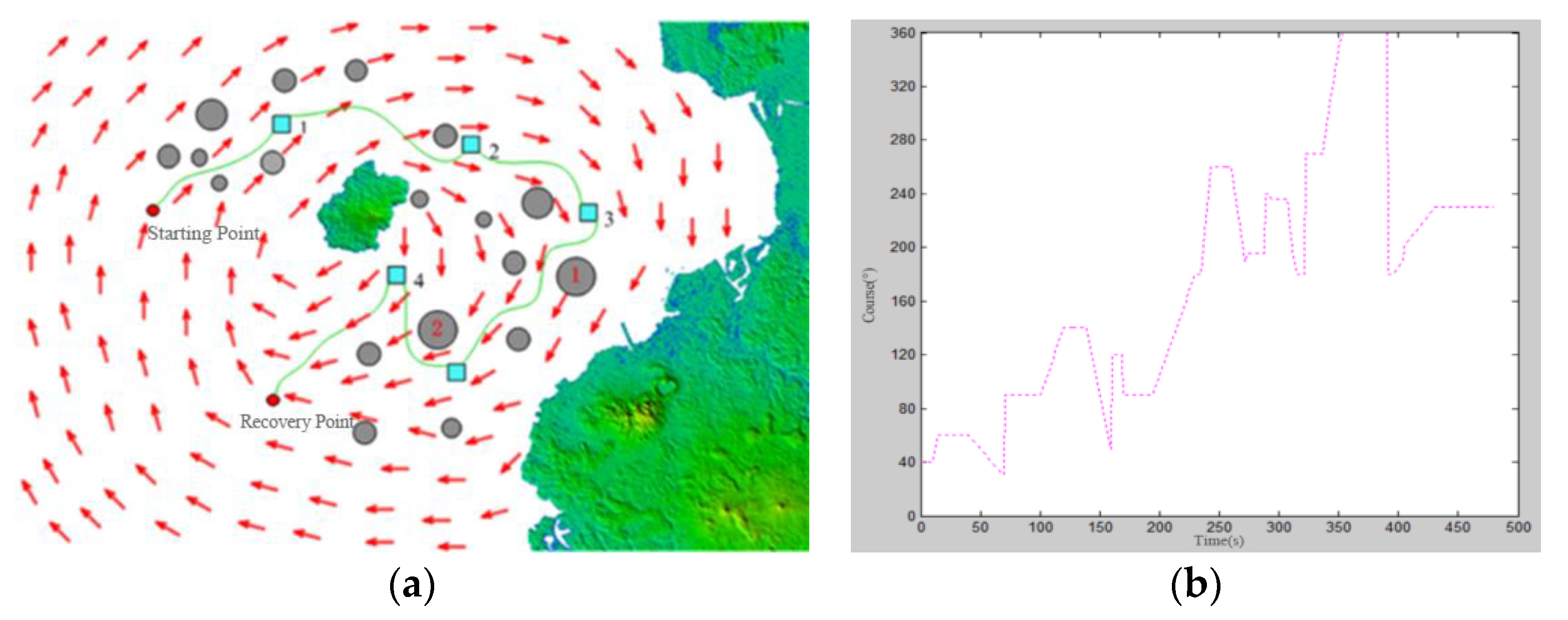
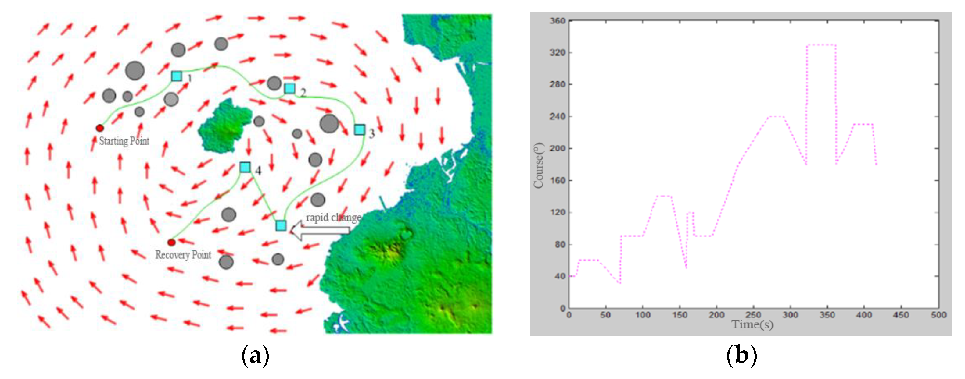
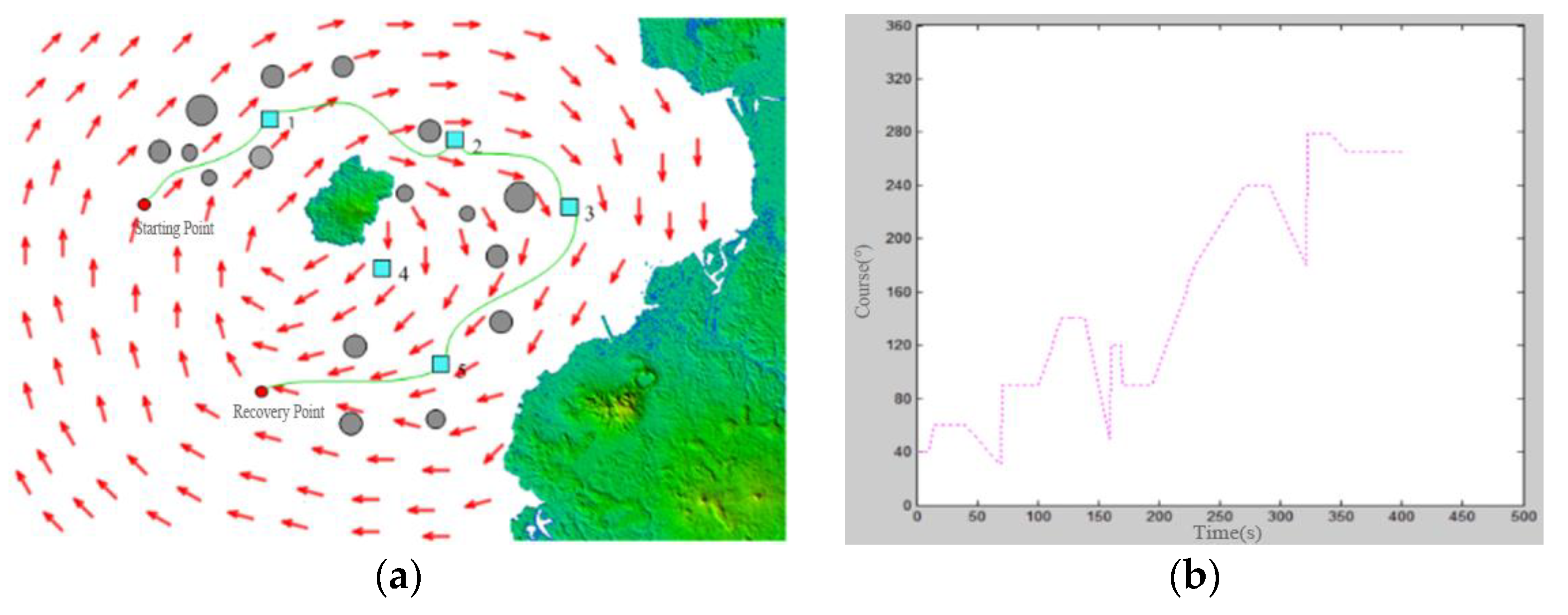
5.4. Simulation of UUV Control and Command Task Re-Planning under Uncertain Events

The steps of the simulation experiment for control task re-planning are as follows: The UUV executes the initial mission plan for the assigned task. During the task execution, the uncertain event button is triggered, and the UUV performs the corresponding re-planning based on the type and impact level of the event. Subsequently, the UUV continues to execute the mission according to the re-planning scheme. This simulation aims to provide verification for uncertain events based on the categories of marine environmental uncertainties, task execution and commander intervention uncertainties, and self-state uncertainties.
  • Marine environmental events: Uncertain appearance of obstacles
During the execution of tasks in the marine environment, there is always a possibility of encountering obstacles that were not present during the initial planning phase. When an obstacle appears, it is necessary to promptly re-plan the mission in order to ensure the UUV’s safety and maximize task completion. The simulation of this scenario is as follows:
As evident from Figure 5a, the appearance of obstacles 1 and 2 is characterized by uncertainty, as they were not initially considered during the planning phase. When a UUV detects the presence of an obstacle while executing a mission, it invokes a spatial path planning algorithm to handle the uncertain occurrence of obstacles. The UUV then proceeds to execute the mission based on the results of re-planning, ultimately returning successfully to the recovery point. Figure 5b depicts the motion direction of the UUV.
2.
Task execution events: Non-human-induced changes in task parameters
When the UUV is executing the mission according to the initial plan, there may arise a need to adjust its velocity parameter due to task requirements or time constraints. In such cases, it becomes necessary to appropriately increase the UUV’s operating speed. The simulation scenario for this situation is as follows:
Figure 6a provides a simulation validation of events involving non-human-induced changes in task parameters encountered during the UUV’s mission execution. Specifically, during the execution of the task in Region 4, the UUV’s navigation speed undergoes a modification, increasing to 1.4 times its original value. As a result, the time required for task completion is relatively reduced. Figure 6b illustrates the motion direction of the UUV in this context.
3.
Self-state events: Energy shortage
An energy shortage is a self-state uncertain event encountered by UUVs during mission execution. It arises due to inaccurate energy estimation, leading to insufficient energy levels during task execution. In such cases, the UUV necessitates invoking a re-planning method specific to UUV control tasks. The simulation results for this scenario are as follows:
Figure 7a illustrates the re-planning results for UUVs experiencing an energy shortage. Upon completing the task in Region 3, the UUV detects an energy shortage, with its remaining energy levels being sufficient only for executing one more task. As the task in Region 5 is of a higher priority than the task in Region 4, a global re-planning scheme is applied, enabling the UUV to continue with the task in Region 5 before returning to the recovery point. Figure 7b shows the motion direction of the UUV during this scenario.
The above experiment validates the effectiveness of the UUV control task re-planning method, which can further improve a UUV’s safety and task capability. This research serves as a significant contribution to UUV control tasks.

6. Conclusions

This study on human-in-the-loop unmanned underwater vehicle (UUV) control task planning, focusing on enhancing the effectiveness and accuracy of UUV mission completion, holds significant theoretical and practical value.
The summary of the entire article and the main research work and achievements are as follows:
The standardization of the UUV mission elements was accomplished through the utilization of the XML language.
To address the problem of human-in-the-loop UUV command and control task planning, we developed a time-series planning method based on a genetic algorithm and an enhanced genetic algorithm for spatial path planning.
We analyzed and classified uncertain events, determining their priority order, and developed a re-planning approach for UUV control tasks.
Then, we designed simulation software for UUV control task planning and re-planning based on QT. The software integrates time-series planning, spatial path planning, and UUV task re-planning on the simulation experimental platform.
Time-series planning, based on a genetic algorithm, effectively reduces the path length. Improved genetic-algorithm-based spatial path planning effectively avoids obstacles and minimizes energy consumption. The control task re-planning method aids in UUV control task planning, enabling smoother task completion.
However, the marine environment poses unique challenges, including potential uncertainties such as complex and dynamic obstacles. Further research should focus on quantifying this working environment.
In summary, this study on human-in-the-loop unmanned underwater vehicle (UUV) control task planning presents valuable contributions to enhancing the effectiveness and accuracy of UUV mission completion. This study’s significant contributions lie in accomplishing the standardization of UUV mission elements, developing time-series and enhanced genetic-algorithm-based planning methods, analyzing and addressing uncertain events, and designing simulation software for UUV control task planning and re-planning. These advancements hold both theoretical and practical value for current research on UUVs.

Author Contributions

Conceptualization, D.Y., M.H. and H.W.; methodology, J.Y., M.H. and J.W.; software, H.W., M.H., Q.Z. and J.W.; validation, J.Y., Z.W. and D.Y.; writing—original draft preparation, J.W. and Q.Z. All authors have read and agreed to the published version of the manuscript.

Funding

This research work was supported by the National Science and Technology Innovation Special Zone Project (21-163-05-ZT-002-005-03), the National Key Laboratory of Underwater Robot Technology Fund (No. JCKYS2022SXJQR-09), and a special program to guide high-level scientific research (No. 3072022QBZ0403).

Institutional Review Board Statement

Not applicable.

Informed Consent Statement

Not applicable.

Data Availability Statement

Data are contained within the article.

Conflicts of Interest

No potential conflicts of interest were reported by the authors.

References

  1. Cao, X.; Ren, L.; Sun, C. Dynamic target tracking control of autonomous underwater vehicle based on trajectory prediction. IEEE Trans. Cybern. 2022, 53, 1968–1981. [Google Scholar] [CrossRef] [PubMed]
  2. Liu, B. Recent advancements in autonomous robots and their technical analysis. Math. Probl. Eng. 2021, 2021, 6634773. [Google Scholar] [CrossRef]
  3. Zhang, W.; Wang, N.X.; Wei, S.L.; Du, X.; Yan, Z.P. Overview of unmanned underwater vehicle swarm development status and key technologies. J. Harbin Eng. Univ. 2020, 41, 289–297. [Google Scholar]
  4. Huang, H.; Zeng, Y.P. Research on Intelligent Cooperative Command and Control System of Unmanned Equipment in Amphibious Operations. In Proceedings of the International Conference on Autonomous Unmanned Systems, Xi’an, China, 23–25 September 2022; Springer Nature: Singapore, 2022; pp. 305–319. [Google Scholar]
  5. Buadu, S.; Schjølberg, I.; Mo-Bjørkelund, T. Mission planner for multiple AUVs: Verification procedures combining simulations and experiments. In Proceedings of the 2018 IEEE/OES Autonomous Underwater Vehicle Workshop (AUV), Porto, Portugal, 6–9 November 2018; IEEE: Piscataway, NJ, USA, 2018; pp. 1–6. [Google Scholar]
  6. Zuo, R.; Wang, Z.; Bastidas, C.E.C.; Gursoy, M.C.; Solomon, A.; Qiu, Q. A Predictive Control Framework for UAS Trajectory Planning Considering 4G/5G Communication Link Quality. In Proceedings of the 2023 Integrated Communication, Navigation and Surveillance Conference (ICNS), Herndon, VA, USA, 18–20 April 2023; IEEE: Piscataway, NJ, USA, 2023; pp. 1–10. [Google Scholar]
  7. Liu, C.; Liu, H. Research on key technologies of simulated training system for large ground control station of UAS. In Proceedings of the Global Intelligence Industry Conference (GIIC 2018), Beijing, China, 21–23 May 2018; SPIE: Bellingham, WA, USA, 2018; Volume 10835, pp. 382–386. [Google Scholar]
  8. Stefek, A.; Casar, J.; Stary, V.; Gacho, L. Coupling of ode and des models for simulation of air defence in war-gaming experiment. Int. J. Simul. Model. 2022, 21, 41–52. [Google Scholar] [CrossRef]
  9. Usach, H.; Vila, J.A. Reconfigurable mission plans for RPAS. Aerosp. Sci. Technol. 2020, 96, 105528. [Google Scholar] [CrossRef]
  10. Johnson, J. Automating the OODA loop in the age of intelligent machines: Reaffirming the role of humans in command-and-control decision-making in the digital age. Def. Stud. 2023, 23, 43–67. [Google Scholar] [CrossRef]
  11. Kaneshige, J.; Lombaerts, T.; Shish, K.H.; Feary, M. Command and Control Concepts for a Lift Plus Cruise Electric Vertical Takeoff and Landing Vehicle. In Proceedings of the AIAA AVIATION 2023 Forum, San Diego, CA, USA, 12–16 June 2023. [Google Scholar]
  12. Boss, L.N.; Gralla, E.L. Robustness of decentralized decision-making architectures in command and control systems. Syst. Eng. 2023, 26, 149–161. [Google Scholar] [CrossRef]
  13. Chen, B.; Pang, G.; Xiang, Z.; Tao, H.; Chen, Y. Load Allocation Strategy for Command and Control Networks based on Interdependence Strength. KSII Trans. Internet Inf. Syst. TIIS 2023, 17, 2419–2435. [Google Scholar]
  14. Jünger, F.; Schopferer, S.; Benders, S.; Dauer, J.C. Talking to Autonomous Drones: Command and Control Based on Hierarchical Task Decomposition. In Proceedings of the 2021 International Conference on Unmanned Aircraft Systems (ICUAS), Athens, Greece, 15–18 June 2021; IEEE: Piscataway, NJ, USA; pp. 968–977. [Google Scholar]
  15. Karimanzira, D.; Jacobi, M.; Pfuetzenreuter, T.; Rauschenbach, T.; Eichhorn, M.; Taubert, R.; Ament, C. First testing of an AUV mission planning and guidance system for water quality monitoring and fish behavior observation in net cage fish farming. Inf. Process. Agric. 2014, 1, 131–140. [Google Scholar] [CrossRef]
  16. Hagen, P.E. AUV/UUV mission planning and real time with the HUGN operator system. In Proceedings of the Oceans 2001 MTS/IEEE-An Ocean Odyssey, Honolulu, HI, USA, 5–8 November 2001; pp. 468–473. [Google Scholar]
  17. Cheng, F.; Gao, G.P. Research on Intelligent Technology of Submarine Command and Control System. Fire Control Command Control 2014, 39, 1–5. [Google Scholar]
  18. Fang, F.; Ma, X.; Qian, K.; Liang, Z. Architecture design for mobile robot task planning and execution system in intelligent environments. J. Southeast Univ. Nat. Sci. Ed. 2012, 42, 182–185. [Google Scholar]
  19. Hwang, N.E.; Kim, H.J.; Kim, J.G. Centralized Mission Planning for Multiple Robots Minimizing Total Mission Completion Time. Appl. Sci. 2023, 13, 3737. [Google Scholar] [CrossRef]
  20. Yao, W.; Chen, Y.; Fu, J.; Qu, D.; Wu, C.; Liu, J.; Sun, G.; Xin, L. Evolutionary utility prediction matrix-based mission planning for unmanned aerial vehicles in complex urban environments. IEEE Trans. Intell. Veh. 2022, 8, 1068–1080. [Google Scholar] [CrossRef]
  21. Zhang, J.; Cui, Y.; Ren, J. Dynamic mission planning algorithm for UAV formation in battlefield environment. IEEE Trans. Aerosp. Electron. Syst. 2022, 59, 3750–3765. [Google Scholar] [CrossRef]
  22. Brown, H.C.; Sloat, J.V. The Application of Computational Geometry for Automated UUV Mission Planning. In Proceedings of the OCEANS 2022, Hampton Roads, VA, USA, 17–20 October 2022; IEEE: Piscataway, NJ, USA, 2022; pp. 1–7. [Google Scholar]
  23. Lindsay, J.; Ross, J.; Seto, M.L.; Gregson, E.; Moore, A.; Patel, J.; Bauer, R. Collaboration of heterogeneous marine robots toward multidomain sensing and situational awareness on partially submerged targets. IEEE J. Ocean. Eng. 2022, 47, 880–894. [Google Scholar] [CrossRef]
  24. Transeth, A.A.; Schjølberg, I.; Lekkas, A.M.; Risholm, P.; Mohammed, A.; Skaldebø, M.; Haugaløkken, B.O.; Bjerkeng, M.; Tsiourva, M.; Py, F. Autonomous subsea intervention (SEAVENTION). IFAC-PapersOnLine 2022, 55, 387–394. [Google Scholar] [CrossRef]
  25. Mahmoudzadeh, S.; Powers, D.M.W.; Atyabi, A. UUV’s hierarchical DE-based motion planning in a semi dynamic underwater wireless sensor network. IEEE Trans. Cybern. 2018, 49, 2992–3005. [Google Scholar] [CrossRef]
  26. Al-Khatib, H.; Antonelli, G.; Caffaz, A.; Caiti, A.; Casalino, G.; de Jong, I.B.; Duarte, H.; Indiveri, G.; Jesus, S.; Kebkal, K.; et al. The widely scalable Mobile Underwater Sonar Technology (WiMUST) project: An overview. In Proceedings of the OCEANS 2015, Genova, Italy, 18–21 May 2015; pp. 1–5. [Google Scholar]
  27. Di Lillo, P.; Di Vito, D.; Simetti, E.; Casalino, G.; Antonelli, G. Satellite-Based Tele-Operation of an Underwater Vehicle-Manipulator System. Preliminary Experimental Results. In Proceedings of the 2018 IEEE International Conference on Robotics and Automation (ICRA), Brisbane, QLD, Australia, 21–25 May 2018; pp. 7504–7509. [Google Scholar]
  28. Simetti, E.; Casalino, G.; Torelli, S.; Sperinde, A.; Turetta, A. Floating underwater manipulation: Developed control methodology and experimental validation within the trident project. J. Field Robot. 2014, 31, 364–385. [Google Scholar] [CrossRef]
  29. Cheng, S.; Wang, H.; Huang, S.; Chen, Y.; He, C.; Niu, S. Research on Coordinated Task Planning Method of Large-Scale Regional Search and Exploration for UUV and USV. In Proceedings of the 2023 42nd Chinese Control Conference (CCC), Tianjin, China, 24–26 July 2023; IEEE: Piscataway, NJ, USA, 2023; pp. 2086–2091. [Google Scholar]
  30. Zou, H.; Bian, X.Q. DEDS Modelling and Simulation of the Planning of AUV Control System. Comput. Simul. 2007, 24, 164–167. [Google Scholar]
  31. Zou, H.; Bian, X.Q.; Xiong, H.S. Research on the Misson and Task Coordination Method of AUV Control System at Planning Layer. Robot 2006, 28, 651–655. [Google Scholar]
  32. Zhang, R.B.; Liu, H.T. Research on Mission Planning and Re-Planning for AUV; Harbin Engineering University: Harbin, China, 2013. [Google Scholar]
  33. Zhang, R.B.; Tong, H.B.; Shi, C.T.; Liu, H.T. Research on autonomous underwater vehicle hierarchical mission planning and re-planning in uncertain environment. J. Nanjing Univ. Nat. Sci. 2015, 51, 148–156. [Google Scholar]
  34. Yan, J.; Zhu, Y.; Zhao, J.; Cai, H. Task Planner Design Based on Petri Net for Multi-robot Teleoperation over Internet. In Proceedings of the 2006 IEEE/RSJ International Conference on Intelligent Robots and Systems, Beijing, China, 9–15 October 2006. [Google Scholar]
  35. Shi, Y.K.; Gao, X.G. Application of Hierarchical Task Network Planning to Uninhabited Combat Aerial Vehicles Planning. Fire Control Command Control 2007, 1, 11–13. [Google Scholar]
  36. Feng, Y.; Shi, W.; Shi, W.; Cheng, G.; Huang, J. Benchmarking framework for command and control mission planning under uncertain environment. Soft Comput. 2020, 24, 2463–2478. [Google Scholar] [CrossRef]
  37. Zhang, Y.-J.; Mu, X.-D.; Liu, X.-W.; Wang, X.-Y.; Dong, C.; Wu, T.-Y.; Li, K. Application of quantum approximate optimization algorithm to mission planning of command and control organization. Acta Phys. Sin. 2021, 70, 230304. [Google Scholar] [CrossRef]
  38. Ma, S.; Lu, J. An Adaptive Mission Planning Method for UUV Combat Operations Under Uncertain Conditions. In Proceedings of the 2019 IEEE International Conference on Unmanned Systems (ICUS), Beijing, China, 17–19 October 2019; IEEE: Piscataway, NJ, USA, 2019; pp. 831–836. [Google Scholar]
  39. Zhang, L.; Xu, T.; Li, W.B. The Design Method of Naval Operation Simulation Scenario based on XML. Fire Control Command Control 2010, 35, 73–76. [Google Scholar]
  40. Choi, H.; Sim, S. A study on efficiency of markup language using DOM tree. Wirel. Pers. Commun. 2016, 86, 143–163. [Google Scholar] [CrossRef]
  41. Mou, S.; Bu, H.; Zhang, J.; Luo, Y. Re-planning method for space station pop-up missions. Acta Aeronaut. Astronaut. Sin. 2017, 38, 271–278. [Google Scholar]
Figure 1. The conversion diagram.
Jmse 12 00420 g001
Figure 2. Algorithm flow for reprogramming UUV command and control tasks.
Jmse 12 00420 g002
Figure 3. The optimized path (a) and the iterative optimization curve (b).
Jmse 12 00420 g003
Figure 4. The simulation results of spatial path planning for the UUV command and control task (a), the iterative optimization curve (b), and the energy consumption iteration curve (c).
Jmse 12 00420 g004
Figure 5. Re-planning for uncertain appearance of obstacles (a) and motion direction of the UUV (b).
Jmse 12 00420 g005
Figure 6. Changes in operating speed parameter (a) and motion direction of the UUV (b).
Jmse 12 00420 g006
Figure 7. The re-planning results for UUVs experiencing an energy shortage (a) and the motion direction of the UUV (b).
Jmse 12 00420 g007
Table 1. Classification of uncertain events and their impacts.
Event TypeEvent NameEvent Impact
Uncertain events related to the marine environment.Uncertain appearance of obstaclesThe uncertain appearance of obstacles threatens the safety of the UUV
Deviation from the planned routeThis can lead to excessive energy consumption, a waste of time, and even mission failure
Key point unreachableThis can result in a deadlock or have an impact on the safety of the UUV
Uncertain events related to commander interventionTask parameter changeThe planned task cannot be carried out properly
Task type changeThe planned task cannot be carried out properly
Uncertain events related to the UUV’s own state.Energy shortageThe remaining energy may not be sufficient to complete subsequent tasks, or certain tasks may need to be prioritized or sacrificed
Time window changeThe task cannot be completed on time according to the original plan
Propeller malfunctionThe inability to continue task execution poses a threat to self-safety
Navigation failureThe inability to obtain accurate location information
Table 2. Detection data for uncertain events.
Event TypeEvent NameEvent NumberImpact LevelPriority
Uncertain events related to the marine environment.Uncertain appearance of obstacles10–29
Deviation from the planned route20–27
Key point unreachable30–28
Uncertain events related to commander interventionTask parameter change40–210
Task type change50–210
Uncertain events related to the UUV’s own state.Energy shortage60–29
Time window change70–27
Propeller malfunction80–28
Navigation failure90–26
Table 3. Algorithm comparison.
Path Length (m)Energy Consumption (L)Time
(s)
Number of Iterations (Generation)
Simulated annealing algorithm445.6120.4235.3300
Traditional genetic algorithm424.3102.8206.5300
Improved genetic algorithm418.597.2198.0300
Disclaimer/Publisher’s Note: The statements, opinions and data contained in all publications are solely those of the individual author(s) and contributor(s) and not of MDPI and/or the editor(s). MDPI and/or the editor(s) disclaim responsibility for any injury to people or property resulting from any ideas, methods, instructions or products referred to in the content.

