
Development of Representative Sailing Mode Construction Methodology Using Markov Chain


Abstract
1. Introduction
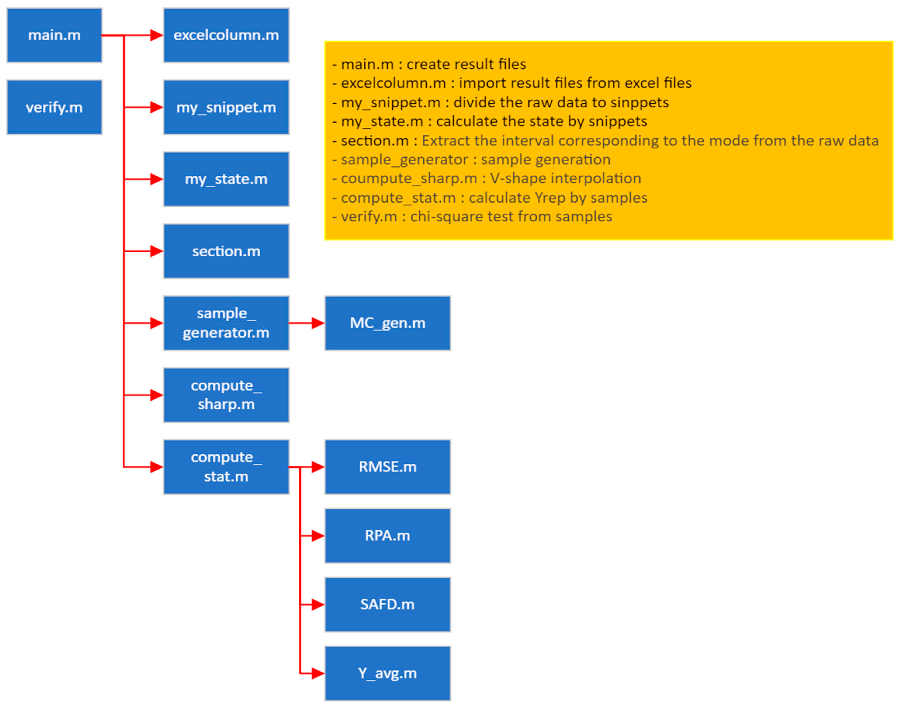
2. Methodology
3. Selection of the Target for Generating the Representative Sailing Mode
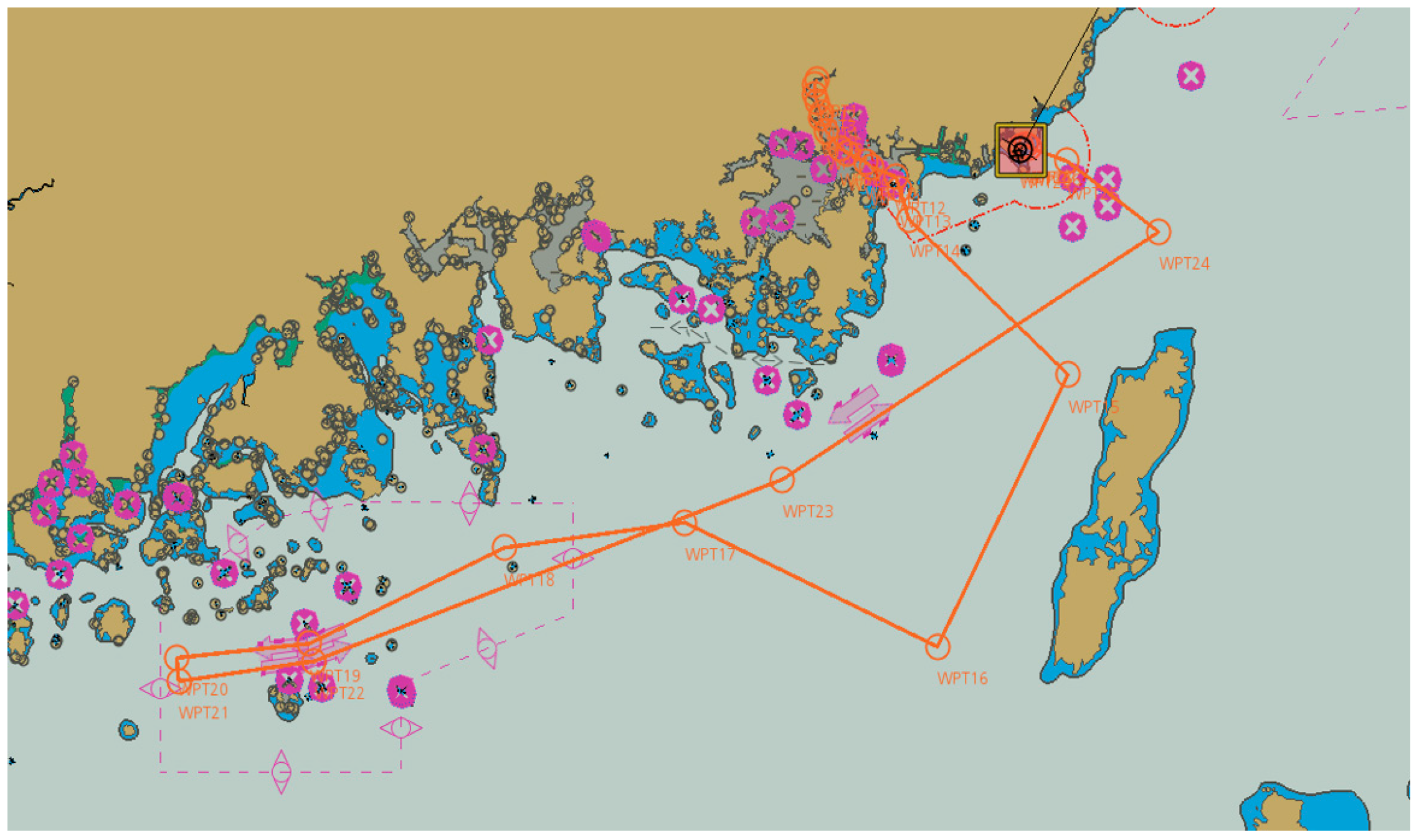
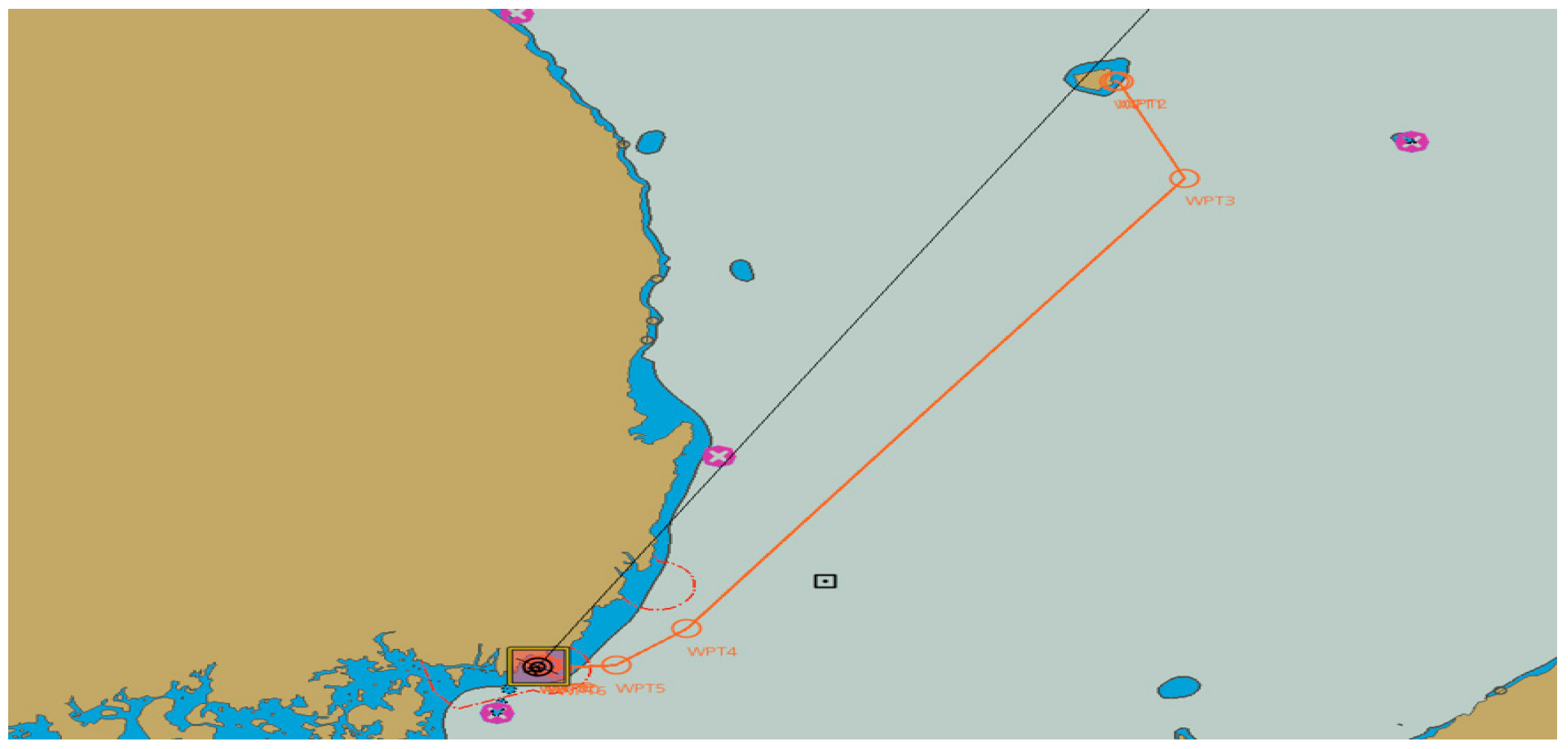
3.1. Target Ship and Voyages
3.2. Prerequisites for the Generation of the Representative Sailing Mode
4. Results
5. Conclusions
Author Contributions
Funding
Institutional Review Board Statement
Informed Consent Statement
Data Availability Statement
Conflicts of Interest
References
- Tokuşlu, A. Analyzing the Energy Efficiency Design Index (EEDI) Performance of a Container Ship. Int. J. Environ. Geoinf. 2020, 7, 114–119. [Google Scholar] [CrossRef]
- IMO. MEPC 80 highlights. In Proceedings of the 80th Session of the Marine Environment Protection Committee, MEPC 80, London, UK, 3–7 July 2023. [Google Scholar]
- MEPC. Guidelines on the Method of Calculation of the Attained Energy Efficiency Design Index (EEDI) for New Ships; Circ: Danville, VA, USA, 2012; Volume 212, p. 1. [Google Scholar]
- MEPC 59/Circ. 684. Guidelines for Voluntary Use of the Ship Energy Efficiency Operational Indicator (EEDI); IMO: London, UK, 2009.
- Ivanova, G. Analysis of the Specifics in Calculating the Index of Existing Marine Energy Efficiency EEXI in Force Since 2023. In Proceedings of the 13th Electrical Engineering Faculty Conference (BulEF), Varna, Bulgaria, 8–11 September 2021; Volume 2021, pp. 1–4. [Google Scholar] [CrossRef]
- Introduction of EEXI, Korean Register. Available online: https://www.krs.co.kr/kor/Content/CF_View.aspx?MRID=234&URID=72 (accessed on 11 January 2023).
- Baldi, F.; Ahlgren, F.; Melino, F.; Gabrielii, C.; Andersson, K. Optimal load allocation of complex ship power plants. Energy Convers. Manag. 2016, 124, 344–356. [Google Scholar] [CrossRef]
- Burt, C.M.; Piao, X.; Gaudi, F.; Busch, B.; Taufik, N.F. Electric motor efficiency under variable frequencies and loads. J. Irrig. Drain. Eng. 2008, 134, 129–136. [Google Scholar] [CrossRef]
- IEA (International Energy Agency). Fuel Efficiency Labelling System. Available online: https://www.iea.org/policies/980-fuel-efficiency-labelling-system (accessed on 2 March 2023).
- EPA (United States Environmental Protection Agency). EPA Federal Test Procedure. Available online: https://www.epa.gov/emission-standards-reference-guide/epa-federal-test-procedure-ftp (accessed on 3 March 2023).
- DieselNet. Emission Test Cycles—FTP-75. Available online: https://dieselnet.com/standards/cycles/ftp75.php (accessed on 5 September 2023).
- United States Environmental Protection Agency (US EPA). Dynamometer Drive Schedules. Available online: https://www.epa.gov/vehicle-and-fuel-emissions-testing/dynamometer-drive-schedules (accessed on 22 November 2023).
- Fuel Efficiency and Grade Lavel in Automobiles, Korea Energy Agency. Available online: https://bpms.kemco.or.kr:444/transport_2012/system/carlabel.aspx (accessed on 23 November 2023).
- Kruse, R.E.; Huls, T.A. Development of the Federal Urban Driving Schedule; Technical Paper 730553; SAE International: Warrendale, PA, USA, 1973. [Google Scholar] [CrossRef]
- Karabasoglu, O.; Michalek, J. Influence of Driving Patterns on Life Cycle Cost and Emissions of Hybrid and Plug-In Electric Vehicle Powertrains. Energy Policy 2013, 60, 445–461. [Google Scholar] [CrossRef]
- Öztürk, B. Energy Consumption and Emissions Characterization from Several Vehicle Technologies Considering Different Usage Profiles. Ph.D. Thesis, Tecnico Lisboa, Lisbon, Portugal, 2013. [Google Scholar]
- Choi, N.W.; Han, D.S.; Cho, S.W.; Cho, S.L.; Yang, J.S.; Kim, K.S.; Chang, Y.J.; Jeon, C.H. Development of a Vehicle Driving Cycle in a Military Operation Area Based on the Driving Pattern. Trans. KSAE 2012, 20, 60–67. [Google Scholar] [CrossRef]
- Kyu-seong, W. Development of Tractor Driving Cycle for Fuel Economy Test on Chassis Dynamometer. Master’s Thesis, Ajou University, Suwon, Republic of Korea, 2013. [Google Scholar]
- Peng, J.; Jiang, J.; Ding, F.; Tan, H. Development of Driving Cycle Construction for Hybrid Electric Bus: A Case Study in Zhengzhou, China. Sustainability 2020, 12, 7188. [Google Scholar] [CrossRef]
- Fotouhi, A.; Montazeri-Gh, M. Tehran Driving Cycle Development Using the k-Means Clustering Method. Sci. Iran. 2013, 20, 286–293. [Google Scholar]
- Hung, W.-T.; Tam, K.-M.; Lee, C.-P.; Chan, L.-Y.; Cheung, C.-S. Comparison of Driving Characteristics in Cities of Pearl River Delta, China. Atmos. Environ. 2005, 39, 615–625. [Google Scholar] [CrossRef]
- Moon, C.-J.; Roh, G.-T.; Kim, K.-W.; Park, K.-D. Preliminary Study on the Development of Sailing Modes for Ships. J. Korean Soc. Mar. Eng. 2023, 47, 275–284. [Google Scholar] [CrossRef]
- Lee, T.C.; Judge, G.G.; Zellner, A. Estimating the Parameters of the Markov Probability Model from Aggregate Time Series. Data; North-Holland Publishing Company: Amsterdam, The Netherlands; London, UK, 1970. [Google Scholar]
- Lee, Y.-K. Development of Driving Cyclefor Fuel Consumption Measurementon the Basis of Proving Ground. Master’s Thesis, Busan University, Busan, Republic of Korea, 2015. [Google Scholar]
- Watson, H.C.; Milkins, E.E.; Braunsteins, J. The Development of the Melbourne Peak Cycle. In Proceedings of the SAE/ARRB 2nd Conference on Traffic Energy and Emissions, Melbourne, Australia, 19–21 May 1982. [Google Scholar]
- Gammariello, R.T.; Long, J.R. Development of Unified Correction Cycles. In Proceedings of the Sixth CRC On-Road Vehicle Emissions Workshop, San Diego, CA, USA, 18–20 March 1996. [Google Scholar]
- Dai, Z. Driving Cycles: A New Cycle-Building Method That Better Represents Real-World Emissions; Department of Civil & Environmental Engineering, University of California: Berkeley, CA, USA, 2008. [Google Scholar]
- Sileghem, L.; Bosteels, D.; May, J.; Favre, C.; Verhelst, S. Analysis of Vehicle Emission Measurements on the New WLTC, the NEDC and the CADC. Transp. Res. D 2014, 32, 70–85. [Google Scholar] [CrossRef]
- Korea Maritime and Ocean University. Introduction of the Ship Hannara. Available online: https://www.kmou.ac.kr/stc/cm/cntnts/cntntsView.do?mi=4047&cntntsId=2621 (accessed on 10 December 2023).
- Barceló, J.A. Chi-Square Analysis. In The Encyclopedia of Archaeological Sciences; Lopez, S.L., Ed.; John Wiley & Sons, Inc.: Hoboken, NJ, USA, 2018. [Google Scholar]


| Modal Event | Definition |
|---|---|
| idle | are below steadily |
| cruise | s are above steadily |
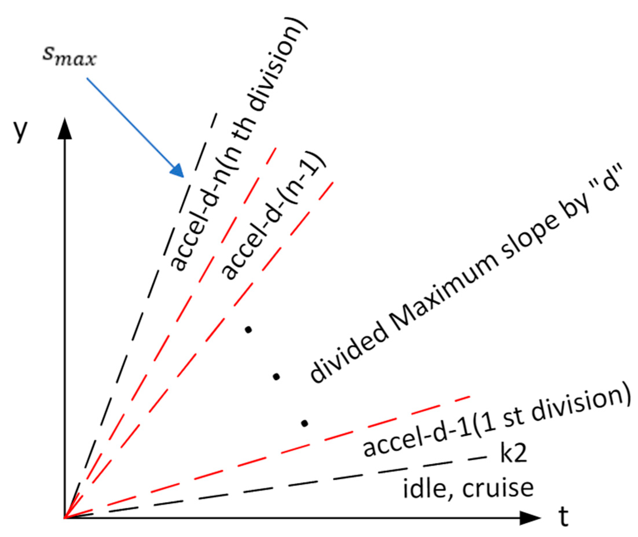
| acceleration | slope angle range(~ ) |
| deceleration | slope angle range(~ ) |
| accel-d-1 | 1st division of slope angle range( ~ ) divided by d (n ) |
| accel-d-2 | 2nd division of slope angle range(~ ) divided by d (n ) |
| … | … |
| accel-d-n | n-th division of slope angle range( ~ ) divided by d (n ) |
| decel-d-1 | 1st division of slope angle range(~ ) divided by d (n ) |
| decel-d-2 | 2nd division of slope angle range(~ ) divided by d (n ) |
| … | … |
| decel-d-n | n-th division of slope angle range(~ ) divided by d (n ) |
| Modal Event | Formulas |
|---|---|
| idle | < and < |
| cruise | < and > |
| acceleration | > |
| deceleration | < |
| accel-d-1 | > and ~ 1 |
| accel-d-2 | > and 1 ~ 2 |
| … | … |
| accel-d-n | > and (n-1) ~ n |
| decel-d-1 | < and ~ |
| decel-d-2 | < and +1 ~ |
| … | … |
| decel-d-n | < and +(n-1) ~ n |
| Snippet Group | Formulas |
|---|---|
| Group A | − > 0 |
| Group B | − < 0 |
| Voyage Record | ||
|---|---|---|
| 1 November 2021 | 10:36 Stand by in KMOU 11:42 Ocean going from KMOU | Stand by 1.1 h |
| 2 November 2021 | 09:30 Stand by at Masan 12:42 Engine stop | Sailing 21.8 h Stand by 3.2 h |
| 3 November 2021 | 09:36 Stand by in Masan 11:12 Ocean going to KMOU | Stand by 1.6 h |
| 4 November 2021 | 09:00 Stand by at KMOU 10:36 Engine stop | Sailing 21.8 h Stand by 1.6 h |
| Voyage Record | ||
|---|---|---|
| 25 June 2022 | 12:54 Stand by in KMOU 13:30 Ocean going from KMOU | Stand by 0.6 h |
| 26 June 2022 | 08:30 Stand by at Ulleung 10:00 Engine stop | Sailing 19.0 h Stand by 1.5 h |
| 27 June 2022 | 15:42 Stand by Eng for Dep. from Ulleung 16:06 Ocean going to KMOU | Stand by 0.4 h |
| 28 June 2022 | 06:00 Stand by at KMOU 07:30 Engine stop | Sailing 13.9 h Stand by 1.5 h |
| Voyage Record | ||
|---|---|---|
| 29 November 2021 | 10:06 Stand by in KMOU 10:42 Ocean going from KMOU | Stand by 0.6 h |
| 30 November 2021 | 13:30 Stand by in Incheon 14:18 Engine stop | Sailing 26.8 h Stand by 0.8 h |
| 1 December 2021 | 13:12 Stand by in Incheon 13:48 Ocean going from Incheon | Stand by 0.6 h |
| 2 December 2021 | 15:00 Stand by in KMOU 17:00 Engine stop | Sailing 25.2 h Stand by 2.0 h |
| Items | Contents |
|---|---|
| Mode purpose | Fuel efficiency measurement |
| Type of ship | Training ship |
| Sailing route | KMOU–Masan–KMOU, KMOU–Ulleung–KMOU, KMOU–Incheon–KMOU |
| Y-axis value “y” | Speed (knot) and power (kW) |
| Maximum design power | 6618 kW |
| Maximum design speed | 18.5 knot |
| “d” of the modal event | 5 |
| “m” of Residual m group | 10 |
| The number “k” of snippets based on the mode | 100 |
| Sailing Modes | y-Axis Value “y” |
|---|---|
| Stand by mode | kW |
| Port out (v = 0) mode | kW |
| Port out mode | knot |
| Navigation mode | knot |
| Port in mode | knot |
| Port in (v = 0) mode | kW |
| The Representative Sailing Mode | Computation Time(s) |
|---|---|
| Stand by mode | 4130 |
| Port out (v = 0) mode | 4070 |
| Port out mode | 4110 |
| Navigation mode | 4030 |
| Port in mode | 3980 |
| Port in (v = 0) mode | 3970 |
| Modal Event | Number | Proportion(%) | Modal Event | Number | Proportion(%) |
|---|---|---|---|---|---|
| accel-5-1 | 58 | 11.3 | decel-5-1 | 58 | 9.3 |
| accel-5-2 | 61 | 11.9 | decel-5-2 | 61 | 7.6 |
| accel-5-3 | 59 | 11.5 | decel-5-3 | 59 | 9.1 |
| accel-5-4 | 59 | 11.5 | decel-5-4 | 59 | 7.8 |
| accel-5-5 | 56 | 10.9 | decel-5-5 | 56 | 9 |
| Modal Event | Number | Proportion(%) | Modal Event | Number | Proportion(%) |
|---|---|---|---|---|---|
| accel-5-1 | 64 | 12.6 | decel-5-1 | 35 | 6.9 |
| accel-5-2 | 56 | 11 | decel-5-2 | 40 | 7.9 |
| accel-5-3 | 73 | 14.4 | decel-5-3 | 29 | 5.7 |
| accel-5-4 | 60 | 11.8 | decel-5-4 | 45 | 8.9 |
| accel-5-5 | 67 | 13.2 | decel-5-5 | 38 | 7.5 |
| Modal Event | Number | Proportion(%) | Modal Event | Number | Proportion(%) |
|---|---|---|---|---|---|
| accel-5-1 | 79 | 18.2 | decel-5-1 | 10 | 2.3 |
| accel-5-2 | 49 | 11.3 | decel-5-2 | 16 | 3.7 |
| accel-5-3 | 93 | 21.5 | decel-5-3 | 12 | 2.8 |
| accel-5-4 | 72 | 16.6 | decel-5-4 | 13 | 3 |
| accel-5-5 | 79 | 18.3 | decel-5-5 | 9 | 2 |
| Modal Event | Number | Proportion(%) | Modal Event | Number | Proportion(%) |
|---|---|---|---|---|---|
| accel-5-1 | 20 | 6 | decel-5-1 | 34 | 10.3 |
| accel-5-2 | 42 | 12.8 | decel-5-2 | 34 | 10.3 |
| accel-5-3 | 31 | 9.4 | decel-5-3 | 36 | 10.9 |
| accel-5-4 | 29 | 8.8 | decel-5-4 | 36 | 10.9 |
| accel-5-5 | 32 | 9.7 | decel-5-5 | 35 | 10.6 |
| Modal Event | Number | Proportion(%) | Modal Event | Number | Proportion(%) |
|---|---|---|---|---|---|
| accel-5-1 | 13 | 3 | decel-5-1 | 72 | 16.4 |
| accel-5-2 | 22 | 5 | decel-5-2 | 72 | 16.4 |
| accel-5-3 | 14 | 3.2 | decel-5-3 | 72 | 16.4 |
| accel-5-4 | 14 | 3.2 | decel-5-4 | 71 | 16.2 |
| accel-5-5 | 21 | 4.8 | decel-5-5 | 67 | 15.3 |
| Modal Event | Number | Proportion(%) | Modal Event | Number | Proportion(%) |
|---|---|---|---|---|---|
| accel-5-1 | 42 | 8.5 | decel-5-1 | 54 | 10.9 |
| accel-5-2 | 50 | 10 | decel-5-2 | 52 | 10.5 |
| accel-5-3 | 41 | 8.2 | decel-5-3 | 52 | 10.5 |
| accel-5-4 | 48 | 9.7 | decel-5-4 | 50 | 10 |
| accel-5-5 | 46 | 9.3 | decel-5-5 | 62 | 12.5 |
| Sailing Modes | Chi-Square Value |
|---|---|
| Stand by mode | 0.014 |
| Port out (v = 0) mode | 0.197 |
| Port out mode | 0.246 |
| Navigation mode | 0.188 |
| Port in mode | 0.032 |
| Port in (v = 0) mode | 0.074 |
Disclaimer/Publisher’s Note: The statements, opinions and data contained in all publications are solely those of the individual author(s) and contributor(s) and not of MDPI and/or the editor(s). MDPI and/or the editor(s) disclaim responsibility for any injury to people or property resulting from any ideas, methods, instructions or products referred to in the content. |
© 2024 by the authors. Licensee MDPI, Basel, Switzerland. This article is an open access article distributed under the terms and conditions of the Creative Commons Attribution (CC BY) license (https://creativecommons.org/licenses/by/4.0/).
Share and Cite
Moon, C.; Jeong, S.; Roh, G.; Park, K. Development of Representative Sailing Mode Construction Methodology Using Markov Chain. J. Mar. Sci. Eng. 2024, 12, 329. https://doi.org/10.3390/jmse12020329
Moon C, Jeong S, Roh G, Park K. Development of Representative Sailing Mode Construction Methodology Using Markov Chain. Journal of Marine Science and Engineering. 2024; 12(2):329. https://doi.org/10.3390/jmse12020329
Chicago/Turabian StyleMoon, Changjae, Sanghun Jeong, Giltae Roh, and Kido Park. 2024. "Development of Representative Sailing Mode Construction Methodology Using Markov Chain" Journal of Marine Science and Engineering 12, no. 2: 329. https://doi.org/10.3390/jmse12020329
APA StyleMoon, C., Jeong, S., Roh, G., & Park, K. (2024). Development of Representative Sailing Mode Construction Methodology Using Markov Chain. Journal of Marine Science and Engineering, 12(2), 329. https://doi.org/10.3390/jmse12020329