Article

The Wide-Area Coverage Path Planning Strategy for Deep-Sea Mining Vehicle Cluster Based on Deep Reinforcement Learning

1
College of Engineering Science and Technology, Shanghai Ocean University, Shanghai 201306, China
2
Shanghai Zhongchuan NERC-SDT Co., Ltd., Shanghai 201114, China
*
Author to whom correspondence should be addressed.
J. Mar. Sci. Eng. 2024, 12(2), 316; https://doi.org/10.3390/jmse12020316
Submission received: 10 January 2024 / Revised: 6 February 2024 / Accepted: 8 February 2024 / Published: 12 February 2024
(This article belongs to the Section Ocean Engineering)

Abstract

:
The path planning strategy of deep-sea mining vehicles is an important factor affecting the efficiency of deep-sea mining missions. However, the current traditional path planning algorithms suffer from hose entanglement problems and small coverage in the path planning of mining vehicle cluster. To improve the security and coverage of deep-sea mining systems, this paper proposes a cluster-coverage path planning strategy based on a traditional algorithm and Deep Q Network (DQN). First, we designed a deep-sea mining environment modeling and map decomposition method. Subsequently, the path planning strategy design is based on traditional algorithms and DQN. Considering the actual needs of deep-sea mining missions, the mining vehicle cluster path planning algorithm is optimized in several aspects, such as loss function, neural network structure, sample selection mechanism, constraints, and reward function. Finally, we conducted simulation experiments and analysis of the algorithm on the simulation platform. The experimental results show that the deep-sea mining cluster path planning strategy proposed in this paper performs better in terms of security, coverage, and coverage rate.

1. Introduction

There are massive deep-sea mineral resources stored in the deep-sea basin area [1]. Among these mineral resources, the ones with the most economic and development value are mainly polymetallic nodules and polymetallic sulfide deposits containing gold, silver, copper, zinc, cobalt, copper, nickel, manganese, and other mineral resources [2,3]. These mineral resources are widely distributed in the flat seabed surface layer at depths of 4000 to 6000 meters in the form of sediments half-buried on the seafloor surface. Therefore, it is necessary to design a specialized deep-sea mining system to carry out mining operations in such environmental conditions. Based on the task requirements and actual conditions of deep-sea mining, countries around the world have successively proposed various design schemes for deep-sea mining systems [4,5,6]. Deep-sea mining systems typically consist of three main components: the seabed mining sub-system, the pipeline lifting sub-system [7,8,9], and the surface storage and transportation sub-system. The seabed mining subsystem is the most critical and complex link in the entire deep-sea mining system. The main purpose of the seabed mining sub-system is to collect mineral resources from deep-sea sediments and perform preprocessing tasks such as screening, cleaning, and crushing, thus reducing the difficulty of transporting and lifting the mineral resources [10]. After completing the above work, the processed mineral resources will be transported to the relay station in the pipeline-lifting sub-system and lifted to the surface mining vessel.
As the core of the deep-sea mining system, seabed mining equipment determines the system’s overall efficiency. Mainstream seabed mining equipment can be categorized into towed and remotely operated self-propelled types based on their drive mechanisms. Some deep-sea mining systems use remotely operated underwater vehicles (ROV) to drag mining equipment for mining. As the equipment is powered by the towing force of the ROV, the disadvantages of this approach are lower motion control precision and weaker obstacle avoidance capability. Therefore, remotely operated self-propelled vehicles are more suitable for deep-sea mining systems.
Over the past few years, there have been unprecedented developments in unmanned mobile vehicles, which have wide applications in multiple fields such as logistics [11], minerals [12], agriculture [13], etc. Unlike those on land, deep-sea sediments are characterized by low shear strength, high adhesion [14], large pores, and some fluid properties. Traditional unmanned vehicles are not adapted to this particular environment and usually have problems with skidding or sinking. Currently, in deep-sea mining systems, using tracked unmanned vehicles [15,16,17] to collect seabed mineral resources is an internationally recognized optimal solution.
The main components of a deep-sea mining system include seabed mining vehicles [18,19,20], transportation hoses, relay stations, lifting hard pipes [21], and surface mining vessels [22,23,24]. The complete system structure is shown in Figure 1. Seabed mining vehicles are used to collect mineral resources and preprocess; transport hoses are employed to transport preliminarily processed mineral resources from the mining vehicles to the relay station; mineral resources will be temporarily stored in the relay station, and when the storage volume reaches a predetermined level, the relay station transports the mineral resources to the surface mining vessel by lifting the hard pipe; the surface mining vessel is responsible for cleaning, classifying and storing the resources, and then transporting them to the land.
Most of the mineral resources in the deep sea are in the form of nodules dispersed over wide environments. In deep-sea mining missions, mining vehicle clusters need to accomplish complete coverage of wide areas to collect mineral resources in seafloor sediments [25]. Therefore, the study of cluster-coverage path planning technology can help mining vehicles achieve efficient path planning for full coverage of the mining area and improve the comprehensive efficiency of the deep-sea mining system.
In recent years, many researchers have been working on coverage path-planning algorithms in different directions to solve various problems. Li [26] proposed a heuristic approximate credit-based Dubins multi-robot coverage path planning (CDM) algorithm, which utilizes the credit model to balance tasks among robots and a tree partition strategy to reduce complexity. Tan [27] proposed a complete coverage path planning algorithm based on Q-learning to solve the problems of local optimal path and high path coverage ratio in the complete coverage path planning of the traditional biologically inspired neural network algorithm. Lu [28] proposed Turn-minimizing Multirobot Spanning Tree Coverage Star (TMSTC*), an improved multirobot coverage path planning (mCPP) algorithm based on MSTC*. Ai [29] planned a search path that would be the least time-consuming and prioritized coverage of high-probability areas based on reinforcement learning, considering complete coverage of maritime SAR areas and avoiding maritime obstacles.
In terms of path-planning algorithms for robot clusters, some researchers have conducted relevant studies using several kinds of algorithms. Qiu [30] proposed using the BSO algorithm for unified scheduling and allocation of multiple robots to improve the efficiency of task execution. Dong [31] proposed a joint optimization algorithm of task assignment and flight path planning for a heterogeneous unmanned aerial vehicle (UAV) cluster in a multi-mission scenario (MMS). An optimized particle cluster hybrid ant colony (PSOHAC) algorithm was proposed by Yan [32] to plan the path of a UAV cluster task. Park [33] presented an online distributed trajectory planning algorithm for a quadrotor cluster in a maze-like dynamic environment. Zhang [34] proposed a novel strategy that integrates sensor area partitioning and flight trajectory planning for multiple UAVs, forming an optimization framework geared towards minimizing task completion duration. Chen [35] proposed a cooperative hunting method for multi-USV based on the A* algorithm in an environment with obstacles and a biomimetic multi-USV cluster collaborative hunting method. Baras [36] introduced an innovative methodology that employs Affinity Propagation (AP) for area allocation in multi-robot CPP. In this approach, the area is partitioned into ‘n’ clusters through AP, with each cluster subsequently assigned to a robot. A new framework of team-based multi-robot task allocation and path planning is developed for robot exploration missions through a convex optimization-based distance optimal model by Lei [37].
This paper studies the path planning problem of wide-area coverage for a deep-sea mining vehicle cluster. We used deep learning techniques to implement the design of a wide-area coverage path planning algorithm for a deep-sea mining vehicle cluster. Based on the path planning of the mining vehicle cluster, we also considered the movement strategy of the relay station and used the inner spiral algorithm to plan the movement route of the relay station, thus indirectly expanding the coverage of the mining vehicle cluster. In addition, this paper also designs and uses a variety of constraints to achieve collaboration between the mining vehicle cluster and the relay station.
After completing the above algorithm design, we conducted multiple simulation experiments. The simulation experiment results show that the proposed path planning strategy can complete the mission with good performance in many different situations.

2. Technical Method

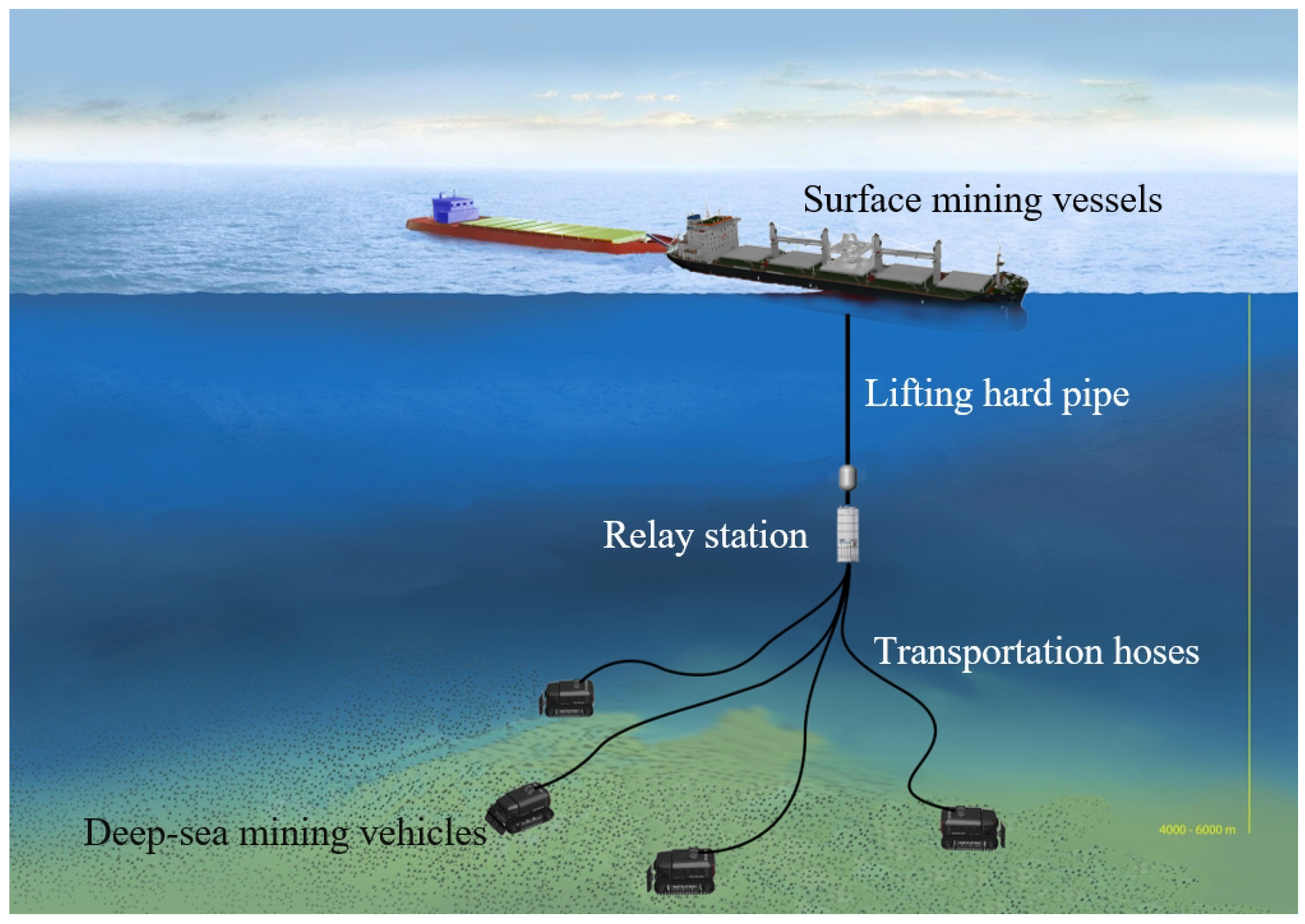
2.1. Deep-Sea Environmental Modeling

Mining vehicle clusters need path planning algorithms to provide safe and efficient action paths for mining operations in deep-sea environments, while the algorithms need to be aware of the current environment information and the current position of the mining vehicles to perform effective path planning. Therefore, we began by establishing the environment space model of mining vehicles based on the deep-sea environment. At present, deep-sea environment detection mainly uses acoustic technology to measure the depth of the seafloor and establishes a three-dimensional model of the deep-sea seafloor environment based on the depth data. However, due to technical constraints, the error of the depth data used to establish the deep-sea environment model is about 1% of the measured depth. For deep-sea mining missions, the depth of the environment in which the mining vehicles are located is typically in the kilometer range.
Therefore, the three-dimensional model established based on acoustic technology is not suitable for direct use in path planning. Based on the movement capabilities of deep-sea mining vehicles and using the depth data of the seabed mining environment, the three-dimensional seabed environment can be converted into a two-dimensional grid map model. The specific processing process is as follows: We use grayscale values to represent the depth of each location in the deep-sea mining area, and grids with different grayscale values represent areas of different depths in the seabed mining area. If the depth gap between a certain grid and other grids exceeds the movement capacity of deep-sea mining vehicles and causes the mining vehicle to be unable to pass through the grid successfully, the area should be set as an uncoverable area. Otherwise, it can be considered a safe area that can be covered. Based on the above process, the three-dimensional depth model is converted into a two-dimensional grid map as shown in Figure 2.
This picture describes a two-dimensional grid map established based on the depth data of the seafloor mining environment. The unit of data is meters. Different gray values in the figure represent different depths in the deep-sea mining environment. As mentioned previously, based on the depth gap between a single grid and other grids, these grids can be divided into coverable and non-coverable grids, represented by white and black, respectively. The basis for grid-type division needs to be determined by the upper limit of the deep-sea mining vehicle’s actual movement capability. According to the actual size and movement capacity of the current deep-sea mining vehicles, we set the basis for the division of grid type as 3.5 m. If the topographical variation of the deep-sea environment exceeds 3.5 m, the area can be regarded as a non-coverable area; conversely, it is regarded as a coverable area.
After streamlining the environment information to obtain the grid map, we can further process it. The current environment A of the mining vehicle is defined as a state matrix containing m × n elements:
p 1 , 1 p 1 , n p m , 1 p m , n
where m and n represent the length and width of the grid map, and p represents the environmental state of the corresponding location on the grid map. We use different values to represent different states, as shown in Table 1 below:
After the grid map and state matrix representing the deep-sea environment are set up, if the mining vehicle executes the action a t , the state space will also change, and our state matrix will change as well. The transition from the current state s t to the next state s t + 1 can be described as follows:
s t + 1 = s t ( p i 1 , j = p i , j , p i , j = 1 ) , a t = 0 s t ( p i , j 1 = p i , j , p i , j = 1 ) , a t = 1 s t ( p i + 1 , j = p i , j , p i , j = 1 ) , a t = 2 s t ( p i , j + 1 = p i , j , p i , j = 1 ) , a t = 3
where the next position p i ± 1 , j ± 1 is set as the current area of mining vehicle, and the current position p i , j is set as the covered area. The four values of a t from 0 to 3 represent up, left, down, and right.

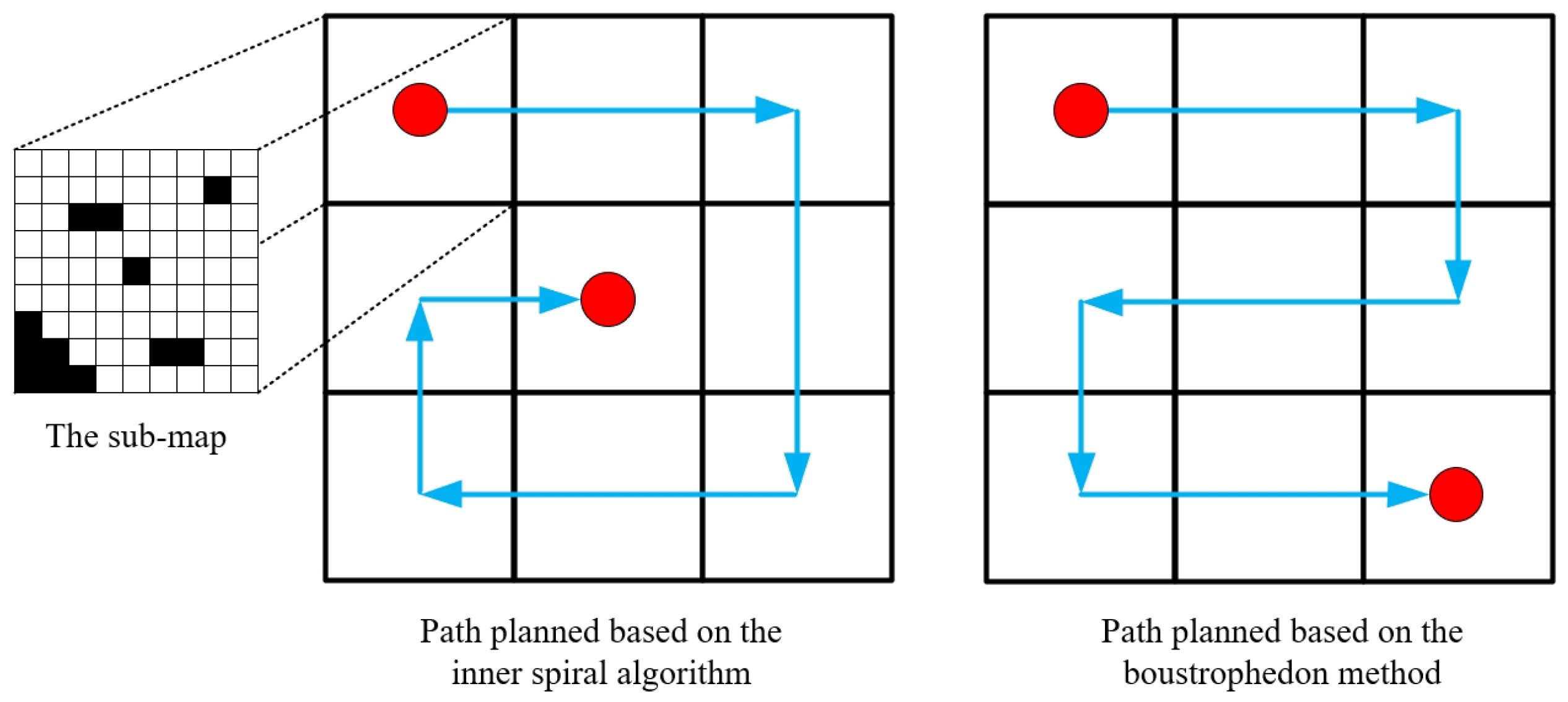
2.2. Map Decomposition

As mentioned in Section 1, the deep-sea mining vehicle is connected to the relay station through a transport hose, so the movement range of the mining vehicle is limited by the length of the hose. To cover as much of the deep-sea mining area as possible, we need to divide the larger complete mining area map into smaller sub-maps that are connected. To ensure the safety of the deep-sea mining system, the maximum distance between the deep-sea mining vehicle and the relay station must be less than the transport hose’s maximum length 1 2 L d i a 1 . With the above requirements, the range of action of the mining vehicle is a circle. However, if the circular motion range is directly used for map decomposition, there will be gaps between each circular sub-map, resulting in the omission of some seafloor mining areas that need to be covered. To ensure full coverage of the mining area and to facilitate the switching of mining vehicles between sub-maps, the map needs to be divided into rectangles. This requires finding the inscribed rectangle with the largest area S r e c t within the circular motion range of the mining vehicle. According to Equation (3):
S r e c t = L d i a 1 L d i a 2 s i n θ 2
where L d i a 1 , L d i a 2 are the two diagonals of the rectangle, θ represents the angle between the diagonals, and S r e c t represents the area of the rectangle. From the above equation, when θ is 90°, it can be seen that the largest area within the circle is the square with the diameter as the diagonal. Therefore, we decompose the map in this shape, as shown in Figure 3 below.
Once the complete mining area map has been divided into sub-maps, the mining vehicle cluster will execute the coverage mission of the current sub-map at first. After completing the coverage of the current area, the deep-sea mining system will control the relay station and move it to the center point of the next sub-map, and the mining vehicle cluster will also switch to the next sub-map for a new area coverage mission. The deep-sea mining system repeats the above process as a way to achieve wide area coverage.

3. Design and Optimization of Algorithms

3.1. Design of Path Planning Strategy for Relay Station

Based on the map decomposition method, we divide the mining area into several sub-maps. Due to the limited action range of mining vehicles, to accomplish the goal of wide-area coverage, the relay station must follow a predetermined path to expand the action range of mining vehicles. Therefore, it is necessary to study the action path planning strategy of relay stations.
If the individual sub-maps are considered as a grid, from the result of the map decomposition, we can obtain a new grid map. Each grid in this map represents a sub-map of the mine. The study of the movement path strategy of the relay station is based on this grid map. Since the relay station is usually located in seawater and connected to the lifting hard pipe at a certain distance from the seabed, there are usually no obstacles or dangerous areas within the movement range of the relay station. In addition, the relay station also needs to stay in the center of the sub-map to ensure that the mining vehicle’s action range can cover the entire sub-map.
Based on the above conditions, the environment where the relay station is located can be regarded as a regular and obstacle-free environment, and its coverage path planning strategy does not need to use a very complex algorithm. The traditional inner spiral algorithm or boustrophedon method can meet the requirements. We choose to use the inner spiral algorithm as the coverage path planning strategy for relay stations. The result is shown in Figure 4 below:

3.2. Design of Path Planning Algorithms for Mining Vehicle Cluster

Reinforcement learning theory allows the agent to interact with the environment and select actions based on a strategy to maximize rewards. The agent accumulates a large amount of learning experience in the environment, learns from mistakes, and updates the strategy. The interaction process between the agent and the environment is usually represented by a Markov decision process.
At any time step t, the agent is in its current environmental state s t . When the agent selects an action a t and executes it in the environment, it will receive a reward value r t , and the state of the environment will be updated to the next state s t + 1 according to the state transition function P. Reinforcement learning algorithms select actions for the agent through action selection strategy π ( a | s ) . Action selection strategies can be divided into two types: random and deterministic [38,39]. The stochastic strategy randomly selects actions based on probability, and the deterministic strategy selects actions based on state s t . Q-learning is a classical reinforcement learning algorithm with the following policy iteration formula:
Q ( s t , a t ) Q ( s t , a t ) + α ( r t + γ m a x Q ( s t + 1 , a t + 1 ) Q ( s t , a t ) )
The disadvantage of Q-learning is that it is not suited to handling high-dimensional complex problems. This is also a common problem with reinforcement learning algorithms [40]. Q-learning counts and iterates the evaluated values (Q-values) of actions based on states that have appeared in the past. If the state and action space is large, the efficiency of Q-learning will be greatly decreased. On the other hand, Q-learning cannot handle states that have never appeared.
The deep reinforcement learning algorithm introduces the neural network on the original basis and uses the neural network to predict the action evaluation value of the unknown state. The addition of neural networks not only solves the problem of reinforcement learning’s adaptability to unfamiliar states but also improves the efficiency of the algorithm when facing complex problems [41,42]. The most common deep reinforcement learning algorithms available today are Deep Q Network (DQN), Asynchronous Advantage Actor-Critic (A3C), and Deep Deterministic Policy Gradient (DDPG).
Based on the DQN algorithm, we study the coverage path planning mission of deep-sea mining vehicle cluster. The traditional DQN algorithm does not perform well when dealing with the mission of cluster-coverage path planning. Based on the actual requirements of the deep-sea mining mission, we make a series of improvements to the DQN algorithm to enhance its performance in cluster-coverage path planning. The optimization problem set in this article is to maximize the algorithm coverage and minimize the loss function through the limitation of the set angle-based constraints and the feedback of the reward function.
The algorithm sets up two neural networks with the same structure, which are defined as Q-target and Q-eval, respectively. The algorithm selects actions using Q-target and evaluates them using Q-eval. The two neural networks perform parameter synchronization at intervals. The algorithm inputs the current environment state s t into Q-eval to obtain the Q-values of all the actions in the action space. Then, the intelligent body selects the optimal action based on the Q-values and executes it in the environment to reach the next state s t + 1 and the corresponding reward value r t . These data are saved to the training sample repository. After accumulating a predetermined number of training samples, the algorithm extracts data from the training sample repository to train the neural network.
After the training samples are input into Q-target and Q-eval simultaneously, two different sets of results will be calculated. The algorithm uses the difference between these two data sets to calculate the neural network’s loss function. The loss function is used to update the parameters of the neural network for Q-eval, which determines the speed of convergence of the neural network. Based on the computation results of the two neural networks, the algorithm calculates the loss function and uses the obtained data to update the neural network parameters of Q-eval. In addition, the parameters of the two neural networks are synchronized at intervals. Different problems have different requirements for loss functions. Currently, commonly used loss functions include the mean absolute error function and the mean square error function. For the cluster-coverage path planning problem of deep-sea mining, the loss function we use combines the characteristics of the above two functions. The specific definition of the function is as follows:
L o s s = 1 2 Q ( s , a ) [ r + γ max a A Q ( s , a ; θ ) ] 2 , | Q ( s , a ) [ r + γ max a A Q ( s , a ; θ ) ] | < 1 | Q ( s , a ) [ r + γ max a A Q ( s , a ; θ ) ] | 1 2 , o t h e r w i s e
In simulation tests, the loss function we use effectively enhances the stability of the algorithm and the convergence speed of the neural network.
The neural network structure has also been modified and optimized to adapt to the requirements of the deep-sea mining mission. The path planning task needs to incorporate the current environmental information. The neural network first inputs the state matrix into the convolution layer to extract the mining area environmental information and mining vehicle position information and then uses the ReLU activation function to mine relevant features, fit the training data and accelerate the convergence of the neural network. We removed the common pooling layer in neural networks to retain all the information of the state matrix as much as possible and avoid losing effective environmental data during the pooling process. The algorithm also introduces a long- and short-term memory mechanism (LSTM) to correlate successive state matrix information and enhance the effectiveness of the neural network. After completing the above processing steps, the algorithm uses a fully connected layer to weight the previously obtained features and integrate the feature representation into a concrete numerical representation. The final output of the fully connected layer is the evaluation value of all actions in the action space. The specific structure of the neural network is shown in Figure 5 below.
The last step is to optimize the selection mechanism of training samples. Using high-quality training samples for neural network training can effectively improve the convergence speed. To define the quality of training samples, we calculate the priority of each training result based on the coverage and path length, and the sample priority data are stored using a binary tree structure. In the training process of neural networks, the higher the priority of the samples, the higher the probability of being selected. This method can ensure the randomness of sample selection based on fully utilizing the training value of high-quality samples. The formula for calculating the sample priority is shown below:
V p = ( s c o v e r S ) α β L
where V p represents the sample prioritization parameter, α and β are the adjustment factors, s c o v e r represents the covered area, S represents the total area of the current sub-map, and L is the length of the planned path.
Based on the above optimization method, the structure of the proposed algorithm in this paper is shown in Figure 6.

3.3. Design of Constraints

In cluster-coverage path planning, it is usually necessary to set constraints to implement specific functions or solve special problems. Common constraints mainly include energy constraints, time constraints, and distance constraints.
As mentioned in Section 1, the distance between the mining vehicle and the relay station should be less than the length of the transport hose to ensure system safety. According to this requirement, we set the corresponding constraints as follows:
0 L d i s t a n c e 0.8 L h o s e
To ensure the safety of the deep-sea mining system, the maximum distance L d i s t a n c e between the deep-sea mining vehicle and the relay station must be less than or equal to 80% of the transport hose’s maximum length L h o s e .
The main problem that needs to be solved in this study is the problem of hose entanglement between the deep-sea mining vehicle and the relay station. The deep-sea mining vehicle and the relay station are connected through hoses to realize mineral resource transportation, mining vehicle energy supply, and data communication. Due to the presence of hoses, collaborative operations among mining vehicles may result in hose entanglement, which poses a safety risk to the system. The introduction of angle-based constraints effectively eliminates the problem of hose entanglement between mining vehicles.
In the deep-sea mining system we designed, there are four deep-sea mining vehicles working together. Based on the current location information of the mining vehicle and the relay station, we can create a straight line connecting the mining vehicle and the relay station. This straight line can be approximated as a transport hose. There will be an included angle between every two adjacent straight lines, and four mining vehicles will produce four included angles, as shown in Figure 7. As long as these four included angles are greater than or equal to zero at any time, no matter how the position of the deep-sea mining vehicle changes, there will be no problem of hose entanglement.

3.4. Design of Reward Function

In deep learning, the algorithm selects different actions and executes them in the environment, and the reward function gives the algorithm a positive or negative reward value based on the result after execution. The role of the reward function may seem to be simply to evaluate the actions chosen by the algorithm based on the results of the execution, but it is essentially used to control the algorithm, ensuring that it keeps trying to accomplish the goal of the mission that we have set. However, the algorithm will only learn how to maximize the reward value. If we need the algorithm to achieve a certain goal, we must ensure that the algorithm will achieve the task goal while maximizing the reward value through the reward function. The setting of the reward function determines the trend and effect of the algorithm’s learning and training, and also greatly affects the convergence speed of the neural network.
For the path planning mission of deep-sea mining, the goals that need to be achieved mainly include four aspects: safety, coverage, coverage efficiency, and collaboration. Undoubtedly, the most fundamental goal is to ensure the safety of the system, so safety should be set as the mainline reward of the reward function. The other three points are the goals that the algorithm needs to try its best to achieve while ensuring system security, and these are set as auxiliary rewards.
To ensure the safety of deep-sea mining systems, it is necessary to prevent mining vehicles from colliding with each other, entering dangerous areas or violating constraints. If the above situation occurs, the reward function must give the algorithm a punitive negative reward and end this training episode.
r m a i n = 10 , a c c i d e n t o c c u r s 0 , e l s e
In addition to the safety issues, it is also necessary to set up some auxiliary reward functions to improve the performance of the path-planning algorithm. Coverage is an important indicator of the evaluation algorithm, and we need to make the algorithm cover a larger mining area, so we design an incentive reward function r c o v for it:
r c o v = 0.2 N c o v + μ N c o v N a l l
where N c o v is the amount of covered grid, N a l l is the total amount of current sub-map grid, and μ is the adjustment factor.
Due to the constraints mentioned in the previous section, mining vehicles sometimes have to enter areas that have already been covered. However, too much repetition in the covered area will increase the system’s energy consumption and reduce work efficiency. Therefore, it is necessary to minimize the repetition rate of the algorithm’s planning path, and the corresponding auxiliary reward r r e p function is shown below:
r r e p = 0.05 N r e p λ N r e p N a l l
where N r e p is the amount of repeated coverage grid and λ is the adjustment factor.
The wide-area coverage capability of the deep-sea mining system requires algorithms to consider the transfer of mining vehicle clusters between sub-maps. The system wants the mining vehicle cluster to move to the next sub-map more conveniently. In that case, we need the mining vehicle to be as close as possible to the boundary connecting the next sub-map when completing the coverage mission of the current map. The reward function to achieve the above goal is as follows:
r d i s = 5 e L d i s
where L d i s is the distance between the position of the mining vehicle and the target boundary.
The total reward R t o t a l can then be expressed as a linear superposition of the multiple reward functions described above:
R t o t a l = r m a i n + r c o v + r r e p + r d i s

4. Algorithm Simulation and Discussion

4.1. Simulation Platform and Parameters

To verify the effectiveness of the algorithm proposed in this paper, we designed and conducted simulation experiments. The simulation experiment in this paper runs on Windows 10, using Python (3.11) as the development language and PyTorch as the deep learning framework. The specific parameters of the simulation platform are shown in Table 2.
In the above simulation environment, we conducted simulation experiments on the improved algorithm designed in this paper. The algorithm is trained 10,000 times, the learning rate is 0.001, the initial value of the percentage of follow-me action selection is 0.5, the sample storage capacity is 100,000, the mining environment is set as a 27 × 27 grid map and the sub-map is set as a 9 × 9 grid map.
The neural network is composed of three convolutional layers, one lstm layer and three fully connected layers. The specific parameters of the neural network are shown in Figure 5; each neuron of the convolutional layer and the fully connected layer is followed with the ReLu activation function. The last layer outputs the Q value of all actions in the action space. The loss function is optimized with SGD optimizer. The parameter values currently in training are shown in Table 3.
For the traditional DQN algorithm, we set its learning rate as 0.01, and other parameters are consistent with the algorithm proposed in this article. The difference in the learning rate is due to the deep algorithm needing to choose the appropriate learning rate parameter, and for the traditional DQN algorithm, using the same learning rate parameter as the proposed algorithm will lead to poor convergence. The above parameter values lead to better training results after multiple training sessions. If different parameters are used, the algorithm training results may decrease to different degrees.

4.2. Simulation Results

In the simulation process, the environment parameters and neural network model parameters are initialized first, and then the grid map of the mining environment is constructed. Then, the grid map is divided into several sub-maps according to the requirements. In this simulation experiment, the mine map can be divided into nine sub-maps. Firstly, the moving path of the relay station is planned according to the inner helix algorithm, and then the coverage path of the mining vehicle cluster for the current area is planned. After completing the coverage task of the current sub-map, the relay station moves to the center position of the next sub-map. Due to the conditions previously set in the reward function, the mining vehicle cluster is on the boundary between the current sub-map and the next sub-map upon completion of the coverage mission. Here, the mining vehicle cluster only needs to move one step towards the relay station to enter the next sub-map area. Completing the cluster-coverage of the wide-area mining environment requires that the above process be repeated.
The results of the simulation experiment are shown in Figure 8. In simulation experiments with different scenarios, the algorithm proposed in this article can complete the task with 100% coverage. Under the same mission requirements and constraints, traditional algorithms, such as the inner spiral algorithm and the boustrophedon method, often fail to accomplish this task. A gif version of the simulation experiment results is available online: https://github.com/Einzoth/fig8 (accessed on 2 February 2024).
The loss function diagram of Traditional DQN and the algorithm proposed in this paper are shown in Figure 9, where the y-axis is the gap between the path and the optimal path, and the x-axis is the number of training episodes.
Compared with the traditional DQN algorithm, the proposed algorithm in this paper performs better in terms of the convergence speed and simulation results. The average number of steps required by the traditional DQN algorithm to complete the coverage mission is 64.33, while the algorithm proposed in this article only requires an average of 58.5 steps, which is an improvement of 9.1%. In addition, in terms of task adaptability, due to the angle constraints of our design, our proposed algorithm can effectively avoid the hose entanglement problem and ensure system safety compared with the traditional DQN algorithm.

5. Conclusions

5.1. Main Result

Based on the requirements of deep-sea mining missions, this paper conducted relevant research and proposed a series of design and optimization methods for the problems and deficiencies of the current wide-area cluster coverage algorithms.
1.
A deep-sea mining area environment modeling method and map decomposition method were proposed, and were able to effectively process the original map data.
2.
Based on actual conditions, appropriate path-planning strategies were designed for relay stations and mining vehicle clusters using traditional algorithms and deep reinforcement learning algorithms.
3.
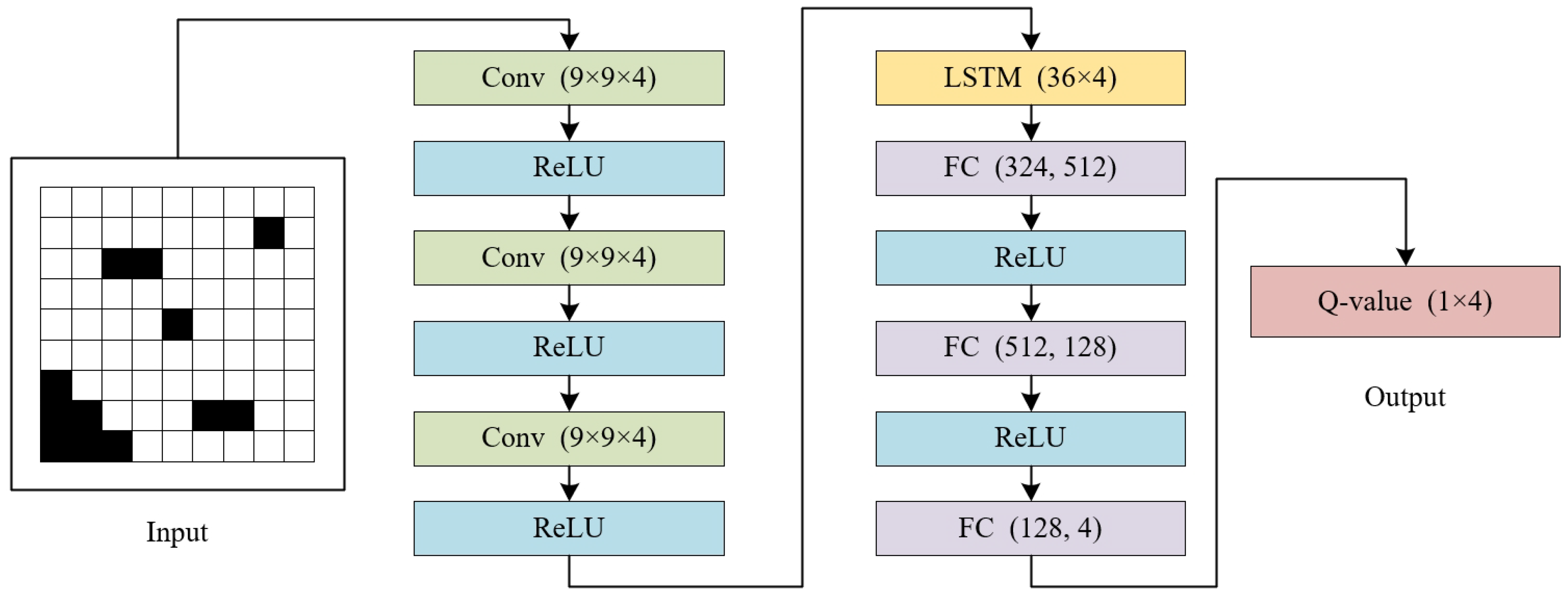
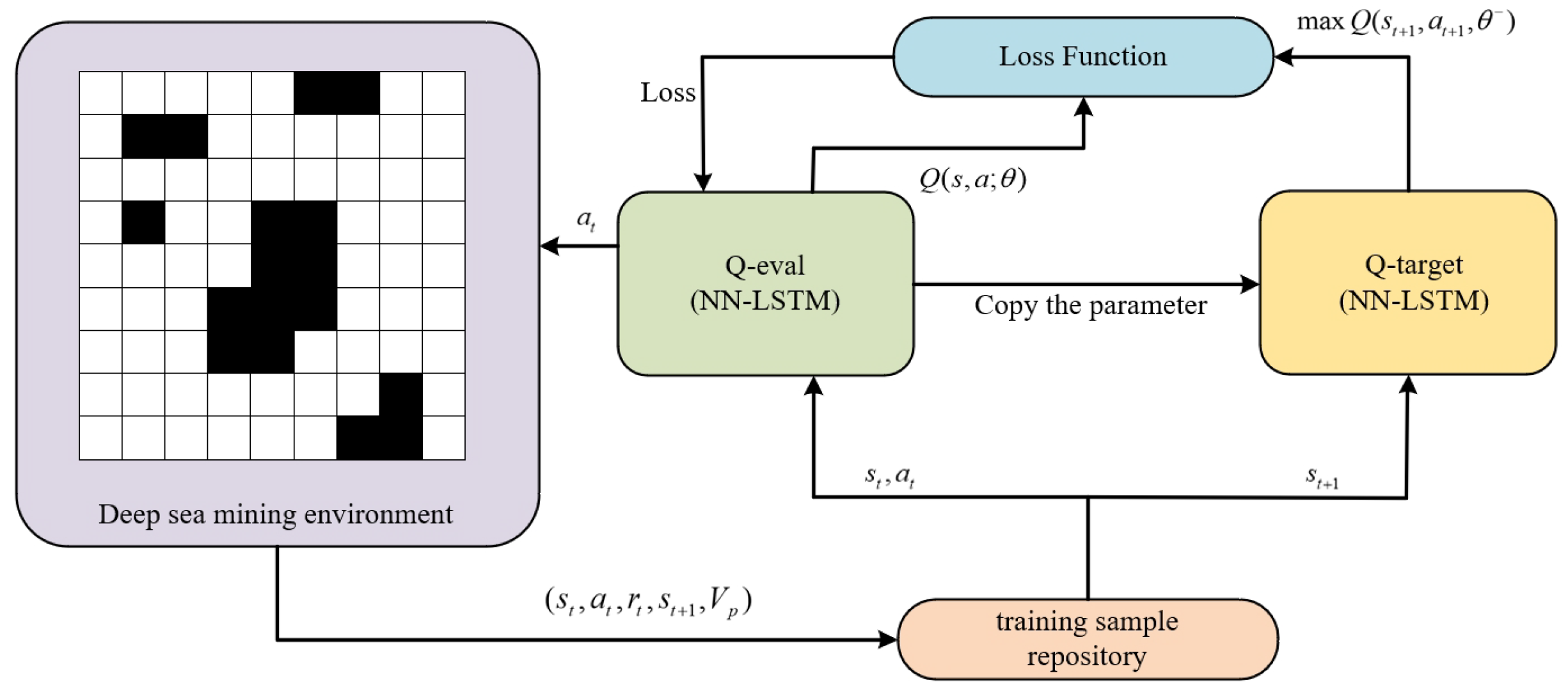
A series of DQN optimization methods were proposed. The loss function, neural network structure and sample selection mechanism of traditional DQN were improved based on the requirements of deep-sea mining missions.
4.
Considering the safety, coverage, efficiency and transfer of mining vehicles between sub-maps, a suitable reward function was designed for the path-planning algorithm of deep-sea mining tasks.
5.
The angle-based constraint was designed to solve the hose entanglement problem in deep-sea mining missions.
The simulation experiments showed that the path planning strategy proposed in this paper can effectively accomplish the wide-area coverage mission under the limitations of deep-sea mining requirements and constraints. Compared with traditional algorithms, our algorithm has better coverage and faster convergence speed, realizes cooperative path planning for mining vehicle clusters and improves the overall work efficiency of the deep-sea mining system.

5.2. Main Limitation of the Method

First of all, the actual conditions of the deep-sea environment and the mining vehicle cluster were not fully considered in the modeling stage, and the design of the action space was too simple. Secondly, to ensure system security, the constraints designed by the algorithm were too strict, which had a certain negative impact on the movement ability of the mining vehicle cluster. Finally, due to the limitations of research progress, we currently do not have the conditions to conduct actual experiments and test the actual performance of the proposed algorithm.

5.3. Future Research Prospects

The next stage of the work will focus on the following:
1.
Establishing a higher-precision kinematic model of mining vehicles to simulate the actual movement capabilities of mining vehicles;
2.
Optimizing the collaborative operation capabilities between mining vehicle cluster and relay stations;
3.
Continuing to improve the performance of the path planning algorithm and reducing the path coverage and energy consumption of mining vehicles while meeting basic requirements.
4.
Based on A3C and DDPG, we will work on further research about wide-area coverage path planning strategies for deep-sea mining vehicle clusters.
5.
To solve the twisting problem of hose, we will explore appropriate solutions in terms of constraint design or system hardware design.
6.
After completing the theoretical research at the pre-project stage of deep-sea mining, we will conduct experiments in actual environments to validate and improve the path-planning strategy proposed in this paper at the mid-project stage. Meanwhile, we will also collect and analyze the performance data of the proposed strategy in real experiments on deep-sea mining missions to further strengthen the paper’s contribution.

Author Contributions

Conceptualization, B.X. and X.W.; methodology, B.X.; software, X.W.; validation, B.X., X.W. and Z.L.; formal analysis, X.W.; investigation, X.W.; resources, B.X.; data curation, X.W.; writing—original draft preparation, X.W.; writing—review and editing, B.X. and Z.L.; visualization, X.W.; supervision, Z.L.; project administration, B.X.; funding acquisition, B.X. All authors have read and agreed to the published version of the manuscript.

Funding

This research was funded by Shanghai Science and Technology Committee (STCSM) Local Universities Capacity-building Project (No. 22010502200).

Institutional Review Board Statement

Not applicable.

Informed Consent Statement

Not applicable.

Data Availability Statement

The data are available on request.

Acknowledgments

The authors would like to express their gratitude for the support of Fishery Engineering and Equipment Innovation Team of Shanghai High-level Local University.

Conflicts of Interest

Author Zhenchong Liu was employed by the company Shanghai Zhongchuan NERC-SDT Co., Ltd. The remaining authors declare that the research was conducted in the absence of any commercial or financial relationships that could be construed as a potential conflict of interest.

References

  1. Yu, J.; Cui, W. Explore China’s stakeholders in the exploration and exploitation of mineral resources in deep seabed areas: Identification, challenges and prospects. Ocean Coast. Manag. 2023, 244, 106712. [Google Scholar] [CrossRef]
  2. Lv, X.; Zhong, Y.; Fu, G.; Wu, Y.; Xu, X. Revealing Heavy Metal-Resistant Mechanisms and Bioremediation Potential in a Novel Croceicoccus Species Using Microbial-Induced Carbonate Precipitation. J. Mar. Sci. Eng. 2023, 11, 2195. [Google Scholar] [CrossRef]
  3. Hammond, A.L. Manganese Nodules (II): Prospects for Deep Sea Mining. Science 1974, 183, 644–646. [Google Scholar] [CrossRef]
  4. Liu, Z.; Liu, K.; Chen, X.; Ma, Z.; Lv, R.; Wei, C.; Ma, K. Deep-sea rock mechanics and mining technology: State of the art and perspectives. Int. J. Min. Sci. Technol. 2023, 33, 1083–1115. [Google Scholar] [CrossRef]
  5. Li, B.; Jia, Y.; Fan, Z.; Li, K.; Shi, X. Impact of the Mining Process on the Near-Seabed Environment of a Polymetallic Nodule Area: A Field Simulation Experiment in a Western Pacific Area. Sensors 2023, 23, 8110. [Google Scholar] [CrossRef]
  6. Sha, F.; Xi, M.; Chen, X.; Liu, X.; Niu, H.; Zuo, Y. A recent review on multi-physics coupling between deep-sea mining equipment and marine sediment. Ocean Eng. 2023, 276, 114229. [Google Scholar] [CrossRef]
  7. Hu, Q.; Zhu, J.; Deng, L.; Chen, J.; Wang, Y. Effect of Particle Factors on the Reflux and Blockage of a Deep-Sea Six-Stage Pump Based on CFD-DEM. Adv. Theory Simulations 2023, 2300931. [Google Scholar] [CrossRef]
  8. Quan, H.; Sun, J.; Li, Y.; Liu, X.; Li, J.; Su, H. Research on gas–liquid separation characteristics in the helico-axial multiphase pump. Phys. Fluids 2023, 35, 113304. [Google Scholar] [CrossRef]
  9. Wei, M.; Duan, J.; Wang, X.; Zhou, J. Motion of a solid particle in an ore-lifting riser with transverse vibrations. Phys. Fluids 2023, 35, 113311. [Google Scholar] [CrossRef]
  10. Liu, Z.; Zhao, G.; Xiao, L.; Yue, Z. Experimental and numerical study of a conceptual nodule pick-up device with spiral flow generator. Ocean Eng. 2023, 287, 115852. [Google Scholar] [CrossRef]
  11. Lee, H.W.; Lee, C.S. Research on logistics of intelligent unmanned aerial vehicle integration system. J. Ind. Inf. Integr. 2023, 36, 100534. [Google Scholar] [CrossRef]
  12. Xu, W.; Yang, J.; Wei, H.; Lu, H.; Tian, X.; Li, X. A localization algorithm based on pose graph using Forward-looking sonar for deep-sea mining vehicle. Ocean Eng. 2023, 284, 114968. [Google Scholar] [CrossRef]
  13. Simon, J. Fuzzy Control of Self-Balancing, Two-Wheel-Driven, SLAM-Based, Unmanned System for Agriculture 4.0 Applications. Machines 2023, 11, 467. [Google Scholar] [CrossRef]
  14. Cao, Y.; Gu, H.; Guo, H.; Li, X. Modeling and dynamic analysis of integral vertical transport system for deep-sea mining in three-dimensional space. Ocean Eng. 2023, 271, 113749. [Google Scholar] [CrossRef]
  15. Leng, D.; Shao, S.; Xie, Y.; Wang, H.; Liu, G. A brief review of recent progress on deep sea mining vehicle. Ocean Eng. 2021, 228, 108565. [Google Scholar] [CrossRef]
  16. Wang, L.; Chen, X.; Wang, L.; Li, Z.; Yang, W. Mechanical properties and soil failure process of interface between grouser of tracked mining vehicle and deep-sea sediment. Ocean Eng. 2023, 285, 115336. [Google Scholar] [CrossRef]
  17. Xing, B.; Wang, X.; Liu, Z. An Algorithm of Complete Coverage Path Planning for Deep-Sea Mining Vehicle Clusters Based on Reinforcement Learning. Adv. Theory Simulations 2024, 2300970. [Google Scholar] [CrossRef]
  18. Xia, M.; Lu, H.; Yang, J.; Sun, P. Multi-Body Dynamics Modeling and Straight-Line Travel Simulation of a Four-Tracked Deep-Sea Mining Vehicle on Flat Ground. J. Mar. Sci. Eng. 2023, 11, 1005. [Google Scholar] [CrossRef]
  19. Luan, L.; Chen, X.; Kouretzis, G.; Ding, X. Dynamic seabed stresses due to moving deep-sea mining vehicles. Comput. Geotech. 2023, 157, 105356. [Google Scholar] [CrossRef]
  20. Xu, Z.; Liu, Y.; Yang, G.; Xia, J.; Dou, Z.; Meng, Q.; Xu, X. Research on contact model of track-soft sediment and traction performance of four-tracked seabed mining vehicle. Ocean Eng. 2022, 259, 111902. [Google Scholar] [CrossRef]
  21. Mao, L.; Luo, J.; Zeng, S.; Li, J.; Chen, R. Dynamic characteristic analysis of riser considering drilling pipe contact collision. Ocean Eng. 2023, 286, 115470. [Google Scholar] [CrossRef]
  22. Shobayo, P.; van Hassel, E.; Vanelslander, T. Logistical Assessment of Deep-Sea Polymetallic Nodules Transport from an Offshore to an Onshore Location Using a Multiobjective Optimization Approach. Sustainability 2023, 15, 1317. [Google Scholar] [CrossRef]
  23. Niu, H.; Ji, Z.; Liguori, P.; Yin, H.; Carrasco, J. Design, Integration and Sea Trials of 3D Printed Unmanned Aerial Vehicle and Unmanned Surface Vehicle for Cooperative Missions. In Proceedings of the 2021 IEEE/SICE International Symposium on System Integration (SII), Fukushima, Japan, 11–14 January 2021; pp. 590–591. [Google Scholar] [CrossRef]
  24. Liu, D.; Gao, X.; Huo, C. Motion planning for unmanned surface vehicle based on a maneuverability mathematical model. Ocean Eng. 2022, 265, 112507. [Google Scholar] [CrossRef]
  25. Xie, Y.; Liu, C.; Chen, X.; Liu, G.; Leng, D.; Pan, W.; Shao, S. Research on path planning of autonomous manganese nodule mining vehicle based on lifting mining system. Front. Robot. AI 2023, 10, 1224115. [Google Scholar] [CrossRef]
  26. Li, L.; Shi, D.; Jin, S.; Yang, S.; Zhou, C.; Lian, Y.; Liu, H. Exact and Heuristic Multi-Robot Dubins Coverage Path Planning for Known Environments. Sensors 2023, 23, 2560. [Google Scholar] [CrossRef]
  27. Tan, X.; Han, L.; Gong, H.; Wu, Q. Biologically Inspired Complete Coverage Path Planning Algorithm Based on Q-Learning. Sensors 2023, 23, 4647. [Google Scholar] [CrossRef]
  28. Lu, J.; Zeng, B.; Tang, J.; Lam, T.L.; Wen, J. TMSTC*: A Path Planning Algorithm for Minimizing Turns in Multi-Robot Coverage. IEEE Robot. Autom. Lett. 2023, 8, 5275–5282. [Google Scholar] [CrossRef]
  29. Ai, B.; Jia, M.; Xu, H.; Xu, J.; Wen, Z.; Li, B.; Zhang, D. Coverage path planning for maritime search and rescue using reinforcement learning. Ocean Eng. 2021, 241, 110098. [Google Scholar] [CrossRef]
  30. Qiu, G.; Li, J. Path Planning for Unified Scheduling of Multi-Robot Based on BSO Algorithm. J. Circuits, Syst. Comput. 2023, 2450133. [Google Scholar] [CrossRef]
  31. Dong, X.; Shi, C.; Wen, W.; Zhou, J. Multi-Mission Oriented Joint Optimization of Task Assignment and Flight Path Planning for Heterogeneous UAV Cluster. Remote Sens. 2023, 15, 5315. [Google Scholar] [CrossRef]
  32. Yan, X.; Chen, R.; Jiang, Z. UAV Cluster Mission Planning Strategy for Area Coverage Tasks. Sensors 2023, 23, 9122. [Google Scholar] [CrossRef] [PubMed]
  33. Park, J.; Lee, Y.; Jang, I.; Kim, H.J. DLSC: Distributed Multi-Agent Trajectory Planning in Maze-Like Dynamic Environments Using Linear Safe Corridor. IEEE Trans. Robot. 2023, 39, 3739–3758. [Google Scholar] [CrossRef]
  34. Zhang, L.; He, C.; Peng, Y.; Liu, Z.; Zhu, X. Multi-UAV Data Collection and Path Planning Method for Large-Scale Terminal Access. Sensors 2023, 23, 8601. [Google Scholar] [CrossRef] [PubMed]
  35. Chen, Z.; Zhao, Z.; Xu, J.; Wang, X.; Lu, Y.; Yu, J. A Cooperative Hunting Method for Multi-USV Based on the A* Algorithm in an Environment with Obstacles. Sensors 2023, 23, 7058. [Google Scholar] [CrossRef] [PubMed]
  36. Baras, N.; Dasygenis, M. Area Division Using Affinity Propagation for Multi-Robot Coverage Path Planning. Appl. Sci. 2023, 13, 8207. [Google Scholar] [CrossRef]
  37. Lei, T.; Chintam, P.; Luo, C.; Liu, L.; Jan, G.E. A Convex Optimization Approach to Multi-Robot Task Allocation and Path Planning. Sensors 2023, 23, 5103. [Google Scholar] [CrossRef] [PubMed]
  38. Fang, M.; Li, H.; Zhang, X. A Heuristic Reinforcement Learning Based on State Backtracking Method. In Proceedings of the 2012 IEEE/WIC/ACM International Conferences on Web Intelligence and Intelligent Agent Technology, Washington, DC, USA, 4–7 December 2012; Volume 1, pp. 673–678. [Google Scholar] [CrossRef]
  39. Wang, X.; Fang, X. A multi-agent reinforcement learning algorithm with the action preference selection strategy for massive target cooperative search mission planning. Expert Syst. Appl. 2023, 231, 120643. [Google Scholar] [CrossRef]
  40. Xu, S.; Gu, Y.; Li, X.; Chen, C.; Hu, Y.; Sang, Y.; Jiang, W. Indoor Emergency Path Planning Based on the Q-Learning Optimization Algorithm. ISPRS Int. J. Geo-Inf. 2022, 11, 66. [Google Scholar] [CrossRef]
  41. Wang, Y.H.; Li, T.H.S.; Lin, C.J. Backward Q-learning: The combination of Sarsa algorithm and Q-learning. Eng. Appl. Artif. Intell. 2013, 26, 2184–2193. [Google Scholar] [CrossRef]
  42. Fotouhi, A.; Ding, M.; Hassan, M. Deep Q-Learning for Two-Hop Communications of Drone Base Stations. Sensors 2021, 21, 1960. [Google Scholar] [CrossRef]
Figure 1. The structure of deep-sea mining system.
Jmse 12 00316 g001
Figure 2. The two-dimensional grid map of deep-sea mining area.
Jmse 12 00316 g002
Figure 3. The sub-map range set by map decomposition.
Jmse 12 00316 g003
Figure 4. Relay station path planning results based on traditional algorithms.
Jmse 12 00316 g004
Figure 5. The neural network architecture of deep-sea mining vehicle cluster path planning algorithm.
Jmse 12 00316 g005
Figure 6. The structure of the proposed algorithm.
Jmse 12 00316 g006
Figure 7. The angle of transport hoses in different states.
Jmse 12 00316 g007
Figure 8. Simulation experiment results based on constraints.
Jmse 12 00316 g008
Figure 9. Comparison of the loss function between the algorithm proposed in this article and the traditional DQN algorithm.
Jmse 12 00316 g009
Table 1. The state of grid area is indicated by different values of p m n .
The Value of p mn State
0Uncovered security areas
1Covered security area
−1Dangerous areas with obstacles
7The current area of the mining vehicle
Table 2. Parameters of the simulation platform.
FrameworkLanguageCPUGPURAM
PyTorchPython3.11Intel-12490F
(Intel, Santa Clara, CA, USA)
RTX4060Ti
(NVIDIA, Santa Clara, CA, USA)
32 GB
Table 3. Parameter values in training.
ParameterValueDefinition
α 0.001learning rate
γ 0.9discount factor
n t s 100,000training sample repository
n b 128batch size
n m a x 10,000maximum of training episodes
n p 200parameter update frequency
μ 0.125adjustment factor for coverage
λ 0.0625adjustment factor for r r e p
Disclaimer/Publisher’s Note: The statements, opinions and data contained in all publications are solely those of the individual author(s) and contributor(s) and not of MDPI and/or the editor(s). MDPI and/or the editor(s) disclaim responsibility for any injury to people or property resulting from any ideas, methods, instructions or products referred to in the content.

