1. Introduction
Container shipping has become the main vector for the transport of goods, accounting for 85% of global trade [
1], and is also an important catalyst for globalization [
2]. These metallic structures have standardized dimensions, which facilitates their stowage and stacking on cargo ships, in addition to optimizing the space occupied by the goods on board. They are also a reliable metric for assessing the global transport of goods, since the TEU (Twenty-foot Equivalent Unit) corresponds to the basic unit of measurement that represents the capacity of a 20-foot container onboard a freighter. With this, according to the UNCTAD (United Nations Conference on Trade and Development) data for 2023, TEU transport will increase by 3% in the period between 2024 and 2028 [
3], which also shows how this industry is constantly expanding.
However, this industry also carries with it a dark side when it comes to environmental pollution and navigational safety. According to a 2023 report by the WSC (World Shipping Council), an annual average of 1566 containers per year fell into the sea between 2008 and 2023 [
4]. Complementarily, a report published by SFE (Sufrider Foundation Europe) in 2019 revealed that between 1994 and 2013, the global number of containers lost at sea amounted to 13,441 TEU [
5].
Figure 1 shows the evolution of the global number of containers lost at sea according to the MSC data. Although this figure does not show regular patterns, it is worth mentioning how in some years, the number of TEUs lost increased to alarming levels. This is the case of 2013, which coincides with the accident of the freighter MOL COMFORT 200 NM off the coast of Yemen. This freighter fractured due to a storm at sea, causing the loss of 4382 containers in the Arabian Sea and becoming the largest container loss accident ever recorded. For a more extensive list of these accidents, see [
6]. Although their effects are sometimes trivialized in comparison to other maritime disasters, the consequences of the loss of containers at sea can be catastrophic.
In terms of marine pollution, IMO (International Maritime Organization) defines HNSs (Hazardous and Noxious Substances) as any substance other than oil that can impact both human health and marine ecosystems, cause economic damages and/or interfere with maritime activities [
7]. Their biodegradation and bioaccumulation rates are low and high, respectively, and involve toxic, flammable, explosive, corrosive or reactive materials. Many of these HNSs come from containers, so it is clear that a loss of containers can become a serious ocean pollution problem. In January 2020, a GESAMP (Joint Group of Experts on the Scientific Aspects of Marine Environmental Protection) working group published an interim report entitled “Sea-based sources of marine litter”, highlighting that containers lost at sea are an important source of marine pollution [
8]. Other studies have assessed the environmental impact of the loss of containers at sea, as in [
9], which showed that the presence of sunken containers on the seabed poisons the biodiversity of the study area and modifies their predation patterns by using these structures as part of the underwater ecosystem. Other studies have shown that the loss of containers at sea is not a local problem, as ocean currents spread the pollution far out to sea. In [
10] it was shown how a freighter accident in the Atlantic Ocean discharged polluting materials that reached the coasts of Norway, the United Kingdom and Ireland, but also the Canary Islands and Azores. Some studies warn about the accumulation of microplastics by this kind of accidents. In [
11], both the coastal impact and the response of maritime authorities after the MOL COMFORT freighter accident in 2013 were analyzed, in [
12] a particle dispersion model to understand the accumulation of microplastics in the North Sea region after the MSC ZOE accident in 2019 is applied, and [
13] analyzes the environmental impact caused by the X-Press Pearl accident in 2021. However, the most detailed analysis so far on marine pollution generated by containers lost at sea is collected in [
14]. These authors analyze the severity of these accidents depending on the type of cargo carried, especially when heavy metals and plastic fibers are spilled, and propose several recommendations to prevent this problem, such as improving crew training for these catastrophes, extending the service life of cargo ships or improving weather forecasting.
Regarding maritime navigation, two scenarios can be analyzed following a container falling into the water. The first scenario causes the container to sink and settle to the seabed, while the second assumes that the container remains floating in the sea for a certain period of time. According to [
15], empty containers remain afloat for 30 min, while, if they hold goods, they can float for 57 days in the case of 20-foot containers, and up to three times as long in the case of 40-foot containers [
16]. However, waves can cause the cargo inside the container to shift, and if its fuselage has been damaged, cracks will allow water to enter. In both cases, the floating stability of the container would be modified, as well as the floating time, which would be difficult to quantify without knowing the physical condition of the container. In any case, this second scenario posits that containers can pose an obstacle to maritime navigation, and there are accident records showing this danger. In 2014, the fishing vessel Astelehena collided with a floating container off the coast of the Basque Country (Spain), causing the vessel to sink, although no loss of life was reported [
17]. However, some authors consider that the collision of a ship against a container is a very rare incident of little interest [
18], contrasting with various studies on this type of risk. An analysis on the hazard of ship collision with floating objects using a risk matrix is carried out in [
19], and a numerical model is developed in [
20] to assess the consequences of a ship impact against floating containers. The two main sources of risk in this type of accident are the speed and the dimensions of both the ship and the container, so it can be inferred that small ships are particularly vulnerable to a collision with a floating container at sea, and not so much large ships, that would not suffer significant damage to their hull.
Given the risks involved in the loss of containers at sea, there is a need for international legislation to regulate these accidents. In 2018, the IMO MEPC (Marine Environment Protection Committee) addressed the problem of plastic waste at sea from the MSC ZOE freighter accident in 2019, where the need to carry out studies linking plastic pollution to containers lost at sea was highlighted. The resolution of this meeting, MEPC.310(70), established the need for cargo ships to incorporate a mandatory reporting system when containers are lost at sea, as well as to evaluate the information provided by the companies involved to locate containers at sea. These recommendations resulted in an amendment to Chapter V of the SOLAS convention (Safety-of-Life-At-Sea), which will enter into force on 1 January 2026, and which will oblige cargo ships to notify the competent authorities when they lose containers during their voyage. Another point of interest that was discussed at this meeting was the approach to container tracking and recovery systems at sea, where it was stated that their implementation would be a complicated task due to the large number of annual occurrences globally and the current state of technology [
21].
Although the maritime freight industry has incorporated various supporting technologies to ensure the safety and efficiency of its activity, such as electronic locks against theft or monitoring devices to track the location and status of the goods in real time, there is a lack of specific technological solutions for the problem of containers lost at sea. Some research has evaluated the stability of ships in a casualty situation based on their mooring elements and the deformation of the mechanical structures [
22,
23,
24], while others provide mathematical models to simulate the movement of the container on the sea surface, such as [
25,
26,
27,
28], or even provide an optimal cargo trajectory to avoid these accidents [
29]. The first group of investigations could be termed preventive, as they aim to prevent the loss of containers by securing their transport, while the second group could be termed non-preventive, as they focus on predicting container movements after the accident has occurred. Some of this research has also taken the form of projects such as LostCont [
30], SAR-DRIFT [
31] and TopTier [
32]. However, these investigations do not allude to information technologies to obtain information on container accidents, and the existing picture can certainly be considered poor, but not non-existent. In [
33], a system is proposed based on a radio beacon integrated into a container, which emits a signal when the container is lost at sea so that it can be detected by ships, shore stations and satellites. A proposal to integrate an acoustic radio beacon into containers was presented in [
34], where a patent related to the use of acoustic emitters for the collaborative location of containers lost at the bottom of the sea is referenced. In addition, in the commercial field, an acoustic device known as Loggino [
35] has been presented to detect sunken containers at sea during underwater missions, with an autonomy time of more than a month, and the company Flir comments on the capability of a thermal camera onboard ships that would allow for the detection of containers floating in the sea [
36].
Information technologies have advanced at a dizzying pace in recent decades. Despite the conclusions of the IMO, this article analyzes how these technologies can support the mitigation of the effects of containers at sea that have been discussed in
Section 1. On the one hand, to enable ships to avoid collisions with these units, the performance of determination (radar and sonar) and observation (cameras) systems onboard ships are analyzed in
Section 2. On the other hand, to carry out at-sea monitoring and, in addition, avoid ship collisions, the performance of different communication systems is analyzed in
Section 3. A comparison of the different technologies applicable to the context of containers lost at sea is carried out in
Section 4, with conclusions in
Section 5. The aim of this article is thus to serve as a basis for developing a global system for monitoring containers lost at sea, and to encourage the scientific community to design solutions adapted to this context that can be applied in the coming years to improve safety in navigation, as well as to carry out a control that will benefit the impact of the maritime transport of goods in the face of this type of catastrophe.
2. Collision Avoidance Systems for Containers at Sea
If a vessel incorporates a system capable of detecting the presence of containers during navigation, it would be referred to as a collision avoidance system. These systems do not involve activity on the part of the container lost at sea, but the detection actions would fall exclusively on the equipment incorporated in the sailing vehicle. A distinction is made between detection (radar and sonar) and observation systems (cameras), which are specifically analyzed in the following sections.
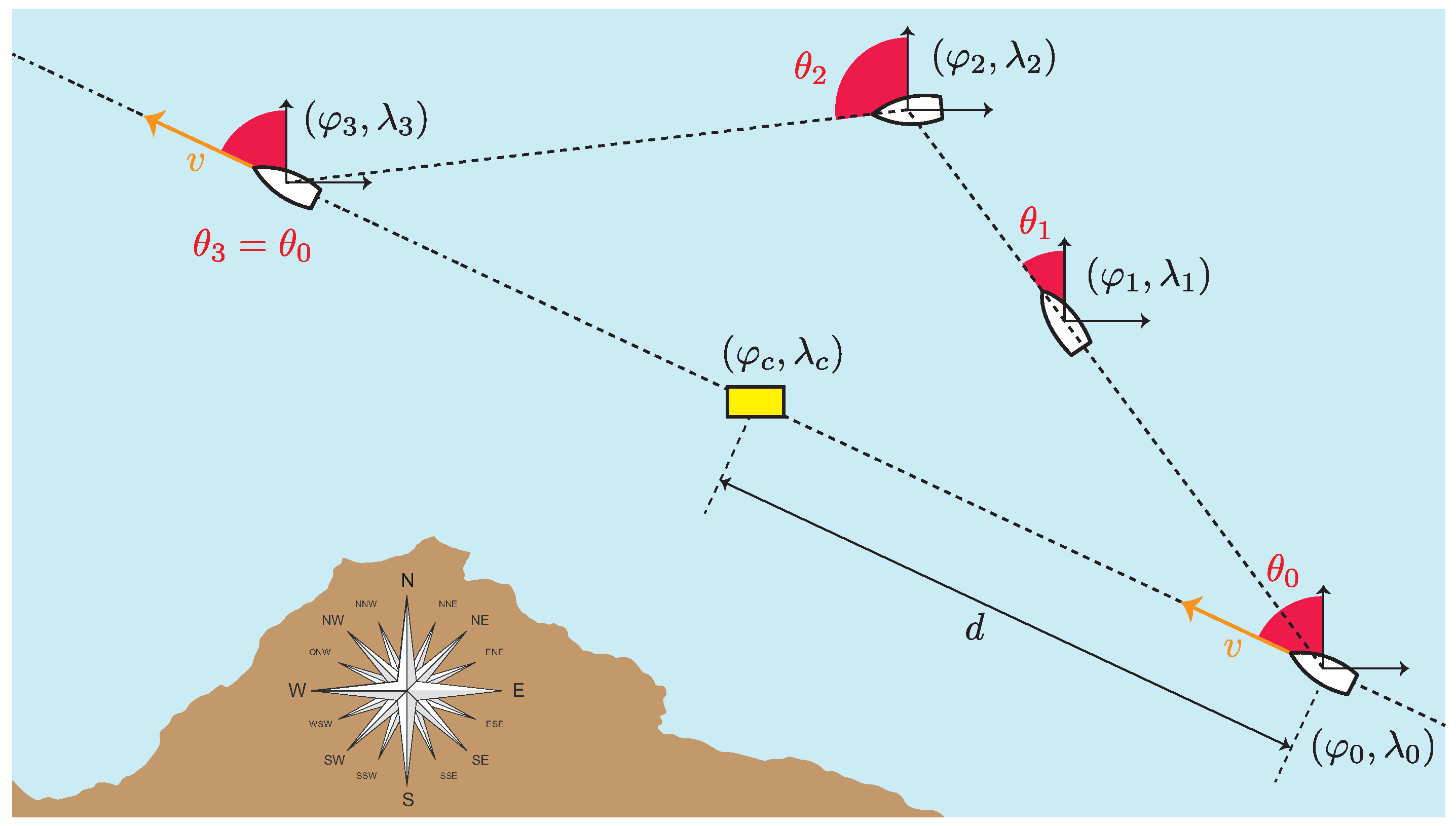
To analyze the performance of these systems, an assumption is made in which a ship, with any collision avoidance system, is sailing in the open sea. At a given instant, the ship is sailing ahead in a straight line at a certain speed,
v, with heading
, being at a latitude and longitude
, respectively. A container is floating in the sea at a position
, and it is assumed that the displacement velocity of the container on the sea surface is much lower than the velocity of the ship, so it can be considered that the container is in a static condition. The position of the container cuts off the trajectory followed by the vessel, so there is a high risk of collision unless the vessel changes course (
Figure 2).
For the vessel to be able to maneuver to avoid a collision, its collision avoidance system must meet the following criteria. Firstly, it must detect the container early enough to be able to carry out an effective diversion maneuver. Secondly, it must be capable of generating an immediate alert upon detection, and finally, it should minimize, as much as possible, the detection of false targets that generate erroneous alarms. In terms of these criteria, the detection range, R, is defined as the maximum distance at which the collision avoidance system would be able to detect a container floating at sea. If the minimum distance between the ship and the container is d, which implies that if the ship is traveling at a speed v it will collide with the container in time t (if there is no change of course), then condition must be fulfilled. Furthermore, the response time, , is defined as the implicit delay of the system to generate an alarm at an instant after having detected the presence of a container floating in the sea at an instant , it being desirable that . The ability for the system to unambiguously detect a container and differentiate it from other elements in the environment is the detection resolution. Thus, sea waves or some anthropogenic elements such as fishing nets or floating plastics could disturb the detection of containers and generate false targets, even though they may not pose a harmful obstacle to navigation. However, other elements such as rocks at the edge of the sea are obstacles that could fracture the hull of the vessel, and the system should be able to detect them even though they are not containers. Finally, the system integrability (the possibility of incorporating the equipment aboard) or economic cost of the system (average price of the equipment) are conditioning factors to integrate these systems onboard.
2.1. Determination Systems
Determination systems include all onboard equipment that generate signals that reach the container and are reflected to the ship. Depending on the nature of the signals transmitted, this group includes radar (Radio Detection and Ranging) and sonar (Sound Navigation and Ranging) systems. Although both systems perform an analogous function, their operation is not performed in the same context. Radars are useful instruments for detecting targets above the water surface, so they could detect containers floating with a part of their fuselage above the waterline)
1 establishes that vessels of less than 150 tons do not require to include a radar as a collision prevention system, but a radar reflector. The radar reflector only allows these vessels to be detected by larger vessels but does not provide smaller vessels with a tool to detect obstacles during navigation. It is important to emphasize that collisions with containers are not a problem for large vessels on international voyages, but for small vessels. Therefore, to underestimate their danger for shipping is to expose most of the global fleet to a danger that can claim human lives. Sonars operate below the waterline, having a significant advantage over radars. Just as a floating container may (or may not) have a part of its fuselage above the water surface, in all cases, it will have another part submerged. Due to this fact, sonar would outperform radar in terms of applicability.
It is considered a marine radar onboard a ship which emits electromagnetic pulses of wavelength
with a transmitted power
by means of a directive antenna with gain
. The pulse is transmitted at time instant
and returns to the radar at time instant
, after reflecting off a container with part of its fuselage above the waterline, which constitutes a target of effective cross-section
. The time difference between the signal emitted and received by the radar,
, will travel twice the distance separating the ship from the container,
R, so that
, where
c is the speed of light. This makes it possible to obtain the distance between the ship and the container from the measurement of
. If the radar has a minimum detectable received power or sensitivity,
, its range will be determined from Equation (
1), known as the radar equation (
Figure 3, above the waterline).
In most cases, containers have metallic structures that facilitate their radar detection. Their effective cross-section is a rectangular cross-sectional area, limited in height by the waterline. The goods inside the containers may move due to damage to the fuselage or wave motion, presenting an inclination on the waterline that would sporadically or constantly modify the effective cross-section of the target, since they affect the greater or lesser sinking of the container. Therefore, the main limitations in radar detection are the performance of the equipment and the conditions imposed by the marine environment, where the presence of an intense swell could block part of the signal transmitted by the radar equipment, generating false targets.
Some commercial models of marine radars are presented in
Table 1. This type of radar is usually installed onboard recreational vessels, such as sailboats or fishing vessels, although their use is not limited to this type of vessel. This table specifies the main characteristics of each commercial model, where the frequency and transmitted power influence the detection range of the equipment, while the beamwidth allows one to know the angular resolution for the detection of targets of a certain size.
Analogous to the radar, sonar generates acoustic pressure waves under the surface of the water, which strike the surrounding objects and return to the equipment in the form of echoes, making it possible to measure the distance at which the objects are located. In the context of the detection of containers at sea, sonars that have a directivity in the forward direction of the vessel are of particular interest. Such sonar is called FLS (Forward-Looking Sonar) [
37] and covers a certain beamwidth in the horizontal and vertical direction that limits detection in both depth and range. This equipment is installed in the boat live work, usually on the keel or other suitable locations where the engines do not disturb detection (
Figure 3, below the waterline).
Let us assume an FLS which emits a pressure level
through the underwater propagation medium. Fixing a reference intensity level,
, the transmitted pressure level depends on the intensity emitted by the device,
, obtaining
. When the acoustic pressure wave travels the underwater medium until it reaches a container located at a distance
d, the level
is reduced on the round-trip path by the channel losses,
, and it is affected by a noise level,
. These losses depend on the distance traveled and the energy absorption to which the underwater medium subjects the acoustic wave, which is characterized by the specific attenuation factor
(expressed in dB/m), so that
[
38]. It should be noted that the device operates close to the waterline, so reverberations,
, that may disturb the underwater transmitted pressure levels will occur. When the transmitted wave reaches a container, there is a relationship between the acoustic energy of the incident,
, and reflected,
, waves, expressed as
. This value depends on the geometry and the manufacturing material of the container. In addition, the device presents a directivity
, which is usually expressed through its vertical and horizontal FOV (Field of View). Finally, Equation (
2), known as the active sonar equation, allows one to determine the minimum pressure level received by the sonar,
[
39,
40].
The commercial FLS models presented in
Table 2 specify the main characteristics of this equipment, where it should be noted that the frontal range is much lower the than typical radar range. This would lead to the reduced maneuverability time of the vessel in cases of detecting a floating container.
2.2. Observation Systems
Observation systems use sensors (cameras) to capture the radiation reflected by objects in the environment, and form images by processing the signals received. Sensors are usually classified according to their mode of operation into passive, if they record reflections of sunlight after hitting the observed objects, and active, if the system has its own source of illumination and records the reflections that occur when illuminating an object [
41]. These sensors are sensitive to a certain range of wavelengths, finding RGB (0.4
m–0.7
m), IR (3
m–5
m), thermal (3
m–14
m), LiDaR (750 nm–1.5
m) and SAR (1 m–10 mm) sensors. In turn, the images formed from these sensors can be panchromatic (a single channel over a wide range of wavelengths), multispectral (several channels over a range of 2 to 13 wavelengths) and hyperspectral (several channels over a range of more than 13 wavelengths) [
42].
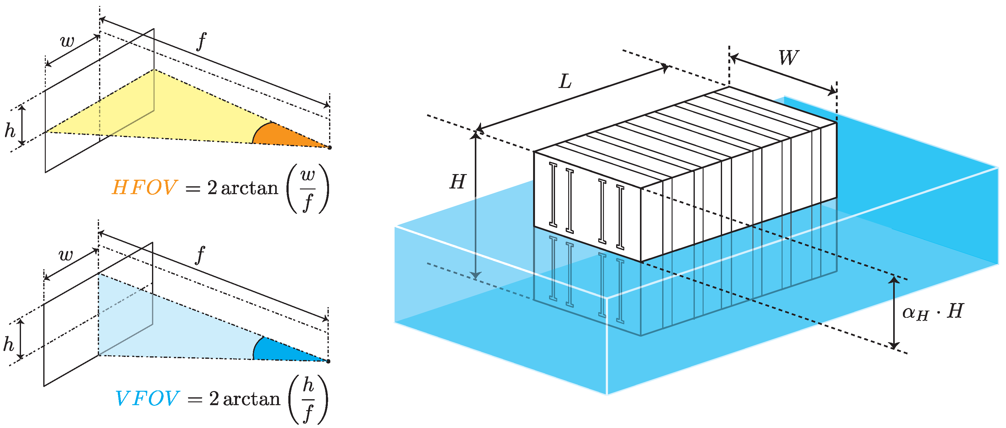
It is assumed that a vessel has an onboard camera to detect the presence of floating objects during navigation. The camera covers a certain range of space directions,
, so a horizontal FOV,
, and vertical FOV,
, are defined to characterize this capability. If the sensor has a focal length
f and a pixel of height
h (vertical) and width
w (horizontal) is generated, then the vertical FOV relates the focal length to the pixel height and the horizontal FOV to its width, as depicted in
Figure 4. It is necessary that the camera can operate under any lighting condition (day or night), so this study is limited to thermal cameras. These cameras detect thermal radiation emitted by objects at a temperature above zero Kelvin or absolute in the mid-infrared range, generating images of
pixels horizontally and
pixels vertically. Therefore, if a camera has a resolution
and, during the navigation, a container located at a distance
d constitutes an obstacle with which it could collide, it is necessary to estimate the maximum distance that must exist between the container and the camera to be detected. In addition, some considerations about the container must be made. First, most containers are made of corrugated steel, although to a lesser extent, some are made of plywood. Second, the ISO-668:2020 standard [
43] establishes container dimensions, with the smallest size being the 20-foot container (2.44 m × 2.6 m × 2.44 m). Finally, the dimensions of the floating container are limited by the waterline in function of the tonnage and arrangement of the goods inside the container, so they must be weighted by factor
in each dimension,
(
Figure 4).
Johnson’s criteria establish the relationship between the minimum resolution of a thermal camera and its detection range [
44]. Thus, the formulated problem will be to determine the number of pixels,
, to record the presence of the container floating for a certain distance with respect to the camera. Adapting Johnson’s criteria to this context, image acquisition would result in three situations. Firstly, detection refers to the ability of the camera to capture the presence of a container, even if it is not possible to distinguish it from a ship or an iceberg, for example. Secondly, recognition allows one to distinguish the container from other types of elements that may be found in the environment (e.g., a ship), establishing a recognition category by types. Finally, identification is associated with the ability to specifically distinguish a container from any other element in the environment, and it can be conceived as an enhancement of the recognition capability.
The number of pixels required for detection is lower than the number of pixels required for recognition and identification. However, it is important to note that the detection of any obstacle during navigation, regardless of whether it is a container or a ship, brings safety to the voyage. Both recognition and identification for collision prevention are desirable, but not strictly necessary. Therefore, only for detection purposes, it is assumed that an image records a height
, expressed in pixels, which corresponds to a height
h, expressed in meters, which will be the actual height of the container. Therefore, it can extract the pixels per meter from the image as
, where the height
h is expressed as a percentage. The FOV is expressed in milliradians,
, as the ratio of the image pixel pitch in micrometers;
is referred to as the distance between the centers of two adjacent pixels; and the focal length is expressed in millimeters,
f, such that
. Thus, Equation (
3) is applied to estimate the maximum sensing distance of the container of height
h.
The commercial marine thermal camera models listed in
Table 3 establish a distance between 0.5 km and 1 km for a person floating in the sea, which would be a lower target than that of the container. Therefore, applying Johnson’s criteria for each of these commercial models on a floating container with
and
, which establishes in-plane dimensions of 0.96 m × 0.96 m for a 20 ft container, establishes 90% probability detection distances of 480 m (M232, Flir), 1330 km (V7, ComNav) and 680 m (Ulysses Micro, Omnisense Systems).
2 3. Monitoring System for Lost Containers at Sea
The systems described in
Section 2 represent a local solution for collision avoidance against floating containers at sea. Although the ability of determination and observation systems to detect this kind of event has been demonstrated, their applicability is limited and unfeasible for global container surveillance. However, if the container integrates a communication system that generates warning signals that are received by ships, not only would collisions be avoided, but also a surveillance network for containers lost at sea would be available. To this end, there are several commercial devices such as Oyster3 (DigitalMatter), CT 3500 (OrbComm), SCT (SigFox) or Contact Wide (SenseFinity) that are capable of communicating information about containers. They are small-sized devices integrated into containers that are capable of operating autonomously for extended periods of time, providing information about the location or status of the containers, which is why they are often referred to as smart containers [
45,
46]. Various authors have investigated the use of different communication systems for container tracking, the main cases being the use of cell phone networks [
47] and satellite communications [
48,
49,
50]. In recent years, the use of spread spectrum communications such as LoRaWAN has provided another communication avenue for container tracking [
51]. Other proposals employ Sigfox [
52], NB-IoT [
53,
54] and even AIS [
55], used in ship-to-ship communications. Thus, the range of communication systems applicable to container tracking may be wide. However, these devices are designed to operate under normal transport conditions. In a loss-at-sea situation, no evidence has been found to guarantee their operability, so the problem must be analyzed.
In contrast to the determination and observation systems analyzed in
Section 2, a communication unit integrated in a container would turn it into an active target, intervening in their own detection, identification and location by radio broadcasting. This implies that a number of criteria must be taken into account. Firstly, as a minimum, transmissions should enable ships to detect containers lost at sea during navigation, although it would also be advisable that, as far as possible, communication with shore stations and satellites could be carried out. Secondly, the device should integrate some type of sensor to activate communications after a container has fallen into the sea. Thirdly, the transmissions must provide relevant information about the container (they must be digital), and also provide the location of the container with the highest accuracy possible. Finally, the device must be compact in size and have an autonomous power supply mechanism that guarantees that the transmissions can be carried out for a period equal to or longer than the time it would take for the container to sink at sea. The above criteria make it necessary to analyze some key aspects of the use of communication systems on containers. Therefore, in the following sections, a specific propagation model for containers lost at sea is proposed, describing the limitations of the different communication technologies used in smart containers in this context. The main characteristics of these communication systems are summarized in
Table 4. Also, the structure of a specific digital message for containers is proposed and the energy consumption of the devices are analyzed in the following sections.
3.1. RF Propagation Model for Floating Containers
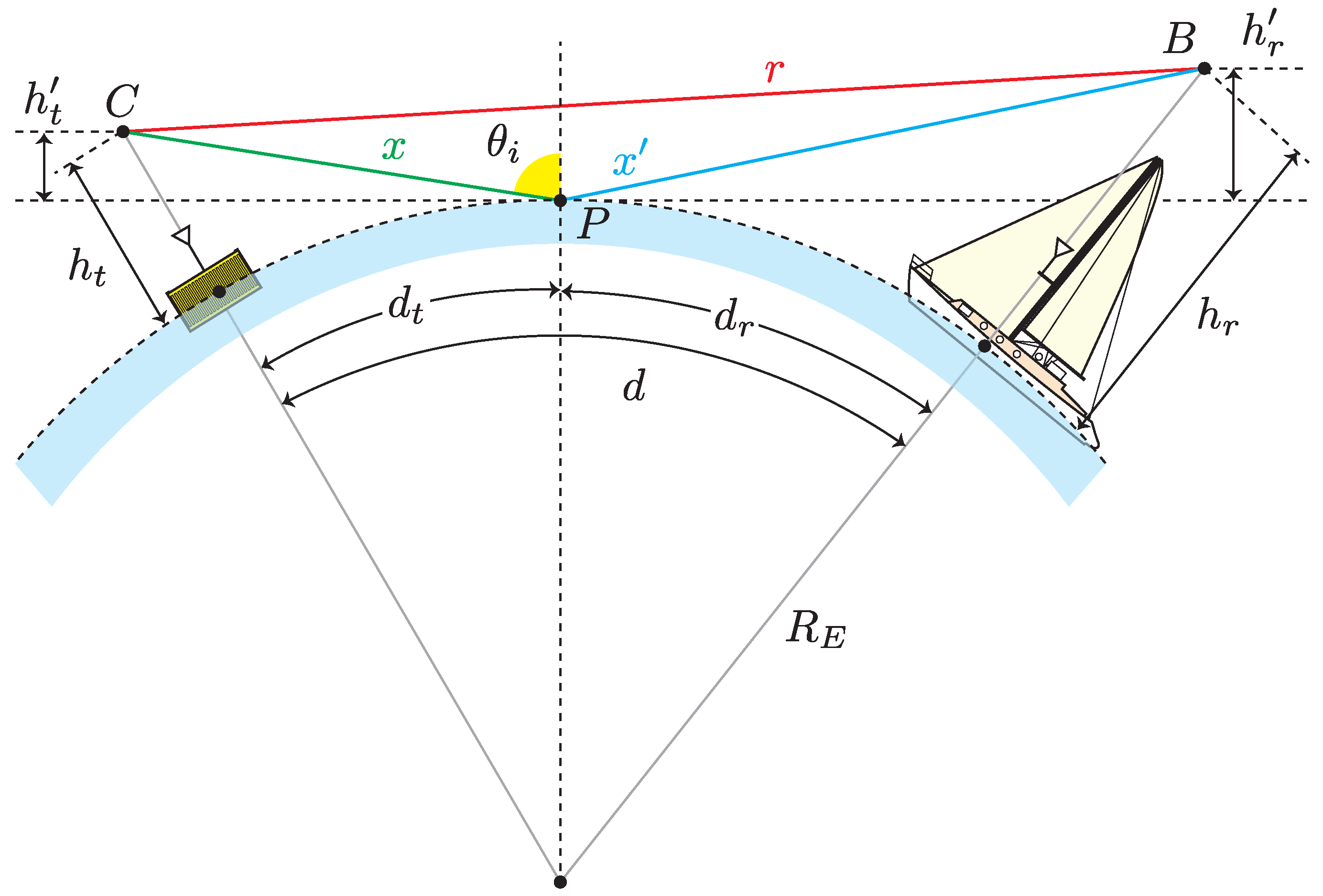
Let us assume a floating container which integrates an RF communication device that operates at
wavelength. The container’s antenna has a gain
and it is located at a height
above sea level. A vessel located at a distance
d of the container detects the emission through an antenna with a gain
and a height
above sea level, and it is assumed that
. When the container signal is transmitted, it will arrive to the vessel through two rays [
56]. The first is the direct ray, which has no obstacles in its propagation, while the second is the reflected ray, which is produced when the signal arrives at a given point of the sea surface. This situation is represented by
Figure 5, when the Earth’s curvature makes it necessary to consider two additional antenna heights,
and
.
During its propagation, the transmitted signal reduces its original power level due to losses,
. If a two-ray model is considered [
57], the losses can be estimated from Equation (
4):
where
R is the reflection coefficient, which will depend on the sea surface features if the sea surface is considered completely flat and a perfect conductor, so
. However, this consideration does not correspond to the reality, because the wind perturbs the sea surface and produces tides. For this reason, the sea surface must be considered a roughness medium which introduces additional signal reflections, so it is necessary to modify the reflection coefficient in terms of the sea roughness. While [
58] models the sea roughness factor as a function of wind, the analysis carried out by [
59] is more widely used to model the RF signal propagation in maritime environments. Thus, a new reflection coefficient,
, is presented, that is expressed by Equation (
5):
where
represents the standard deviation of the sea surface height, and
is the grazing angle of the signal over the sea. This angle can be related to the incident angle,
, through the relation
. In addition to sea roughness, ref. [
60] considers the shadowing effect and signal divergence at the sea surface. The shadowing effect occurs when waves obstruct the signal and produce a shadowing zone that attenuates a factor
S the transmitted signal level, which is modeled by Equation (
6):
where
represents the mean square value of the slope of the wave (generally,
). Along with this attenuation factor, a divergence factor,
, is considered when there is a long distance between the container and the vessel, which causes the signal grazing angles to be very small. This factor weights the reflection coefficient, and is expressed by Equation (
7):
where, according to
Figure 5,
and
are the distances between the reflection point and the antennas of the container and the vessel, respectively, and
is the radius of the Earth. Due to the flattening of the poles,
takes the value 6378.1 km at the Equator and 6356.8 km in polar areas, although its average value is generally taken, which is 6371 km. Therefore, assuming that the gain of each antenna is unitary and considering the intervention of the transmitted and received powers, the losses expressed in Equation (
4) are modified from the effects previously considered, obtaining Equation (
8) to express a general model for signal propagation at the sea surface.
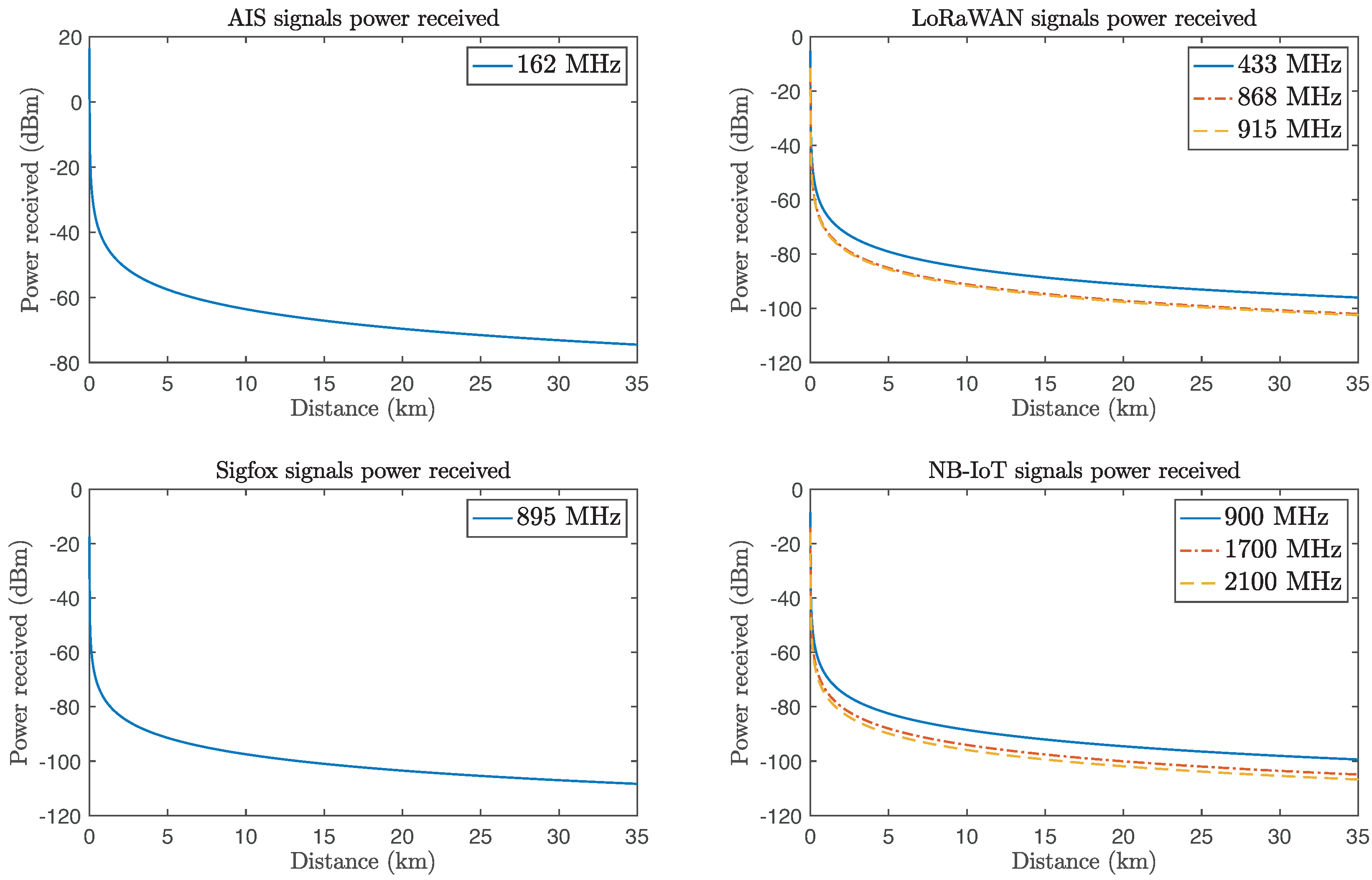
For each communication system indicated at
Table 4, the variation of the power received in terms of the proposed model is shown in
Figure 6. It has been considered a distance of up to 35 km. The antenna heights are
m and
m, and unitary gains are considered. The transmitted power for each system will depend on the levels indicated at
Table 4. The shadowing effect is modeled with a value of
.
Moreover, for all the systems evaluated in
Table 4, the typical sensitivities considered are under the received power levels, so the container–vessel communication could be carried out. A margin
M is defined as the difference between the minimum power level and the sensitivity,
, for all the communication systems analyzed. Thus, AIS communications have a margin of 32.48 dB; LoRaWAN has been evaluated for different frequencies, and its associated margins are 43.9 dB (433 MHz), 37.9 dB (868 MHz) and 37.4 dB (915 MHz); Sigfox has a margin of 33.6 dB, and the margins for different NB-IoT frequencies which have been evaluated are 41.6 dB (900 MHz), 36.1 dB (1.7 GHz) and 34.2 dB (2.1 GHz). These margins are high enough to demonstrate that, even though the height of the communication devices integrated in the containers is small compared to that of the vessels, long communication ranges can be achieved.
3.2. Specific Messages for Containers
Although a container can be detected and even located through its emitted signals, the IoT devices used in this field provide digital information. This would ensure the unique identification of the container, in addition to incorporating other relevant data for monitoring the incident. Some examples are the dimensions of the container, its owner and the cargo it holds. In terms of the information included on the CSC (Convention for Safe Containers) plates of the containers,
Table 5 shows the number of bits required to include each parameter in a telemetry message field. An 8-bit ASCII encoding is assumed, although some of these fields may be optional, such as the dangerous percentage. Other parameters that are usually indicated in the containers, such as volume, can be calculated from the data generated by the message itself, so it would not be necessary to include them.
The proposed message in
Table 5 requires a capacity of 392 bits. This quantity refers exclusively to the payload, so the additional bits that should be added to the message depending on the communication protocol used are not considered.
3.3. Simplified Model of Power Consumption for Containers
Communication devices require a self-contained power supply unit to provide power to the various subsystems which form the device. In general, there are two types of energy sources applicable in this context. On one hand, there are devices that have solar panels, so their power supply will depend on the energy they can capture from the sun during the day, storing it in batteries to operate at night. On the other hand, batteries can guarantee a stable power supply until they run out. Both options require the use of batteries, so this section deals exclusively with autonomous power supply based on the latter. For this purpose, it is assumed that a communication device onboard a container performs periodic transmissions of duration
at time intervals
. When the device transmits a signal, it consumes a current
, and when not, it consumes a current
to keep the other subsystems active, such as the processing unit and sensors (
Figure 7).
If a container falls to the water and its communication device is activated, Equation (
9) describes its average current consumption for a given transmission period.
Therefore, if the battery has a capacity
for a lifetime
, it will allow for a total of
N transmissions before it is completely depleted, as is expressed by Equation (
10).
For example, a LiPo battery (model LP455161) with a capacity of 2000 mAh to power a communication device integrated in a container is considered. The device consumes 100 mA when performing 30 ms duration transmissions every minute, and 10 mA when not transmitting signals. Its average consumption for a transmission period will be
mA. Therefore,
will be the available transmissions which the device can carry out before the battery is totally depleted. This means that the system will be active for 9320 min (6.47 days), which would be sufficient time for it to be detected by ships or satellites. In
Table 6, the same calculations for other battery models have been applied, showing that an increase of 300 mAh in the battery capacity would increase the system activation by almost one day for the
,
and
specifications which have been indicated.
5. Conclusions
The loss of containers at sea has become a serious problem for both marine ecosystems and maritime navigation. The analysis provided in this article points to this type of accident as an important source of pollution that must be minimized, which has the particularity that the degree of pollution they entail for the marine environment depends notably on the type of goods transported. Sufficient references have also been provided to demystify that collisions with containers at sea do not pose a danger to navigation. After reviewing the international legislation on containers lost at sea, it is noted that the need to seek information technologies support to mitigate the effects arising from these catastrophes has not been raised so far. In the absence of technological solutions for these accidents, this article analyzes the applicability of two groups of technologies with potential uses for the detection of containers lost at sea.
Firstly, different performance criteria that determination (radar and FLS) and observation (thermal cameras) systems must meet to allow ships to avoid a collision with floating containers at sea are proposed. The conclusions reached show that these systems could be effective for the local detection of floating containers. It has been indicated how radars would have difficulties in detecting containers with most of their fuselage below the waterline, especially if wave conditions obscure these units and generate false targets. The same is not true for FLS, as containers always have a portion of their fuselage below the waterline and can therefore be detected by such equipment. However, a radar offers a very long range (in the order of 60–80 km), as opposed to the range of an FLS, which is limited to a few hundred meters. Similarly, thermal cameras can reach distances of 1 km, well below the range of radar but beyond that of FLS, although they may be more affected by environmental conditions than radars and FLSs would be.
Secondly, the monitoring systems are associated with communication devices integrated into the containers, which are capable of monitoring these units in case of loss at sea. This solution can be applied to avoid collisions between vessels, but also to carry out remote surveillance of these units when they are lost at sea. For this purpose, some communication systems have been proposed that have been applied in normal conditions of the maritime transport of goods. To emulate their behavior in lost-at-sea conditions, a propagation model has been proposed with which the reception of signals for several communication systems (AIS, LoRaWAN, SigFox and NB-IoT) has been simulated. A digital message structure has also been proposed for container telemetry, where important parameters such as the location or type of transported goods are indicated. A simplified analysis of the power consumption of these units in a loss-at-sea situation is also carried out, showing that they can reach a duration of up to one week with continuous transmissions.
Both determination and observation systems and communication systems have been comparatively analyzed. While the former offer a local solution, the latter allow for continuous monitoring that can be beneficial for tracking and recovery actions at sea. It is important to note, however, that while communication systems may be an alternative that might, at first glance, appear more attractive, the number of containers that are transported on each voyage reduces their applicability to a commercial problem. Each container ship carries an average of 10,000 TEU and, in the case of ULCSs (Ultra Large Container Ships), can exceed 20,000 units. Therefore, an economic analysis is needed to support whether it is feasible to incorporate a communication unit in each container, at least as long as there is no international regulation forcing logistics companies to perform this task.


 ,
, 


