Article

A Novel Hull Girder Design Methodology for Prediction of the Longitudinal Structural Strength of Ships

College of Naval Architecture and Ocean Engineering, Dalian Maritime University, Dalian 116026, China
*
Author to whom correspondence should be addressed.
J. Mar. Sci. Eng. 2024, 12(12), 2368; https://doi.org/10.3390/jmse12122368
Submission received: 24 November 2024 / Revised: 13 December 2024 / Accepted: 19 December 2024 / Published: 23 December 2024
(This article belongs to the Section Ocean Engineering)

Abstract

:
The ship hull girder model has been widely adopted in ship mechanics research such as small-scale and large-scale hydroelastic ship model experiments. Current design methods cannot seriously meet the structural rigidity requirement, and the distinction between the ship structural masses and the cargo masses is rather vague. This research proposes a simple and novel ship hull girder design methodology. The main novelties are that (1) the structural rigidity design requirement for the ship hull girder corresponding to any targeted real ship with arbitrary structural complexity is precisely satisfied by the proposed strategy of adopting a composite hull girder system, and that (2) the mass density per unit length of the proposed hull girder is solely related to the mass density distribution of the targeted ship structures by considering the hull girder system as a complete finite element (FE) model, and thus (3) a better ship hull girder model for prediction of the total structural responses can be consequently established. A real ship is adopted as the design target, and the structural responses of the real ship and the proposed ship hull girder model are compared and analyzed. The proposed model is compared to the currently widely accepted ship hull girder models through numerical experiments. The proposed hull girder design methodology possesses the potential for upgrading the classical structural design approach to match the growing trend of adopting FEM-based approaches for ship structure research.

1. Introduction

Ship structural safety has been an active research focus ever since the beginning of the era of the ship industry in any country around the globe. Structural safety is the prerequisite for the pursuit of outstanding performance in next-gen vessels, such as large container ships [1,2,3] that can carry more containers, ice-breaking vessels [4,5,6] that are capable of bearing harsh ice conditions, etc. In earlier times, the estimation methods for ship structural strength were mainly empirical: based on long-term observations of the characteristics of wave loading on ships and the consequent structural responses, the approach of simplifying the complicated real ship hull as a beam was considered appropriate, gradually culminating in the establishment of the widely adopted classical method [7,8] for the prediction of the total structural strength. The main idea of the classical method was to decompose the total deformation of the ship hull into so-called global longitudinal deformation and local deformation, in which the global longitudinal deformation was calculated based on beam theories [9,10] while the local deformation was analyzed based on plate structure theory [8]. This decomposition methodology made the seemingly impossible task of reliably predicting the total structural responses of complicated real ship hulls easily achievable for ship designers several decades ago when computer capabilities were rather limited.
With the advent of modern computers in the shipbuilding industry, the estimation of ship structural strength has mainly relied on commercial FEM solvers. Based on the FEM theories [11,12,13] and the accumulation of empirical experience in real ship operations, the main classification societies in the world released rules [14,15,16,17,18] for the modeling of ship structures based on FEM theories. Although the released rules contain guidance on full length structural strength analysis based on global FE modeling of the whole ship structure, the hull girder strength estimation methodology still prevails in those rules due to the effectiveness and efficiency of such simplification for most loading conditions. A global FE analysis that covers the whole ship structure may be required for ships with large deck openings subjected to severe oblique sea conditions that cause overall torsional deformation [17]. In addition, the hull girder strength estimation approach is more suitable for the preliminary structural design of a new ship. Therefore, it is still safe to say that the key idea of the classical method still dominates in many areas of ship structural strength estimation in the ship industry, and it can be anticipated that improvements to the classical method may quickly have an impact on ship engineering.
In recent years, researchers have adopted the FE modeling method as well as other notable computational mechanics methods to solve the pressing challenges raised in ship mechanics. Zhao et al. [19] proposed a computational framework to simulate ship–ice-ridge interactions. The local bow structure of the original icebreaker, modeled by FE elements, was chosen as the sub-structural model for the demonstration of the proposed framework. Jiao et al. [20] presented a partitioned CFD-FEM two-way coupled numerical tool to investigate asymmetric water entry problems for local bow and stern structures. A wedged grillage structure modeled by FEM represents the local bow or stern structures. Jiao et al. [21] adopted a coupled CFD-FEA method to predict slamming and green water loads on a containership sailing in regular waves, where the scale ratio for the numerical standard S175 type containership model was 1:40. The scaled numerical containership was modeled as a hull girder whose vertical bending stiffness was assumed to be constant, and the first-order natural frequency of vertical bending vibration for the numerical hull girder satisfied the requirement of the principle of similarity [22]. Hu et al. [23] studied the ductile fracture of stiffened ship hull plates during ship stranding by using the meshfree Reproducing Kernel Particle Method (RKPM) [24,25], where the stiffened plates were locally extracted from the ship bottom of the global ship hull. Liu et al. [26] conducted a numerical and experimental investigation on the collision of the hull structure at local stiffened plates. In particular, the real ship collision accident was modeled as inclined penetration of the local stiffened plate extracted from the ship hull. Heo et al. [27] adopted peridynamics to study the buckling behavior of local cracked plates of ship hulls. Aiming at investigating the influence of brittle crack growth on the strength of ship structures, Nguyen and Oterkus [28] adopted a peridynamic shell model [29] to simulate brittle crack propagation in an experimental MST4 ship model [30], which now could be viewed as a segment of a ship hull near the middle cross-section. The above research efforts reveal that the decomposition approach to the aforementioned classical method still plays a vital role in ship mechanics investigations.
This research is aimed at improving the classical method, which may lead to a quick impact on the ship industry. In contrast to the wide attention paid to calculating the local responses at specific ship hull spots, this research carefully studies the methodology of establishing the ship hull girder model for a better understanding of the global longitudinal structural responses within the classical method. We found some of the main drawbacks of the existing methods and accordingly proposed a method to model the complicated real ship hull that overcomes those shortcomings. The immediate influence of the proposed method is probably on the scaled hydroelastic ship model experiment technology which heavily relies on the quality of the elastic ship model hull girder. Based on the proposed ship hull girder design methodology, we further upgrade the classical method to more consistently match the trend of adopting FEM for ship structural strength estimation. In addition, we quantitatively analyze the error between the structural responses obtained by the improved classical method and the full three-dimensional FE modeling method, which is also scarce in the literature.
This paper is organized into eight sections. In Section 2, we present briefly the theory of the Euler–Bernoulli beam, which is the main theory adopted in the classical method, and then analyze the main shortcomings of the full application of beam theory in ship structural mechanics. The process of establishing the new ship hull girder system that overcomes the aforementioned drawbacks of the existing beam theory is detailed in Section 3, culminating in the upgrade of the classical method, which is presented in Section 4. The basic verification of the newly proposed hull girder system design method is detailed in Section 5. Section 6 introduces the necessary establishing details of a full-scale hull girder system based on a targeted real ship, with a comprehensive comparison of the ship structural responses obtained from the real ship FE model and the full-scale hull girder FE model. To further prove the necessity of the proposed design method, in Section 7, the longitudinal global structural responses of two currently widely accepted backbone-type ship hull girder models are compared with those calculated by the proposed ship hull girder model. We close the presentation in Section 8 with a discussion and conclusion.

2. Euler–Bernoulli Beam Theory and Its Applications

2.1. The Euler–Bernoulli Beam Theory

The Euler–Bernoulli beam theory has been widely adopted in ship mechanics. This beam theory requires the real ship hull to be slender so that the ship hull can be formulated as a slender beam without the influence of shear force and moment of inertia. The forced vibration equation of an Euler–Bernoulli beam [31] is as follows:
2 x 2 E I x 2 y x 2 + m x 2 y t 2 = P x , t
where E is Young’s modulus, which is assumed to be constant along the beam. I(x) is the second moment of area of the cross-section at longitudinal position x of the beam, and m(x) is the mass of the beam per unit length. P(x,t) is the dynamic external loading per unit length at time t. Equation (1) can be fully expanded as follows:
E 2 I x x 2 2 y x 2 + 2 E I x x 3 y x 3 + E I x 4 y x 4 + m x 2 y t 2 = P x , t
If I(x) is assumed to be constant, then Equations (1) and (2) can be simplified as
E I 4 y x 4 + m x 2 y t 2 = P x , t
If m(x) in Equation (3) is further assumed to be constant, then, based on Equation (3), the natural vibration frequencies of the beam with simply supported ends can be analytically derived as [31]
ω n = n π L 2 E I m   ,   n = 1 , 2 , 3 ,
where ωn denotes the n-th order natural vibration frequency and L is the length of the beam. If the second moment of area I(x) or the mass density m(x) is not constant, then obtaining the natural vibration frequencies of the beam through analytical approaches becomes very difficult. Consequently, the transfer matrix method [32] is widely adopted to numerically calculate the natural vibration frequencies and the corresponding vibrational modes.

2.2. Ship Global Longitudinal Strength Estimation

One of the applications of the Euler–Bernoulli beam theory is to estimate the global longitudinal strength of real ships. In this application, the real ship hull is simplified to a full-scale Euler–Bernoulli beam. This simplification is not achieved by literally creating a full-scale beam model that corresponds to the original real ship hull, but by assuming that the original real ship hull responds to external loading according to the same mechanism as the Euler–Bernoulli beam. Once the cross-sectional vertical bending moment M(x,t) is obtained, the global longitudinal response of the real ship hull can be immediately calculated using the following simple formula [8]:
σ x , t = M x , t z I x
where σ(x,t) is the global normal stress at time t at cross-section x, z is the vertical position of the structural component at the cross-section relative to the neutral axis, and I(x) is the second moment of area of the cross-section x. After acquiring the global longitudinal structural responses of ships, the total structural response of any structural component of ships is assumed to be the sum of the global longitudinal response and the local response, which forms the core of both the classical and modern ship structural analysis methods. Therefore, the first application of the Euler–Bernoulli beam theory in ship mechanics can be concluded as laying the foundation for ship structural analysis.
However, shortcomings related to this application of the Euler–Bernoulli beam theory can be identified. The assumption that the real ship hull itself can be directly considered as an Euler–Bernoulli beam presents a problem: this ship hull beam cannot be accurately modeled by adopting any FE modeling software. If the hull beam were to be constructed with an FE simulation tool, the beam in question would be the whole original real ship hull itself, which is not our intention in the first place. Therefore, the application mentioned above lacks a truly full-scale Euler–Bernoulli beam model for the targeted real ship hull, which will be referred to as the “independent hull girder” in this research. The experimental hydroelastic ship hull girder is in fact designed to test the properties of the independent hull girder described above. The absence of such an independent hull girder model for the targeted real ship results in the experimental data from the hydroelastic ship model tests providing only indirect insights into the global longitudinal structural responses of the targeted real ship hull.

2.3. Design of Scaled Hydroelastic Ship Models

Since the real ship hull itself does not have a corresponding full-scale beam model, referred to as an independent hull girder model, the design of a realistic beam model that is related to the real ship hull is actually conducted within the framework of scaled segmented hydroelastic ship model experiments. In these experiments, the scaled experimental ship hull girder is designed to satisfy the principles of similarity regarding cross-sectional rigidity and mass density. The principle of similarity, derived from the Euler–Bernoulli beam theory, is expressed as follows [22]:
E 1 I 1 X L 1 5 = E 2 I 2 x L 2 5 m 1 s X L 1 2 = m 2 s x L 2 2 ,   m 1 c X L 1 2 = m 2 c x L 2 2 Z G s 1 X L 1 = Z G s 2 x L 2 ,   Z G c 1 X L 1 = Z G c 2 x L 2 X = λ x
where subscripts 1 and 2 denote the targeted real ship and the scaled experimental ship model, respectively, and subscripts s and c denote the ship structures and the cargo, respectively. The subscript G denotes the cross-sectional center of gravity (COG). X and x are the longitudinal coordinates locating the longitudinal positions of cross-sections of the targeted real ship hull and the scaled experimental ship hull girder model, respectively. λ is the so-called scaling ratio of the experimental ship model. E denotes the Young’s modulus, I denotes the cross-sectional second moment of area, L denotes the length perpendiculars, and m denotes mass per unit length. ZGs1(X) denotes the vertical position of the COG at cross-section X of the targeted real ship hull, with other similar terms denoting the counterparts for the scaled ship model.
The strict requirements outlined in Equation (6) are difficult to achieve for both small-scale and large-scale hydroelastic experimental ship models using existing design methods. An alternative design principle, adopted as a compromise, modified the first equation of Equation (6) to focus on the similarity of the first three orders of natural frequencies [33,34,35,36,37,38,39,40,41,42,43]. The second and third equations were adjusted to ensure the similarity of the positions of the COG of the final overall rigid ship. This compromise design principle does not detail the longitudinal mass distribution and additionally necessitates the similarity of the overall longitudinal moment of inertia. It has been discovered that with current techniques, only the similarity requirement for the first-order natural frequency can be satisfactorily met, thereby further reducing the precision of this alternative principle compared to Equation (6).
Another shortcoming of the aforementioned alternative principle to Equation (6) is the difficulty in strictly distinguishing the masses of the ship structures from those of the cargo. In most previous hydroelastic ship models, the length of the hull girder was significantly shorter than that of the rigid ship shell, indicating that much of the ship structural masses were actually replaced by non-structural masses. Therefore, for ships carrying large tonnages of cargo, such an experimental design may introduce uncertain effects on the final experimental outcomes. It is clear that the substantial weight of the cargo is a kind of static external loading on the ship structures and does not contribute to resisting ship structural deformation, and therefore, it should be considered separately.

3. A Novel Hull Girder Design Methodology

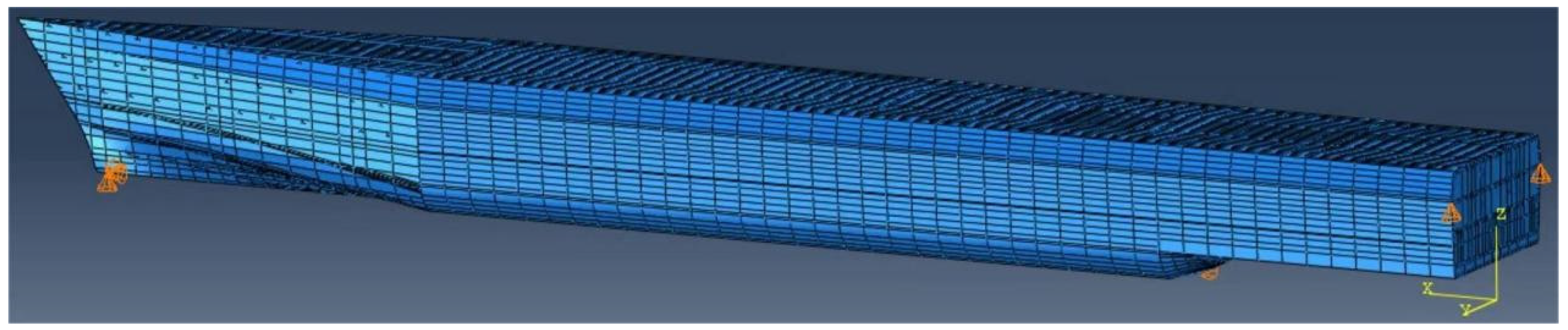
This research proposes a novel design methodology for the ship hull girder of its targeted real ship, addressing the aforementioned inherent shortcomings of existing methods. This new design approach presents a full-scale FE beam model for its targeted real ship hull. Not only can this model be used to directly analyze the global longitudinal structural responses of the real ship, but it also provides direct guidance for the design of hydroelastic experimental ship hull girders that strictly satisfy Equation (6). Furthermore, this new design methodology could lead to an upgrade of the classical ship structural estimation method, aligning the upgraded method with the modern development trends in computational ship structural mechanics.

3.1. Design of Ship Hull Girder Components

The proposed new ship hull girder design method is founded on the basic premise that the targeted real ship hull can be modeled as a system of Euler–Bernoulli beams. By setting L1 = L2 and λ = 1 in Equation (6), the corresponding design principle for the full-scale ship hull girder of the real ship hull is
E 1 I 1 x = E 2 I 2 x m 1 s x = m 2 s x ,   m 1 c x = m 2 c x Z G s 1 X = Z G s 2 x ,   Z G c 1 X = Z G c 2 x
As mentioned in Section 2.3, achieving strict similarity in structural rigidity is challenging [33,34,35,36,37,38,39,40,41,42,
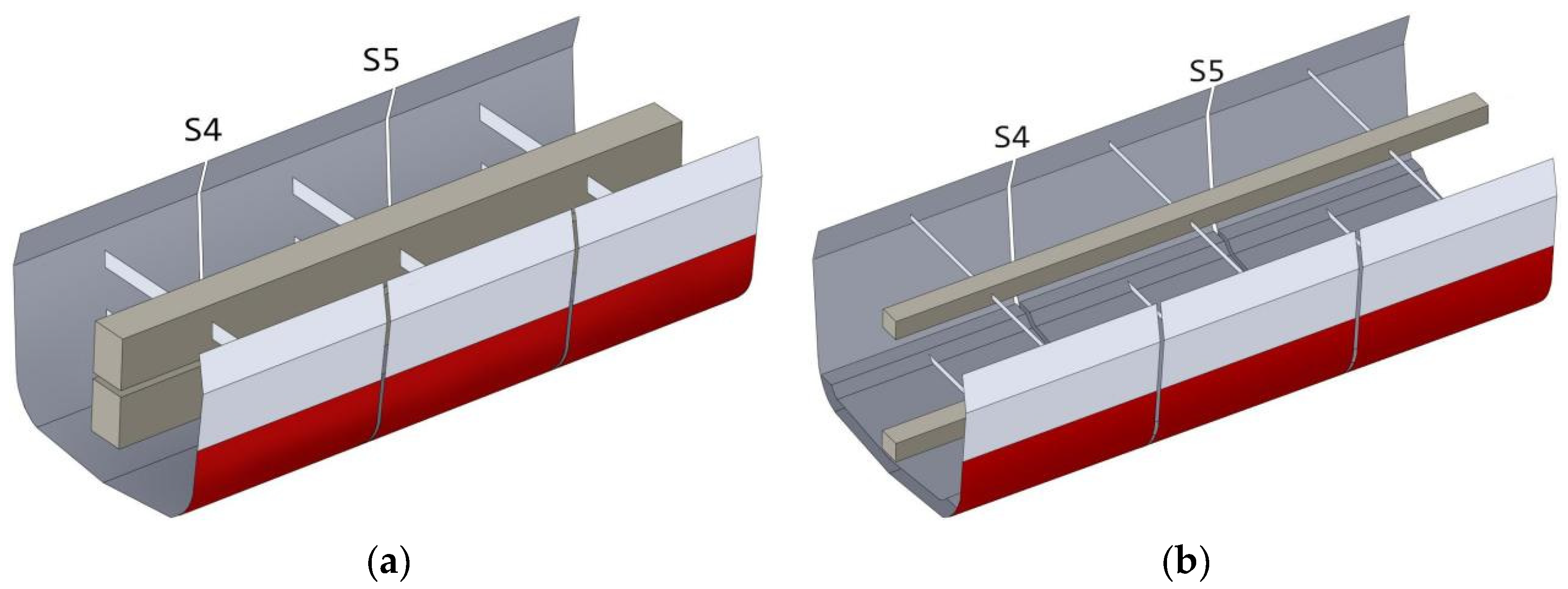
43]. Designing the cross-sectional rigidity of a full-scale hull girder for the real ship using existing methods is more difficult than designing a scaled hull girder for the same real ship. For a scaled hull girder, the cross-sectional rigidity is scaled to be much smaller, which significantly reduces the difficulty of the design task. This research proposes a new hull girder design approach that combines the Euler–Bernoulli beam theory with the FE modeling techniques and employs a two-step strategy to strictly meet the design principles outlined in Equation (7). The resulting full-scale hull girder is essentially an FE model system, primarily composed of deformable hull girders and undeformable segmented outer ship shells, akin to the familiar segmented hydroelastic ship model. These undeformable segmented outer ship shells serve as the medium for applying external loading to the ship, causing the hull girders to deform as a result of the external loading on the shells.
The first step of the new design approach is to satisfy the mass density requirement specified in Equation (7) while distinguishing between the masses of the ship structure and the cargo. With reference to Equation (7), the mass per unit volume ρ2(x) and area A2(x) of the cross-section x of the full-scale ship hull girder can be determined as follows:
ρ 2 x = i = 1 N x ρ 1 i x N x A 2 x = m 1 s x ρ 2 x
where ρ1i(x) denotes the mass per unit volume of the i-th ship structural material on cross-section x of the targeted real ship hull and N(x) is the number of structural components on cross-section x. Equation (8) ensures that the newly designed ship hull girder corresponds solely to the targeted real ship structures, without accounting for the cargo. The vertical position of the COG of A2(x), denoted as ZGs2(x), must be equal to ZGs1(x), as required by Equation (7). This requirement will be addressed later, once the exact geometry of A2(x) is determined.
The second step of the proposed method is to satisfy the cross-sectional rigidity requirement specified in Equation (7). If the full-scale beam is assumed to be a single rectangular beam, as is the case with existing methods, then the cross-section x of the beam model in question satisfies the following equations:
b x h x 3 12 = E 1 I 1 x E 2 b x h x = A 2 x Z G s 2 x = h x 2 = Z G s 1 x
where b(x) and h(x) are the width and the height of the cross-section of the single rectangular beam, respectively. Equation (9) is thus in fact an over-determined system for the height h(x). Substituting the first equation into the second equation of Equation (9) yields
h x = 12 E 1 I 1 x E 2 A 2 x h x = 2 Z G s 2 x
The first equation of Equation (10) may not be compatible with the second, which poses a central problem for the existing methods. This issue stems from the stereotypical assumption that the ship hull girder must always be a single rectangular beam. The proposed new design approach, also within the Euler–Bernoulli beam theoretic framework, allows the ship hull girder system to be composed of multiple beams along the vertical direction of the cross-section for the targeted real ship. The sub-cross-section of each beam component can take any one of the following common shapes: a triangle, a rectangle, or a trapezium. For any type of real ship, this newly proposed hull girder system of multiple beams always exists: the interior region of each cross-section (from the outer boundary of the cross-section inwards, excluding the outer boundary of the upper deck) is guaranteed to provide sufficient space to accommodate these multiple beams with desired geometrical shapes, provided the cross-section is a hollow, composite plate structure, regardless of its structural complexity. Note that the number of the beam components should not exceed 3, considering that the effect of the local response of the final full-scale hull girder system should be kept negligible.
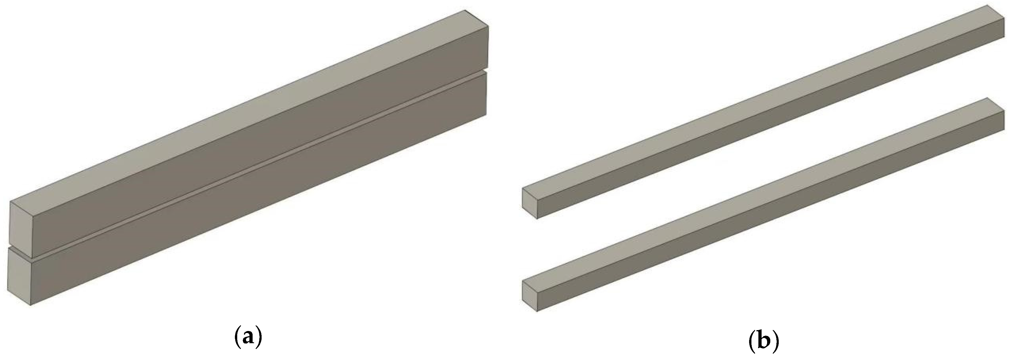
To illustrate, we first present a two-rectangular-beam hull girder system using the proposed hull girder design methodology. The upper beam is labeled U, and the lower beam is labeled D. The width and height of the upper beam are denoted as wU(x) and hU(x), respectively, while those of the lower beam are denoted as wD(x) and hD(x), respectively. If such a two-rectangular-beam system exists, then it must be determined by the following equations:
w U x h U x + w D x h D x = A 2 x I U 0 x + I D 0 x + w U x h U x d U x 2 + w D x h D x d D x 2 = E 1 I 1 ( x ) E 2 w U x h U x Z G s 1 x + d U x + w D x h D x Z G s 1 x d D x = Z G s 1 x A 2 x
where IU0(x) and ID0(x) denote the second moments of area of the cross-sections relative to their respective neutral axes for the upper beam U and the lower beam D, respectively. dU(x) and dD(x) denote the parallel distances between the neutral axis of the entire cross-section and the neutral axes of the upper and lower beam cross-sections, respectively. Equation (11) is thus an under-determined system. One feasible approach to obtain a unique solution from Equation (11) is to introduce the following three additional equations:
w U x h U x = β x w D x h D x w U x = α U x h U x w D x = α D x h D x
where β(x), αU(x), and αD(x) are coefficients that determine the detailed cross-sectional geometry of the two beams. The values of these three coefficients are specified by the users. In general, Equations (11) and (12) provide a unique solution for a two-rectangular-beam system, which serves as the full-scale ship hull girder for many kinds of targeted real ships.
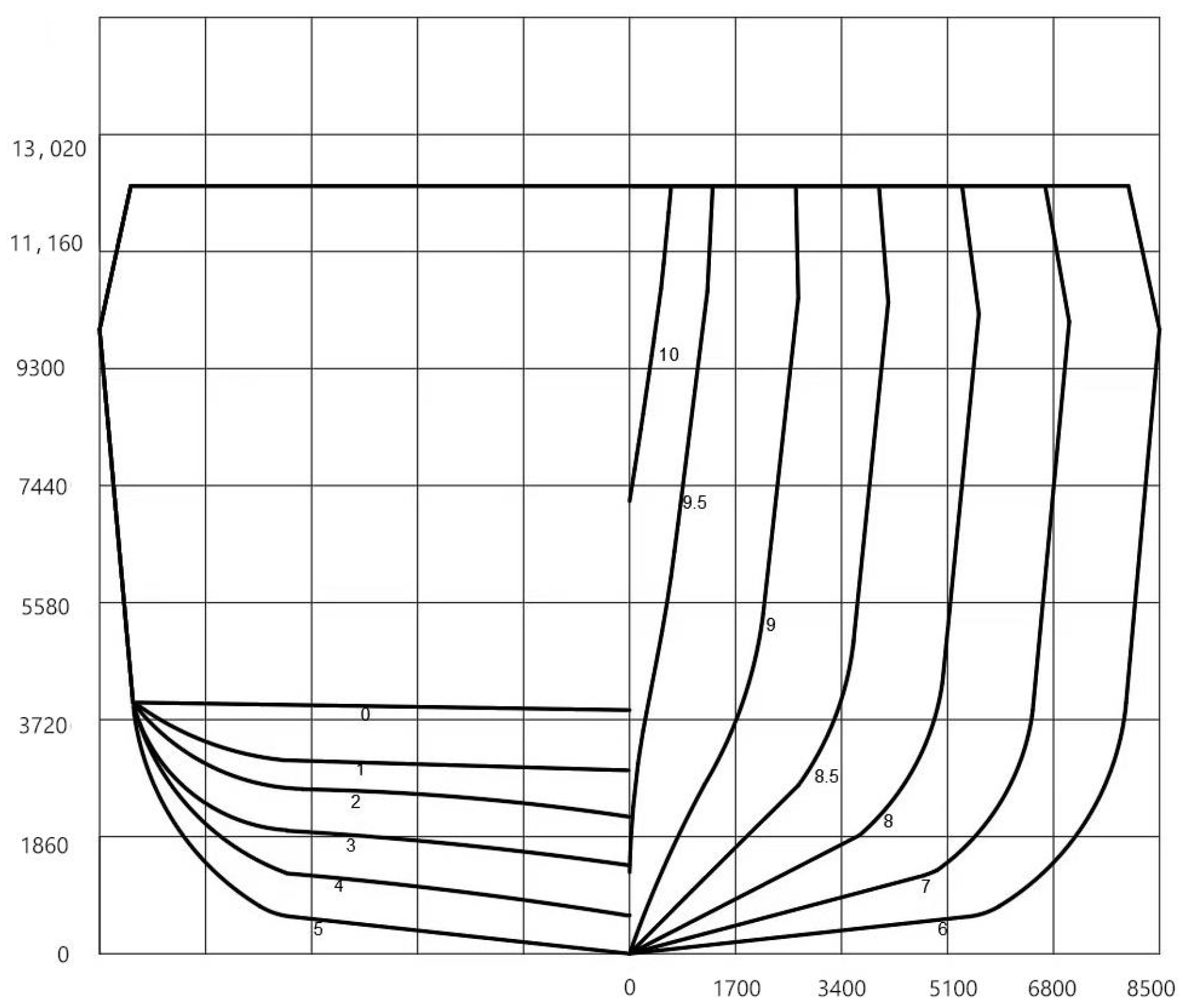
A general composite hull girder system design can be obtained by generalizing the previously introduced two-rectangular-beam system design. For generality, consider a cross-section extracted from the bow region of a real ship, which has a shape that is a smooth combination of a triangle and a bulb. The bottleneck-shaped smooth transition region is assumed to be quite narrow. The geometrical characteristics of this chosen cross-section are representative of the bow region for ships with a pronounced bulbous bow structure. Similar to the meshing technique in FEM, the upper single beam Ω is assumed to be an isosceles trapezoidal beam, while the lower beams form a double-isosceles-trapezoidal-beam system, ensuring a satisfactory hull girder cross-section model of the chosen real ship’s overall cross-section. The upper and lower isosceles trapeziums of the lower beam system are denoted as B and C, respectively. The distances from the top side of the overall cross-section to the upper and lower parallel sides of Ω are denoted as dΩu and dΩl, respectively, where the subscripts u and l denote the upper and lower parallel sides, respectively. The distances from the bottom base line of the overall cross-section to the upper and lower parallel sides of B are denoted as dBu and dBl, respectively, with the corresponding distances for C denoted as dCu and dCl. The design principles are then precisely expressed by the following equations:
A Ω + A B + A C = A 2 z Ω A Ω + z B A B + z C A C = Z G s 1 A 2 E 2 I Ω 0 + I B 0 + I C 0 + A Ω T Ω 2 + A B T B 2 + A C T C 2 = E 1 I 1
where symbol A denotes the area, symbol z denotes the vertical position of the neutral axis, symbol I denotes the second moment of area, and symbol T denotes the parallel distances between the neutral axis of the overall cross-section of the real ship and the neutral axis of the sub-cross-section of a beam component. The subscript 0 refers to the neutral axis of the sub-cross-section of a beam component. The meaning of any term in Equation (13) can be directly and easily understood by the readers; for example, the composite symbol AΩ denotes the cross-sectional area of beam Ω. To ensure that Equation (13) yields a unique solution, the following complementary equations should first be added:
A Ω = 1 2 W Ω u + W Ω l d Ω l d Ω u A B = 1 2 W B u + W B l d B u d B l A C = 1 2 W C u + W C l d C u d C l z Ω = H h Ω e d Ω u z B = d B u h B e z C = d C u h C e I Ω 0 = d Ω l d Ω u 3 W Ω u 2 + W Ω l 2 + 4 W Ω u W Ω l 36 W Ω u + W Ω l I B 0 = d B u d B l 3 W B u 2 + W B l 2 + 4 W B u W B l 36 W B u + W B l I C 0 = d C u d C l 3 W C u 2 + W C l 2 + 4 W C u W C l 36 W C u + W C l T Ω = z Ω Z G s 1 T B = z B Z G s 1 T C = z C Z G s 1
which in fact just explicitly define every term in Equation (13) for the chosen shapes of the beam components. The composite symbol hΩe denotes the vertical distance from the COG of beam Ω to its own upper parallel side; hBe, the vertical distance for beam B; and hCe, the vertical distance for beam C. H denotes the overall height of the overall cross-section, which is a known parameter. The symbol W in Equation (14) denotes the length of any parallel side of a trapezium. Then, the meaning of any term in Equation (14) can accordingly be directly inferred by the readers; for example, WΩu and WΩl denote the lengths of the upper and lower parallel sides of beam Ω, respectively. To complete Equations (13) and (14), the following constraint equations are required:
W Ω u R 2 d Ω u tan θ W Ω l R 2 d Ω l tan θ W B u Q B u W B l Q B l W C u Q C u W C l Q C l W Ω u W Ω l 2 tan α Ω = d Ω l d Ω u W B u W B l 2 tan α B = d B u d B l W C l W C u 2 tan α C = d C u d C l
where R denotes the length of the uppermost base of the overall cross-section and θ denotes the angle between the uppermost base and its neighboring leg. R and θ are known parameters of the overall cross-section. The symbol α denotes the angle between the leg and the longer parallel side of an isosceles trapezoidal beam component. αΩ, αB, and αC are thus also known parameters for those isosceles trapeziums, adjusted by users during the design or solution processes. The length of each quantity associated with the W-symbol in Equation (15) is then prescribed by the local largest width of the overall cross-section, denoted by each Q-symbol-associated quantity, which is known a priori. This ensures that the finally obtained beam system is positioned totally within the geometrical boundary of the overall cross-section. It is evident that by combining Equations (13)–(15), a unique design of the composite beam system can be achieved, which precisely meets the design principles expressed by Equation (7).
Equations (13)–(15) are recommended to be solved using the “progressive searching” method rather than seeking a purely analytical solution. This recommendation stems from the first six inequalities in Equation (15), each of which describes the general characteristics of its corresponding W-symbol quantity. The progressive searching method provides users with the flexibility to apply these six inequalities to various overall cross-sections that may be encountered. Once the W-symbol quantities, along with the corresponding d-symbol quantities, are found to satisfy the remaining equations within the united equations, the desired solution for the sub-cross-sections corresponding to the beam components is finally obtained.
Note that, even for the simpler case of a two-rectangular-beam system described by Equations (11) and (12), a progressive searching approach is also necessary. Users have to experiment with different values for αU, αD, and β to find a solution for the two-rectangular-beam system. This case is considered simpler because, once the three basic parameters are suitably selected, dU and dD can be analytically solved using Equations (11) and (12). Consequently, by integrating the design techniques for both a two-rectangular-beam model and a more complex composite beam model, a comprehensive full-scale ship hull girder system can be developed for any type of targeted real ship.
It has been further observed that both the two-rectangular-beam and the composite beam cases discussed above serve as examples within a general ship hull girder design framework. The primary design procedures are as follows: (1) presenting the expressions of the structural requirements, (2) providing interpretations for each term in the first procedure, and (3) providing supplementary geometrical constraints. Note that the deck is not considered part of the boundary of the original ship cross-section, which implies that the resulting beam component may extend beyond the upper deck, as will be detailed in subsequent sections of this research. The generalized design framework thus affords designers the greatest flexibility in establishing an appropriate ship hull girder system. The solution procedures for the composite hull girder system are demonstrated in Figure 1.

3.2. Formulation of Hull Girder FE Model

This sub-section continues to demonstrate how to complement the new ship hull girder system with the outer ship shell to ultimately form a complete FE model capable of predicting the global longitudinal structural responses of the targeted real ship. Each hull beam component is modeled using a collection of three-dimensional hexahedral meshes. The entire outer ship shell is modeled as a rigid shell based on the table of offsets of the targeted real ship. The mass of the rigid ship shell is set to be extremely small to minimize its effect on the mass distribution of the final complete FE model. The original intact rigid ship shell is divided into several disjoint segments by removing a number of slim slices evenly distributed along the longitudinal direction of the rigid ship shell. Within each ship shell segment, the narrow middle regions of each beam component are rigidly fixed by massless rigid supports extending from the center of the rigid ship shell segment. The rigid ship shell segments are designed to directly withstand the distributed dynamic wave loading pressures from the surrounding fluid, and the rigid supports will transmit the external wave pressures to all of the beam components through the beam fixing regions. The number of segmented rigid ship shells and the size of the fixing middle region of the beams need to be determined appropriately, drawing on previous designs of scaled hydroelastic experimental segmented ship models for relevant reference [33,34,35,36,37,38,39,40,41,42,43].
Now it comes to the treatment of cargo masses included both in Equations (6) and (7). The original real ship cargo holds will be modeled as nearly massless rigid model cargo holds, which are then placed within the established FE model at the same locations as the original cargo holds in the targeted real ship. The cargo masses, distributed within the original cargo holds, are equivalently modeled as static loading distributed across the bottom areas of the modeled rigid cargo holds. This treatment not only restores the effect of cargo masses on the ship structures but also maintains the original spatial distribution characteristics of those cargo masses in the targeted real ship. Thus, it is expected that during the design stage of a new ship, the impact of cargo mass distribution on the final ship structural responses can now be directly studied using the proposed new ship hull girder model.

4. Upgrade to Structural Strength Estimation Method

The classical ship structural strength estimation method decomposes the total deformation of a structural component into the global longitudinal deformation and the local deformation. The global longitudinal deformation is calculated based on beam theories, which also assume that every cross-section of the beam remains flat throughout the deformation duration—a concept known as the flat cross-section assumption [8]—that lays the foundation for classical ship structure mechanics. In fact, the flat cross-section assumption is not essential in the classical ship structural strength estimation method, because the key idea is to decompose the total deformation of a structural component while ensuring that the computational models for the global longitudinal and local deformation calculations are directly related to the original targeted ship. A hull girder system whose cross-sectional rigidity and mass density are equivalent to those of the original targeted ship is sufficient to serve as the computational model for calculation of the global longitudinal deformation. Beam theories based on the flat cross-section assumption actually impose additional restrictions on the characteristics of shear force, requiring that the shear stresses be constant along every cross-section. The proposed new ship hull girder is modeled by the three-dimensional hexahedral elements which will not be prescribed by the flat cross-section assumption, thus broadening the application of the decomposition methodology. Thus, the classical structural strength estimation method can now be upgraded by the proposed ship hull girder model as follows:
For ships sailing in head seas, the total deformation of any structural component can be decomposed into the so-called global longitudinal deformation and the local deformation. The global deformation can be calculated using a composite ship hull girder model, avoiding issues inherent in the classical Euler–Bernoulli beam model. Meanwhile, the local deformation can be determined from the local FE model of the local real ship hull structure.
This newly upgraded version of the classical ship structural strength estimation method is anticipated to become a new additional tool for design of ship structures, complementing the available empirical formulas provided in the rules and guidance issued by international ship classification societies.

5. Verification of the Proposed Design Method

An overall cross-section containing a bulbous region was extracted from a 64,000 DWT bulk carrier, and the proposed ship hull girder cross-section design method was applied to this selected overall cross-section to demonstrate its effectiveness. It is difficult for existing popular design methods to design a beam that seriously satisfies such cross-sectional structural design requirements, particularly for bulbous-shaped cross-sections where the width at the narrowest point approaches zero. The structural details of the selected cross-section are depicted in Figure 2a, with the main parameters detailed in Table 1. By applying Equations (13)–(15) to this overall cross-section using the progressive searching method, a relatively simple solution is obtained, and the main parameters of the beam cross-sections are listed in Table 2. The resulting beam sub-cross-sections are two identical isosceles trapeziums. The presence of these trapezoidal beam sub-cross-sections thus confirms the effectiveness of the proposed beam cross-section design methodology. We also try to apply Equations (11) and (12) to this overall cross-section using an analytic approach, and it is discovered that for this selected overall cross-section, a two-rectangular-beam solution also exists, with the obtained rectangular beams being identical. We list their main parameters in Table 3. The existence of such a two-rectangular-beam solution suggests the broad application potential of Equations (11) and (12) in bow region cross-sections of real ships.

6. Application to a Real Ship

To further comprehensively test the applicability of the proposed ship hull girder design method, a real ship was selected as the subject for designing its full-scale ship hull girder system, which is required to precisely satisfy Equation (7). The selected real ship lacks a bulbous structure in its bow region, so the design principles of Equations (11) and (12) should suffice to formulate its hull girder system. Although the bow region of the real ship lacks a bulbous structure, the narrow triangular shape of those bow area cross-sections presents a relatively significant design difficulty, thus preserving the requirement for generality in selecting such a real ship.

6.1. Formulation of Full-Scale Ship Hull Girder

The main particulars of the targeted real ship are detailed in Table 4, and the principal material properties of the ship structures are detailed in Table 5. The body plan of the targeted real ship is depicted in Figure 3, where the unit lengths of the horizontal and vertical grids are 1700 mm and 1860 mm, respectively. The two-rectangular-beam cross-section design methodology outlined in Equations (11) and (12) is adopted to perform the construction of a full-scale ship hull girder system for the targeted real ship. The mass densities per unit length and cross-sectional second moments of area for both the real ship and its full-scale ship hull girder system are compared in Figure 4a,b. Figure 4 reveals that the proposed design method successfully presents a full-scale ship hull girder system with an overall length that exactly matches the length of the targeted real ship, and the mass densities and second moments of area of the selected cross-sections are identical to those of the targeted real ship. Furthermore, as shown in Figure 5a, the resulting full-scale ship hull girder system features hull girders with variable cross-sections along the length of the ship. To the best of the authors’ knowledge, this type of full-scale ship hull girder has not been realized previously in the literature. This example, therefore, confirms the applicability of the proposed ship hull girder system design methodology.
Figure 5 presents the process of developing a complete FE model for the full-scale ship hull girder system, starting from the bare beams and ending with a model to which the realistic three-dimensional wave loading can be applied. The process involves using an appropriate number of fixing brackets that rigidly connect the outer segmented ship shells to their spatially corresponding ship hull beam components, as depicted in Figure 5b,c. Figure 5c shows an example where the number of segmented ship shells is set to 10, resulting in 9 cross-sections labeled from s1 to s9, which extend from bow to stern and are prepared to serve as the focus for detailed study on the structural responses.

6.2. Comparison of Cargo Modeling Methods

The Euler–Bernoulli beam approach for establishing ship hull girders cannot distinguish between ship structural masses and cargo masses. This sub-section quantitatively analyzes the effects of different cargo modeling methods on the structural responses of simple beams extracted from the established hull girder system. A recent version of ABAQUS software (www.3ds.com/products/simulia/abaqus, accessed on 18 December 2024) has been adopted to perform the structural modeling and analysis tasks in this research. For simplicity, and without loss of generality, the three segments containing cross-sections s4 and s5 within the parallel middle body of the targeted real ship are selected for analysis, and two full-scale hull girder segment models are created based on the newly proposed design method. The mass density per unit length for any arbitrary cross-section of the first hull girder model is designed to be the sum of the mass densities of the ship’s cross-section structures and the cargo. In contrast, the second hull girder model is designed solely based on the ship structures, with the cargo weight modeled as a static loading, as shown in Figure 6. The cross-sectional rigidity of the first hull girder model is maintained the same as that of the second. The pure weight of the ship structures of the selected part is 1217.71 t, and the weight of the cargo is designed to be 4083.29 t. The cargo mass is designed to be over three times that of the ship structural mass to account for possible large cargo loading conditions. Figure 7 presents the final FE models for the two full-scale hull girder segments. Note that the second hull girder segment is just extracted from the entire full-scale ship hull girder model introduced in the previous sub-section. We further specify that the cargo is loaded on the inner bottom plates along the three segments; therefore, in the second hull girder FE model, the rigid inner bottom plates on which the static cargo loading is applied are constructed, as demonstrated in Figure 7b. The basic physical parameters of the first hull girder segment are listed in Table 6.
The wave loads on the two FE models are chosen to be the transient bottom slamming loads. The applied transient bottom slamming loads are calculated based on an empirical formula in [44] (in Section 5 of Chapter 4, Section 1 of Volume 9):
P S L = 10 g L f S L c S L _ e t
where coefficients fSL and cSL_et are determined based on their corresponding empirical formulas, which are presented in [44] but are omitted here for brevity. The loading duration is set to be 0.93 s. The structural responses of the two FE models under the applied transient bottom slamming loads are calculated using ABAQUS software (www.3ds.com/products/simulia/abaqus, accessed on 18 December 2024), and the peak vertical bending moments (VBMs) and peak vertical shear forces (VSFs) at s4 and s5 are extracted from the two FE models for comparison, as presented in Table 7. The two different FE models result in evidently different peak values of VBM and VSF at the same cross-section. This is due to the well-known fact in FEM that different FE models, when subjected to the same loading, will yield different structural responses. This example thus implies the significance of the proposed ship hull girder design methodology.

6.3. Comparison of Structural Responses

This sub-section systematically compares the VBMs and longitudinal total bending stresses of the established hull girder system FE model with its corresponding targeted real ship FE model under a deliberately designed empirical regular wave loading condition. The aforementioned longitudinal bending stress refers to the normal stress component σ11, whose direction of the unit normal vector is parallel to the longitudinal direction of the ship. The targeted real ship FE model is constructed according to the instructions presented in [44], as illustrated in Figure 8 (the orange symbols in Figure 8 indicate the locations where displacement boundary conditions are established). Both the real ship FE model and the proposed ship hull girder FE model are assumed to withstand an empirical regular wave. The loading characteristics are designed as follows: based on [44] (in Section 5 of Chapter 4, Section 1 of Volume 9), the total wave loading pressure Pex is the sum of the static water pressure PS and dynamic periodic wave pressure PW. Empirical formulas are provided for determining each pressure component, but they are not presented here for brevity. We further assume that the wet surface of the ship is its mean wet surface, and the wave length is equal to the length of the water line of the ship. To capture the dynamic characteristics of wave loading without loss of simplicity and generality, the initial phase distribution of the dynamic periodic wave pressure along the longitudinal direction of the ship is depicted in Figure 9: The purple part denotes the mean wet surface, and the gray part denotes the freeboard. The red stepping zone represents negative initial phases, while the cyan stepping zone represents positive initial phases, and the magnitude of each stepping column denotes the uniform magnitudes of the initial phases of those dynamic wave pressures within that column. The progressive dynamic wave pressures PW(x,y,z,t) = PW(x,y,z)cos(ωt + ε) along the longitudinal direction of the ship can be established (where PW(x,y,z) is the pressure amplitude at location (x,y,z), ω is the circular frequency equal to that of the designed regular wave, and ε is the designed initial phase as illustrated in Figure 9). The distribution of the designed initial phases along the real ship is determined by assuming that the initial maximum dynamic wave pressures are in the middle of the real ship, as shown in Figure 9. This deliberately designed wave loading can thus be seen as the Froude–Krylov-type loading, which appropriately considers the effects of radiation loading and diffraction loading [45,46,47], since the empirical formula [44] expressing the amplitude of the dynamic wave pressure includes all corresponding practical requirements necessary. The structural responses of the two FE models under several wave periodical loading periods are calculated using ABAQUS software (www.3ds.com/products/simulia/abaqus, accessed on 18 December 2024), and relatively stationary structural responses are selected for comparison. To eliminate the effect of rigid body motion in the ABAQUS analysis process (www.3ds.com/products/simulia/abaqus, accessed on 18 December 2024), some locations in the FE model of the targeted real ship are constrained according to the guidance in [44], as shown in Figure 8.
Figure 10 compares the cross-sectional VBM between the hull girder FE model and its targeted real ship FE model. VBM plays a vital role, particularly in hydroelastic segmented ship model experiments. For both existing ship hull girder models and this newly proposed ship hull girder model, VBM is the only physical quantity that can be directly compared with the corresponding targeted real ship. Figure 10 reveals that for the selected targeted real ship, the cross-sectional VBMs of most sections near the middle of the ship are well approximated by the newly proposed ship hull girder model. Specifically, cross-sections from s3 to s6 exhibit a reasonably good agreement of VBMs obtained from both the real ship and the ship hull girder FE models, with the smallest and biggest relative errors for VBM extreme values being less than 3% and around 20%, respectively. For cross-sections s2 and s7, the VBM troughs obtained by the two models are in good agreement, although the VBM peaks differ evidently. Cross-sections s1, s8, and s9 show pretty large differences in VBM peaks and troughs, particularly for cross-section s9, where the biggest relative error for VBM extreme value exceeds 100%. This indicates that for the chosen targeted real ship under a middle sea state, the newly proposed ship hull girder FE model is unable to produce reliable VBM predictions for the bow and stern regions.
For the proposed ship hull girder FE model, the total stress response for a given structural component is the sum of the longitudinal beam bending stress, calculated from the VBM obtained by the hull girder FE model, and the local stress obtained from the local real ship structural FE model, which is extracted from the entire real ship FE model. As an example, Figure 11 illustrates the local real ship structural FE model for calculating the total stress in cross-section s5. This model is extracted from the complete real ship FE model, with its geometrical center at cross-section s5 and its length exactly equal to the length of each ship segment. Two locations on each cross-section of the ship are selected for comparing stress results obtained by the two models: one on the deck plate and the other location on the bottom plate, as shown in Figure 12. Figure 13 mainly focuses on comparing the total stress responses obtained directly from the real ship FE model and indirectly through the newly proposed ship hull girder system FE model. The total stresses obtained based on the proposed ship hull girder FE model should now be considered as the total stresses obtained by the updated ship structural strength estimation method. Figure 13 also presents the pure beam stress responses obtained through the proposed ship hull girder FE model. In general, Figure 13 shows that (i) the precision of the total stresses from the updated ship structural strength estimation method varies not only from cross-section to cross-section but also from location to location and (ii) the beam stress component accounts for the predominant share of the total stress. Specifically, cross-sections s2, s3, s4, s5, s6, and s8 have only one structural location where the total stresses calculated by the two different models agree satisfactorily, while s7, adjacent to both s6 and s8, shows larger relative errors for most extreme total stresses at both locations. The deck location shows better agreement of extreme total stresses than the bottom location for s4, s5, and s6, whereas the opposite phenomenon is observed for s2 and s8. The case for cross-section s3 is more complex; the deck location shows better agreement for the troughs of the total stresses than the peaks, while the bottom location shows the exact opposite phenomenon. The results of the pure beam stress component in Figure 13 show that the local stress component can be seen as a minor modification to the pure beam stress component. Among all locations, only the bottom plate location in cross-section s1 has a local stress component whose contribution to the total stress is evident. This demonstrates that the hydroelastic ship model experiment is indeed a reliable research approach for obtaining total stress within the framework of the existing and updated ship structural strength estimation methods. Pronounced discrepancies in the total stresses, such as those at the bottom locations in s4 and s5, reflect the shortcoming of fully applying the flat cross-section assumption to every ship structural component. By comparing Figure 10d with Figure 13h, and Figure 10e with Figure 13j, it is evident that the vertical stress distributions along s4 and s5 are not entirely linear as predicted by the flat cross-section assumption, with the two bottom locations being the exceptions. In other words, the three-dimensional effect inevitably exists in some locations of the real ship. The bow and the stern regions show pronounced discrepancies in total stresses simulated by the two models, implying that the updated ship structural strength estimation method fails in these regions. This fact, similar to the previous VBM case in this sub-section, cautions against the widespread application of the classical ship structural strength estimation methodology in bow and stern regions. Figure 13 thus suggests that the classical ship structural strength estimation method needs to be further complemented with a deliberate modification strategy to provide satisfactory total structural responses predictions, particularly in the bow and stern regions. Proposing plausible modification strategies is temporarily outside the scope of this research. The newly proposed ship hull girder FE model, for the first time, quantifies the precision of the classical ship structural strength estimation method, thus paving the way for further enhancement strategies.

7. Comparison of Different Design Methods

The necessity of the proposed ship hull girder design method might be questioned due to the fact that in ship industry and ocean engineering applications, the design of both full-scale ship structures and scaled experimental hydroelastic ship models does not seem to be a problem. For example, in the design task of scaled experimental hydroelastic ship models, practical codes and fast-running computing algorithms based on the aforementioned transfer matrix method have been widely adopted. Additionally, designers can design the usual scaled ship hull girder using any commercial FEM software. So, it is reasonable to question the need for efforts to propose new methods for obtaining full-scale or scaled ship hull girders. This sub-section aims to demonstrate the necessity of the proposed ship hull girder design method by comparing it with the currently existing methods.
We use the same real ship discussed in previous sections as the target ship for designing several full-scale ship hull girders. The first full-scale ship hull girder is designed as a single rectangular beam with uniform cross-sections, while the second is designed as a single rectangular beam with non-uniform cross-sections. These two kinds of ship hull girders predominate in previous scaled ship hydroelastic experiments [21,37,39,40,42]. As this research focuses directly on full-scale ships, these two hull girder models are designed to be full-scale. Thus, these two full-scale hull girder models can be seen as the full-scale counterparts of their corresponding indoor tank experimental hull girder models. These two kinds of ship hull girders belong to the widely adopted category of backbone-type ship hull girders. Compared with the full-elastic ship model, the backbone-type ship model is much easier to design and manufacture. As discussed in Section 2.3, the backbone-type ship model does not necessarily need to satisfy the strict structural design principle described by Equations (6) or (7), and the design efforts center on the following parameters: the natural frequencies, the position of COG, and the moment of inertia. Thus, both the uniform and non-uniform backbones can serve as candidates for the expected ship model hull girder. An important property of both the uniform and non-uniform backbones is that the length of the backbone can be adjusted to match the overall arrangement of the whole ship model. For example, for the self-propelled hydroelastic experimental ship models, the large stern area of the ship model does not contain the backbone for the sake of arranging the propelling system [39,40,42]. In this section, the length of the uniform backbone is designed to be half the total length of the targeted real ship, while the length of the non-uniform backbone is designed to be over 0.6 times the total length of the real ship, as shown in Figure 14c,f. Note that, theoretically speaking, the backbone-type ship model is a partial elastic model because this model is composed of an elastic backbone and several rigid ship shell segments. When such a ship model vibrates under dynamic wave loading, its response is partially elastic and partially rigid: the backbone as a whole vibrates elastically, while the rigid ship shell segment which does not contain the backbone rotates rigidly. In other words, the structural vibration details of such backbone-type ship models are different from their targeted real ships. In the following content, the effect of this difference will be manifested.
As mentioned, compared with the proposed design method, the classical design method for obtaining the two backbone ship models is less time-efficient. The classical design task is essentially an optimization problem with three objectives: (i) natural frequency, (ii) the position of COG, and (iii) the moment of inertia. These three objectives are interdependent. In contrast, the proposed method offers clear and straightforward procedures, with the primary design freedom being the shape of the cross-sections. Note that the non-uniform backbone here is designed with an additional requirement as follows:
I n I n + 1 = I n I n + 1
In Equation (17), In denotes the second moment of area for the n-th cross-section of the non-uniform backbone ship model, with n ranging from 1 to 6, corresponding to each interval between two adjacent rigid ship shell segments, as shown in Figure 14d. In denotes the corresponding cross-sectional second moment of area for the targeted real ship. Equation (17) thus ensures that the longitudinal distribution of cross-sectional rigidity in the non-uniform backbone is similar to that of the targeted real ship.
The main parameters for the two backbone-type ship models are listed in Table 8. The first-order natural frequencies of the two backbone models are designed to closely match those of the targeted real ship, with a relative error of 4.1% for the uniform backbone model and 2.7% for the non-uniform backbone model. The second-order natural frequencies for the two backbone models are also very close to those of the real ship, with relative errors of 2.6% and 6.5%, respectively. The relative errors for the moments of inertia of the two backbone models do not exceed 3.0%. The relative errors for the position of the COG of the two backbone models are kept within 5%. Therefore, according to the classical design principles, the two backbone models can be used to predict the VBM responses of the targeted real ship. For clarity, the two backbone-type hull girders and ship models are illustrated in Figure 14. The vibrational modes for both the ship models and the targeted real ship are illustrated in Figure 15.
It is mentioned that Table 8 does not present the main parameters for the ship model designed using the proposed method, nor does Figure 15 illustrate the corresponding vibrational modes. The reasons are as follows: (i) the FEM based numerical method cannot be used to obtain the vibrational characteristics of the proposed ship model, which has a hull girder system composed of vertically separated beams, because the method provides vibrational characteristics for individual beams rather than the beam system as a whole; (ii) if practical codes based on the transfer matrix method are used, the obtained vibrational characteristics for the proposed ship model will be identical to those of the targeted real ship, as the cross-sectional characteristics of the proposed ship model exactly match those of the targeted real ship. So, here in Table 8 and Figure 15, only the two backbone-type ship models are involved for demonstration.
It is also noted here that the effect of the added mass of water on the vibrational characteristics of the ships is not considered here for the following reasons: (1) In a scaled hydroelastic segmented ship model experiment, calculating vibrational properties that consider the added mass of water is necessary, as it is much more convenient to verify the ship model’s vibrational characteristics in water. (2) As explained in the preface of Section 6, this research entirely focuses on the full-scale ship hull girder model. The FE analysis, which focuses on the so-called dry vibrational modes without considering the effect of the added mass of water, is deemed sufficient. Furthermore, dry vibrational modes are widely adopted in the theoretical hydroelastic analysis method, as exemplified by the theoretical method presented in [48].
As shown in Figure 15f, the second-order vertical global vibrational mode of the targeted real ship exhibits evident local vibrational modes in certain areas of the upper deck. The real ship, composed of many adjacently linked plate structures, will exhibit local and global vertical bending modes simultaneously if the natural frequency of the second-order vertical global vibrational mode is close to the natural frequencies of some local structures within the real ship. This is also why the vibrational characteristics of the proposed vertically separate beam system should not be calculated using commercial FEM software, as it can only provide the vibrational characteristics of each separate beam. In addition, it is difficult to identify the third-order global vertical vibrational mode of the targeted real ship because the local vibrational mode predominates at such high frequency. Therefore, only the first two orders of vibrational characteristics of the targeted real ship are extracted to serve as the design targets for the two backbone-type ship models.
The VBMs at cross-sections s2 to s6, calculated by different full-scale ship hull girder models under the same external wave loads introduced in the previous section, are simultaneously compared to the results obtained from the targeted real ship, as illustrated in Figure 16. The present hull girder system is denoted as the “new beam” in Figure 16, and it is evident that the present hull girder system provides the most satisfactory VBM calculation results. However, evident deviations from the VBM results of the targeted real ship can also be found for the present ship hull girder model. From cross-section s3 onwards, the two backbone models both generate dynamic VBM responses whose phases are evidently different from those of the dynamic VBM responses of the targeted real ship. This phase difference between the backbone model and the targeted real ship is rooted in the fundamental structural characteristics of such backbone models: models whose length of the backbone is evidently smaller than the total length of the ship model will generate vibrations evidently different from their targeted real ships. This is because the structures along the whole length of the targeted real ship are entirely elastic, while in contrast, the presented two backbone-type ship models are in fact only partially elastic. The present newly proposed design method generates a ship hull girder system whose length is the same as its targeted real ship, thus making the whole ship model entirely elastic. Here, the meaning of the present ship model being entirely elastic should be interpreted as follows: there is no pure rigid body rotation along the length of the newly proposed ship model.
It should be mentioned here that all the full-scale ship hull girder models adopted are established in the simplest possible manner, without any practical modifications such as an exquisite arrangement of mass distribution. Thus, the purpose of Figure 16 is not to challenge the currently widely accepted whole design procedures for the two widely accepted backbone-type segmented ship models. Rather, it aims to show that if the simplest manipulation of hull girders is compared, the new method may provide a simpler solution to the preliminary design of a targeted full-scale ship and the design of a whole scaled experimental hydroelastic ship model, requiring fewer practical modifications.

8. Discussion and Conclusions

Achieving full similarity in mass density and cross-sectional rigidity for model-scale ship hull girders has been a challenge. Hydroelastic ship model designers have to compromise, ensuring at least that the first-order natural frequency of the ship model is similar to that of the targeted real ship. The full-scale ship hull girder even has not been materialized yet; it only exists conceptually. This is because the difficulty in designing a full-scale ship hull girder is larger than that associated with the design of scaled ship hull girders, as previously thought. The scaling of the cross-sectional rigidity actually reduces the difficulty of finding a model-scale beam using the classical design methodology.
This research proposes a new methodology for designing a full-scale ship hull girder for any type of targeted real ship, capable of fully satisfying the requirements on mass density and cross-sectional rigidity, thus completely resolving the aforementioned longstanding problems. In addition, the proposed method precisely separates the mass of the cargo from the mass of the pure ship structure, something that is not possible with the currently existing methods. The proposed method can be directly applied to the design of scaled hydroelastic ship model beams, as the design principles remain the same. A real ship is selected as the target for the design of the full-scale ship hull girder, and the proposed method produces a full-scale ship hull girder that satisfies all relevant requirements. In fact, the newly proposed design methodology allows for multiple solutions to exist, meaning that the specific geometries of full-scale ship hull girder are not unique, thus providing designers with multiple options. Based on the newly proposed design methodology, the classical ship structural strength estimation method has been updated.
The design of the ship hull girder is not the final goal but a necessary step towards comprehensive ship structural strength estimation. Comparing VBM and total stresses between the ship hull girder FE model, established based on the newly proposed design methodology, and the targeted real ship FE model shows that, in general, the VBM obtained by the ship hull girder FE model is more reliable than the total stresses. This finding thus confirms the research on structural strength based on the ship model test approach, as in that approach, the measured quantity for comparison is the VBM. The precision of the total stresses predicted by the proposed ship hull girder varies both from cross-section to cross-section and from location to location at a single cross-section. This reveals that for the selected targeted real ship and many other similar real ships, the flat cross-section assumption works well for many cross-sections as demonstrated by the precision of the obtained VBM. However, the flat-cross-section-based beam stress calculation may result in significant error. This is because the original three-dimensional effects of the established ship hull girder FE model, although not evident in many cross-sections when considering VBM, will manifest at some locations on the three-dimensional beam system, which will be inevitably captured by the total stress. Both the VBM and total stress comparison results show that the ship hull girder method fails to produce reliable total structural response predictions in the bow and stern regions of the chosen targeted real ship, thus cautioning the currently widely accepted simulation method for obtaining total structural responses in those regions.
From the perspective of theoretical mechanics, the currently widely accepted backbone-type hull girder ship models are partially elastic and partially rigid. Specifically, the backbone zone of the ship model, which is composed of both the backbone and the rigid ship shells, is elastic. Other regions that do not contain the backbone, such as the bow region and the stern region, are rigid because the rigid ship shells only move in a rigid manner. So, the goal of the compromise design principle is to make the global vibration of this half-elastic, half-rigid ship model similar to its targeted real ship by adjusting the parameters of the first one or two natural frequencies, the position of COG, and the total moment of inertia. However, such a model cannot automatically fully recover the details of structural responses of the targeted real ship, which is fundamentally a fully elastic structure. In contrast, the present proposed design method aims to generate a ship hull girder model that can almost capture the details of structural responses of the real ship by seriously satisfying the original design principle on cross-sectional rigidity and mass density. Compared to the currently widely accepted backbone-type ship hull girders, the present proposed ship hull girder should provide a simpler solution for the design of a scaled segmented ship model with fewer practical modifications.
The proposed ship hull girder design methodology, for the first time, makes the classical ship structural strength estimation method quantifiable and falsifiable, thus paving the way for its future improvement. This research is a theoretical study on the design methodology for a ship hull girder system, and the future research plan is to further test the proposed method through experiments.

Author Contributions

Conceptualization, H.Y. (Haicheng Yu); methodology, H.Y. (Haicheng Yu); software, S.W., Y.Z., W.L. and H.Y. (Haiyi Yang); validation, H.Y. (Haicheng Yu) and S.W.; formal analysis, H.Y. (Haicheng Yu); investigation, H.Y. (Haicheng Yu) and S.W.; resources, H.Y. (Haicheng Yu); data curation, S.W. and Y.Z.; writing—original draft preparation, H.Y. (Haicheng Yu) and S.W.; writing—review and editing, H.Y. (Haicheng Yu) and S.W.; visualization, S.W.; supervision, H.Y. (Haicheng Yu); project administration, H.Y. (Haicheng Yu); funding acquisition, H.Y. (Haicheng Yu). All authors have read and agreed to the published version of the manuscript.

Funding

This research is partially supported by the Fundamental Research Funds for the Central Universities (No. 3132022118), and this support is gratefully appreciated.

Institutional Review Board Statement

Not applicable.

Informed Consent Statement

Not applicable.

Data Availability Statement

Some data are contained within the article, and complete data can be requested from the authors.

Conflicts of Interest

The authors declare no conflicts of interest.

References

  1. Feng, Q.D.; Wen, L.J.; Jiang, C.X.; Wang, X.L. Springing loads analysis of large-scale container ships in regular waves. Qual. Reliab. Eng. Int. 2024, 40, 2959–2975. [Google Scholar] [CrossRef]
  2. Wang, Q.; Yu, P.; Chang, X.; Fan, G.; He, G. Research on the bow-flared slamming load identification method of a large container ship. Ocean Eng. 2022, 266, 113142. [Google Scholar] [CrossRef]
  3. Lee, D.H.; Paik, J.K. Ultimate strength characteristics of as-built ultra-large containership hull structures under combined vertical bending and torsion. Ships Offshore Struct. 2021, 15, S143–S160. [Google Scholar] [CrossRef]
  4. Jeon, S.; Kim, Y. Fatigue damage estimation of icebreaker ARAON colliding with level ice. Ocean Eng. 2022, 257, 111707. [Google Scholar] [CrossRef]
  5. Han, K.; Zhang, Y.; Ye, L.; Guo, C.; Wang, C. Experimental research on propeller-ice contact process and prediction of extreme ice load. Ocean Eng. 2023, 287, 115912. [Google Scholar] [CrossRef]
  6. Yu, Y.; Zhao, D.; Li, C.; Liang, Y.; Wang, Z.; Sun, W. Research on ship-ice collision model and ship-bow fatigue failure mechanism based on elastic-plastic ice constitutive relation. Ocean Eng. 2024, 306, 118005. [Google Scholar] [CrossRef]
  7. Xie, Y.; Wu, J.; Li, J. Design of Ship Structures; Shanghai Jiao Tong University Press: Shanghai, China, 2011. (In Chinese) [Google Scholar]
  8. Chen, T.; Chen, B. Ship Structural Mechanics; Shanghai Jiao Tong University Press: Shanghai, China, 1991. (In Chinese) [Google Scholar]
  9. Han, S.M.; Benaroya, H.; Wei, T. Dynamics of transversely vibrating beams using four engineering theories. J. Sound Vib. 1999, 225, 935–988. [Google Scholar] [CrossRef]
  10. Elishakoff, I. Who developed the so-called Timoshenko beam theory? Math. Mech. Solids 2020, 25, 97–116. [Google Scholar] [CrossRef]
  11. Belytschko, T.; Liu, W.K.; Moran, B.; Elkhodary, K. Nonlinear Finite Elements for Continua and Structures, 2nd ed.; Wiley: New York, NY, USA, 2013. [Google Scholar]
  12. Cook, R.D.; Malkus, D.S.; Plesha, M.E.; Witt, R.J. Concepts and Applications of Finite Element Analysis, 4th ed.; Wiley: New York, NY, USA, 2001. [Google Scholar]
  13. Bathe, K.J. Finite Element Procedures, 2nd ed.; Pearson Education: London, UK, 2016. [Google Scholar]
  14. American Bureau of Shipping. Part 3: Hull Construction and Equipment, Rules for Building and Classing Marine Vessels; American Bureau of Shipping: Spring, TX, USA, 2024. [Google Scholar]
  15. Lloyd’s Register. Common Structural Rules for Bulk Carriers and Oil Tankers; Lloyd’s Register: London, UK, 2024. [Google Scholar]
  16. Bureau Veritas. Part B: Hull and Stability, Rules for the Classification of Steel Ships; Bureau Veritas: Paris, France, 2024. [Google Scholar]
  17. Det Norske Veritas AS. Hull Structural Design: Ships with Length 100 Metres and Above, Rules for Classification of Ships; Det Norske Veritas AS: Akershus, Norway, 2016. [Google Scholar]
  18. China Classification Society. Chapter 5: Hull Girder Strength, Rules for Structures of Container Ships; China Classification Society: Beijing, China, 2022. [Google Scholar]
  19. Zhao, W.; Leira, B.J.; Hoyland, K.V.; Kim, E.; Feng, G. A framework for structural analysis of icebreakers during ramming of first-year ice ridges. J. Mar. Sci. Eng. 2024, 12, 611. [Google Scholar] [CrossRef]
  20. Jiao, J.; Chen, Z.; Xu, W.; Bu, S.; Zhang, P. Asymmetric water entry of a wedged grillage structure investigated by CFD-FEM co-simulation. Ocean Eng. 2024, 302, 117612. [Google Scholar] [CrossRef]
  21. Jiao, J.; Huang, S.; Tezdogan, T.; Terziev, M.; Soares, C.G. Slamming and green water loads on a ship sailing in regular waves predicted by a coupled CFD-FEA approach. Ocean Eng. 2021, 241, 110107. [Google Scholar] [CrossRef]
  22. Dai, Y.; Shen, J.; Song, J. Ship Wave Loads; National Defense Industry Press: Beijing, China, 2007. (In Chinese) [Google Scholar]
  23. Hu, Y.; Ren, B.; Ni, K.; Li, S. Meshfree simulation of large scale ductile fracture of stiffened ship hull plates during ship stranding. Meccanica 2020, 55, 833–860. [Google Scholar] [CrossRef]
  24. Liu, W.K.; Li, S.; Belytschko, T. Moving least square reproducing kernel method. (I) Methodology and convergence. Comput. Methods Appl. Mech. Eng. 1997, 143, 113–154. [Google Scholar] [CrossRef]
  25. Liu, W.K.; Jun, S.; Li, S.; Adee, J.; Belytschko, T. Reproducing kernel particle methods for structural dynamics. Int. J. Numer. Methods Eng. 1995, 38, 1655–1679. [Google Scholar] [CrossRef]
  26. Liu, F.; Hu, Y.; Feng, G.; Li, C. Experimental and numerical study on the penetration of the inclined stiffened plate. Ocean Eng. 2022, 258, 111792. [Google Scholar] [CrossRef]
  27. Heo, J.; Yang, Z.; Xia, W.; Oterkus, S.; Oterkus, E. Buckling analysis of cracked plates using peridynamics. Ocean Eng. 2020, 214, 107817. [Google Scholar] [CrossRef]
  28. Nguyen, C.T.; Oterkus, S. Investigating the effect of brittle crack propagation on the strength of ship structures by using peridynamics. Ocean Eng. 2020, 209, 107472. [Google Scholar] [CrossRef]
  29. Nguyen, C.T.; Oterkus, S. Peridynamics for the thermomechanical behavior of shell structures. Eng. Fract. Mech. 2019, 219, 106623. [Google Scholar] [CrossRef]
  30. Nishihara, S. Ultimate longitudinal strength of midship cross-section. Nav. Archit. Ocean Eng. 1984, 22, 200–214. [Google Scholar]
  31. Wang, C.Y.; Wang, C.M. Structural Vibration: Exact Solutions for Strings, Membranes, Beams and Plates; CRC Press: Beijing, China, 2013. [Google Scholar]
  32. Yao, X. Ship Hull Vibration; Harbin Engineering University Press: Harbin, China, 2004. (In Chinese) [Google Scholar]
  33. Ramos, J.; Incecik, A.; Guedes Soares, C. Experimental study of slam induced stresses in a containership. Mar. Struct. 2000, 13, 25–51. [Google Scholar] [CrossRef]
  34. Storhaug, G.; Choi, B.K.; Moan, T.; Hermundstad, O.A. Consequences of whipping and springing on fatigue for a 8600TEU container vessel in different trades based on model tests. In Proceedings of the 11th International Symposium on Practical Design of Ships and Other Floating Structures, 2, PRADS 2010, Rio de Janeiro, Brazil, 19–24 September 2010; pp. 1180–1189. [Google Scholar]
  35. Zhu, S.; Wu, M.K.; Moan, T. Experimental investigation of hull girder vibrations of a flexible backbone model in bending and torsion. Appl. Ocean Res. 2011, 33, 252–274. [Google Scholar] [CrossRef]
  36. Zhu, S.; Moan, T. Nonlinear effects from wave-induced maximum vertical bending moment on a flexible ultra large containership model in severe head and oblique seas. Mar. Struct. 2014, 35, 1–25. [Google Scholar] [CrossRef]
  37. Kim, K.H.; Kim, B.W.; Hong, S.Y. Experimental investigations on extreme bow-flare slamming loads of 10000-TEU containership. Ocean Eng. 2019, 171, 225–240. [Google Scholar] [CrossRef]
  38. Li, H.; Deng, B.; Ren, H.; Sun, S. Investigation on the nonlinear effects of the vertical motions and vertical bending moment for a wave-piercing tumblehome vessel based on a hydro-elastic segmented model test. Mar. Struct. 2020, 72, 102757. [Google Scholar] [CrossRef]
  39. Tang, Y.; Sun, S.L.; Yang, R.S.; Ren, H.L.; Zhao, X.; Jiao, J.L. Nonlinear bending moments of an ultra large container ship in extreme waves based on a segmented model test. Ocean Eng. 2022, 243, 110335. [Google Scholar] [CrossRef]
  40. Li, H.; Zou, J.; Deng, B.; Liu, R.; Sun, S. Experimental study of stern slamming and global response of a large cruise ship in regular waves. Mar. Struct. 2022, 86, 103294. [Google Scholar] [CrossRef]
  41. Leguen, J.F.; Frechou, D. Large scale seakeeping experiments in the new, large towing tank B600. In Proceedings of the 10th International Symposium on Practical Design of Ships and other Floating Structures, Houston, TX, USA, 30 September–5 October 2007; Volume 2, pp. 790–798. [Google Scholar]
  42. Jiao, J.; Ren, H.; Guedes Soares, C. Vertical and horizontal bending moments on the hydroelastic response of a large-scale segmented model in a seaway. Mar. Struct. 2021, 79, 103060. [Google Scholar] [CrossRef]
  43. Liu, Y. Large Scale Model Experimental Study on Wave Load of Ultra-Large Container Ships. Master’s Thesis, Harbin Engineering University, Harbin, China, 2019. (In Chinese). [Google Scholar]
  44. China Classification Society. Chapter 9: Rules for Classification of Sea-Going Steel Ships; China Classification Society: Beijing, China, 2024. [Google Scholar]
  45. Rajendran, S.; Fonseca, N.; Soares, C.G. A numerical investigation of the flexible vertical response of an ultra large containership in high seas compared with experiments. Ocean Eng. 2016, 122, 293–310. [Google Scholar] [CrossRef]
  46. Mikami, T.; Shimada, K. Time-domain strip method with memory-effect function considering the body nonlinearity of ships in large waves. J. Mar. Sci. Technol. 2006, 11, 139–149. [Google Scholar] [CrossRef]
  47. Kara, F. Time domain prediction of hydroelasticity of floating bodies. Appl. Ocean Res. 2015, 51, 1–13. [Google Scholar] [CrossRef]
  48. Dong, Y. Ship Wave Loads and Hydroelasticity; Tianjin University Press: Tianjin, China, 1991. (In Chinese) [Google Scholar]
Figure 1. Solution procedures of the new method.
Jmse 12 02368 g001
Figure 2. Ship cross-section and its corresponding beam shapes: (a) ship cross-section; (b) trapezoidal shape; (c) rectangular shape. Grey parts are deformable and orange parts are not.
Jmse 12 02368 g002
Figure 3. Body plan of the targeted real ship.
Jmse 12 02368 g003
Figure 4. Comparison of cross-sectional parameters. (a) Cross-sectional mass densities. (b) Second moment of area.
Jmse 12 02368 g004
Figure 5. FE modeling of the ship hull girder system. (a) Bare beams. (b) Beams with fixing brackets. (c) Final FE model.
Jmse 12 02368 g005aJmse 12 02368 g005b
Figure 6. Full-scale hull girder segment models. (a) Beams with cargo mass. (b) Beams without cargo mass.
Jmse 12 02368 g006
Figure 7. Complete FE models for the chosen part of the parallel middle body. (a) Final segment FE model with cargo mass. (b) Final segment FE model without cargo mass.
Jmse 12 02368 g007
Figure 8. FE model of the targeted real ship.
Jmse 12 02368 g008
Figure 9. Initial phase distribution in the dynamic wave pressures.
Jmse 12 02368 g009
Figure 10. Comparison of VBM between the hull girder and real ship FE models. (a) Cross-section s1. (b) Cross-section s2. (c) Cross-section s3. (d) Cross-section s4. (e) Cross-section s5. (f) Cross-section s6. (g) Cross-section s7. (h) Cross-section s8. (i) Cross-section s9.
Jmse 12 02368 g010aJmse 12 02368 g010b
Figure 11. Local real ship FE model corresponding to s5.
Jmse 12 02368 g011
Figure 12. Calculation locations for each cross-section.
Jmse 12 02368 g012
Figure 13. Comparison of longitudinal bending stresses. (a) Deck plate in s1. (b) Bottom plate in s1. (c) Deck plate in s2. (d) Bottom plate in s2. (e) Deck plate in s3. (f) Bottom plate in s3. (g) Deck plate in s4. (h) Bottom plate in s4. (i) Deck plate in s5. (j) Bottom plate in s5. (k) Deck plate in s6. (l) Bottom plate in s6. (m) Deck plate in s7. (n) Bottom plate in s7. (o) Deck plate in s8. (p) Bottom plate in s8. (q) Deck plate in s9. (r) Bottom plate in s9.
Jmse 12 02368 g013aJmse 12 02368 g013bJmse 12 02368 g013c
Figure 14. Illustration of uniform and non-uniform backbone ship models. (a) Uniform ship hull girder. (b) Uniform backbone ship model. (c) Length and longitudinal position of the uniform backbone. (d) Non-uniform ship hull girder. (e) Non-uniform backbone ship model. (f) Length and longitudinal position of the non-uniform backbone.
Jmse 12 02368 g014aJmse 12 02368 g014b
Figure 15. Illustration of natural vibrational modes. (a) First-order natural mode for the uniform backbone ship model. (b) Second-order natural mode for the uniform backbone ship model. (c) First-order natural mode for the non-uniform backbone ship model. (d) Second-order natural mode for the non-uniform backbone ship model. (e) First-order natural mode for the real ship model. (f) Second-order natural mode for the real ship model.
Jmse 12 02368 g015aJmse 12 02368 g015b
Figure 16. Comparison of VBMs from different hull girder models. (a) Comparison results at s2. (b) Comparison results at s3. (c) Comparison results at s4. (d) Comparison results at s5. (e) Comparison results at s6.
Jmse 12 02368 g016
Table 1. Main parameters of the overall cross-section.
ItemValue
Density ρ (kg/m3)7800
Area A (m2)2.304
Height of COG ZG (m)9.016
Second moment of area IZG (m4)85.461
Table 2. Main parameters of isosceles trapezoidal sub-cross-sections.
ItemValue
Length of the upper parallel side WΩu (m)2.400
Length of the lower parallel side WΩl (m)1.400
Length of the upper parallel side WBu (m)1.400
Length of the lower parallel side WBl (m)2.400
Heights dΩldΩu, dBudBl (m)0.606
Vertical distances TΩ, TB (m)6.088
Table 3. Main parameters of rectangular sub-cross-sections.
ItemValue
Length wU (m)1.800
Length hU (m)0.640
Length wD (m)1.800
Length hD (m)0.640
Vertical distances dU, dD (m)6.023
Table 4. Main particulars of the targeted real ship.
ItemsValue
Length overall Loa (m)135.00
Breadth B (m)17.00
Depth D (m)12.30
Design draft T (m)6.00
Displacement Δ (t)8642.56
Block coefficient CB (m)0.66
Table 5. Main material properties of ship structures.
PropertyValue
Density ρ (kg/m3)7800
Young’s modulus E (GPa)2.11
Poisson’s ratio μ0.3
Table 6. Basic parameters of the first hull girder segment.
ItemValue
Length wU (m)2.500
Length hU (m)3.377
Length wD (m)2.500
Length hD (m)3.377
Vertical distances dU, dD (m)1.881
Table 7. Comparison of peak values of VBM and VSF on s4 and s5.
Cross-Section IDFirst Model (Peak Values)Second Model (Peak Values)Relative DifferenceRelative Difference
VBM (MNm)VSF (kN)VBM (MNm)VSF (kN)VBMVSF
s4−182.7−1360.0−155.7−3000.017.3%−54.7%
s5−200.0698.0−172.91960.015.7%−64.4%
Table 8. Main parameters for real ship and ship models.
ItemReal ShipUniform Girder ModelNon-Uniform Girder Model
ValueRelative ErrorValueRelative Error
natural frequency (Hz)1st0.740.714.1%0.722.7%
2nd1.531.572.6%1.636.5%
COG (m)vertical6.686.561.8%6.404.2%
longitudinal60.7660.760.0%60.760.0%
moment of inertia (t × mm2; × 1012)4.714.573.0%4.771.3%
Disclaimer/Publisher’s Note: The statements, opinions and data contained in all publications are solely those of the individual author(s) and contributor(s) and not of MDPI and/or the editor(s). MDPI and/or the editor(s) disclaim responsibility for any injury to people or property resulting from any ideas, methods, instructions or products referred to in the content.

