
Practical Fixed-Time Robust Containment Control of Multi-ASVs with Collision Avoidance


Abstract
1. Introduction
- Distinct from previous work that does not consider collision avoidance [24,25], the partial derivatives of the artificial potential energy function (APEF) are introduced into the distributed kinematic controller. The APEF is activated when ASVs are at risk of colliding with other vehicles or obstacles, thus achieving containment control of multi-ASVs with collision avoidance.
- In contrast to containment controllers focused on global asymptotic stability or finite-time stability [29,30], a novel practical fixed-time containment controller is designed based on fixed-time control theory, driving all followers into the convex hull formed by the multiple leaders within a fixed time.
- Compared to the related work in the literature [42], the unknown time-varying disturbances are estimated using a fixed-time nonlinear disturbance observer (FNDO), which has fixed-time convergence. Then, using further developed techniques, a novel, practical, fixed-time robust containment controller based on the FNDO is proposed.
2. Preliminaries and Problem Formulation
2.1. Notation
2.2. Graph Theory
2.3. Definitions and Lemmas
2.4. Problem Formulation
3. Main Result
3.1. Collision Avoidance Scheme
3.2. FNDO Design
3.3. Practical Fixed-Time Containment Controller Design
3.3.1. Kinematic Controller Design
3.3.2. Fixed-Time Containment Controller Design
4. Stability Analysis
5. Numerical Simulations
6. Conclusions
Author Contributions
Funding
Institutional Review Board Statement
Informed Consent Statement
Data Availability Statement
Conflicts of Interest
References
- Lu, Y. Research on Adaptive Formation Control Methods for Multi-Ship Cooperation. Ph.D. Dissertation, Shanghai Jiao Tong University, Shanghai, China, 2020. [Google Scholar]
- Zhang, T.; Liu, G. Design of formation control architecture based on leader-following approach. In Proceedings of the IEEE International Conference on Mechatronics & Automation, Beijing, China, 2–5 August 2015; pp. 893–898. [Google Scholar]
- Soltani, N.; Shahmansoorian, A.; Khosravi, M.A. Robust distance-angle leader-follower formation control of non-holonomic mobile robots. In Proceedings of the RSI International Conference on Robotics and Mechatronics (ICRoM), Tehran, Iran, 15–17 October 2014; pp. 24–28. [Google Scholar]
- Liu, C.; Hu, Q.; Wang, X. Distributed guidance-based formation control of marine vehicles under switching topology. Appl. Ocean. Res. 2021, 106, 102465. [Google Scholar] [CrossRef]
- Zhang, L.; Jiao, J. Finite-time formation control of multiple vessels. In Proceedings of the Chinese Automation Congress, Hangzhou, China, 22–24 November 2019; pp. 3577–3582. [Google Scholar]
- Qin, Q.; Li, T.S.; Liu, C.; Chen, C.L.P.; Han, M. Virtual structure formation control via sliding mode control and neural networks. In Proceedings of the Advances in Neural Networks—ISNN 2017, Sapporo, Hakodate, and Muroran, Hokkaido, Japan, 21–26 June 2017; Lecture Notes in Computer Science. Springer: Cham, Switzerland, 2017; pp. 101–108. [Google Scholar]
- Moreira, L.; Soares, C.G. Guidance and Control of Autonomous Vehicles; Taylor & Francis Group: London, UK, 2011; pp. 503–520. [Google Scholar]
- Lambert, R.; Page, B.; Chavez, J.; Mahmoudian, N. A low-cost autonomous surface vehicle for multi-vehicle operations. In Proceedings of the IEEE Oceans, Singapore, 5–31 October 2020. [Google Scholar]
- Sasano, M.; Inaba, S.; Okamoto, A.; Seta, T.; Sawada, S.; Suto, T.; Tamura, K.; Ura, T. Development of a Semi-Submersible Autonomous Surface Vehicle for Control of Multiple Autonomous Underwater Vehicles. In Proceedings of the IEEE International Conference on Robotics and Automation, Stockholm, Sweden, 16–21 May 2016; pp. 309–312. [Google Scholar]
- Sun, Z.J.; Zhang, G.Q.; Lu, Y.; Zhang, W.D. Leader-follower Formation Control of Underactuated Surface Vehicles Based on Sliding Mode Control and Parameter Estimation. ISA Trans. 2018, 72, 15–24. [Google Scholar] [CrossRef] [PubMed]
- Ögren, P.; Egerstedt, M.; Hu, X.M. A Control Lyapunov Function Approach to Multiagent Coordination. IEEE Trans. Robot. Autom. 2002, 18, 847–851. [Google Scholar] [CrossRef]
- Balch, T.; Arkin, R.C. Behavior-Based Formation Control for Multirobot Teams. IEEE Trans. Robot. Autom. 1998, 14, 926–939. [Google Scholar] [CrossRef]
- Pang, S.K.; Li, Y.H.; Yi, H. Joint Formation Control with Obstacle Avoidance of Towfish and Multiple Autonomous Underwater Vehicles Based on Graph Theory and the Null-Space-Based Method. Sensors 2019, 19, 11. [Google Scholar] [CrossRef] [PubMed]
- Antonelli, G.; Arrichiello, F.; Chiaverini, S. Experiments of Formation Control with Collisions Avoidance Using the Null-Space-Based Behavioral Control. In Proceedings of the 2006 14th Mediterranean Conference on Control and Automation, Ancona, Italy, 28–30 June 2006; pp. 1–6. [Google Scholar]
- Park, B.S.; Yoo, S.J. An Error Transformation Approach for Connectivity-Preserving and Collision-Avoiding Formation Tracking of Networked Uncertain Underactuated Surface Vessels. IEEE Trans. Cybernet. 2019, 49, 2955–2966. [Google Scholar] [CrossRef]
- Huang, C.; Zhang, X.; Zhang, G. Improved Decentralized Finite-Time Formation Control of Underactuated USVs via a Novel Disturbance Observer. Ocean Eng. 2019, 174, 117–124. [Google Scholar] [CrossRef]
- Liu, C.G.; Qi, J.L.; Chu, X.M.; Zheng, M.; He, W. Cooperative Ship Formation System and Control Methods in the Ship Lock Waterway. Ocean Eng. 2021, 226. [Google Scholar] [CrossRef]
- Yuan, C.Z.; Licht, S.; He, H.B. Formation Learning Control of Multiple Autonomous Underwater Vehicles with Heterogeneous Nonlinear Uncertain Dynamics. IEEE Trans. Cybern. 2018, 48, 2920–2934. [Google Scholar] [CrossRef]
- Peng, Z.H.; Wang, D.; Wang, J. Cooperative Dynamic Positioning of Multiple Marine Offshore Vessels: A Modular Design. IEEE-ASME Trans. Mechatron. 2016, 21, 1210–1221. [Google Scholar] [CrossRef]
- Peng, Z.H.; Wang, D.; Shi, Y.; Wang, H.; Wang, W. Containment control of networked autonomous underwater vehicles with model uncertainty and ocean disturbances guided by multiple leaders. Inf. Sci. 2015, 316, 163–179. [Google Scholar] [CrossRef]
- Li, Z.J.; Wu, J.; Zhan, X.S.; Han, T.; Yan, H.C. Distributed finite-time adaptive containment and bipartite containment control for nonlinear multi-agent system. Int. J. Control Autom. Syst. 2023, 21, 1570–1580. [Google Scholar] [CrossRef]
- Zhu, Q.D.; Ma, J.D.; Liu, Z.L.; Liu, K. Containment control of underactuated ships with environment disturbances and parameter uncertainties. Math. Prob. Eng. 2017, 2017, 5086705. [Google Scholar] [CrossRef]
- Jiang, Y.B.; Wang, F.Y.; Yu, H.M.; Guo, C.; Liu, Z.X. Adaptive prescribed-time containment control for multiple unmanned surface vehicles with uncertain dynamics and actuator dead-zones. Ocean Eng. 2023, 289, 116269. [Google Scholar] [CrossRef]
- Yoo, S.J.; Park, B.S. Guaranteed performance design for distributed bounded containment control of networked uncertain underactuated surface vessels. J. Frankl. Inst. Eng. Appl. Math. 2017, 354, 1584–1602. [Google Scholar] [CrossRef]
- Xu, B.; Wang, Z.Y.; Li, W.H.; Yu, Q. Distributed robust model predictive control-based formation-containment tracking control for autonomous underwater vehicles. Ocean Eng. 2023, 283, 115210. [Google Scholar] [CrossRef]
- Liu, J.; Shi, G.Y.; Zhu, K.G. A novel ship collision risk evaluation algorithm based on the maximum interval of two ship domains and the violation degree of two ship domains. Ocean Eng. 2022, 255, 111431. [Google Scholar] [CrossRef]
- Xiong, S.X.; Xie, X.P.; Jiang, G.P. A distributed containment tracking control of the UAV formation with prescribed performance subject to collision avoidance. Int. J. Robust Nonlinear Control 2024, 34, 5813–5832. [Google Scholar] [CrossRef]
- Namgung, H.; Kim, J.-S. Collision risk inference system for maritime autonomous surface ships using COLREGs rules compliant collision avoidance. IEEE Access 2021, 9, 7823–7835. [Google Scholar] [CrossRef]
- Menegatti, D.; Giuseppi, A.; Pietrabissa, A. Model predictive control for collision-free spacecraft formation with artificial potential functions. In Proceedings of the 2022 30th Mediterranean Conference on Control and Automation (MED), Vouliagmeni, Greece, 28 June–1 July 2022; pp. 564–570. [Google Scholar]
- Li, H.B.; Wang, X.; Soares, C.G.; Ni, S.K. A collision-avoidance decision-making scheme based on artificial potential fields and event-triggered control. Ocean Eng. 2024, 306, 118101. [Google Scholar] [CrossRef]
- Andrieu, V.; Praly, L.; Astolfi, A. Homogeneous approximation, recursive observer design, and output feedback. SIAM J. Control Optim. 2008, 47, 1814–1850. [Google Scholar] [CrossRef]
- Polyakov, A. Nonlinear feedback design for fixed-time stabilization of linear control systems. IEEE Trans. Autom. Control 2012, 57, 2106–2110. [Google Scholar] [CrossRef]
- Panathula, C.B.; Rosales, A.; Shtessel, Y.; Basin, M. Chattering analysis of uniform fixed-time convergent sliding mode control. J. Franklin Inst. Eng. Appl. Math. 2017, 354, 1907–1921. [Google Scholar] [CrossRef]
- Basin, M.; Shtessel, Y.; Aldukali, F. Continuous finite- and fixed-time regulators. In Proceedings of the IEEE International Workshop on Variable Structure Systems, Nanjing, China, 1–4 June 2016; pp. 120–125. [Google Scholar]
- Zuo, Z.Y. Nonsingular fixed-time consensus tracking for second-order multi-agent networks. Automatica 2015, 54, 305–309. [Google Scholar] [CrossRef]
- Sun, J.L.; Yi, J.Q.; Pu, Z.Q.; Tan, X.M. Fixed-time sliding mode disturbance observer-based nonsmooth backstepping control for hypersonic vehicles. IEEE Trans. Syst. Man Cybern. Syst. 2020, 50, 4377–4386. [Google Scholar] [CrossRef]
- Zhao, L.; Jin, J.; Gong, J.Q. Robust zeroing neural network for fixed-time kinematic control of wheeled mobile robot in noise-polluted environment. Math. Comput. Simul. 2021, 185, 289–307. [Google Scholar] [CrossRef]
- Ke, J.; Huang, W.C.; Wang, J.Y.; Zeng, J.P. Fixed-time consensus control for multi-agent systems with prescribed performance under matched and mismatched disturbances. ISA Trans. 2022, 119, 135–151. [Google Scholar] [CrossRef] [PubMed]
- Kinjo, L.M.; Ménard, T.; Wirtensohn, S.; Gehan, O.; Reuter, J. Tracking Control of Docking Maneuvers for a Fully Actuated Surface Vessel Using Backstepping. IEEE Trans. Control Syst. Technol. 2024, 32, 1920–1927. [Google Scholar] [CrossRef]
- Lei, Y.S.; Zhang, X.K. Ship Trajectory Tracking Control Based on Adaptive Fast Non-Singular Integral Terminal Sliding Mode. Ocean. Eng. 2024, 311, 118975. [Google Scholar] [CrossRef]
- Mou, T.Y.; Shen, Z.P.; Zheng, Z.X. Adaptive Sliding Mode Trajectory Tracking Control of Unmanned Surface Vessels Based on Time-Domain Wave Inversion. J. Mar. Sci. Eng. 2024, 12, 8. [Google Scholar] [CrossRef]
- Zhu, Q.D.; Ma, J.D.; Liu, Z.L.; Liu, K. Containment control of autonomous surface vehicles: A nonlinear disturbance observer-based dynamic surface control design. Adv. Mech. Eng. 2017, 9, 10. [Google Scholar] [CrossRef]
- Li, S.; Zhang, Y.; Wang, X.; Wang, S.; Duan, H. Prescribed-Time Bearing-Based Formation Control of Underactuated ASVs Under External Disturbance. IEEE Trans. Circuits Syst. II-Express Briefs 2024, 71, 1196–1200. [Google Scholar] [CrossRef]
- Huang, Y.; Jia, Y.M. Fixed-time consensus tracking control for second-order multi-agent systems with bounded input uncertainties via NFFTSM. IET Control Theory Appl. 2017, 11, 2900–2909. [Google Scholar] [CrossRef]
- Jiang, B.Y.; Hu, Q.L.; Friswell, M.I. Fixed-Time Attitude Control for Rigid Spacecraft With Actuator Saturation and Faults. IEEE Trans. Control Syst. Technol. 2016, 24, 1892–1898. [Google Scholar] [CrossRef]
- Wang, F.; Chen, B.; Lin, C.; Zhang, J.; Meng, X.Z. Adaptive Neural Network Finite-Time Output Feedback Control of Quantized Nonlinear Systems. IEEE Trans. Cybern. 2018, 48, 1839–1848. [Google Scholar] [CrossRef] [PubMed]
- Zou, A.M.; de Ruiter, A.H.J.; Kumar, K.D. Distributed finite-time velocity-free attitude coordination control for spacecraft formations. Automatica 2016, 67, 46–53. [Google Scholar] [CrossRef]
- Deng, H.; Krstic, M. Stochastic nonlinear stabilization. 2. Inverse optimality. Syst. Control Lett. 1997, 32, 151–159. [Google Scholar] [CrossRef]
- Skjetne, R.; Fossen, T.I.; Kokotovic, P.V. Adaptive maneuvering, with experiments, for a model ship in a marine control laboratory. Automatica 2005, 41, 289–298. [Google Scholar] [CrossRef]
- Lou, Y.; Hong, Y. Target containment control of multi-agent systems with random switching interconnection topologies. Automatica 2012, 48, 879–885. [Google Scholar] [CrossRef]
- Gu, N.; Wang, D.; Peng, Z.; Liu, L. Distributed containment maneuvering of uncertain under-actuated unmanned surface vehicles guided by multiple virtual leaders with a formation. Ocean Eng. 2019, 187, 105996. [Google Scholar] [CrossRef]


| Obstacle 1 | Obstacle 2 | Obstacle 3 | Obstacle 4 | |
|---|---|---|---|---|
| Follower 1 | Follower 2 | Follower 3 | Follower 4 | Follower 5 | |
|---|---|---|---|---|---|
| 0 | 0 | ||||
| Control Module | Parameters |
|---|---|
| FNDO | |
| Kinematic Control Law | |
| Nonlinear Filter | |
| Control Law | |
| Comparative Control Methods | MSE | RMSE | MAE |
|---|---|---|---|
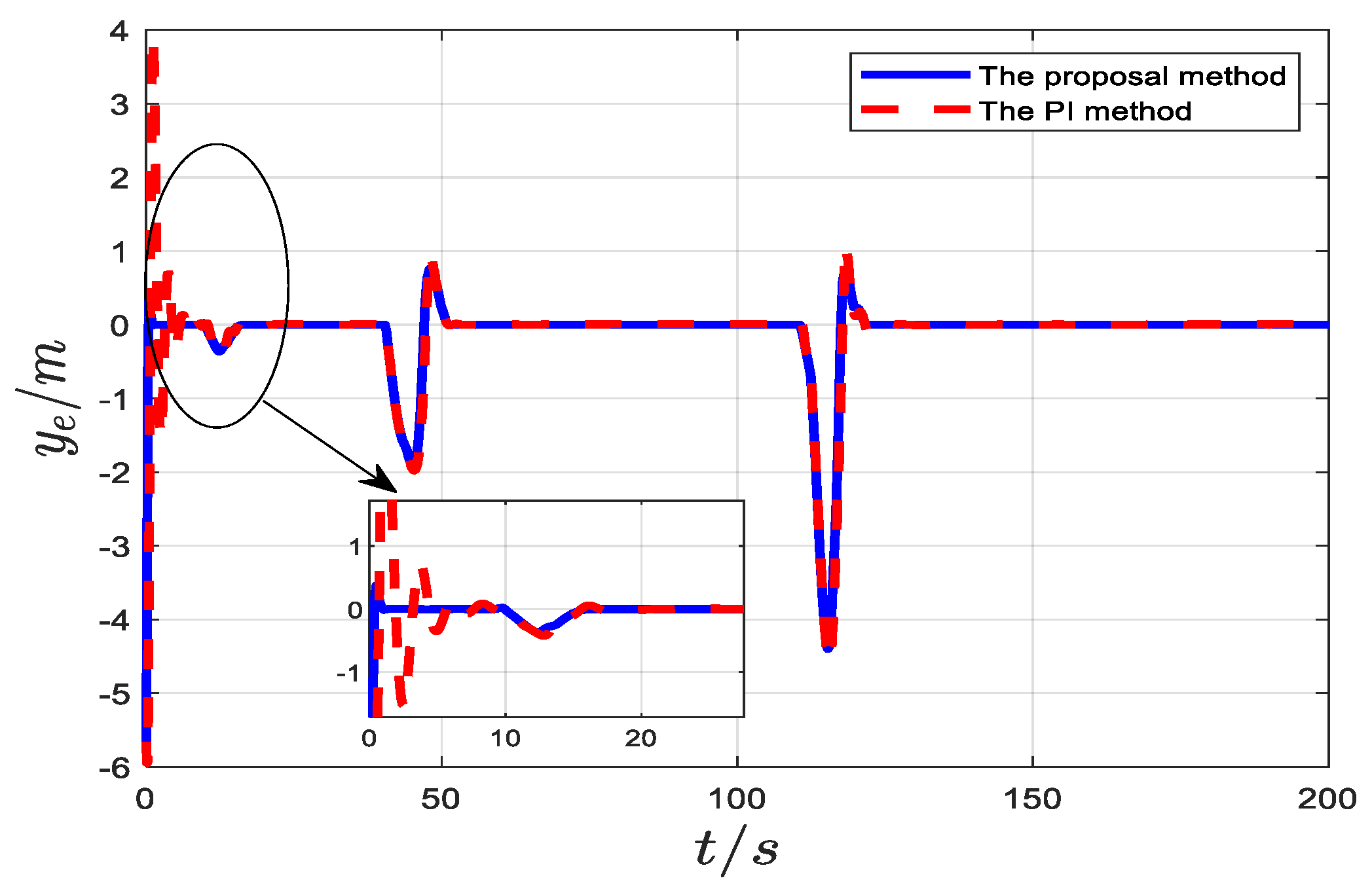
| The proposed controller | 2.0534 | 1.4330 | 0.1108 |
| The PI controller | 108.7973 | 10.4306 | 5.2420 |
| Comparative Control Methods | MSE | RMSE | MAE |
|---|---|---|---|
| The proposed controller | 0.1831 | 0.4279 | 0.0440 |
| The PI controller | 8.0354 | 2.8347 | 1.5029 |
Disclaimer/Publisher’s Note: The statements, opinions and data contained in all publications are solely those of the individual author(s) and contributor(s) and not of MDPI and/or the editor(s). MDPI and/or the editor(s) disclaim responsibility for any injury to people or property resulting from any ideas, methods, instructions or products referred to in the content. |
© 2024 by the authors. Licensee MDPI, Basel, Switzerland. This article is an open access article distributed under the terms and conditions of the Creative Commons Attribution (CC BY) license (https://creativecommons.org/licenses/by/4.0/).
Share and Cite
Wu, T.; Liu, Z.; Shi, G. Practical Fixed-Time Robust Containment Control of Multi-ASVs with Collision Avoidance. J. Mar. Sci. Eng. 2024, 12, 2363. https://doi.org/10.3390/jmse12122363
Wu T, Liu Z, Shi G. Practical Fixed-Time Robust Containment Control of Multi-ASVs with Collision Avoidance. Journal of Marine Science and Engineering. 2024; 12(12):2363. https://doi.org/10.3390/jmse12122363
Chicago/Turabian StyleWu, Tao, Zhengjiang Liu, and Guoyou Shi. 2024. "Practical Fixed-Time Robust Containment Control of Multi-ASVs with Collision Avoidance" Journal of Marine Science and Engineering 12, no. 12: 2363. https://doi.org/10.3390/jmse12122363
APA StyleWu, T., Liu, Z., & Shi, G. (2024). Practical Fixed-Time Robust Containment Control of Multi-ASVs with Collision Avoidance. Journal of Marine Science and Engineering, 12(12), 2363. https://doi.org/10.3390/jmse12122363