Article

Optimization-Based Energy Management Algorithm for 2-Stroke Hybrid Ship with Controllable Pitch Propeller

by
Nikolaos Aletras
1,
Apostolos Karvountzis-Kontakiotis
2,
Nikolaos Kefalas
1,
Achilleas Grigoriadis
1,
Zissis Samaras
1 and
Leonidas Ntziachristos
1,*
1
Laboratory of Applied Thermodynamics, Aristotle University of Thessaloniki, 54124 Thessaloniki, Greece
2
Winterthur Gas & Diesel Ltd., Schützenstrasse 1-3, 8401 Winterthur, Switzerland
*
Author to whom correspondence should be addressed.
J. Mar. Sci. Eng. 2024, 12(12), 2331; https://doi.org/10.3390/jmse12122331
Submission received: 8 November 2024 / Revised: 3 December 2024 / Accepted: 10 December 2024 / Published: 19 December 2024
(This article belongs to the Special Issue Advances in Recent Marine Engineering Technology)

Abstract

:
This paper examines the fuel consumption savings of a hybrid ship powertrain with 2-stroke main engine by implementing a novel adaptive equivalent consumption minimization strategy that utilizes a controllable pitch propeller. A non-hybrid powertrain model was developed as a demonstrator and real-world data were used for fuel consumption and efficiency maps. The baseline powertrain model was extended to a hybrid by introducing a shaft generator, a battery, a controllable pitch propeller, and the supervisory control algorithm. The potential benefits of the proposed powertrain are examined over different operation phases including port stay, open sea sailing, and port approach. The result showed that the energy efficiency gains can reach up to 6% under the open sea sailing phase. Furthermore, the controllable pitch propeller offers additional energy efficiency benefits of 2% under the port approach phase, utilizing the proposed algorithm. If the proposed powertrain is produced and the implemented algorithm is adopted, this could lead to substantial carbon dioxide emissions and fuel consumption savings at sea.

1. Introduction

Manmade carbon dioxide (CO2) emissions are recognized to be the main contributor to global warming [1] while, in turn, ships are major contributors to such CO2 emissions [2,3]. To address this problem, the International Maritime Organization (IMO) has introduced the carbon intensity indicator (CII), the energy efficiency design index (EEDI), and the energy efficiency existing ship index (EEXI), with the target to reduce the carbon intensity of the ship fleet above 5000 gross tonnage by 40% by 2030 compared to 2008 [4,5,6,7].
One technology option for meeting the IMO targets is to address CO2 emissions by the hybridization of the ship propulsion system [8]. Hybridization allows the main engine (ME) to operate at higher efficiency while part of the produced power is led to the batteries by means of a shaft generator (SG) [9]. CO2 benefits can be materialized by adapting the decisions of the energy management system (EMS) on the basis of energy optimization algorithms [10].
Optimization algorithms for hybrid ships are most commonly based on dynamic programming, model predictive control, and equivalent consumption minimization strategy (ECMS) techniques [11]. Dynamic programming (DP) offers a globally optimal solution but requires a priori knowledge of the power demand profile of the propulsion system and electrical consumers over a trip and incurs large computational times [12,13]. Model predictive control (MPC) can lead to solutions that are close to optimum but with lower computational cost than dynamic programming [14,15,16]. However, a prediction of the power demand profile for a period of 10 s to 600 s is required [14,15,16]. The ECMS reduces the computational cost by searching for instantaneous optimal solutions but might lead to solutions that deviate more from the global optimum one compared to DP and MPC [17,18,19]. However, the ECMS does not require prior or predicted knowledge of the power demand.
The ECMS has been implemented on hybrid ships equipped with either a 4-stroke [20,21] or 2-stroke [22] ME, with the latter offering higher thermal efficiency [22]. Two-stroke MEs with their high efficiency translate to more efficient generation of power for electrical consumers utilizing power take-off operation (PTO) with an SG, compared to power delivery from 4-stroke auxiliary engines [23]. Therefore, it is worth exploring how such a concept can be optimized to further decrease fuel oil consumption (FOC) in hybrid propulsion systems equipped with a 2-stroke ME.
Propulsion efficiency can be also improved by using a controllable pitch propeller (CPP) [24,25,26]. In maneuvering, the ME operates at a low load, leading to high specific FOC [24]. By using a CPP, such operation at low load is avoided [25] allowing the duration of the PTO to be extended by adjusting the rotational speed of the main shaft to the desired level [25,26]. Such an application was examined by Jaurola et al. [27,28] who investigated the performance of a hybrid ship with a 4-stroke ME using a CPP and applying the ECMS. There is no reference in the literature implementing such a concept to a ship with a 2-stroke ME, which is characterized by much higher thermal efficiency.
The current study exactly examines the potential FOC benefits offered by a novel adaptive ECMS on a ship equipped with a 2-stroke ME hybridized with an SG and a CPP. The benefits of the proposed powertrain and algorithm are analyzed for different operating conditions, including the phases of port stay, open sea sailing, and port approach. Adapting power systems on ships with the proposed hybrid system and adopting energy optimization algorithms could result in an immediate CO2 benefit for current ships and should also be considered for new builds.

2. Methodology

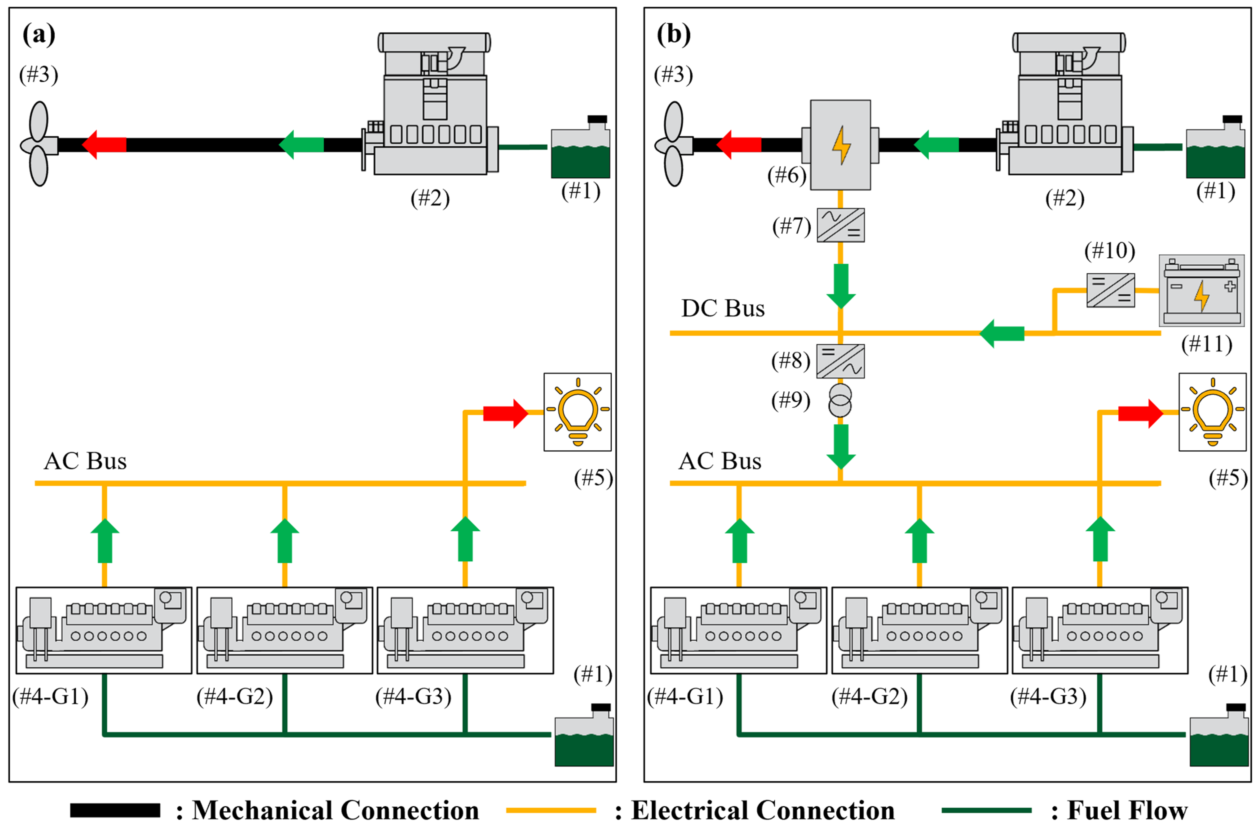
2.1. Examined Topologies

Two ship models were built in the MATLAB Simulink environment utilizing the library components in the powertrain blockset [29,30] to evaluate the hybrid engine room configuration (Figure 1b) against a conventional (non-hybrid) one (Figure 1a). The conventional configuration (Figure 1a) comprises two energy converters, namely, the ME and the gensets, both assumed to operate on the same fuel oil grade. The ME provides mechanical power to the propeller for ship propulsion, while the gensets produce electric power for onboard consumers. The hybrid configuration (Figure 1b) incorporates additional components over the conventional one, including an SG, electrical systems (transformer and inverters), and a battery pack. The SG and the electrical system form a bridge between the ME and the electrical consumers, allowing electrical power to flow to consumers also from the ME. Additionally, the battery pack optimizes load balancing and ensures an uninterrupted power supply [31].
The performance of the individual components and the propeller was modeled using efficiency and resistance data collected from actual sea trial tests conducted by Winterthur Gas & Diesel Ltd. [31,32]. The technical specifications of the main components are listed in Table 1 [33]. The CPP hybrid configuration can change its pitch position, while the FPP maintains a fixed pitch. In our case, two propeller positions are assumed for the CPP configuration. Adjusting the pitch position of the propeller alters its rotational speed and torque while maintaining constant power output [34]. In position 2, the propeller’s rotational speed increases by a factor of 1.8 compared to position 1, while its torque decreases by the same factor. CPP position 1 is chosen to be identical to the FPP in terms of rotational speed and torque to ensure a fair comparison between the two propeller types. CPP position 2 is selected by trial and error so as to minimize the brake-specific fuel oil consumption (BSFOC) of the ME under port approach conditions, where CPP utilization enables the ME to be overloaded with the PTO load.

2.2. Gensets Operation Rule for the Conventional Configuration

In the conventional configuration, the gensets are controlled by a simple rule as shown in Figure 2 [35]. The rule determines that one genset will handle the requested power from the electrical consumers until the genset load exceeds a threshold of 0.85 when the second genset is engaged, and the requested power is distributed among the two gensets. The same rule is followed while the power demand increases by enabling an increasing number of gensets (in the example of Figure 2, this max number is three). The 0.85 load threshold was selected to guarantee reliable operation and longevity of the gensets [35].

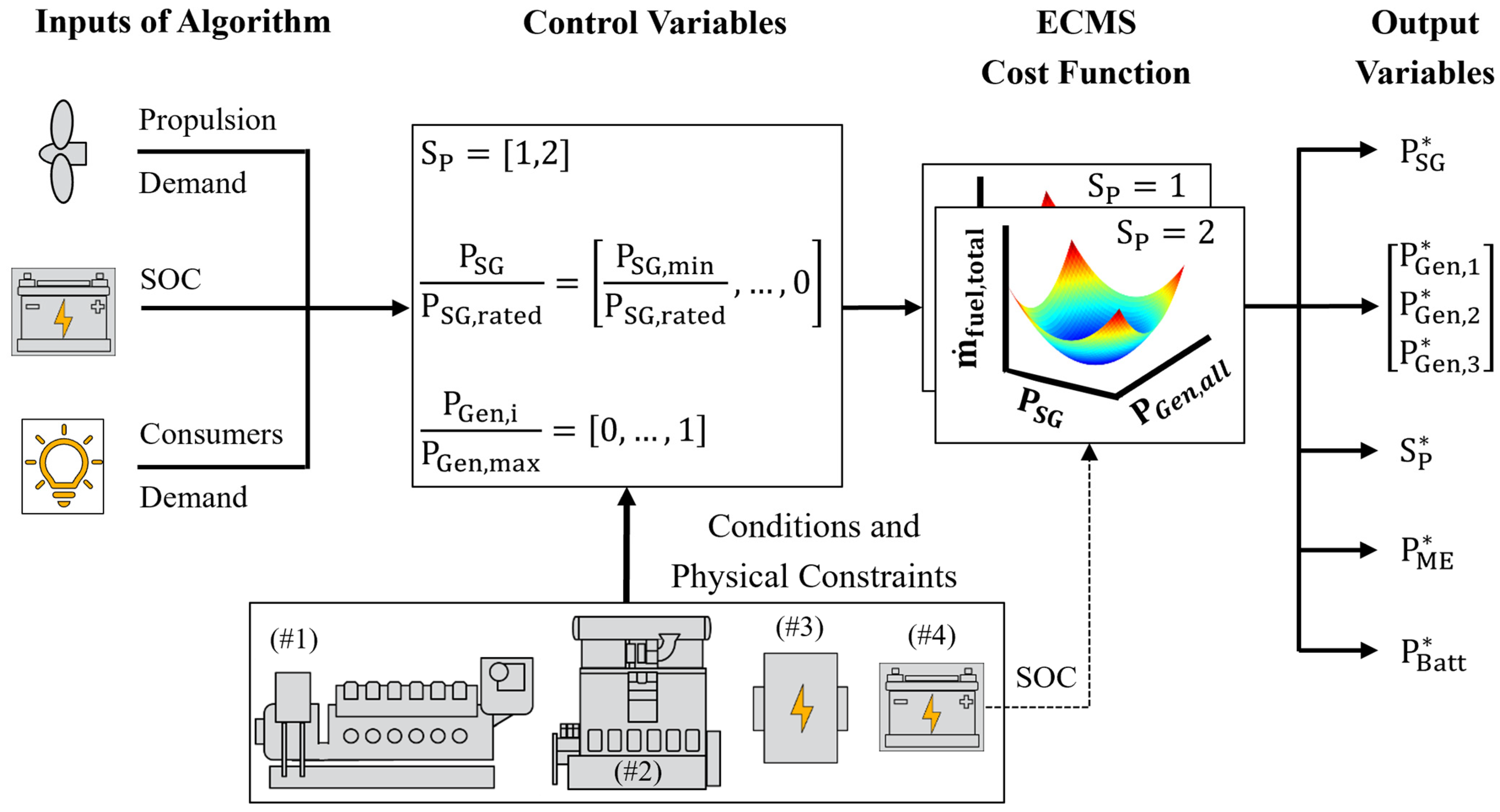
2.3. ECMS Implementation for the Hybrid Configuration

An ECMS algorithm was developed to optimize the operation of the proposed hybrid ship configuration. It was based on previous works [36,37] and was adapted and extended to include the cost factors of the main components in the engine room. Such an ECMS can be adapted and extended to consider the performance of major auxiliary consumers, as required in specific ships. The ECMS cost function ( m ˙ fuel , total ) is given by Equation (1), where m ˙ fuel , total must be minimized subject to the decision variables u 1 to u 5 (Equations (2)–(4)).
The ECMS cost function comprises three components for optimization. The first one is the fuel mass rate of the ME ( m ˙ fuel , ME ), which depends on the propeller position u 1 (Equation (2)), as changing the propeller position affects the rotational speed of the SG and ME shaft and the operating ME power. The latter depends on the normalized SG load function u 2 that ranges from 0 (PTO mode deactivated) to −1 (operation at minimum rated power, P SG ,   rated ), according to Equation (3), where P SG represents the SG power. The explored range of u 2 can be attributed to the fact that the implemented ECMS algorithm solely considers the SG to operate as a generator ( P SG 0) and not as a motor for the sake of simplicity.
The second component is the total fuel mass rate to the gensets ( m ˙ fuel , Gensets ), which depends on their normalized load functions u 3 , u 4 , and u 5 . These range from 0 (genset shut off) to 1 (operation at full power, P Gen , max ), according to Equation (4), where P Gen , 1 , P Gen , 2 , and P Gen , 3 represent the genset power for gensets 1 to 3.
The third component, P Batt , corresponds to the battery electric power that can either be positive or negative, depending on whether the battery is used to supply or absorb electrical energy, respectively. An additional cost factor ( p ) is added to P Batt to maintain the state of charge (SOC) around a target value. P Batt is converted to an equivalent fuel rate using the equivalence factor ( s eq ) and the lower heating value ( Q LHV ) of fuel oil. The p term is parametrized based on the equations presented by Onori et al. [38], with dependence on the SOC. The calculation schema for s eq and p can be found in the Appendix A with the selected parameters listed in Table A1, based on reasonable values found in Aletras et al. [37].
m ˙ fuel , total t = m ˙ fuel , ME + m ˙ fuel , Gensets + s eq Q LHV × P Batt × p SOC
u 1 = Propeller   Position   1 , Propeller   Position   2
u 2 =   P SG P SG , rated
u 3 u 4 u 5 = P Gen , 1 P Gen , max P Gen , 2 P Gen , max P Gen , 3 P Gen , max
The ECMS optimization is subject to the conditions of Equations (5)–(10). Equation (5) presents the mechanical power balance for the hybrid ship configuration. The demanded power at the propeller ( P Prop ) must be equal to the mechanical power output from the ME ( P ME ) and P SG . If the propeller rotational speed is known, then P Prop can be determined by the propeller curve. Equation (5) can therefore be used to determine P ME .
Equation (6) presents the electrical power balance for the hybrid ship configuration. The demanded power at electrical consumers ( P Consumers ) must be equal to the total electrical power output of the SG ( P SG ,   electric ), the gensets ( P Gen , all ), and P Batt . P SG ,   electric and the P Gen , all can be determined by using map-based modeling that considers the component efficiencies of the SG and gensets. So, if P Consumers is known, then P Batt can be determined by Equation (6).
Equations (7)–(10) correspond to the physical constraints of the components. Equation (7) implies that the ME cannot operate beyond full load, represented by the maximum ME power output ( P ME ,   max ). The SG is limited by its full load curve and the PTO power limitation with corresponding limits P SG , min and P PTO , limit according to Equation (8). The P PTO , limit function of rotation speed can be found in Figure A1 of the Appendix A. The gensets are limited to 0.85 of their full load curve according to Equation (9), where P Gen ,   i represents the genset power and i stands for genset numbering. Finally, the battery state of charge (SOC) cannot exceed a range of maximum ( SOC max ) and minimum ( SOC min ) levels for battery longevity (Equation (10)).
P Prop = P ME + P SG
P Consumers = P SG ,   electric + P Gen , all + P Batt  
P ME   P ME ,   max
P SG , min   P SG     0     P SG   P PTO , limit
P Gen ,   i   0.85 × P Gen , max   ,     i = 1 , 2 , 3
SOC min SOC SOC max
Figure 3 depicts the flowchart of the developed ECMS algorithm. The algorithm coordinates the operation of various components (ME, SG, gensets, battery, propeller) by seeking the solution that minimizes the cost function using P Prop , SOC and P Consumers as required input variables.
Initially, the algorithm establishes a range for the control variables based on the input data, the mechanical and electrical balance conditions, and the component physical constraints. Subsequently, the algorithm constructs the cost function matrix, considering the dependencies on the control variables. The algorithm then selects the combination of propeller position ( S P ), P SG , and gensets power values that leads to the minimum cost. The minimization procedure adheres to the methodology detailed in Aletras et al. [36]. Following the minimization process, Equations (5) and (6) are employed to determine the values of P ME and P Batt . The selected parameters for the ECMS algorithm can be found in Table A1 in the Appendix A.

2.4. Examined Operation Phases

In an initial step, the FOC benefits of the ECMS are benchmarked against the conventional configuration for various operation phases: port stay, open sea sailing, and port approach. To simulate these conditions, real-world trip profiles for propeller rotational speed and electrical consumer power demand of an anonymous deep sea ship operating under these conditions are utilized. The relevant profiles are illustrated in Figure A2 and Figure A3 of the Appendix A.
Table 2 summarizes the characteristics of the profiles employed for different operation phases. The duration of the activity is also normalized over the open sea sailing duration so as to use a common time frame across all scenarios. The average speed and average electrical consumers’ demand are also normalized over the ME rated speed and the rated power of one genset, respectively. Two distinct electrical consumer modes are examined for the port stay operation phase: one corresponding to electrical demand for cargo transfer onto the ship (“Cargo On”) and the other without this demand (“Cargo Off”). Two different electrical demand profiles are examined for the open sea sailing phase: one corresponding to when the ship’s ventilation system is switched on (“Ventilation On”) and the other when it is switched off (“Ventilation Off”). For the remaining phases, such as maneuvering or port approach, no specific electrical mode is activated (“Normal”).

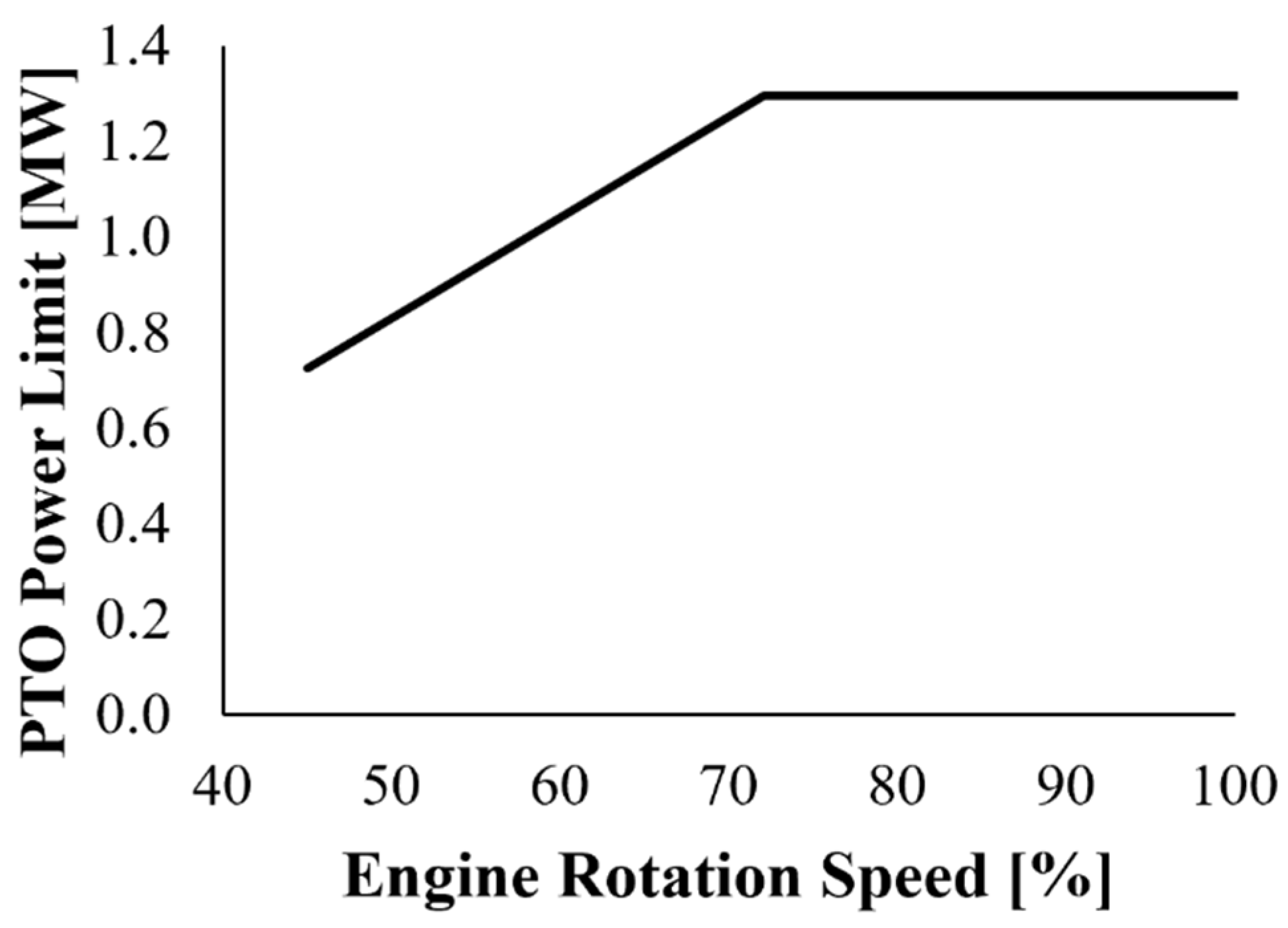
2.5. FOC Corrections

A fair assessment of any scenario considering hybrid or conventional engine rooms would necessitate that the energy for propulsion and electrical consumers is identical between scenarios. Moreover, in case a battery pack is utilized, any comparison should be conducted assuming equal SOC levels at the start and end of the simulation. However, this is not always the case. Modeling engine room configurations using dynamic simulators can lead to small differences in the propeller and electrical consumers’ power demand while maintaining SOC at the same level is not always respected [13,15,39]. These discrepancies could be avoided by employing a backward modeling simulator, which utilizes a quasi-static methodology. Nonetheless, in this study, a forward modeling simulator was selected owing to its foundation in physical causality, enabling the development of online control strategies [38].
To achieve a fair comparison, a correction method is therefore proposed, which adapts the method of Aletras et al. [37] to the examined ship engine room. This is achieved by normalizing the total simulated fuel consumption ( SE Fuel ) from the ME and gensets with the simulated energy demand at the propeller ( SE Prop ) and the electrical consumers ( SE Con ) in Equation (11). Comparing normalized FOC energy with total required energy enables a fair comparison between engine room configurations. This is because absolute FOC energy values can be misleading, as higher or lower energy demands from the propeller and other consumers can raise or lower the total FC energy needed. The relative FOC reductions (FOCRs) are obtained from the differences between the normalized corrected fuel energy consumption ( CE ^ Fuel ) values of the different configurations.
The new expression also uses the reference energy consumed from the battery ( RE Batt ) to set the simulated battery energy consumption ( SE Batt ) between the compared configurations to the same levels. Since the conventional configuration does not have a battery, RE Batt is set to zero. The efficiencies of the battery and the gensets received their average simulated values during the different phases ( η ¯ Batt and η ¯ Gensets , correspondingly).
CE ^ Fuel   =   SE Fuel SE Prop + SE Con + SE Batt RE Batt × 1 η ¯ Batt × 1 η ¯ Gensets SE Prop + SE Con | SE Batt RE Batt SE Fuel SE Prop +   SE Con + SE Batt RE Batt × η ¯ Batt × 1 η ¯ Gensets SE Prop + SE Con | SE Batt < RE Batt

3. Results

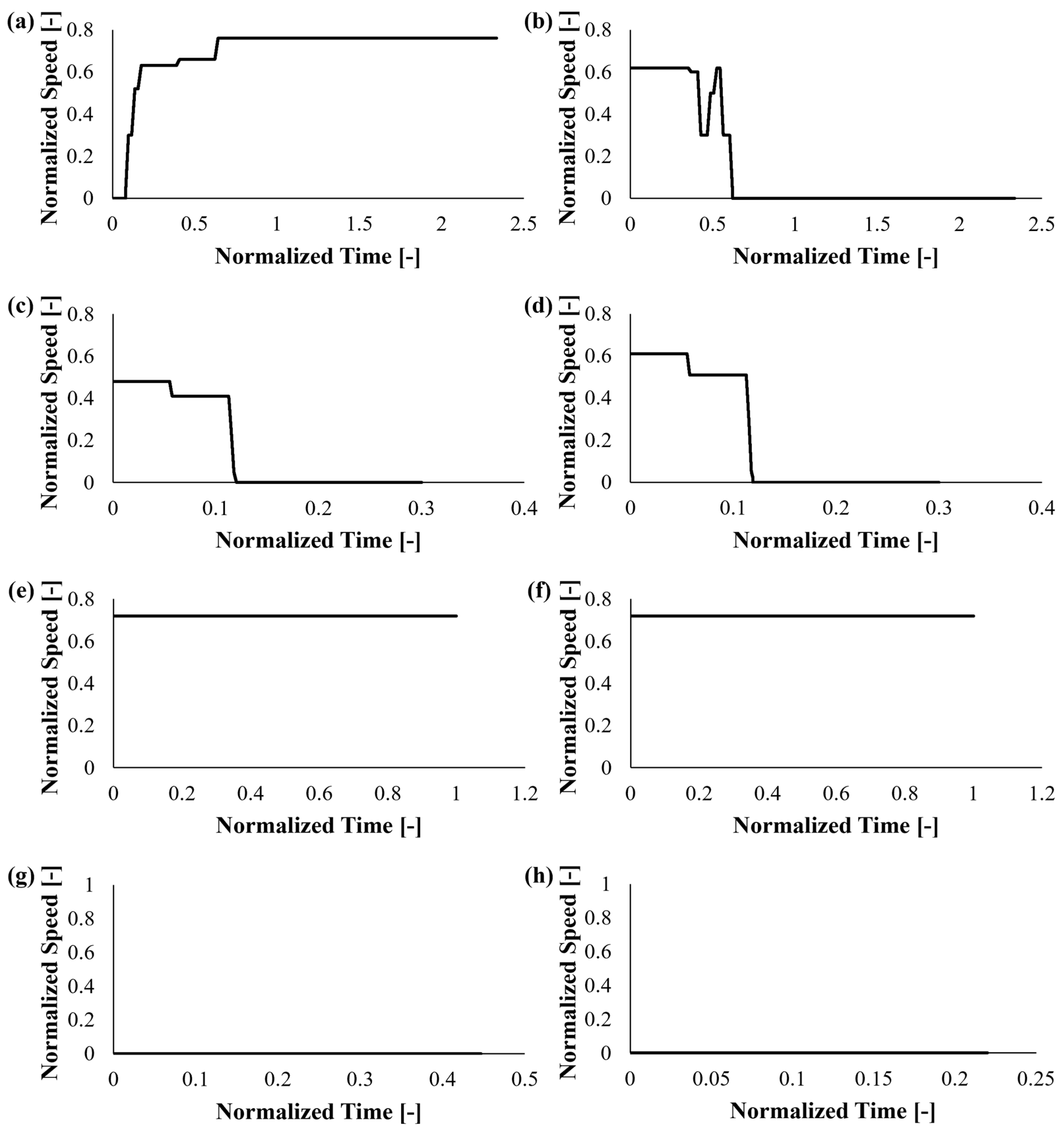
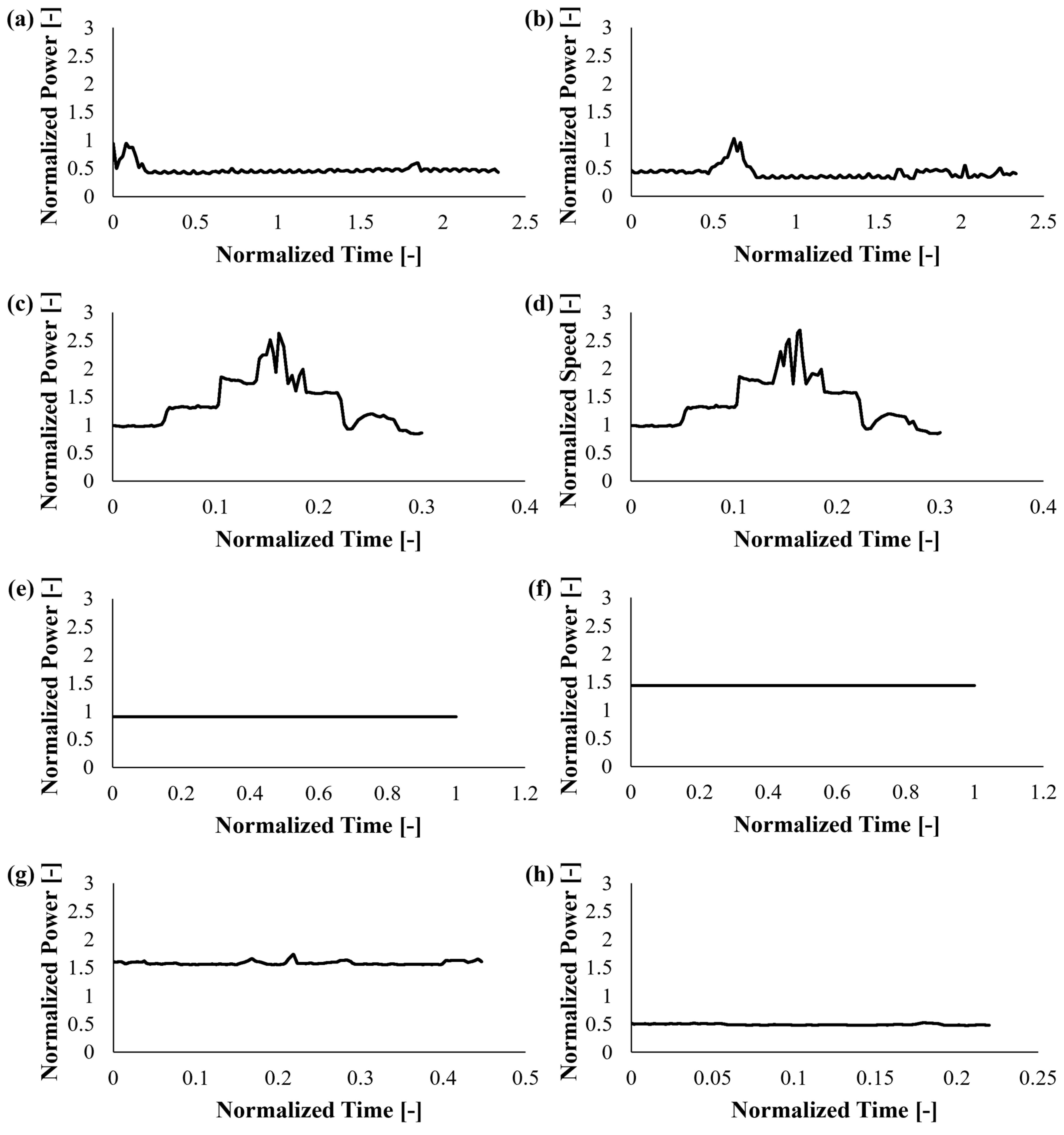
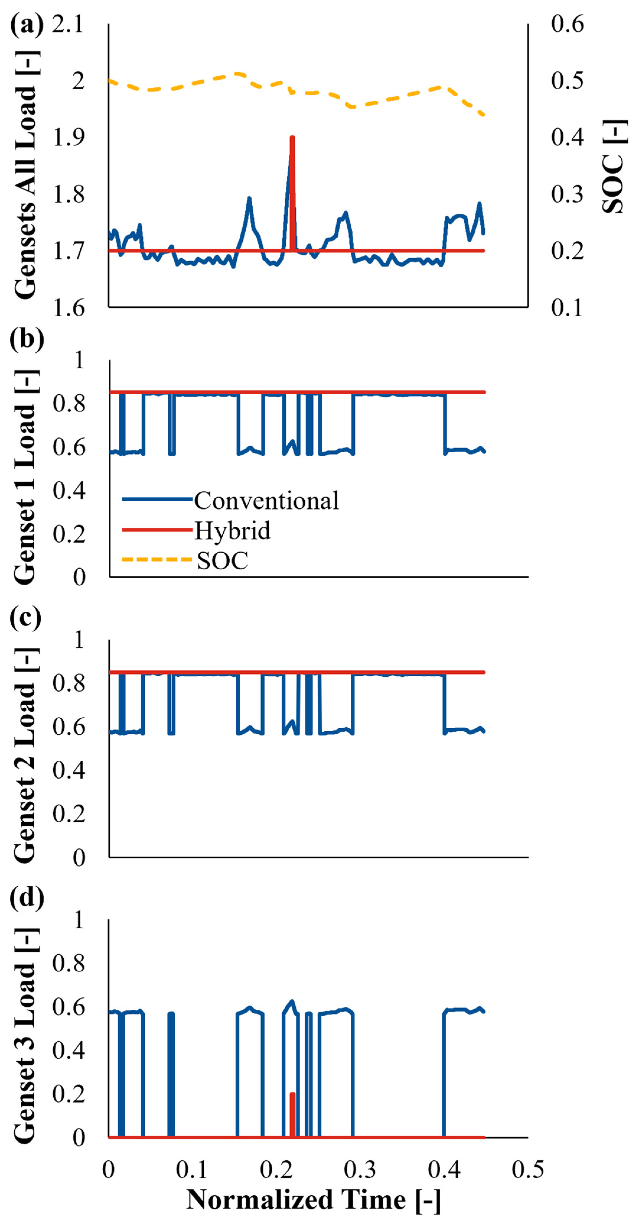
3.1. Port Stay Phase

Figure 4 presents genset load profiles during a port stay event where electricity is consumed to transfer cargo onto the ship (“Port Stay Cargo On”—Table 2). The ME is off so the gensets and the battery for the hybrid configuration cover the demand from the electrical consumers. In contrast, the conventional configuration solely relies on the gensets to fulfill this demand.
For the conventional configuration, the gensets load fluctuates in response to the varying electrical consumer power demand and it is distributed among all three gensets according to the rule depicted in Figure 2. In the hybrid configuration, the gensets load remains constant, with genset 1 and genset 2 operating at their maximum load capacity of 0.85. The battery acts as an energy buffer, addressing the power discrepancies between the electrical power supplied by the gensets and the required power from the electrical consumers, as illustrated by the SOC profile.
During the normalized time interval from 0.20 to 0.25, a brief surge occurs, requiring the engagement of the third genset. This is because the power demand of the electrical consumers increases, and the ECMS algorithm tries to maintain the battery at a steady level of 0.50.
The normalized net energy flows of the major components for the conventional and hybrid configurations are presented in Figure 5 for the “port stay cargo on” phase. The energy flows are normalized relative to the energy requirements of the electrical consumers. As the ship remains stationary, only the electrical parts of the configurations are depicted. In the conventional configuration, the energy demand of the electrical consumers is distributed among the three gensets, while in the hybrid configuration, it is primarily covered by gensets 1 and 2. The hybrid configuration employed with the ECMS algorithm results in a normalized FOC energy of 2.15, which is lower than that obtained from the conventional configuration of 2.22. This is attributed to the higher average genset efficiency in the case of the hybrid configuration, as the gensets operate at a higher load compared to the conventional configuration, as shown in Figure 4.
Table 3 summarizes the findings regarding the FOCR and average genset efficiency ( η ¯ Gensets ) both for the port stay cargo on and off phases. In addition to the port stay cargo on case, the phase where the ship does not use electrical consumers for cargo during port stay, designated as port stay cargo off, is also included. The hybrid configuration achieves a 3.15% FOCR during port stay cargo on and 0.81% during cargo off. The lower benefit during cargo off can be attributed to a less substantial improvement in genset efficiency. The net energy flow diagram for this case can be found in the Appendix A.

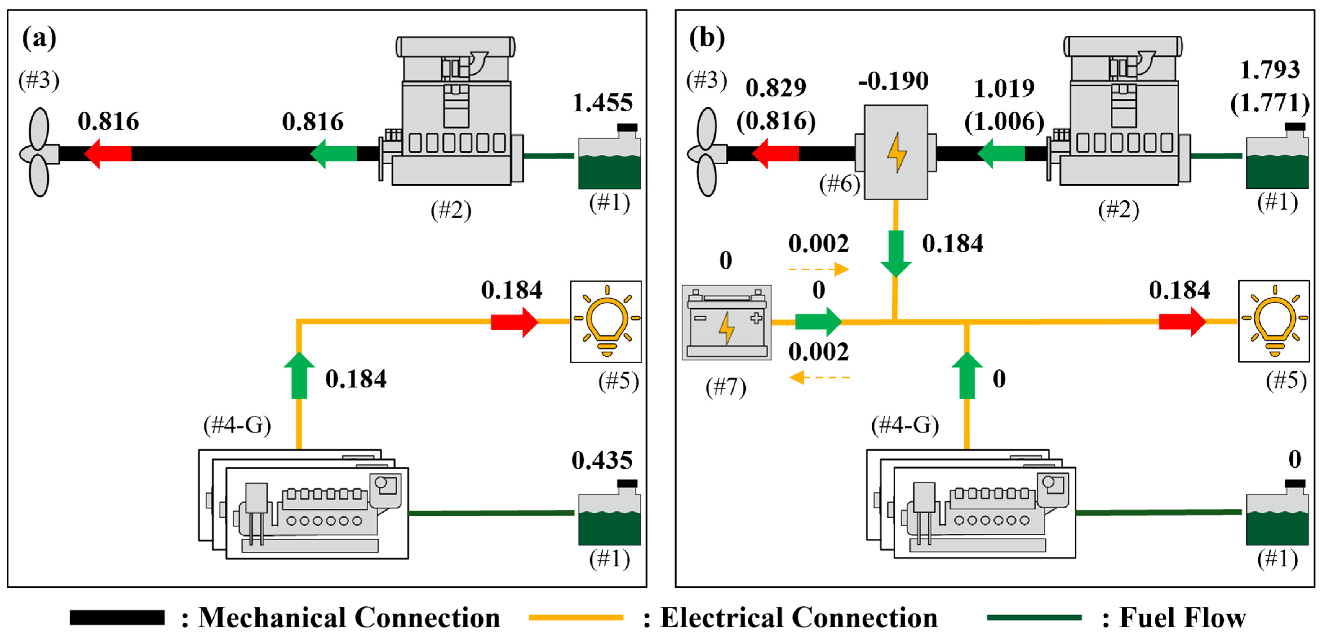
3.2. Open Sea Sailing Phase

Figure 6 depicts the operating points of the ME for open sea sailing when the ship’s ventilation system is switched off for both conventional and hybrid configurations. This condition will be referred to as “Open Sea Sailing Ventilation Off” (Table 2). In the conventional configuration, the ME load is governed by the propeller resistance curve to propel the ship and the gensets cover any electric loads. In hybrid mode, the ME operates at a higher load, supplying power both to the propeller and the SG for electricity generation. The latter fully covers electrical consumer demands, keeping the gensets inactive, as shown in Table 4.
Figure 7 illustrates the normalized net energy flows during open sea sailing ventilation off. The ME consumes more fuel oil in the hybrid configuration than in the conventional one due to the need to cover propulsion and electrical loads. However, the total normalized consumption, including the ME and gensets, is 1.79 in the hybrid configuration compared to 1.89 in the conventional. The main reason again is the higher efficiency of the 2-stroke ME at a high load compared to the 4-stroke gensets.
In the same figure, the results with FPP use are also given in parentheses, and consumption drops further compared to the CPP. Actually, the ECMS algorithm selects to operate the propeller at exactly the same pitch position for both cases. Therefore, the consumption discrepancy is mostly attributed to the higher efficiency of the FPP [40], leading to 0.816 normalized energy consumption compared to 0.829 for the CPP.
The results for the average efficiencies of ME ( η ¯ ME ), SG ( η ¯ SG ), and η ¯ Gensets , and the FOCR for open sea sailing are summarized in Table 5 in two scenarios for ventilation off and on. The hybrid configuration achieved 5.1% and 2.2% overall FOCR with ventilation off and on, respectively. In the hybrid configuration, PTO mode is enabled and the ME operates at a high load, thus increasing efficiency. Moreover, the ME with the SG results in more efficient electrical power generation than the gensets. However, as the SG is not enough to meet consumption when ventilation is on, the gensets are enabled and this results in somewhat lower FOC benefits of the hybrid system compared to the ventilation off case.

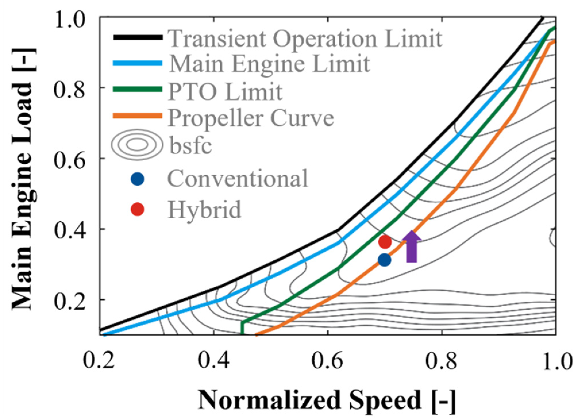
3.3. Port Entering and Leaving Modes

Figure 8 depicts the results for operation while the ship approaches the port at 6 kn. The figure compares the normalized shaft speed, loads for the SG, ME, and gensets, and SOC for the conventional and hybrid configurations with an FPP and a CPP. The shaft speed is normalized over the rated ME speed. The model satisfactorily follows the target rotational speed. For normalized time intervals from 0 to 0.06, the ECMS algorithm chooses to operate the SG at the same load and with the same propeller pitch for both the FPP and CPP. Accordingly, the ME operates at a higher load in the hybrid than in the conventional configuration to power both the propeller and the SG. Hence, the gensets provide less power in hybrid mode (Figure 8d) but are not completely off.
For the normalized time interval from 0.06 to 0.12, the rotational speed decreases, prompting the ECMS to deactivate PTO due to the physical constraints of the FPP hybrid configuration. Consequently, the SG is off, and the ME load drops to align with that in the conventional configuration. Since SG is off, the ECMS switches on the gensets to serve electrical consumption and maintain battery SOC within a desired range. In the CPP hybrid configuration within the same time frame, the ECMS adjusts the propeller at S P = 2 and increases its rotational speed, and this allows the SG to remain on while SG continues to serve electricity demands, at least in part. The additional degree of freedom offered by the CPP makes it possible to retain high-efficiency operation, which was not the case for the FPP.
Moving to the 0.12 to 0.30 interval, the ME shuts down in all configurations as the ship comes to a standstill. The electricity demand is solely met by the gensets in the conventional configuration and by the genset and batteries in the hybrid configuration.
The component efficiencies and FOCR during the 6 kn approach are summarized in Table 6. The higher ME load due to PTO results in higher efficiency in the hybrid configuration compared to the conventional one. Additionally, the hybrid configuration maintains gensets at higher loads also leading to higher efficiency compared to the conventional configuration. The CPP hybrid configuration even better utilizes PTO than the FPP hybrid bringing additional ME efficiency improvements. Similar to previous cases, a third reason for FOC improvement is the higher electricity production efficiency of the ME+SG than the gensets. For these reasons, the FOC benefits from the hybrid over the conventional configuration are 1.9% and 3.9% with the FPP and CPP, respectively.
For the remaining phases that include in-port or port approach phases, the CPP hybrid benefits range from 2.40% to 3.96% (Table 7), with additional benefits over the FPP depending on PTO mode time share ( t PTO ). As the ship starts maneuvering from open sea sailing, the CPP over FPP offers an additional 0.70 percentage units of FOC benefits, while this increases to 1.98 percentage units for the approach at the 6 kn approach phase. For the cases of the 12 kn approach and sailing from maneuvering, the efficiency gains with the CPP over FPP are negligible due to the modest increase in t PTO .

3.4. Parametric Analysis of Battery and SG Sizes on FOCR

Table 8 presents the impact of battery and SG sizes on FOCR achieved by the CPP hybrid configuration over the conventional one for different operation phases. Battery size variation within ±50% affects overall consumption by 0.2 up to 0.3 percentage units. The battery functions as an energy buffer between supplied power from the SG and gensets and consumer demands but does not serve as a sole power supplier. Hence, its size does not have a large impact on overall FOCR, as long as this is sufficient to maintain SOC within a desired range. On the other hand, reducing the SG rated power constrains electrical power generation by the ME forcing the gensets to operate more. Hence, decreasing SG size—e.g., to save costs—results in a drop in efficiency of up to 3.5 percentage units. Increasing SG size was not examined as the selected system is already near the P PTO , limit . As a result, it is verified that the initial component sizing of the SG and battery is adequate and no further modifications are necessary.

4. Discussion

This study explores how fuel oil consumption of a 2-stroke engine deep sea ship can be improved by using a shaft generator and batteries to create a hybrid propulsion system. To achieve this, a novel adaptive ECMS algorithm was developed based on real operation data, considering either a fixed (FPP) or a controllable pitch (CPP) propeller. Overall, hybrid propulsion with ECMS control led to efficiency gains of up to 6.0%, depending on the ship operating phase, with the greatest benefits observed in open sea sailing. The benefits are primarily attributed to higher ME efficiency, forcing this to operate at a higher load in the PTO hybrid operation and more efficient electricity generation by the SG than the gensets in the conventional configuration. The latter is because of 4-stroke combustion in the gensets compared to the higher thermal efficiency of the ME’s 2-stroke combustion. The consumption benefits are more marginal at port stay phases as the PTO cannot be enabled.
The range of consumption improvements achieved needs to be compared to the 11% improvement reported by Kim et al. [41] and the 1.6–18.9% savings reported by Diniz et al. [42]. In both studies, the ECMS was employed for hybrid control, and the benefits over conventional operation were shown for fishing boats (Kim et al. [41]) and shuttle tankers and tugboats (Diniz et al. [42]). However, those studies did not address deep sea ships like in the current study. Published results with other types of EMS algorithms include the study of Al-Falahi et al. [43], who demonstrated a rule-based algorithm offering 2.9% benefits of a hybrid operation and a gray-wolf strategy increasing this to 7.5%, and Planakis et al. [44] who proposed a nonlinear MPC for hybrid control resulting in a benefit of 2%. In addition, Kim et al. [45] presented a study for the optimal load-sharing algorithm between an SG and gensets for hybrid ships, offering benefits in the range of 5.5 to 7.2%.
A CPP increases benefits over an FPP by up to two percentage units, especially in operation phases that include port approach and maneuvering operations. This is comparable to the improvement of 1.7 to 7.6 percentage units reported by Jaurola et al. [28] and 4.9 percentage units reported by Tian et al. [46] with a CPP over an FPP. A CPP allows PTO mode to be enabled more frequently than an FPP, thereby amplifying the benefits of the hybrid configuration. Obviously, in port stay and open sea sailing phases, a CPP does not offer benefits as the propeller is off or already optimized in FPP mode, respectively.
Although efficiency gains appear small, these are still significant if one considers that retrofitting an SG and a battery pack is among the simplest interventions a ship can go through in its pursuit of meeting CII and EEXI indicators. They are also readily available for new builds. A CPP offers additional benefits and one will have to trade off with the cost of investment. In any case, an enhanced ECMS control algorithm can maximize efficiency benefits, and the significant effort of moving away from rule-based approaches is recommended. In a commercial implementation of such an EMS, one can and should include additional functionalities for auxiliary use and any emission control devices of the ship, such as scrubbers and SCRs. Evidently, the exact benefits will depend on the ship type and operation but these can be readily calculated once real-world operational profiles are made available. A big advantage of an ECMS is its adaptability to specific uses, without loss of generality, as opposed to rule-based approaches that need to be fine-tuned for each individual application. Commercializing such technologies and extending hybrid powertrains to other ship classes could pave the way toward decarbonizing the marine sector.

5. Conclusions

This paper examines the fuel consumption benefits offered by a novel adaptive ECMS to a ship equipped with a 2-stroke ME hybridized with an SG and a CPP. The main outcomes of the current study can be summarized as follows:
  • The hybridization of the engine room leads to benefits of up to 6% compared to a conventional configuration, depending on operating conditions.
  • The benefits are maximized during open sea sailing, where PTO is enabled more frequently, leading to more efficient electricity generation by the SG compared to gensets in the conventional configuration.
  • Integrating CPP usage into the ECMS algorithm can increase FC benefits by up to 2.0 percentage points compared to an FPP hybrid configuration, particularly during port approach and maneuvering operations. The reason is that a CPP allows PTO mode to be enabled more frequently than an FPP.
By incorporating the proposed hybrid system and energy management algorithm into ship power systems, significant reductions in CO2 emissions can be achieved for existing ships. This approach should also be considered for new ship designs. This technological innovation offers a potential solution for reducing the carbon footprint of the maritime industry.

Author Contributions

Conceptualization, N.A., A.K.-K. and L.N.; methodology, N.A., A.K.-K. and L.N.; software, N.A., N.K. and A.K.-K.; validation, N.A., N.K. and A.K.-K.; formal analysis, N.A. and N.K.; investigation, N.A. and A.K.-K.; resources, L.N. and Z.S.; data curation, N.A. and N.K.; writing—original draft preparation, N.A.; writing—review and editing, N.A., A.K.-K., A.G. and L.N.; visualization, N.A. and N.K.; supervision, L.N. and Z.S.; project administration, L.N. All authors have read and agreed to the published version of the manuscript.

Funding

This research work was supported by the Hellenic Foundation for Research and Innovation (HFRI) under the 3rd Call for HFRI PhD Fellowships (Fellowship Number: 6653).

Institutional Review Board Statement

Not applicable.

Informed Consent Statement

Not applicable.

Data Availability Statement

The data will be made available upon request.

Acknowledgments

The authors would like to acknowledge the support of this work by the personnel of the WinGD team for providing the data of the powertrain. This research work was supported by the Hellenic Foundation for Research and Innovation (HFRI) under the 3rd Call for HFRI PhD Fellowships (Fellowship Number: 6653).

Conflicts of Interest

Author Dr. Apostolos Karvountzis-Kontakiotis was employed by the company Winterthur Gas & Diesel Ltd. The remaining authors declare that the research was conducted in the absence of any commercial or financial relationships that could be construed as a potential conflict of interest.

Abbreviations

BSFOCbrake-specific fuel oil consumption
CIIcarbon intensity indicator
CO2carbon dioxide
CPPcontrollable pitch propeller
DPdynamic programming
ECMSequivalent minimization consumption strategy
EEDIenergy efficiency design index
EEXIenergy efficiency existing ship index
EMSenergy management system
FOCfuel oil consumption
FOCRFOC reduction
FPPfixed pitch propeller
IMOinternational maritime organization
MEmain engine
MPCmodel predictive control
SGshaft generator
Sppropeller position
tPTOPTO mode activation time share
η ¯ ME average ME efficiency
η ¯ Gensets average gensets efficiency
η ¯ SG average SG efficiency

Appendix A

The equivalence factor is given by Equation (A1) while the p factor is given by Equation (A2).
s eq = s dis | P Batt 0 s c h g | P Batt < 0  
p SOC = 1 SOC t SOC target SOC max SOC min × 0.5 a
Table A1. ECMS algorithm parameters.
ParameterValue
s dis 3.6
s c h g 1.1
a1
SOC target 0.5
SOC m a x 0.8
SOC m i n 0.2
Figure A1. PTO power limit for the SG operating power.
Jmse 12 02331 g0a1
Figure A2. Propeller rotational speed for (a) from port maneuvering to sailing, (b) from sailing to port maneuvering, (c) 6 kn approach, (d) 12 kn approach, (e) open sea sailing ventilation off, (f) open sea sailing ventilation on, (g) port stay cargo on, and (h) port stay cargo off.
Jmse 12 02331 g0a2
Figure A3. Electrical consumer power demand profiles for (a) from port maneuvering to sailing, (b) from sailing to port maneuvering, (c) 6 kn approach, (d) 12 kn approach, (e) open sea sailing ventilation off, (f) open sea sailing ventilation on, (g) port stay cargo on, and (h) port stay cargo off.
Jmse 12 02331 g0a3
Figure A4. Energy flows for the conventional (a) and hybrid (b) configurations, where (#1): fuel tank, (#2): main engine, (#3): propeller, (#4-G1): genset 1, (#4-G2): genset 2, (#4-G3): genset 3, (#5): auxiliary loads, (#6): shaft generator, and (#7): battery pack.
Jmse 12 02331 g0a4
Table A2. Energy flows for the conventional configuration.
PointOperation Phase
Port Stay Cargo OnPort Stay Cargo OffOpen Sea Sailing
Ventilation On
Open Sea Sailing
Ventilation Off
6 kn
Approach
12 kn
Approach
From Port Maneuvering to
Sailing
From Sailing to Port
Maneuvering
A0.0000.0001.3131.4550.4900.6941.5861.071
B0.0000.0000.7360.8160.2100.3470.8950.558
C0.0000.0000.7360.8160.2100.3470.8950.558
D2.2222.3320.5740.4351.7801.4720.2481.086
E0.9552.3320.2870.21750.7670.6340.2411.047
F0.9550.0000.2870.21750.7670.6340.0070.039
G0.3110.0000.0000.0000.2460.2040.0000.000
H0.4341.0000.1320.0920.3400.2810.1020.424
I0.4340.0000.1320.0920.3400.2810.0030.018
J0.1320.0000.0000.0000.1100.0910.0000.000
K1.0001.0000.2640.1840.7900.6530.1050.442
L1.0001.0000.2640.1840.7900.6530.1050.442
M0.0000.0000.0000.0000.0000.0000.0000.000
N0.0000.0000.0000.0000.0000.0000.0000.000
O0.0000.0000.0000.0000.0000.0000.0000.000
P0.0000.0000.0000.0000.0000.0000.0000.000
Q0.0000.0000.0000.0000.0000.0000.0000.000
R0.0000.0000.0000.0000.0000.0000.0000.000
Table A3. Energy flows for the hybrid configuration without a CPP.
PointOperation Phase
Port Stay Cargo OnPort Stay Cargo OffOpen Sea Sailing
Ventilation On
Open Sea Sailing
Ventilation Off
6 kn
Approach
12 kn
Approach
From Port Maneuvering to
Sailing
From Sailing to Port
Maneuvering
A0.0000.0001.5291.7710.5380.8771.7471.236
B0.0000.0000.8651.0060.2360.4630.9940.666
C0.0000.0000.7360.8160.2100.3470.8950.558
D2.1522.3130.2980.0001.6881.2010.0190.859
E1.0762.3130.2980.0000.9670.7110.0190.855
F1.0760.0000.0000.0000.5880.3870.0000.004
G0.0000.0000.0000.0000.1330.1030.0000.000
H0.5001.0000.1390.0000.4390.3210.0090.336
I0.5000.0000.0000.0000.2670.1740.0000.002
J0.0000.0000.0000.0000.0600.0470.0000.000
K1.0001.0000.1390.0000.7660.5420.0090.338
L1.0001.0000.2640.1840.7900.6530.1050.442
M0.0000.000−0.129−0.190−0.026−0.116−0.099−0.108
N0.0000.0000.1250.1840.0240.1110.0960.104
O0.0000.0000.0000.0000.0000.0000.0000.000
P0.0090.1100.0130.0020.0160.0120.0020.021
Q0.0090.1100.0130.0020.0160.0120.0020.021
R0.0000.0000.0000.0000.0000.0000.0000.000
Table A4. Energy flows for the hybrid configuration with a CPP.
PointOperation Phase
Port Stay Cargo OnPort Stay Cargo OffOpen Sea Sailing
Ventilation On
Open Sea Sailing
Ventilation Off
6 kn
Approach
12 kn
Approach
From Port Maneuvering to
Sailing
From Sailing to Port
Maneuvering
A0.0000.0001.5491.7930.7570.8871.7711.318
B0.0000.0000.8771.0190.3550.4671.0080.711
C0.0000.0000.7480.8290.2120.3510.9090.571
D2.1522.3130.2980.0001.4241.2010.0190.762
E1.0762.3130.2980.0000.8900.7110.0190.760
F1.0760.0000.0000.0000.4300.3870.0000.002
G0.0000.0000.0000.0000.1040.1030.0000.000
H0.5001.0000.1390.0000.4080.3210.0090.306
I0.5000.0000.0000.0000.1970.1740.0000.001
J0.0000.0000.0000.0000.0480.0470.0000.000
K1.0001.0000.1390.0000.6530.5420.0090.307
L1.0001.0000.2640.1840.7900.6530.1050.442
M0.0000.000−0.129−0.190−0.143−0.116−0.099−0.140
N0.0000.0000.1250.1840.1370.1110.0960.135
O0.0000.0000.0000.0000.0000.0000.0000.000
P0.0090.1100.0130.0020.0230.0120.0020.030
Q0.0090.1100.0130.0020.0230.0120.0020.030
R0.0000.0000.0000.0000.0000.0000.0000.000
Table A5. SG sizing impact on FOC reduction.
SG Sizing FOCR Nominal FOCR Variation
Port Stay Cargo OnPort Stay Cargo OffOpen Sea Sailing
Ventilation On
Open Sea Sailing
Ventilation Off
6 kn
Approach
12 kn
Approach
From Port Maneuvering to
Sailing
From Sailing to Port
Maneuvering
90%0.00.00.1−0.40.30.500.4
80%0.00.00.10.70.40.500.4
70%0.00.00.13.50.90.800.3
60%0.00.00.43.50.91.200.4
50%0.00.02.23.51.41.60.10.4

References

  1. Hansen, J.E.; Sato, M.; Simons, L.; Nazarenko, L.S.; Sangha, I.; Kharecha, P.; Zachos, J.C.; von Schuckmann, K.; Loeb, N.G.; Osman, M.B.; et al. Global warming in the pipeline. Oxf. Open Clim. Chang. 2023, 3, kgad008. [Google Scholar] [CrossRef]
  2. IEA. CO2 Emissions in 2022. Available online: https://www.iea.org/reports/co2-emissions-in-2022 (accessed on 9 December 2024).
  3. Cars, Planes, Trains: Where Do CO2 Emissions from Transport Come From? Available online: https://ourworldindata.org/co2-emissions-from-transport (accessed on 9 December 2024).
  4. IMO. 2023 IMO Strategy on Reduction of GHG Emissions from Ships. Available online: https://www.imo.org/en/OurWork/Environment/Pages/2023-IMO-Strategy-on-Reduction-of-GHG-Emissions-from-Ships.aspx (accessed on 9 December 2024).
  5. IMO. IMO’s Work to Cut GHG Emissions from Ships. Available online: https://www.imo.org/en/MediaCentre/HotTopics/Pages/Cutting-GHG-emissions.aspx (accessed on 9 December 2024).
  6. DNV. CII—Carbon Intensity Indicator. Available online: https://www.dnv.com/maritime/insights/topics/CII-carbon-intensity-indicator/answers-to-frequent-questions.html (accessed on 9 December 2024).
  7. IMO. Improving the Energy Efficiency of Ships. Available online: https://www.imo.org/en/OurWork/Environment/Pages/Improving%20the%20energy%20efficiency%20of%20ships.aspx (accessed on 9 December 2024).
  8. Inal, O.B.; Charpentier, J.-F.; Deniz, C. Hybrid Power and Propulsion Systems for Ships: Current Status and Future Challenges. Renew. Sustain. Energy Rev. 2022, 156, 111965. [Google Scholar] [CrossRef]
  9. Geertsma, R.D.; Negenborn, R.R.; Visser, K.; Hopman, J.J. Design and control of hybrid power and propulsion systems for smart ships: A review of developments. Appl. Energy 2017, 194, 30–54. [Google Scholar] [CrossRef]
  10. Fan, A.; Li, Y.; Liu, H.; Yang, L.; Tian, Z.; Li, Y.; Vladimir, N. Development trend and hotspot analysis of ship energy management. J. Clean. Prod. 2023, 389, 135899. [Google Scholar] [CrossRef]
  11. Roslan, S.B.; Konovessis, D.; Tay, Z.Y. Sustainable Hybrid Marine Power Systems for Power Management Optimisation: A Review. Energies 2022, 15, 9622. [Google Scholar] [CrossRef]
  12. Zhang, Y.; Xue, Q.; Gao, D.; Shi, W.; Yu, W. Two-level model predictive control energy management strategy for hybrid power ships with hybrid energy storage system. J. Energy Storage 2022, 52, 104763. [Google Scholar] [CrossRef]
  13. Planakis, N.; Papalambrou, G.; Kyrtatos, N. Ship energy management system development and experimental evaluation utilizing marine loading cycles based on machine learning techniques. Appl. Energy 2022, 307, 118085. [Google Scholar] [CrossRef]
  14. Antonopoulos, S.; Visser, K.; Kalikatzarakis, M.; Reppa, V. MPC Framework for the Energy Management of Hybrid Ships with an Energy Storage System. J. Mar. Sci. Eng. 2021, 9, 993. [Google Scholar] [CrossRef]
  15. Yuan, L.C.W.; Tjahjowidodo, T.; Lee, G.S.G.; Chan, R. Optimizing fuel savings and power system reliability for all-electric hybrid vessels using Model Predictive Control. In Proceedings of the 2017 IEEE International Conference on Advanced Intelligent Mechatronics (AIM), Munich, Germany, 3–7 July 2017; IEEE: Piscataway, NJ, USA, 2017; pp. 1532–1537, ISBN 978-1-5090-5998-0. [Google Scholar] [CrossRef]
  16. Xie, P.; Guerrero, J.M.; Tan, S.; Bazmohammadi, N.; Vasquez, J.C.; Mehrzadi, M.; Al-Turki, Y. Optimization-Based Power and Energy Management System in Shipboard Microgrid: A Review. IEEE Syst. J. 2022, 16, 578–590. [Google Scholar] [CrossRef]
  17. Chua, L.W.Y.; Tjahjowidodo, T.; Seet, G.G.L.; Chan, R. Implementation of Optimization-Based Power Management for All-Electric Hybrid Vessels. IEEE Access 2018, 6, 74339–74354. [Google Scholar] [CrossRef]
  18. Yuan, L.C.W.; Tjahjowidodo, T.; Lee, G.S.G.; Chan, R.; Ådnanes, A.K. Equivalent consumption minimization strategy for hybrid all-electric tugboats to optimize fuel savings. In Proceedings of the 2016 American Control Conference (ACC), Boston, MA, USA, 6–8 July 2016; IEEE: Piscataway, NJ, USA, 2017; pp. 6803–6808, ISBN 978-1-4673-8682-1. [Google Scholar] [CrossRef]
  19. Zhu, J.; Chen, L.; Wang, X.; Yu, L. Bi-level optimal sizing and energy management of hybrid electric propulsion systems. Appl. Energy 2020, 260, 114134. [Google Scholar] [CrossRef]
  20. Kalikatzarakis, M.; Geertsma, R.D.; Boonen, E.J.; Visser, K.; Negenborn, R.R. Ship energy management for hybrid propulsion and power supply with shore charging. Control. Eng. Pr. 2018, 76, 133–154. [Google Scholar] [CrossRef]
  21. Chua, L.W.Y. A Strategy for Power Management of Electric Hybrid Marine Power Systems; Nanyang Technological University: Singapore, 2019. [Google Scholar] [CrossRef]
  22. Dedes, E.K.; Hudson, D.A.; Turnock, S.R. Investigation of Diesel Hybrid systems for fuel oil reduction in slow speed ocean going ships. Energy 2016, 114, 444–456. [Google Scholar] [CrossRef]
  23. Sui, C.; Stapersma, D.; Visser, K.; de Vos, P.; Ding, Y. Energy effectiveness of ocean-going cargo ship under various operating conditions. Ocean Eng. 2019, 190, 106473. [Google Scholar] [CrossRef]
  24. Nguyen, H.P.; Hoang, A.T.; Nizetic, S.; Nguyen, X.P.; Le, A.T.; Luong, C.N.; Chu, V.D.; Pham, V.V. The electric propulsion system as a green solution for management strategy of CO2 emission in ocean shipping: A comprehensive review. Int. Trans. Electr. Energy Syst. 2021, 31, e12580. [Google Scholar] [CrossRef]
  25. Bacciaglia, A.; Ceruti, A.; Liverani, A. Controllable pitch propeller optimization through meta-heuristic algorithm. Eng. Comput. 2021, 37, 2257–2271. [Google Scholar] [CrossRef]
  26. Wärtsilä. Controllable Pitch Propeller Systems. Available online: https://www.wartsila.com/marine/products/propulsors-and-gears/propellers/wartsila-controllable-pitch-propeller-systems (accessed on 9 December 2024).
  27. Jaurola, M.; Hedin, A.; Tikkanen, S.; Huhtala, K. TOpti: A flexible framework for optimising energy management for various ship machinery topologies. J. Mar. Sci. Technol. 2019, 24, 1183–1196. [Google Scholar] [CrossRef]
  28. Jaurola, M.; Hedin, A.; Tikkanen, S.; Huhtala, K. A TOpti simulation for finding fuel saving by optimising propulsion control and power management. J. Mar. Sci. Technol. 2020, 25, 411–425. [Google Scholar] [CrossRef]
  29. MathWorks. Simulink. Available online: https://www.mathworks.com/products/simulink.html (accessed on 9 December 2024).
  30. MathWorks. Powertrain Blockset. Available online: https://www.mathworks.com/products/powertrain.html (accessed on 9 December 2024).
  31. WinGD. X-EL–Energy Management. Available online: https://www.wingd.com/en/technology-innovation/hybrid-energy-systems/ (accessed on 9 December 2024).
  32. WinGD. X62DF-2.1. Available online: https://www.wingd.com/en/engines/engine-types/x-df-dual-fuel/x62df-2-1/ (accessed on 9 December 2024).
  33. Leclanché. Available online: https://www.leclanche.com/ (accessed on 9 December 2024).
  34. Altosole, M.; Borlenghi, M.; Capasso, M.; Figari, M. Computer-based design tool for a fuel efficient-low emissions marine propulsion plant. In Proceedings of the 2nd International Conference on Marine Research and Transportation, ICMRT’07, Ischia, Napels, Italy, 28–30 June 2007. [Google Scholar]
  35. HD Hyundai Heavy Industries. Hi-Touch Marine & Stationary ENgine. Available online: https://www.hyundai-engine.com/en/aboutus/Himsen (accessed on 9 December 2024).
  36. Aletras, N.; Doulgeris, S.; Samaras, Z.; Ntziachristos, L. Comparative Assessment of Supervisory Control Algorithms for a Plug-In Hybrid Electric Vehicle. Energies 2023, 16, 1497. [Google Scholar] [CrossRef]
  37. Aletras, N.; Broekaert, S.; Bitsanis, E.; Fontaras, G.; Samaras, Z.; Ntziachristos, L. Energy management algorithm based on average power demand prediction for plug-in hybrid electric trucks. Energy Convers. Manag. 2024, 299, 117785. [Google Scholar] [CrossRef]
  38. Onori, S.; Serrao, L.; Rizzoni, G. Hybrid Electric Vehicles; Springer: London, UK, 2016; ISBN 978-1-4471-6779-2. [Google Scholar] [CrossRef]
  39. Chan, R.R.; Chua, L.; Tjahjowidodo, T. Enabling technologies for sustainable all—Electric hybrid vessels (Invited paper). In Proceedings of the 2016 IEEE International Conference on Sustainable Energy Technologies (ICSET), Hanoi, Vietnam, 4–16 November 2016; IEEE: Piscataway, NJ, USA, 2016; pp. 401–406, ISBN 978-1-5090-5200-4. [Google Scholar] [CrossRef]
  40. MAN. Basic Principles of Ship Propulsion. Available online: https://www.man-es.com/docs/default-source/document-sync-archive/basic-principles-of-ship-propulsion-eng.pdf?sfvrsn=48fc05b5_7 (accessed on 9 December 2024).
  41. Kim, S.; Jeon, H.; Park, C.; Kim, J. Lifecycle Environmental Benefits with a Hybrid Electric Propulsion System Using a Control Algorithm for Fishing Boats in Korea. J. Mar. Sci. Eng. 2022, 10, 1202. [Google Scholar] [CrossRef]
  42. Diniz, G.H.S.; dos Santos Miranda, V.; Carmo, B.S. Dynamic modelling, simulation, and control of hybrid power systems for escort tugs and shuttle tankers. J. Energy Storage 2023, 72, 108091. [Google Scholar] [CrossRef]
  43. Al-Falahi, M.D.; Nimma, K.S.; Jayasinghe, S.D.; Enshaei, H.; Guerrero, J.M. Power management optimization of hybrid power systems in electric ferries. Energy Convers. Manag. 2018, 172, 50–66. [Google Scholar] [CrossRef]
  44. Planakis, N.; Papalambrou, G.; Kyrtatos, N. Predictive power-split system of hybrid ship propulsion for energy management and emissions reduction. Control. Eng. Pr. 2021, 111, 104795. [Google Scholar] [CrossRef]
  45. Kim, H.; Kim, J. Research on Improving Energy Efficiency Through Optimal Load Control Between a Ship’s Shaft Generator and Diesel Generator. IEEE Access 2024, 12, 156745–156764. [Google Scholar] [CrossRef]
  46. Tian, W.; Lang, X.; Zhang, C.; Yan, S.; Li, B.; Zang, S. Optimization of Controllable-Pitch Propeller Operations for Yangtze River Sailing Ships. J. Mar. Sci. Eng. 2024, 12, 1579. [Google Scholar] [CrossRef]
Figure 1. Engine room configurations: conventional (a), and hybrid (b), where (#1): fuel tank, (#2): main engine (ME), (#3): propeller, (#4-G1): genset 1, (#4-G2): genset 2, (#4-G3): genset 3, (#5): electrical consumers, (#6): shaft generator (SG), (#7): alternating current (AC) to direct current (DC) converter, (#8): DC to AC converter, (#9): transformer, (#10): DC to DC converter, and (#11): battery pack.
Jmse 12 02331 g001
Figure 2. Number of gensets in operation and their operating load according to total normalized power demand.
Jmse 12 02331 g002
Figure 3. ECMS procedure overview. (#1): gensets, (#2): ME, (#3): shaft generator (SG), (#4): battery pack, S P : propeller position, P SG : SG power, P SG ,   rated : SG rated power, P Gen ,   i : genset power, P Gen , max : maximum genset power, P Gen , all : total power from all gensets, P Gen , all : total power from all gensets, m ˙ fuel , total : ECMS cost function, P ME : ME power, and P Batt : battery power.
Jmse 12 02331 g003
Figure 4. Genset operation and SOC for the port stay cargo on with conventional and hybrid configurations. All gensets and SOC (a), genset 1 (b), genset 2 (c), and genset 3 (d).
Jmse 12 02331 g004
Figure 5. Energy flow analysis for port stay cargo on for the conventional (a) and the hybrid (b) configurations, where (#1): fuel tank, (#2-G1): genset 1, (#2-G2): genset 2, (#2-G3): genset 3, (#3): electrical consumers, and (#4): battery pack.
Jmse 12 02331 g005
Figure 6. Operating power for ME in open sea sailing ventilation off.
Jmse 12 02331 g006
Figure 7. Energy flows for open sea sailing ventilation off in conventional (a) and hybrid (b) configurations, where (#1): fuel tank, (#2): ME, (#3): propeller, (#4-G): gensets, (#5): electrical consumers, (#6): shaft generator, and (#7): battery pack.
Jmse 12 02331 g007
Figure 8. Engine room operation during port approach 1: propeller rotational speed (a), SG load (b), ME load (c), and gensets load (d).
Jmse 12 02331 g008
Table 1. Technical specifications of main components in the engine room for conventional and hybrid configurations.
ComponentEngine Room Configuration
ConventionalHybrid
Main engine (ME)14.78 MW
Gensets3 × 1.22 MW
Shaft generator (SG)-1.30 MW
Battery-565 kWh
Propeller typeFixed pitch propeller (FPP)FPP|CPP
Table 2. Operation phases and characteristics.
PhaseElectrical
Consumer Mode
Normalized
Duration [-]
Average
Normalized
Speed [-]
Average
Normalized Electrical
Consumer
Demand [-]
Port StayCargo On0.4501.58
Cargo Off0.2200.49
Open Sea SailingVentilation On10.721.44
Ventilation Off10.720.91
From Port
Maneuvering to Sailing
Normal2.330.700.48
From Sailing to Port Maneuvering2.330.140.42
6 kn Port Approach0.30.171.39
12 kn Port Approach0.30.221.39
Table 3. Genset average efficiency and FOCR for the port stay cargo on and off phases.
PhaseConfigurationMagnitude
η ¯ Gensets [%]FOCR [%]
Port Stay Cargo OnConventional45.0--
Hybrid46.53.15
Port Stay Cargo OffConventional42.9--
Hybrid43.20.81
Table 4. Genset load for open sea sailing ventilation off in conventional and hybrid configurations.
ConfigurationOperating Load [-] per Genset
ALL GensetsGenset 1Genset 2Genset 3
Conventional0.900.450.450.00
Hybrid0.000.000.000.00
Table 5. Component energy efficiencies and FOCR during open sea sailing with two ventilation scenarios and CPP (FPP in parenthesis).
VentilationConfigurationMagnitude
η ¯ ME [%] η ¯ SG [%] η ¯ Gensets [%]FOCR [%] η ¯ ME [%]
OffConventional56.142.356.1
Hybrid56.896.8−5.13 (−6.30)56.8
OnConventional56.146.056.1
Hybrid56.696.946.6−2.23 (−3.18)56.6
Table 6. Component energy efficiencies and FOCR during port approach at 6 kn.
ConfigurationMagnitude
η ¯ ME [%] η ¯ SG [%] η ¯ Gensets [%]FOCR [%]
Conventional42.9--44.4--
FPP Hybrid43.992.345.4−1.94
CPP Hybrid46.995.845.9−3.92
Table 7. Summary of benefits for different operation phases offered by CPP hybrid over FPP hybrid and conventional configuration.
PhaseMagnitude
FOCR from Hybrid CPP over
Conventional [%]
Extra FOCR Benefit from CPP Hybrid over FPP Hybrid
[Percentage Units]
PTO   Time   Share   ( t PTO ) w/o CPP [%] t PTO with CPP [%]
From port
maneuvering to sailing
2.400.0094.496.2
From sailing to port maneuvering3.570.7021.126.2
6 kn approach3.961.9818.738.6
12 kn approach3.600.0037.738.7
Table 8. Impact of battery and SG size on FOCR offered by CPP hybrid for different ship operation phases (where FOCRNominal refers to nominal sizing and FOCRVariation refers to cases with sizing variation).
Phase/Variation FOCR Nominal     FOCR Variation
+50% Battery Size−50% Battery Size−50% SG Size
Port Stay Cargo On0.00.00.0
Port Stay Cargo Off−0.10.10.0
Open Sea Sailing Ventilation On0.1−0.12.2
Open Sea Sailing Ventilation Off0.3−0.23.5
From Port Maneuvering to Sailing0.00.00.1
From Sailing to Port
Maneuvering
0.30.00.4
6 kn Approach−0.20.11.4
12 kn Approach0.00.01.6
Disclaimer/Publisher’s Note: The statements, opinions and data contained in all publications are solely those of the individual author(s) and contributor(s) and not of MDPI and/or the editor(s). MDPI and/or the editor(s) disclaim responsibility for any injury to people or property resulting from any ideas, methods, instructions or products referred to in the content.

