Article

Research on the Influence of Shallow Buried Tunnel Crossing on the Stability of Overlying Frame Structure Building

1
School of Engineering and Technology, China University of Geosciences Beijing, Beijing 100083, China
2
School of Civil Engineering, Shandong University, Jinan 250061, China
*
Author to whom correspondence should be addressed.
J. Mar. Sci. Eng. 2024, 12(12), 2244; https://doi.org/10.3390/jmse12122244
Submission received: 4 November 2024 / Revised: 27 November 2024 / Accepted: 4 December 2024 / Published: 6 December 2024
(This article belongs to the Special Issue Advancements in Subsea Tunneling)

Abstract

:
The land section of the Huangdao end of the Jiaozhou Bay Second Submarine Tunnel is extensively underlain by the Quaternary Loose Accumulation Layer. The tunnel passes through a weathered granite fracture zone with well-developed rock joints beneath the buildings. The tunnel excavation process significantly disturbs the buildings above, making them prone to settlement, cracking, and tilting. This research conducts numerical simulations of three tunnel excavation methods, and based on the results, compares the deformation behaviors of the ground surface and buildings under various conditions. The findings show that the double side-wall guide pit method has better adaptability in controlling surface settlement and building deformation than the vertical or curved CD method. Moreover, the removal of temporary supports significantly affects building settlement and tilt; this risk can be effectively reduced by controlling the stress relief ratio during the removal phase of the temporary supports in the tunnel. The significance of the study lies in the fact that by choosing an appropriate tunnel excavation support scheme, the disturbance impact on the overlying buildings can be minimized, and the construction safety and stability of the surrounding buildings can be guaranteed. The results of this study can provide initial guidance for constructing shallow-buried tunnels beneath existing buildings.

1. Introduction

With the rapid urbanization in China, the increasing traffic pressure has become a key factor restricting urban development, highlighting the importance of urban tunnels. These tunnels significantly enhance space utilization and traffic safety, greatly alleviating surface traffic pressure and contributing to the economic and cultural circulation within the city, thus injecting new vitality into urban development. However, city tunnels, often situated in densely built-up areas, can affect the structural stability of existing buildings. If not properly managed, they can lead to settlement, tilting, and even the destruction of buildings [1].
Tunnel excavation is a complex underground engineering activity, which inevitably disturbs the soil structure and stratigraphic stability of the surface above during the process. As early as in the last century, Peck [2] (1969) emphasized the effect of the rate of ground loss on surface settlement and proposed the Peck’s formula for predicting surface settlement during tunnel construction. Pinto et al. [3,4] (2014) proposed a closed-form analytical solution that can be used to explain and predict ground movements caused by shallow buried tunnel excavation in soft soil conditions. Yu et al. [5] (2023) proposed a semi-analytical method based on virtual image technology for predicting three-dimensional ground movements due to shallow buried tunnels in clay and sand. Lu et al. [6] (2019) proposed a unified displacement function for the cross-section of a circular shallow buried tunnel represented by a Fourier series, and applied this displacement pattern to the complex variable function solution to predict ground settlement caused by tunnel construction. Zhao et al. [7] (2019) conducted a two-dimensional finite element analysis using different constitutive models to assess the impact of soil compressibility and plasticity on ground movement and proposed improved equations for the empirical Gaussian distribution curve and the width parameters of the settlement trough. Xue et al. [8] (2021) conducted numerical analyses on various construction methods for shallow buried extra-large span double-arch tunnels and obtained the laws of deformation behavior and stress characteristic changes in the ground surface and tunnel surrounding rock.
The deformation impact of tunnel construction on buildings is due to both the displacement of the existing strata and the interaction between the building foundation and the soil. Giardina et al. [9] (2015) integrated the use of centrifuge testing and numerical simulation methods to study the interaction between tunnel excavation in sandy soil strata and surface structures. The research found that the relationship between building stiffness and deformation depends on the weight of the building. Ritter et al. [10,11,12] (2017, 2018, 2020) conducted centrifuge tests on 3D-printed building models, taking into account factors such as the relative position of buildings to tunnels and the length of buildings. The study revealed the interaction mechanisms between strata and structures during tunnel excavation, indicating that the displacement of the ground and underlying strata caused by tunneling is significantly altered by the presence of nearby buildings. Hong et al. [13] (2022) derived an approximate analytical solution to predict the soil-foundation system response caused by tunnel excavation, taking into account the contact effect. Xu et al. [14] (2021) conducted research that found the foundation structure plays a significant role in determining the ground response to tunnel excavation, influencing soil displacement fields, and the distribution of soil shear and volumetric strain. The study also quantified the impact of building width, weight, and eccentricity (relative to the tunnel) on foundation settlement and structural deformation. Mylonakis et al. [15] explore the dual impact of soil–structure interactions (SSI) on structural seismic responses, noting that under certain conditions SSI may lead to adverse effects and critiquing the improper application of ductility and geometric relationships in assessing seismic performance. Savvides [16] delves into the impact of absorbing boundaries on dynamic soil–structure interactions, revealing the significance of boundary conditions in predicting seismic responses through numerical analysis. Gong et al. [17] (2020) developed a detailed three-dimensional finite element (FE) model to replicate the construction process of twin tunnels beneath a building, in order to capture the interactive phenomena that occur during the construction of the twin tunnels. Cai et al. [18] (2024) conducted a study on the impact patterns of shield tunnel construction in clay strata on nearby buildings, with a focus on analyzing the response patterns between building deformation and influencing factors such as stratum parameters. Zhang et al. [19] (2010) conducted a study on the impact patterns of tunnel excavation on foundation settlement and tilt deformation by applying vertical permanent loads at the foundation top. Feng et al. [20] (2022) conducted a study using Plaxis 3D software simulation to investigate the impact of shield tunneling at different spatial positions on the overlying buildings. They employed a comprehensive criterion and the strength reduction method to determine the influence range of shield tunnels on buildings.
Overall, the construction of shallow buried tunnels under existing buildings presents significant technical challenges, and different construction methods can have a substantial impact on surface settlement and building deformation. Although experts and scholars have conducted a series of studies on the impact of shallow-buried tunnel excavation on overlying structures, the existing research primarily focuses on factors such as building weight, tunnel burial depth, and stratum parameters. Most of the research subjects are shield tunnels, and the impact patterns of tunnel excavation methods on overlying structures, especially for drilling and blasting tunnels, are not yet clear. [21] There is a lack of reliable experience and guidance in design and construction. Furthermore, there is a relative scarcity of research content considering the control of tunnel stress relief states to mitigate the impact of tunnel construction on overlying buildings. Therefore, this paper relies on the Qingdao Jiaozhou Bay Second Submarine Tunnel Project to establish a three-dimensional numerical model for shallow-buried tunnels passing under existing buildings. The paper uses surface and building settlement as well as building tilt rate as evaluation indicators to study the settlement and tilt trends of buildings during the dynamic construction process of the tunnel. Dynamic analyses of surface and building deformation characteristics during the construction process were carried out by dividing them into several construction stages. Additionally, the study investigated the impact of tunnel stress release conditions on the stability of the ground surface and overlying structures. The research outcomes of this paper provide theoretical references for the stability analysis of overlying structures under the disturbance of shallow-buried tunnel construction.

2. Geological Information Survey

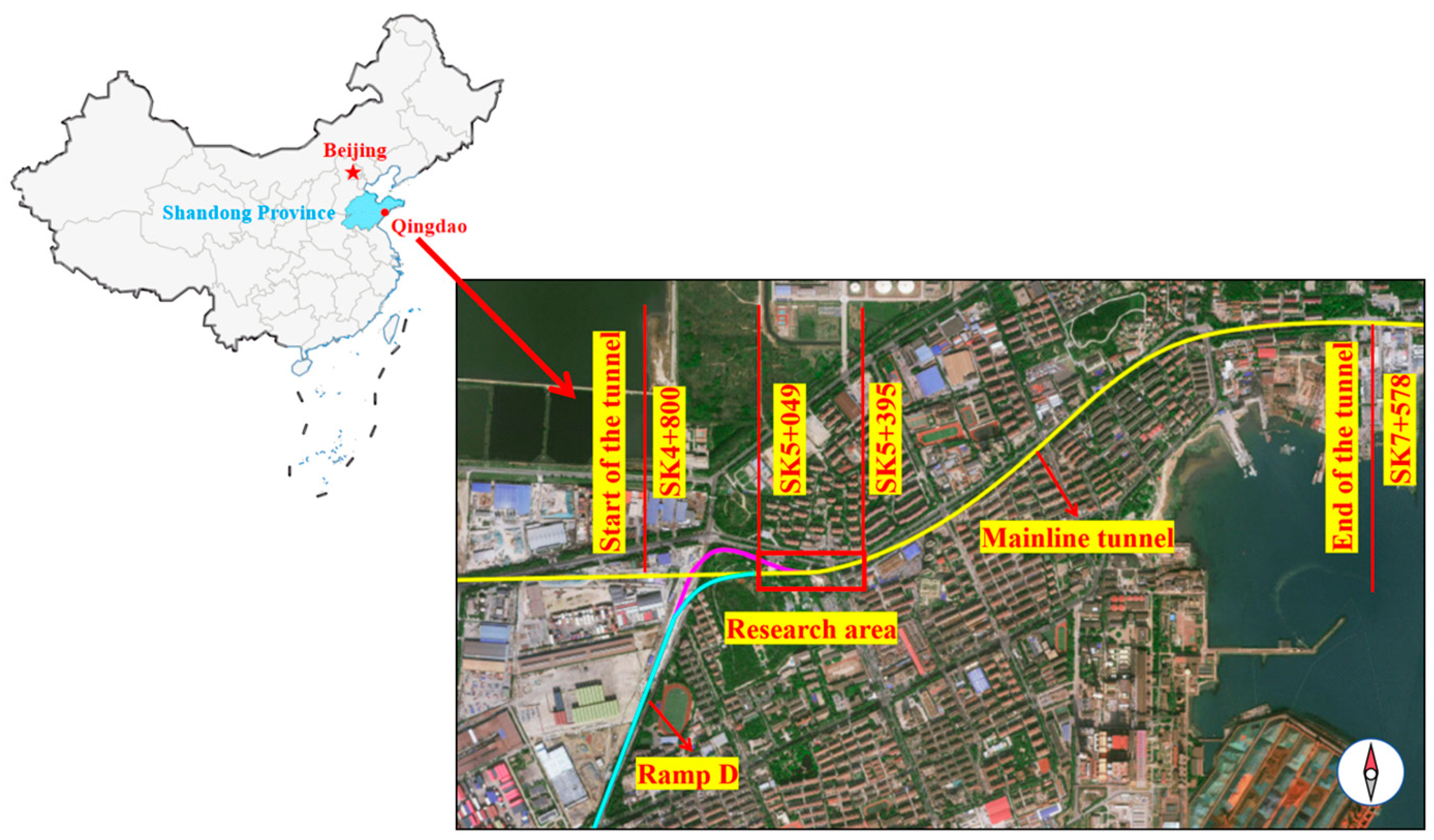
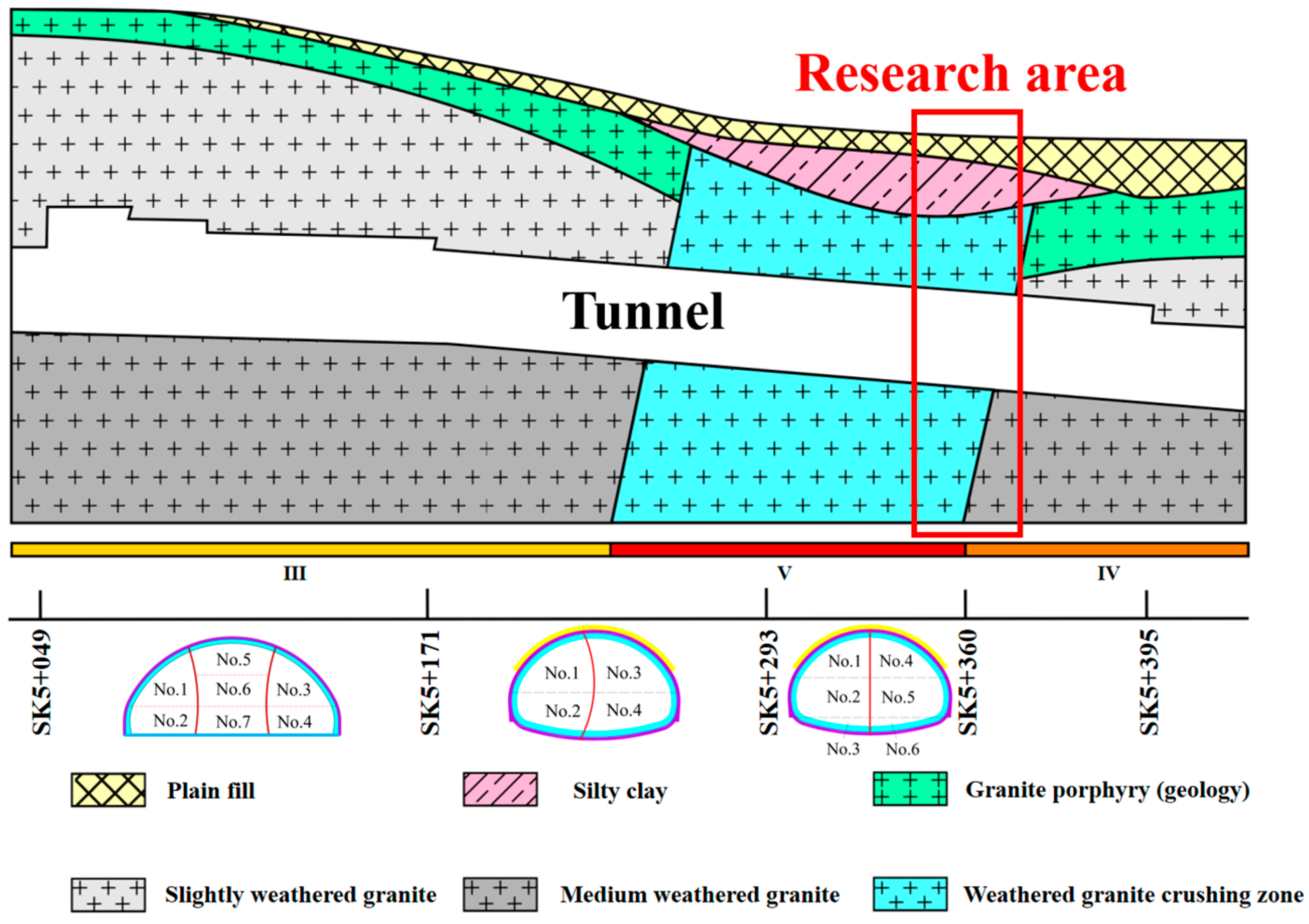
2.1. Geological Background

The Jiaozhou Bay Second Submarine Tunnel, situated in Qingdao, Shandong Province, China, serves as a pivotal connector between the eastern and western coastlines of the city. The Huangdao terrestrial segment of the tunnel is positioned in the urban core, where the Quaternary Loose Accumulation Layer is extensively distributed along the tunnel alignment, and the surrounding surface structures are highly intricate. A satellite imagery of the tunnel route is depicted in Figure 1.
The geological survey report shows that the geological conditions along the tunnel route are complex, crossing a weathered granite fracture zone. The geological section of the research area is shown in Figure 2, with the layers from top to bottom in the order of miscellaneous fill soil, silty clay, and weathered granite fracture zone.

2.2. Project Overview

The main line of the south tunnel intersects with Ramp D and enters the large-span tunnel construction section, the total length of the large-span tunnel area is 346 m, the starting and finishing mileage is SK5 + 049~SK5 + 395, the tunnel span in the research area is about 20.68 m, the tunnel section height is about 14.26 m, and the depth of the buried depth is about 15.00 m. Aiming at the geological conditions and environmental characteristics of the section, the engineering team chose the drill-and-blast method as the main construction method to ensure the safety of the construction method to ensure the safety of construction.
The tunnel passes through an eight-story frame building, which has an independent foundation with a depth of 3.70 m. The bottom of the foundation is 11.30 m from the top of the tunnel, and a weathered granite fracture zone is exposed below the building, with fissures developed in the rock—mainly sandy soil and blocky fractured rock. The shallow buried tunnel construction process has a greater impact on the surrounding buildings, ensuring the structural safety of the upper building is a major problem in the construction process.
In response to the dual risks of tunneling through existing buildings and crossing fault fracture zones, a series of pre-strengthening measures were taken prior to construction, including overrun pipe shed support and surface cuff valve tube grouting reinforcement, to enhance the stability of the tunnel surrounding rock, thereby reducing the safety risks during construction.

3. Numerical Simulations

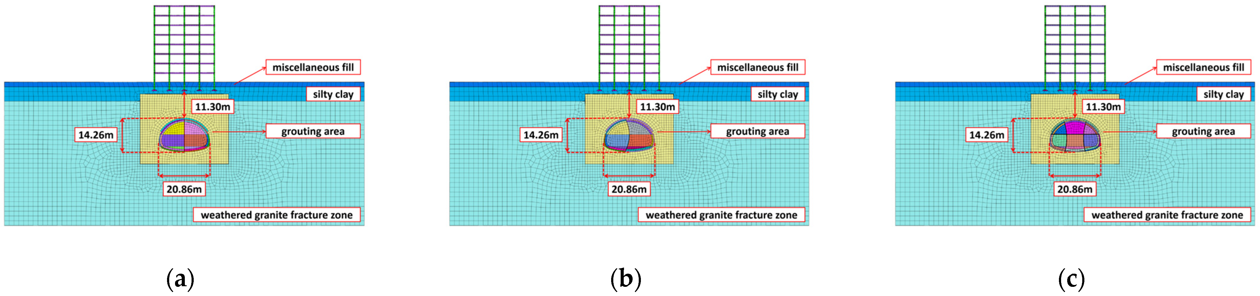
3.1. Description of the Numerical Model

Numerical simulation has become a crucial tool for addressing complex problems in geotechnical engineering. To further investigate the impact of a shallow buried tunnel on the stability of overlying frame-structured buildings, three types of numerical models were developed: the vertical support CD method, the curved support CD method, and the double side-wall guide pit method, as depicted in Figure 3.
Considering the extent of disturbance caused by tunnel excavation, the distance between the tunnel and the left and right boundaries of the model is set to be three times the tunnel’s excavation span. Additionally, the distance between the bottom of the tunnel and the lower boundary is twice the height of the tunnel.
The stratigraphic numerical model is 60 m high, 150 m wide, and 50 m long, and the stratum of the model is in order from top to bottom: plain fill, powdery clay, weathered granite fracture zone. Among them, the thickness of the soil fill layer is 2 m, the thickness of the powdery clay layer is 6 m, and the thickness of the weathered granite fracture zone is 52 m. The numerical model of the building is 25 m in length, 15 m in width, and 32 m in height, with eight floors above ground, and the height of the floors is 4 m. Underground is an independent foundation with a burial depth of 3.7 m. The surrounding rock of the tunnel is seriously crushed, and it adopts the surface cuff valve pipe slurring to reinforce it, and the model reserves the slurring reinforcement area, which is 10 m above the top of the tunnel. The scope of the grouting reinforcement area is 10 m above the top of the tunnel, 8 m on the left and right sides of the tunnel, and 5 m below the bottom of the tunnel.
Horizontal constraints are set on the left and right sides of the model, longitudinal constraints are set on the front and back sides of the model, vertical constraints are set on the bottom of the model, and the top is a free boundary.

3.2. Basic Assumption

  • The geotechnical material is a continuous, uniform, isotropic elastoplastic medium;
  • The initial stress field considers only self-weight;
  • An idealized model of the tunnel crossing directly underneath the building is developed.

3.3. Constitutive Model and Calculation Parameters

The Mohr–Coulomb principal model is a common model used to simulate the shear damage of soil and rock, which has a wide range of applications in geotechnical engineering. Therefore, the Mohr–Coulomb principal model is used for all the strata in this numerical simulation.
The elastic constitutive model is a kind of model based on elasticity theory to describe the elastic behavior of materials, which is suitable for materials whose stress–strain relationship conforms to the elasticity law and is widely used in geotechnical engineering for materials that hardly deform during loading and unloading. Therefore, all the beams, slabs, columns, foundations, and tunnel support structures of the building in this numerical simulation adopt the elastic constitutive model.
Calculation parameters are determined based on the design description of the Jiaozhou Bay Second Submarine Tunnel and related specifications such as engineering geological manual, and the parameters of steel arch frame and steel wire mesh in the initial support are discounted to the shotcrete in order to simplify the model and calculation process. Checking the relevant literature [22], it can be seen that the modulus of elasticity of the surrounding rock in the grouting reinforcement area is improved by 42–56%, the cohesion is improved by 35–51%, and the angle of internal friction is improved by 2.3–3.4°. In summary, the parameters of perimeter rock after grouting reinforcement in this numerical calculation are taken according to the increase in modulus of elasticity by 50%, the increase in cohesion by 40%, and the increase in internal friction angle by 3°.
The physio-mechanical parameters of the stratum for this numerical simulation are presented in Table 1, while those for the building and supporting structures are detailed in Table 2.

3.4. Excavation Simulation

As shown in Figure 4, the vertical support CD method and the curved support CD method divide the tunnel section into six guide pits, and the double side-wall guide pit method divides the tunnel section into nine guide pits.
1.
The vertical support CD method and the curved support CD method are divided into 17 specific construction phases.
Stages 1–3: Sequentially excavate the upper, middle, and lower steps (No. 1, No. 2 and No. 3) of the left guide hole, and apply initial supports in a timely manner, and set up temporary supports, each time the excavation feed is 2 m, and the staggered distance of excavation between each guide hole is 4 m.
Stages 4–6: Sequentially excavate the upper, middle, and lower steps (No. 4, No. 5 and No. 6) of the right guide hole, and apply initial supports in a timely manner, and set up temporary supports, each time the excavation feed is 2 m, and the staggered distance of excavation between each guide hole is 4 m.
Stages 7–12: No. 1–6 were penetrated in sequence, and initial supports and temporary supports were imposed to complete.
Stages 13–17: Removal of temporary supports and application of secondary lining, with 10 m of footage for each temporary support removal and secondary lining application.
2.
The double side-wall guided pit method is divided into 23 specific construction phases.
Stages 1–3: Sequentially excavate the upper, middle, and lower steps (No. 1, No. 2 and No. 3) of the left guide hole, and apply initial supports in a timely manner, and set up temporary supports, each time the excavation feed is 2 m, and the staggered distance of excavation between each guide hole is 4 m.
Stages 4–6: Sequentially excavate the upper, middle, and lower steps (No. 4, No. 5 and No. 6) of the right guide hole, and apply initial supports in a timely manner, and set up temporary supports, each time the excavation feed is 2 m, and the staggered distance of excavation between each guide hole is 4 m.
Stages 7–9: Sequentially excavate the upper, middle, and lower steps (No. 7, No. 8 and No. 9) of the center guide hole, and apply initial supports in a timely manner, and set up temporary supports, each time the excavation feed is 2 m, and the staggered distance of excavation between each guide hole is 4 m.
Stages 10–18: No. 1–9 were penetrated in sequence, and the initial supports and temporary supports were imposed to complete.
Stages 19–23: Removal of temporary supports and application of secondary lining, with 10 m of footage for each temporary support removal and secondary lining application.

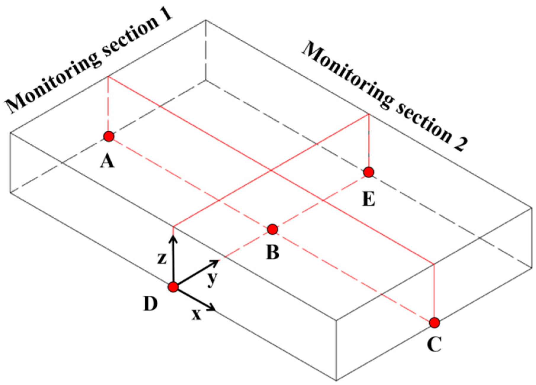
3.5. Layout of Monitoring Sections and Points

In this numerical simulation analysis, two rows of monitoring sections with a total of five monitoring points were set up to monitor the settlement and inclination of the building in the transverse and longitudinal directions, as shown in Figure 5. Among them, monitoring point A is the foundation of the left side of the building, monitoring point B is the foundation of the center of the building, monitoring point C is the foundation of the right side of the building, monitoring point D is the foundation of the front side of the building, and monitoring point E is the foundation of the back side of the building.

3.6. Analysis of Model Validity

Numerical results and monitoring results are shown in Figure 6. The settlement of each measurement point of the field surface was compared and analyzed with the numerical calculation of the settlement value in this research. The general deformation trend is the same, and taking into account the limitations of the field measurement, data are difficult to collect continuously, compared with a single settlement value. It is found that the calculation results and the field measurement value have a certain gap. Combined with the site of the complex construction environment, the error is within the controllable scope of the validation of the obtainable numerical value. The calculation results are basically in line with the field construction deformation law and have a certain reference value.

4. Numerical Results

In order to analyze the impact of shallow buried tunnel penetration on the stability of the overlying buildings, this paper carries out detailed numerical calculations and analyses of the ground surface and building displacement fields, which can directly reflect the impact of shallow buried tunnel penetration on the stability of the overlying buildings through the changes in the ground surface and building displacement fields.

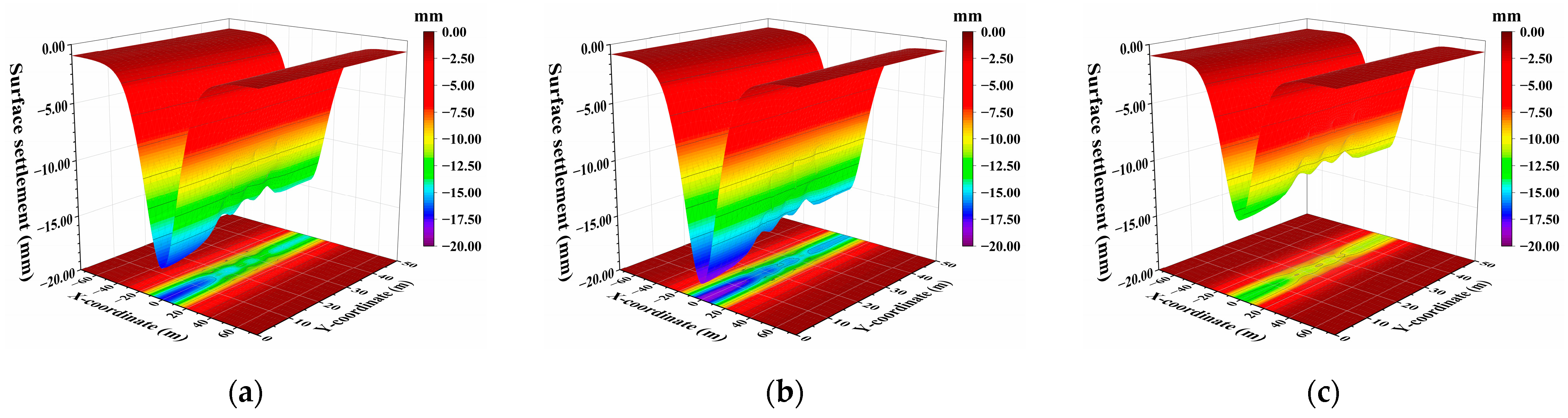
4.1. Characteristics of Surface Settlement

Figure 7 clearly demonstrates that the surface settlement follows a distinct U-shaped curve under the three working conditions, peaking at the tunnel centerline and then gradually decreasing toward both sides. Among the three methods, the curved support CD method results in the most significant surface settlement, reaching a maximum of 19.00 mm. The vertical support CD method yields slightly lower settlements, with a maximum of approximately 17.00 mm, which is 10.53% less than that of the curved support CD method, demonstrating a more pronounced improvement in surface settlement control. The double side-wall guide pit method proves to be more effective, with a maximum settlement value of about 13.00 mm, representing a 31.58% reduction compared to the curved support CD method. This indicates that the double side-wall guide pit method offers significant advantages in mitigating surface settlement.
As the excavation distance continues to increase, the overall surface settlement along the tunnel centerline is continuously decreasing. It is analyzed that the timely installation of support in the earlier excavated sections of the tunnel has reduced the exposure time of the surrounding rock, mitigated the inducing effect of the free face on the deformation of the surrounding rock during tunnel construction, and the excellent strength of the support structure has enhanced the overall stability of the tunnel. This provides a more stable working environment for subsequent tunnel excavation. As the tunnel advances, the previously supported sections provide a solid foundation for ongoing construction, thereby reducing the settlement risk of newly excavated sections.
Along the direction of tunnel excavation, there are several areas along the tunnel centerline where the surface settlement decreases sharply. It is analyzed that this reduction is due to the positive role played by the independent foundations of buildings in resisting the disturbance of tunnel excavation. These foundations evenly distribute the load transferred from the upper structure, avoiding the occurrence of localized stress concentrations. At the same time, they provide additional support force, helping to maintain the stability of the surrounding soil. This reduces the deformation and settlement of the soil caused by tunnel excavation, thereby making the overall settlement value of the buildings less than that of the surrounding surface area [23].

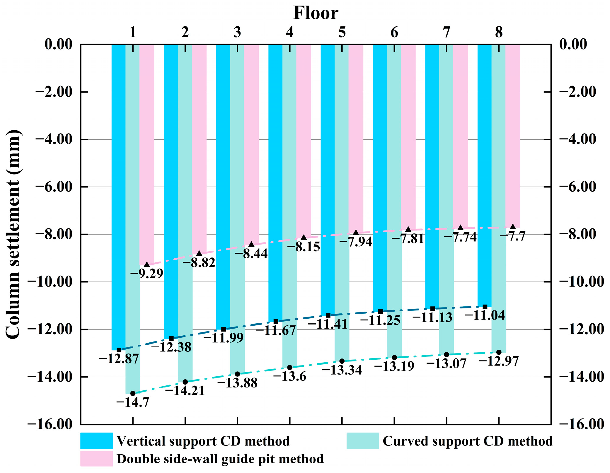
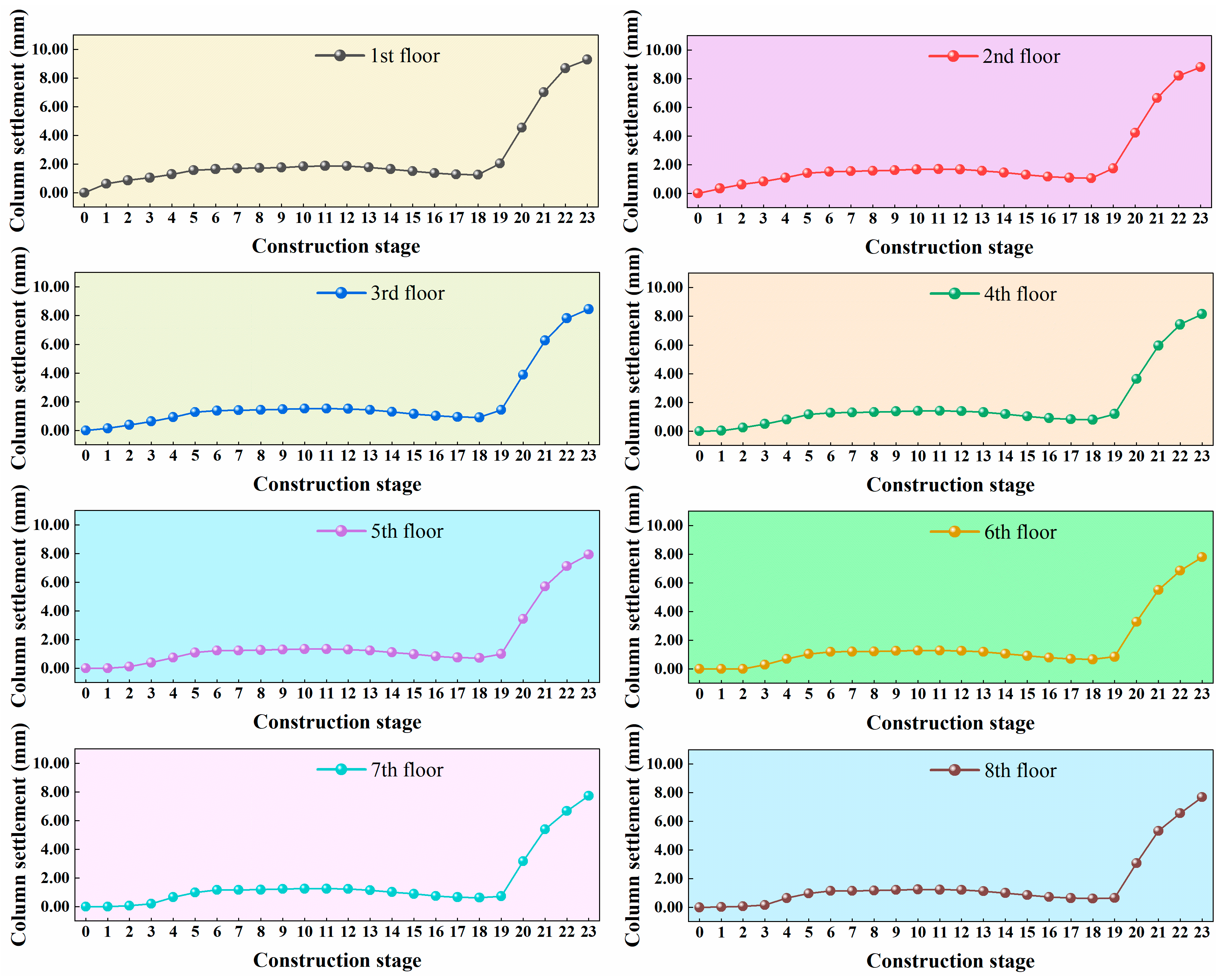
4.2. Characteristics of Building Displacement

As can be seen from Figure 8, after tunnel excavation through the building using the vertical support CD method, the settlement of the building shows a distribution trend of being maximum at the center and gradually decreasing towards both sides, which coincides with the general trend of surface settlement. When comparing the effects of the three different excavation methods on the building’s settlement, it can be observed that the maximum displacement of the building in all methods occurs at the foundation, corresponding to the center column.
Specifically, the curved support CD method of excavation resulted in the most significant displacement of 15.08 mm, and this large settlement deformation could potentially lead to building destruction and the expansion of cracks. In contrast, the maximum displacement caused by the vertical support CD method of excavation was 13.32 mm, which was reduced by 11.67% compared to the curved support CD method. The maximum displacement caused by the double side-wall guided pit method was 9.72 mm, which is 35.54% lower compared to the curved support CD method, and this significant reduction indicates that the double side-wall guided pit method has significant advantages in controlling the settlement of the building.
Since Figure 8 can only reflect the overall settlement trend of the building and cannot visually display the vertical settlement pattern, the settlement values of the center frame columns for each floor of the building were extracted and are shown in Figure 9. After the shallow buried tunnel with three different excavation methods passes through the building, the settlement trend of the center frame columns for each floor is consistent: the largest settlement occurs on the bottom floor, the smallest on the top floor, with the settlement gradually decreasing from the bottom to the top. Taking the curved support CD method, which has the largest settlement as an example, the settlement value of the bottom layer is the greatest, at approximately 14.70 mm, while the settlement value of the top layer is the smallest, at approximately 12.97 mm. The settlement difference between the bottom and top layers is about 1.73 mm, and the average settlement difference between the layers is about 0.22 mm.
The settlement value of the bottom layer of the building frame columns using the vertical support CD method was about 12.87 mm, which was 12.45% less than that of the curved support CD method. The settlement value of the top layer was about 11.04 mm, which was 14.88% less than that of the curved support CD method. The difference in settlement between the bottom layer and the top layer was about 1.83 mm, which was 5.78% more than that of the curved support CD method. The average difference in settlement value between the layers was about 0.23 mm, which was 4.55% more than that of the curved support CD method.
The settlement value of the bottom layer of the building frame columns using the double side-wall guide pit method was about 9.29 mm, a reduction of 36.80% compared to the curved support CD method. The settlement value of the top layer was about 7.67 mm, a reduction of 40.86% compared to the curved support CD method. The settlement difference between the bottom layer and the top layer was about 1.62 mm, a reduction of 6.36% compared to the curved support CD method. The average settlement difference value between the layers was about 0.20 mm, a reduction of 9.09% compared to the curved support CD method.
In terms of the overall settlement of the building, both the vertical support CD method and the double side-wall guide pit method perform better than the curved support CD method. Regarding the uniformity of building settlement, the double side-wall guide pit method still outperforms the curved support CD method. However, the average settlement difference between the layers of the vertically supported CD method increases slightly compared to the curved support CD method, which is not conducive to the overall stability of the building.
As depicted in Figure 10, the frame columns at each level exhibit the same trend of change throughout the tunnel construction process. Throughout the dynamic change process, the settlement of the frame columns at each level consistently shows the maximum settlement at the bottom level and the minimum at the top level. The settlement curves of the frame columns at each level during the excavation process tend to flatten out as a whole until the removal of the temporary support, which results in the settlement values of the frame columns at each level of the building doubling. Therefore, it is crucial to pay attention to the timing of temporary support removal and secondary lining application to minimize the exposure time of the initial support.

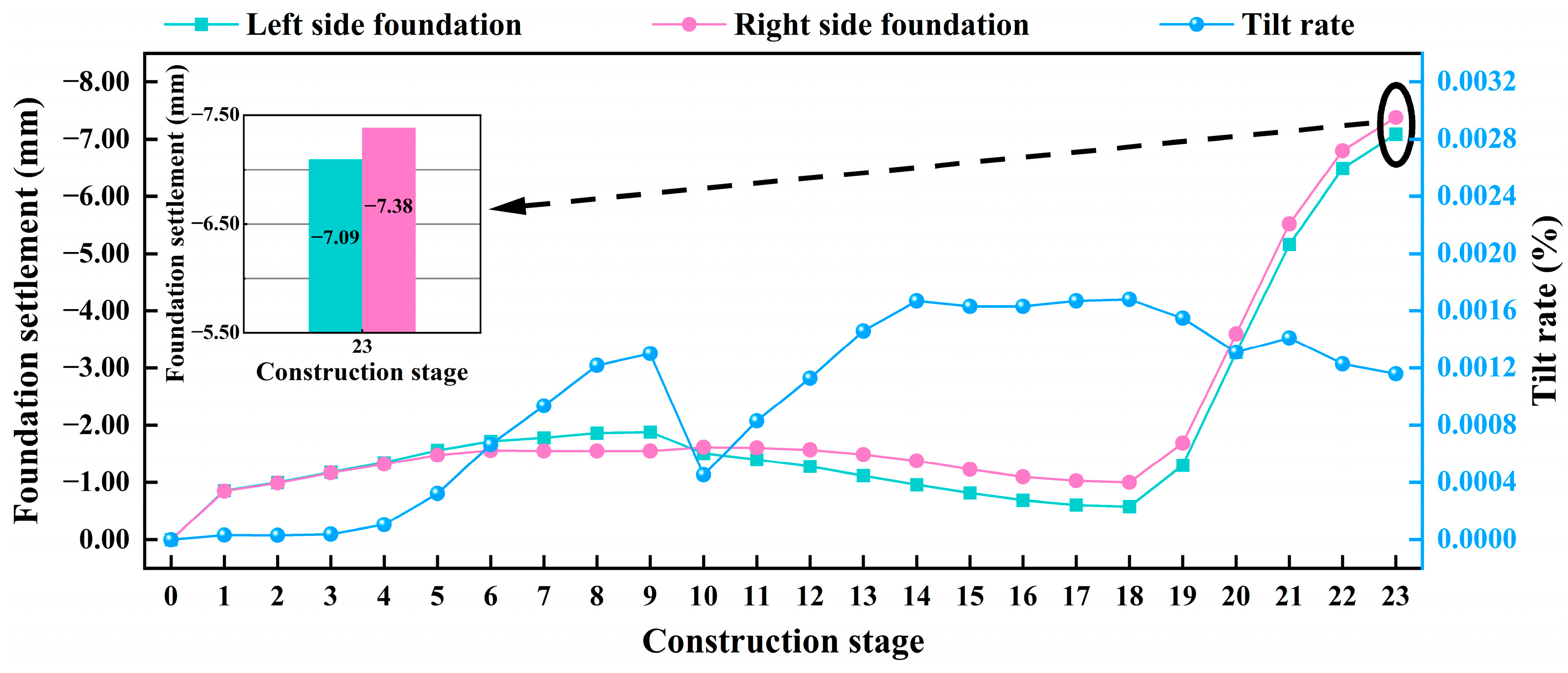
4.3. Laws of Dynamic Changes in Building Tilt Rate

A review of the literature shows that settlement analyses of multi-story frame buildings are usually carried out by comparing the overall building tilt [18]. The overall building inclination rate is the ratio of the settlement difference between the foundations of a building to the distance between two points [24].
The lateral dynamic tilt rate of the building constructed using the double side-wall guide pit method is shown in Figure 11.
Stages 1–3: Influenced by the excavation disturbance of Tunnel No. 1, 2, and 3, the left foundation settlement and the right foundation settlement showed the same gently rising trend, and the left foundation settlement was slightly higher than the right foundation settlement. The building was tilted to the left side.
Stages 4–9: From stage 4, the overall tilt rate of the building was greatly improved. At this time, No. 4 started digging, No. 1 was dug 14 m, and the distance from the left side foundation monitoring point was shortened to 11 m, and the left side foundation became greatly affected by the excavation of No. 1, 2, and 3. In addition, the settlement difference with the right side foundation gradually increased, and the overall tilt rate was continuously improved, which lasted to stage 9.
Stage 10: Excavation of No. 1 was completed, the influence of the left guide hole excavation disturbance on the stability of the building was weakened, and the support structure of the left guide hole was stable, while the right guide hole lagged behind the left guide hole by 12 m. At this time, the excavation disturbance of the right guide hole had a greater influence on the right foundation, and the settlement value of the right foundation exceeded that of the left foundation, and the building tilted to the right side.
Stages 11–14: Excavation of No. 2 and No. 3 was completed sequentially. At this time, the left guide hole was fully constructed, and then the excavation of No. 4 and No. 5 was completed sequentially, and the tilt rate of the building increased due to the influence of the excavation disturbance of the right guide hole until No.6 was passed through.
Stages 15–18: Excavation of No. 6, 7, 8, 9 was completed sequentially, at which time the change in the tilt rate of the building became smoother.
Stages 19–23: Temporary supports were removed and the secondary lining applied at a rate of 10 m per stage, with rapid and simultaneous increases in settlement of the left and right foundations of the tunnel, and an overall decreasing rate of inclination of the tunnel.
The longitudinal dynamic tilt rate of the building constructed using the double side-wall guide pit method is shown in Figure 12.
Stages 1–9: With the excavation of No. 1–9, the settlement of the front side foundation and the rear side foundation of the building increased gently. The front side foundation became closer to the excavation surface, which was more affected by the excavation disturbance, and the settlement difference with the rear side foundation also increased gradually. The tilt rate of the building increased gradually, and the building as a whole became tilted forward, which is consistent with the trend of surface settlement.
Stages 10–15: In stage 10, the No. 7 guide hole was excavated to 26 m, which passed through the front side foundation monitoring point. The tilt rate of the building reached the local peak, and the tilt rate of the building gradually decreased in the latter stages of 11–15. The analyses shows that, due to the fact that the building excavation surface gradually became closer to the rear side foundation monitoring point at this time, the disturbance influence on the rear side foundation was higher than the front side foundation, so that the settlement difference between the two shrank continuously. It is analyzed that, as the building excavation surface gradually approached the rear side foundation monitoring point at this time, the disturbance influence on the rear side foundation became higher than that on the front side foundation, so that the settlement difference between the two decreased.
Stages 16–18: At this point, the tunneling work was coming to an end and the tilt rate of the building began to level off.
Stages 19–20: The removal of the temporary support for the tunnel under the front side foundation impacted on the stability of the front side foundation, resulting in a significant increase in the settlement of the front side foundation and a rapid increase in the tilt rate. The longitudinal tilt rate peaked at this stage, and the construction risk became high.
Stages 21–23: The temporary support of the tunnel under the back side foundation was removed so that the settlement growth rate of the back side foundation became higher than that of the front side foundation, which reduced the settlement difference between the two, and the tilt rate decreased rapidly.
The relevant provisions of the Code for the measurement of building deformation are shown in Table 3 [24]. Here, l represents the center-to-center distance of adjacent foundations, with the unit being millimeters (mm), and Hg representing the height of the building measured from the ground. According to Table 3, the differential settlement of the building foundation should not exceed 0.002 times the center-to-center distance of adjacent foundations, and the allowable value for this model is 12.5 mm. The height of the building is 32 m, and the tilt rate is 0.3%. After verification, all the above conditions meet these requirements.
From the above numerical results, the double side-wall guide pit method is superior to both the vertically supported CD method and the curved supported CD method in controlling the deformation behavior of both the ground surface and the building. Among these, the vertical support CD method, benefiting from its vertical support form, exhibits better control over the deformation of the ground surface and the building than the curved support CD method. Furthermore, in the dynamic deformation of the building demonstrated by the double side-wall guided pit method, it is observed that the settlement and tilt risk during the temporary support removal stage is more significant than in other construction stages. Therefore, deformation control research in this stage should be a focus and carried out with priority.

5. Laws of Stress Relief on Building Deformation

In the in-depth analysis of the settlement and tilting of buildings under various working conditions, a common phenomenon can be observed: during the stage of removing the temporary support structure, the settlement and tilting of the building’s foundation tend to suddenly intensify. To effectively control this phenomenon, the proportion of stress relief when removing the temporary support must be carefully controlled. This paper investigates the stability change rules of the building under different stress relief states by setting up three kinds of stress relief rates: 30%, 50%, and 100%. Through meticulous management of this process, it can effectively reduce the settlement and tilting problems that may occur in the later stages of construction, ensuring the stability and safety of the structure.

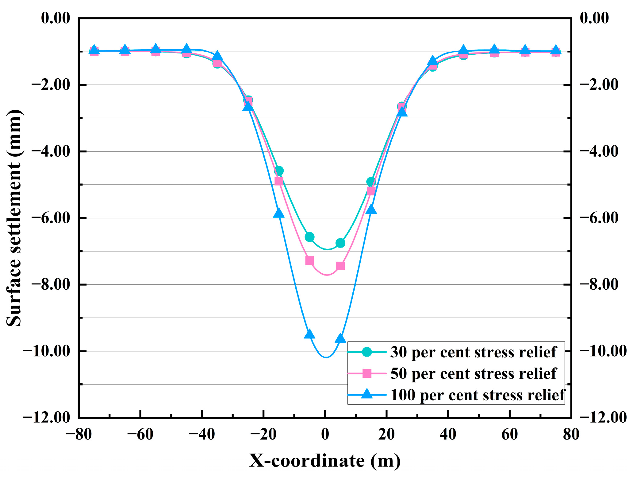
5.1. Surface Settlement for Different Stress Relief States

From Figure 13, it can be clearly observed that under the three working conditions, the surface settlement exhibits a distinct U-shaped characteristic, decreasing gradually from the centerline to both sides. By controlling the proportion of stress release during the temporary support removal phase in tunnel construction, the peak value and the influence range of surface settlement can be effectively managed.

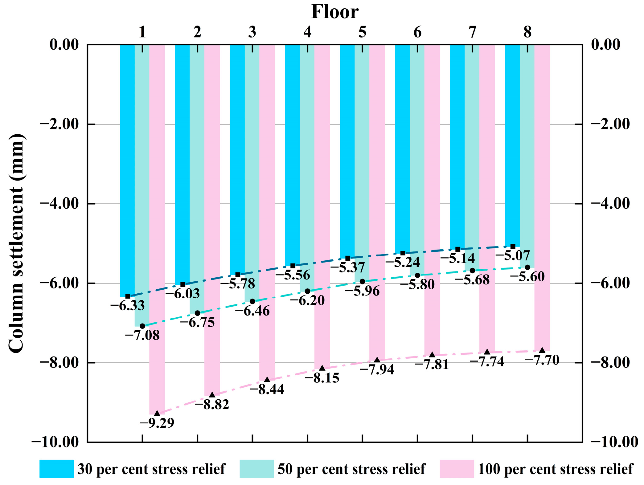
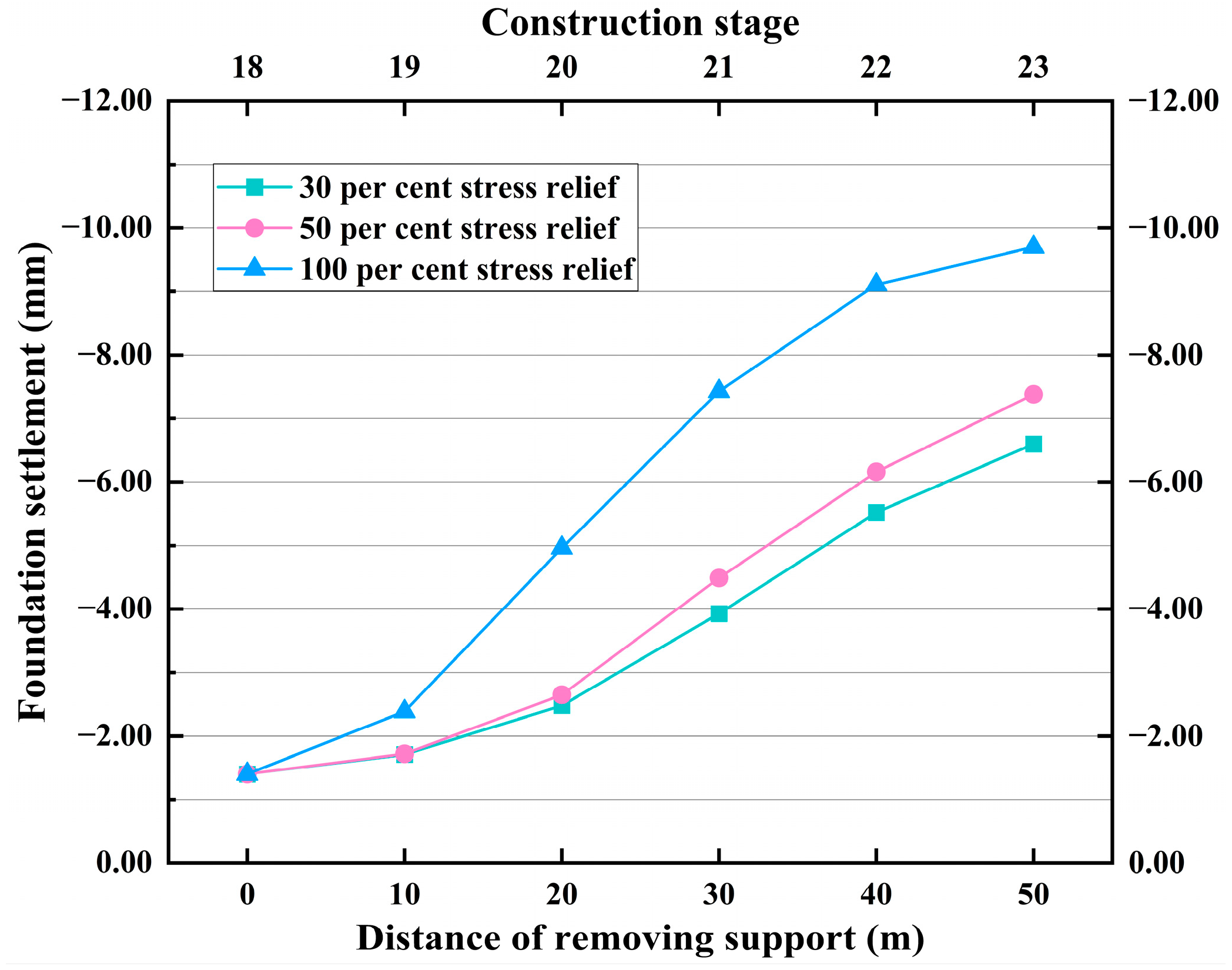
5.2. Dynamic Settlement of Buildings with Different Stress Relief States

As shown in Figure 14 and Figure 15, the maximum settlement value of the building frame columns under the state of complete stress relief is 9.29 mm, and the average settlement difference between layers is 0.20 mm. Under the state of 30% stress relief, the maximum settlement value of the building frame columns is 6.33 mm, which is 31.86% lower than that under the state of complete stress relief, and the average settlement difference between layers is 0.16 mm, which is 20.00% lower than that under the state of complete stress relief. Under the 50% stress relief condition, the maximum settlement of the building frame columns is 7.08 mm, which is 23.79% lower than the stress fully relieved condition, and the average settlement difference between floors is 0.19 mm, which is 5.00% lower than the stress fully relieved condition.
As shown in Figure 16, the final settlement of the building foundation is 9.70 mm under complete stress relief. Under 30% stress relief, the final settlement is 6.60 mm, which is 31.96% lower than under complete stress relief. Under 50% stress relief, the final settlement is 7.38 mm, which is 23.92% lower than under complete stress relief.

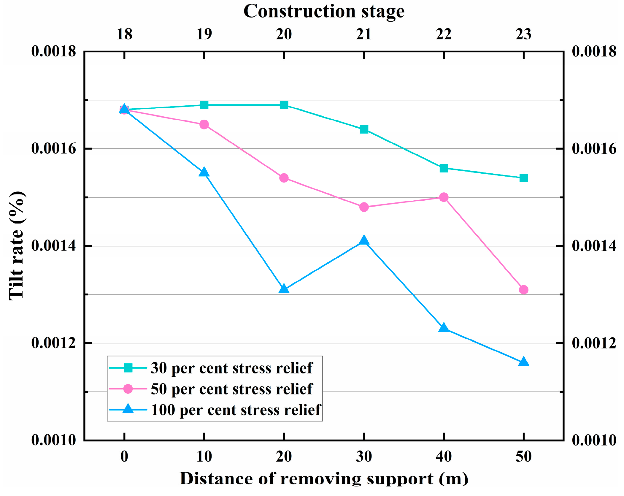
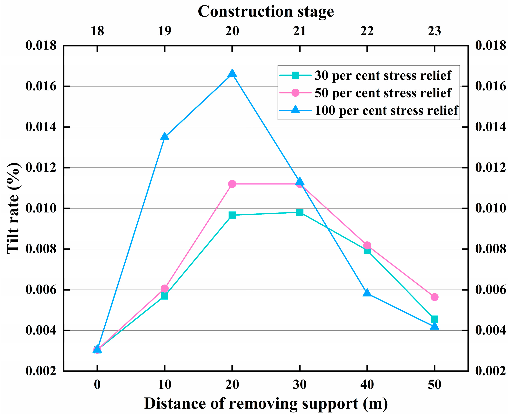
5.3. Dynamic Tilt Rate of Buildings with Different Stress Relief States

As shown in Figure 17, with the sequential removal of the temporary support, the settlement values of the left and right foundations increased continuously, while the settlement difference between the two foundations fluctuated less, and the lateral tilt rate of the building gradually decreased. The results show that the final lateral tilt rate increases by 32.76% under the 30% stress relief condition compared with the full stress relief condition, and the final lateral tilt rate increases by 12.93% under the 50% stress relief condition compared with the full stress relief condition. Combined with Figure 16, it can be found that as the proportion of stress relief increases, the lateral tilt rate of the building decreases gradually, but the settlement of the building increases continuously.
As shown in Figure 18, the longitudinal tilt rate under the fully stress-relieved condition reaches its peak at stage 20, while the longitudinal tilt rates of the remaining two conditions with controlled stress relief are much smaller than that of the fully stress-relieved condition at this stage. Combined with the dynamic foundation settlement change curves in Figure 16, it can be observed that by controlling the proportion of stress relief during the temporary support removal stage, the impact of the temporary tunnel support removal on the settlement of the overlying building’s foundation can be effectively reduced, achieving the goal of controlling the longitudinal tilt rate of the building. The results indicate that the final longitudinal tilt rate increased by 9.10% under the 30% stress relief condition compared to the fully stress-relieved condition, and by 34.93% under the 50% stress relief condition compared to the fully stress-relieved condition.

6. Discussion

In this research, the influence of shallow buried tunnel crossings on the stability of overlying frame buildings is analyzed. As the tunnel construction proceeds, the deformation area and deformation amount of the ground surface and buildings are constantly changing dynamically. The tunnel excavation disturbances rapidly extend to the ground surface and alters the ground surface and building settlement. The vertical deformation mainly occurs in the building foundation and the ground surface area above the center line of the tunnel, with the maximum settlement of the building foundation of about 9.70 mm and the maximum settlement of the ground surface of about 13.00 mm. By comparing the differences between the numerical results and the monitoring results at some of the monitoring points, it can be seen that the maximum difference between the numerical calculations and the monitoring results is about 1.35 mm, and the difference is only 9.43 per cent of the monitoring results.
Numerical simulation results show that the double side-wall guided pit method has significant advantages in terms of surface settlement and building deformation control. Compared with the vertical or curved support CD method, the double side-wall guide pit method also has significant disadvantages. This is due to the fact that the double side-wall guide pit method has more guide holes, which are relatively small. The mechanical equipment and slag transport efficiency are low, and there is reciprocal disturbance to the horizontal temporary support. This is not conducive to the stability of the upper guide holes and, consequently, the stability of the overlying buildings. These factors cannot be fully reflected in the numerical simulation process. At the same time, this is one of the important factors for the deviation of the monitoring results from the numerical results.
A common phenomenon can be found in the process of analyzing the above working conditions: during the stage of removing the temporary support structure, the foundation settlement and tilt of the building tends to increase suddenly. Therefore, this research considers analyzing from the point of view of controlling the stress relief rate during the temporary support removal stage. The results show that a smaller stress release state helps to reduce the impact of the tunnel construction disturbance on the foundation, which has a significant advantage in surface and building settlement control. In the 30% stress relief condition, the maximum settlement of the building foundation is about 6.60 mm, which is 31.96% lower than that in the full stress relief condition. In addition, the smaller stress relief condition can better control the peak longitudinal tilt rate during the construction process and reduce the risk of building tilt.
There are some limitations to this research. This study simulates fault fracture zones by discounting the rock strength, which does not show the effects of the complex structure and discontinuities of fault fracture zones. This study does not consider reinforced foundations as a solution to maintain building stability and also ignores the effect of lateral thrust on building stability. Additionally, the research has only examined surface and building displacements, without analyzing the interaction between the tunnel and building displacement fields or their synergistic change mechanisms. In view of the above deficiencies, it is planned to use deep learning method to consider the influence of stratum spatial variability on the numerical results in the future research, to establish a random field of perimeter rock parameters based on the Karhunen-Loeve method, and to supplement the hypothetical conditions more comprehensively in order to more realistically reproduce the actual construction scene. This research has deeply explored the influence mechanism of shallow-buried tunnel crossings on the stability of the frame structure buildings above, revealed its action laws, and provided valuable references for the construction of shallow buried tunnels in urban areas, which holds significant engineering application value.

7. Conclusions

(1) Numerical simulation analysis reveals a consistent trend of surface and building settlement for the three excavation conditions: the settlement value gradually decreases from the centerline of the tunnel to both sides. Compared with the vertical or curved support CD method, the double side-wall guided pit method of tunneling can minimize the impact of disturbance on the overlying frame building, and at the same time ensure that the surface settlement and building deformation are within the safety control standards.
(2) From the numerical results of surface settlement, it is evident that the timely installation of support structures can reduce the exposure time of the tunnel’s peripheral rock and alleviate the induced deformation of the peripheral rock on the free surface during the tunnel construction process. Additionally, the excellent strength of the support structures also enhances the overall stability of the tunnel.
(3) Comparing the numerical results of surface settlement and building foundation settlement, it is observed that the independent foundation of the building plays a positive role in resisting the disturbance caused by tunnel excavation. It evenly disperses the load, avoids stress concentration, and reduces the overall settlement of the building. Consequently, the settlement of the building is slightly lower than that of the surrounding surface.
(4) Temporary supports play a crucial role in stability control during the tunnel construction process. The removal of these temporary supports significantly impacts all three excavation methods, causing substantial settlement of the tunnel vault and the ground surface above it, as well as the buildings. This stage also has a significant impact on the longitudinal tilt rate of the buildings. For instance, in the case of the double side-wall guide pit method, the peak of the longitudinal tilt rate reached 1.66 × 10⁻²% during the removal of the temporary support below the building foundations, which is about fourtimes the final longitudinal tilt rate.
(5) Adjusting the stress relief state during the temporary support removal stage is a key method to ensure the stability of the overlying frame structure building. In the 50% stress relief state, the maximum settlement of the building foundation is reduced by 23.92%, and in the 30% stress relief state, it is reduced by 31.96%. Additionally, the tilt rate peaks during the dynamic construction process are controlled, which reduces the risk of settlement and tilt for the building.

Author Contributions

Conceptualization, S.J. and J.Q.; methodology, B.W. and H.G.; software, B.W. and M.H.; validation, B.W., M.H. and C.L.; formal analysis, C.L.; investigation, B.W.; resources, Z.Q.; data curation, Z.Q.; writing—original draft preparation, B.W.; writing—review and editing, S.J.; visualization, B.W.; supervision, M.H.; project administration, J.Q.; funding acquisition, B.W. All authors have read and agreed to the published version of the manuscript.

Funding

This research received no external funding.

Institutional Review Board Statement

Not Applicable.

Informed Consent Statement

Informed consent was obtained from all subjects involved in the study.

Data Availability Statement

The original contributions presented in this study are included in the article. Further inquiries can be directed to the corresponding author.

Conflicts of Interest

The authors declare no conflict of interest.

References

  1. Khabbaz, H.; Gibson, R.; Fatahi, B. Effect of Constructing Twin Tunnels under a Building Supported by Pile Foundations in the Sydney Central Business District. Undergr. Space 2019, 4, 261–276. [Google Scholar] [CrossRef]
  2. Peck, R.B. Deep excavation and tunnelling in soft ground. In Proceedings of the 7th International Conference on Soil Mechanics and Foundation Engineering (Mexico) 7th ICSMFE, Mexico City, Mexico, 1969; pp. 225–290. [Google Scholar]
  3. Pinto, F.; Whittle, A.J. Ground Movements due to Shallow Tunnels in Soft Ground. I: Analytical Solutions. J. Geotech. Geoenvironmental Eng. 2014, 140, 04013040. [Google Scholar] [CrossRef]
  4. Pinto, F.; Zymnis, D.M.; Whittle, A.J. Ground Movements due to Shallow Tunnels in Soft Ground. II: Analytical Interpretation and Prediction. J. Geotech. Geoenvironmental Eng. 2014, 140, 04013041. [Google Scholar] [CrossRef]
  5. Yu, L.; Zhang, D.; Fang, Q.; Xu, T.; Luo, J.; Chen, W. Semi-Analytical Solutions of Three-Dimensional Ground Movements Due to Shallow Tunnelling. Tunn. Undergr. Space Technol. 2023, 136, 105074. [Google Scholar] [CrossRef]
  6. Zhao, C.; Lavasan, A.A.; Barciaga, T.; Schanz, T. Mechanized Tunneling Induced Ground Movement and Its Dependency on the Tunnel Volume Loss and Soil Properties. Int. J. Numer. Anal. Methods Géoméch. 2019, 43, 781–800. [Google Scholar] [CrossRef]
  7. Lu, D.; Kong, F.; Du, X.; Shen, C.; Gong, Q.; Li, P. A Unified Displacement Function to Analytically Predict Ground Deformation of Shallow Tunnel. Tunn. Undergr. Space Technol. 2019, 88, 129–143. [Google Scholar] [CrossRef]
  8. Xue, Y.; Gong, H.; Kong, F.; Yang, W.; Qiu, D.; Zhou, B. Stability Analysis and Optimization of Excavation Method of Double-arch Tunnel with an Extra-Large Span Based on Numerical Investigation. Front. Struct. Civ. Eng. 2021, 15, 136–146. [Google Scholar] [CrossRef]
  9. Giardina, G.; DeJong, M.J.; Mair, R.J. Interaction Between Surface Structures and Tunnelling in Sand: Centrifuge and Computational Modelling. Tunn. Undergr. Space Technol. 2015, 50, 465–478. [Google Scholar] [CrossRef]
  10. Ritter, S.; Giardina, G.; DeJong, M.J.; Mair, R.J. Influence of Building Characteristics on Tunnelling-Induced Ground Movements. Geotech. 2017, 67, 926–937. [Google Scholar] [CrossRef]
  11. Ritter, S.; Giardina, G.; DeJong, M.J.; Mair, R.J. Centrifuge Modelling of Building Response to Tunnel excavation. Int. J. Phys. Model. Geotech. 2018, 18, 146–161. [Google Scholar] [CrossRef]
  12. Ritter, S.; Giardina, G.; Franza, A.; DeJong, M.J. Building Deformation Caused by Tunneling: Centrifuge Modeling. J. Geotech. Geoenvironmental Eng. 2020, 146, 04020017. [Google Scholar] [CrossRef]
  13. Hong, X.; Zhang, D.; Zhou, M.; Fang, Q.; Hou, Y.; Fang, H.; Sun, Z. Approximate Analytical Solution of Tunneling-Induced Responses of a Soil–Foundation System Using Contact Mechanics. Int. J. Numer. Anal. Methods Géoméch. 2022, 46, 3442–3464. [Google Scholar] [CrossRef]
  14. Xu, J.; Franza, A.; Marshall, A.M.; Losacco, N.; Boldini, D. Tunnel–Framed Building Interaction: Comparison Between Raft and Separate Footing Foundations. Géotechnique 2021, 71, 631–644. [Google Scholar] [CrossRef]
  15. Mylonakis, G.; Gazetas, G. Seismic soil-structure interaction: Beneficial or detrimental? J. Earthq. Eng. 2000, 4, 277–301. [Google Scholar] [CrossRef]
  16. Savvides, A.-A. On the Numerical Investigation of the Absorbing Boundaries Influence to the Dynamic Soil Structure Interaction. Arab. J. Sci. Eng. 2024, 49, 13957–13973. [Google Scholar] [CrossRef]
  17. Gong, C.; Ding, W.; Xie, D. Twin EPB Tunneling-Induced Deformation and Assessment of a Historical Masonry Building on Shanghai Soft Clay. Tunn. Undergr. Space Technol. 2020, 98, 103300. [Google Scholar] [CrossRef]
  18. Cai, L.; Shi, K.; Jiang, F.; Chen, G.; Xiao, Z.; Zheng, C.; Zhang, S.; Wu, Y. Research on the Deformation Laws of Buildings Adjacent to Shield Tunnels in Clay Strata. Sci. Rep. 2024, 14, 265. [Google Scholar] [CrossRef]
  19. Zhang, D.; Li, P.; Hou, Y.; Fang, Q. Influence Due to Urban Tunnel Excavation on Ground Buildings and Its Countermeasures. Chin. J. Geotech. Eng. 2010, 32, 296–302. (In Chinese) [Google Scholar]
  20. Feng, X.; Hou, D.; Huang, Z. The Influence of Shield Tunneling Characteristics on the Safety of Buildings Above-Case Study for Shanghai Zone. Sustainability 2022, 14, 13391. [Google Scholar] [CrossRef]
  21. Sirivachiraporn, A.; Phienwej, N. Ground Movements in EPB Shield Tunneling of Bangkok Subway Project and Impacts on Adjacent Buildings. Tunn. Undergr. Space Technol. 2012, 30, 10–24. [Google Scholar] [CrossRef]
  22. Chen, J.; Li, Z. Research on optimization of pipe support parameters for shallow buried and small clear distance tunnels under unequal pressure. J. Hebei Univ. Eng. (Nat. Sci. Ed.) 2024, 41, 59–70. (In Chinese) [Google Scholar]
  23. Zhang, Y.; An, X.; Jin, Y. Centrifugal model tests on settlement of structures caused by tunnel excavation. Chin. J. Geotech. Eng. 2022, 44, 54–57. (In Chinese) [Google Scholar]
  24. Ministry of Housing and Urban Rural Development of the People’s Republic of China. Code for Deformation Measurement of Building and Structure JGJ8-2016; Construction Industry Press: Beijing, China, 2016.
Figure 1. Geographical location of the research area.
Jmse 12 02244 g001
Figure 2. Geological stratigraphic section of the research area.
Jmse 12 02244 g002
Figure 3. Tunnel calculation model: (a) Vertical support CD method; (b) Curved support CD method; (c) Double side-wall guide pit method.
Jmse 12 02244 g003
Figure 4. Division of the tunnel section: (a) Vertical support CD method; (b) Curved support CD method; (c) Double side-wall guide pit method.
Jmse 12 02244 g004
Figure 5. Layout of monitoring sections and points.
Jmse 12 02244 g005
Figure 6. Comparison of numerical results with monitoring results.
Jmse 12 02244 g006
Figure 7. Comparison of surface settlement: (a) Vertical support CD method; (b) Curved support CD method; (c) Double side-wall guide pit method.
Jmse 12 02244 g007
Figure 8. Vertical displacement of the building: (a) Vertical support CD method; (b) Curved support CD method; (c) Double side-wall guide pit method.
Jmse 12 02244 g008
Figure 9. Comparison of settlement in building frame columns.
Jmse 12 02244 g009
Figure 10. Dynamic settlement of building frame columns.
Jmse 12 02244 g010
Figure 11. Lateral tilt rate of the building.
Jmse 12 02244 g011
Figure 12. Longitudinal tilt rate of the building.
Jmse 12 02244 g012
Figure 13. Comparison of surface settlement.
Jmse 12 02244 g013
Figure 14. Vertical displacement of the building: (a) Vertical support CD method; (b) Curved support CD method; (c) Double side-wall guide pit method.
Jmse 12 02244 g014
Figure 15. Comparison of settlement in building frame columns.
Jmse 12 02244 g015
Figure 16. Comparison of foundation settlement.
Jmse 12 02244 g016
Figure 17. Lateral tilt rate of the building.
Jmse 12 02244 g017
Figure 18. Longitudinal tilt rate of the building.
Jmse 12 02244 g018
Table 1. Physio-mechanical parameters of the stratum.
Material NameUnit Weight (kN/m3)Poisson’s RatioYoung’s Modulus (MPa)Cohesion (kPa)Friction Angle (°)
Miscellaneous fill soil18.40.48.51012
Silty clay210.3262120
Weathered granite fracture zone22.50.3520015024
Grouting area23.70.330021027
Table 2. Physio-mechanical parameters of the building and supporting structure.
Material NameUnit Weight (kN/m3)Poisson’s RatioYoung’s Modulus (MPa)
Pipe shed250.224,000
Initial support220.230,000
Secondary lining250.231,500
Temporary support220.225,000
Beam250.228,000
Slab250.233,000
Column250.228,000
Foundation250.236,600
Table 3. The Code for the measurement of building deformation.
Deformation CharacteristicsSoil Classification for Foundation
Medium and Low Compressibility SoilHigh Compressibility Soil
Settlement difference in adjacent foundations0.002 l0.003 l
Tilt rateHg ≤ 240.004
24 < Hg ≤ 600.003
60 < Hg ≤ 1000.0025
Hg > 1000.002
Disclaimer/Publisher’s Note: The statements, opinions and data contained in all publications are solely those of the individual author(s) and contributor(s) and not of MDPI and/or the editor(s). MDPI and/or the editor(s) disclaim responsibility for any injury to people or property resulting from any ideas, methods, instructions or products referred to in the content.

